EP2597746B1 - Method of controlling the power input to a HVDC transmission link - Google Patents
Method of controlling the power input to a HVDC transmission link Download PDFInfo
- Publication number
- EP2597746B1 EP2597746B1 EP11190274.8A EP11190274A EP2597746B1 EP 2597746 B1 EP2597746 B1 EP 2597746B1 EP 11190274 A EP11190274 A EP 11190274A EP 2597746 B1 EP2597746 B1 EP 2597746B1
- Authority
- EP
- European Patent Office
- Prior art keywords
- transmission link
- hvdc transmission
- power plant
- grid
- power
- Prior art date
- Legal status (The legal status is an assumption and is not a legal conclusion. Google has not performed a legal analysis and makes no representation as to the accuracy of the status listed.)
- Active
Links
Images


Classifications
-
- H—ELECTRICITY
- H02—GENERATION; CONVERSION OR DISTRIBUTION OF ELECTRIC POWER
- H02J—ELECTRIC POWER NETWORKS; CIRCUIT ARRANGEMENTS OR SYSTEMS FOR SUPPLYING OR DISTRIBUTING ELECTRIC POWER; SYSTEMS FOR STORING ELECTRIC ENERGY
- H02J3/00—Circuit arrangements for AC mains or AC distribution networks
- H02J3/36—Arrangements for transfer of electric power between AC networks via high-voltage DC [HVDC] links; Arrangements for transfer of electric power between generators and networks via HVDC links
-
- H—ELECTRICITY
- H02—GENERATION; CONVERSION OR DISTRIBUTION OF ELECTRIC POWER
- H02H—EMERGENCY PROTECTIVE CIRCUIT ARRANGEMENTS
- H02H7/00—Emergency protective circuit arrangements specially adapted for specific types of electric machines or apparatus or for sectionalised protection of cable or line systems, and effecting automatic switching in the event of an undesired change from normal working conditions
- H02H7/26—Sectionalised protection of cable or line systems, e.g. for disconnecting a section on which a short-circuit, earth fault, or arc discharge has occured
- H02H7/268—Sectionalised protection of cable or line systems, e.g. for disconnecting a section on which a short-circuit, earth fault, or arc discharge has occured for DC systems
-
- Y—GENERAL TAGGING OF NEW TECHNOLOGICAL DEVELOPMENTS; GENERAL TAGGING OF CROSS-SECTIONAL TECHNOLOGIES SPANNING OVER SEVERAL SECTIONS OF THE IPC; TECHNICAL SUBJECTS COVERED BY FORMER USPC CROSS-REFERENCE ART COLLECTIONS [XRACs] AND DIGESTS
- Y02—TECHNOLOGIES OR APPLICATIONS FOR MITIGATION OR ADAPTATION AGAINST CLIMATE CHANGE
- Y02E—REDUCTION OF GREENHOUSE GAS [GHG] EMISSIONS, RELATED TO ENERGY GENERATION, TRANSMISSION OR DISTRIBUTION
- Y02E10/00—Energy generation through renewable energy sources
- Y02E10/70—Wind energy
- Y02E10/76—Power conversion electric or electronic aspects
-
- Y—GENERAL TAGGING OF NEW TECHNOLOGICAL DEVELOPMENTS; GENERAL TAGGING OF CROSS-SECTIONAL TECHNOLOGIES SPANNING OVER SEVERAL SECTIONS OF THE IPC; TECHNICAL SUBJECTS COVERED BY FORMER USPC CROSS-REFERENCE ART COLLECTIONS [XRACs] AND DIGESTS
- Y02—TECHNOLOGIES OR APPLICATIONS FOR MITIGATION OR ADAPTATION AGAINST CLIMATE CHANGE
- Y02E—REDUCTION OF GREENHOUSE GAS [GHG] EMISSIONS, RELATED TO ENERGY GENERATION, TRANSMISSION OR DISTRIBUTION
- Y02E60/00—Enabling technologies; Technologies with a potential or indirect contribution to GHG emissions mitigation
- Y02E60/60—Arrangements for transfer of electric power between AC networks or generators via a high voltage DC link [HVCD]
Definitions
- the invention describes a method of controlling the power input to a HVDC transmission link.
- the invention further describes a control module for controlling the power input to a HVDC transmission link, and a power generation and transmission arrangement.
- HVAC high-voltage alternating current
- VDC high-voltage direct-current
- the AC power (usually three-phase) of a wind turbine or other generator generally undergoes an AC-DC conversion and then a DC-AC conversion before being fed into the collector network via a transformer.
- VSC converter or voltage source converter
- IGBTs isolated gate bi-polar transistors
- PCC common connection
- the AC power is fed into a VSC for AC-DC conversion prior to transmission over the HVDC link.
- another VSC converts the DC power into multi-phase (usually three-phase) AC power for feeding into the grid.
- a fault occurring at the grid end can either be symmetrical (i.e. the voltage in all phases collapses evenly) or asymmetrical (only one or two voltage phases collapse).
- a symmetrical fault is usually referred to as a "low voltage fault", while an asymmetrical fault is generally referred to as a "single line-to-ground fault”.
- An example of a fault-ride through method for a symmetrical fault is described in the paper " Enhanced Fault Ride-Through Method for Wind farms Connected to the Grid Through VSC-Based HVDC Transmission", IEEE Transactions on Power Systems, vol. 23, no. 3, 1 August 2009, pages 1537 - 1546 (XP011264397) ISSN: 08858950 .
- Asymmetrical faults are the most common types of fault that occur in multi-phase (usually three-phase) power transmission systems.
- the ability to quickly recover from an asymmetrical fault and to resume normal operation is usually a grid requirement.
- most grid requirements specify that a power plant should be able to stay connected to the grid during a short-term fault and to continue supplying reactive power for the duration of the fault, and for this reason, a power plant is usually designed with a "fault-ride-through" mechanism for an asymmetrical or unbalanced fault.
- the active power consumed by the grid will decrease, while the power plant continues to generate active power.
- the excess active power - manifesting as an excess DC voltage - must be dealt with in some way at the power plant side.
- the most common way of handling the problem of excess DC voltage is by dissipating the excess active power using a DC chopper.
- the increase in DC voltage can be controlled by loading a power resistor while the power plant continues to produce active power as it did before the asymmetrical fault occurred, so that the active power transferred to the grid is reduced. This means that the power plant can continue to operate regardless of the disturbance at the other end of the HVDC transmission line.
- DC chopper adds to the cost of a wind park, particularly in the case of a large wind park comprising many wind turbines, and is inefficient from an energy conservation point of view, since great effort and cost must be invested in efficient heat sinks for cooling the DC chopper.
- a power plant In a HVDC transmission arrangement, a power plant is effectively de-coupled from the main grid. Therefore, an AC disturbance such as an asymmetrical fault occurring at the main grid will not be directly "seen” by the wind power plant.
- the decrease in active power transfer to the grid is measured and passed on to the power plant using communication signals. For example, in the case of a wind power plant with a plurality of wind turbines, the individual wind turbines will receive new power setpoints relating to a lower production, in order to obtain a new power balance until the system has recovered from the fault.
- the disadvantage of this approach is that it takes relatively long time for the power plant to react to the asymmetrical fault, since the asymmetrical fault must first be communicated in some way to the power plant over a communications interface, and it takes a correspondingly longer time for the situation to stabilise.
- the method of controlling the power input to a HVDC transmission link - which HVDC transmission link is connected at one end to an AC power plant comprising a plurality of variable-speed turbines by means of a first voltage source converter and at the other end to an AC grid by means of a second voltage source converter - comprises using the second voltage source converter to perform voltage control of the HVDC transmission link during a no-fault or "normal" mode of operation of the grid; monitoring a HVDC transmission link parameter to directly detect an unbalanced fault; and using the first voltage source converter to regulate the output of the AC power plant on the basis of the monitored HVDC transmission link parameter in the event of an asymmetrical or unbalanced fault, characterized in that the step of regulating the output of the AC power plant comprises the step of providing unbalanced multi-phase signals at a collector network of the AC power plant.
- An advantage of the method according to the invention is that, unlike the known types of fault-ride-through approaches, the method does not need to rely on data communication to convey information regarding the asymmetrical fault from the grid side to the power plant side.
- the fault event is detected directly at the power plant side using the HVDC transmission link parameter, i.e. a physical measurable signal.
- the method according to the invention can detect and respond to an asymmetrical fault directly and without requiring any communications signals for reporting the fault to the power plant. This is a considerable advantage over the known approaches, since a very fast and reliable response is desirable for a fault-ride-through sequence.
- the control module for controlling the power input to a HVDC transmission link which HVDC transmission link is connected to an AC power plant comprising a plurality of variable-speed turbines by means of a first voltage source converter and to a grid by means of a second voltage source converter, comprises a monitoring means for monitoring a HVDC transmission link parameter; a detecting means for directly detecting an unbalanced fault on the basis of the monitored HVDC transmission link parameter; and a regulating means for regulating the output of the AC power plant according to the monitored HVDC transmission link parameter by providing unbalanced multi-phase signals at a collector network of the AC power plant.
- the voltage source converter for a power plant comprises such a control module.
- the monitoring means can be arranged close to the HVDC transmission link (in electrical terms), so that an accurate and therefore temporally relevant value of the HVDC transmission link parameter can be obtained.
- the power generation and transmission arrangement comprises an AC power plant for generating AC power; an AC grid (3) for consuming the generated AC power; a HVDC transmission link (2) for transmitting the generated power from the AC power plant to the AC grid; a first voltage source converter for converting AC power into DC power, arranged between a collector network of the AC power plant and the HVDC transmission link; a second voltage source converter for converting DC power into AC power, arranged between the HVDC transmission link and the AC grid; and a control module according to the invention for controlling the power input to the HVDC transmission link.
- the fault does not occur simultaneously on all phases of a multi-phase network, but instead occurs on only a few phases of a multi-phase network, for example on one phase of a three-phase network.
- the power plant generates three-phase AC power, and that the grid consumes three-phase AC power.
- VSC voltage source converter
- such a WPP comprises a plurality of variable-speed wind turbines.
- the variable-speed wind turbines of such a wind power plant can be doubly-fed machines or full-converter machines, with or without a gearbox.
- a variable-speed wind turbine is realised to exhibit zero negative sequence current control, so that the wind turbine can provide a balanced multi-phase current regardless of a voltage imbalance in the collector network of the WPP.
- the second converter or grid-side VSC responds by increasing the active current to the grid in an attempt to maintain the power balance. This can succeed as long as the increase in current remains within the limits of the converter, in which case a power balance can be achieved and the DC voltage is maintained.
- the instantaneous AC active power can start to oscillate at a second harmonics frequency that is twice the grid voltage fundamental frequency - 100Hz for a 50Hz system). Since the active power in the AC side and the DC side needs to be equal (except for the converter losses), as a result of AC active power oscillation, the DC voltage at the grid side of the HVDC transmission link will also start to oscillate.
- the instantaneous AC active power delivered to the grid by the grid-side VSC drops on account of the asymmetrical fault, whereby the amount of decrease is limited by the current-limiting properties of the grid-side VSC. Once this limit is reached, the grid-side VSC can effectively no longer control the DC voltage of the HVDC transmission link. As a consequence, this DC voltage over the HVDC transmission link increases.
- the output of the AC power plant is regulated according to the monitored HVDC transmission link voltage.
- the AC power plant output i.e. the AC power in the collector network or at the point of common connection, can be regulated in proportion to the amount by which the monitored HVDC transmission link voltage exceeds the threshold value.
- the step of regulating the output of the AC power plant comprises the step of providing unbalanced multi-phase signals at a collector network of the AC power plant.
- a second converter 20 or second VSC 20 converts the DC power into AC power and feeds this via a transformer 33 into an AC grid 3 for consumption.
- variable-speed wind turbines 4 produce active power as determined by the wind velocity.
- a variable-speed wind turbine 4 can be realised with or without a gearbox, and is realised to feed its AC output into the collector network 11.
- the output of the wind turbines 4 of the wind park 1 is "collected” at the point of common connection PCC.
- the controller of such a variable-speed wind turbine adjusts its output according to the level of the AC voltage at the point of common connection.
- the second converter 20 is a current-limited converter 20, so that, if a single line-to-ground fault should occur at the grid side - i.e. one of the three phases goes to ground - the DC voltage in the HVDC transmission link 2 will increase significantly.
- the HVDC transmission link voltage U WPP is measured in a monitoring means 101, for example a voltmeter 101, at a point electrically close to the HVDC transmission link 2.
- This measured value U WPP is compared to a reference value U WPP_TH in a detecting means 102 for directly detecting an unbalanced fault. For example, if the measured value U WPP exceeds the reference or threshold value U WPP_TH , this is interpreted to mean that a single-line-to-ground fault has occurred in the grid side.
- an appropriate signal 104 and a switching means 107 is used to replace a unit voltage reference signal v unit by a modified voltage reference signal v fault derived from the monitored HVDC transmission link parameter U WPP , so that a regulating means 103 can regulate the output of the AC power plant 1 according to the monitored HVDC transmission link parameter U WPP .
- the regulating means 103 in this embodiment receives a sinusoidal signal 106 as input from a phase-locked loop 105, and modulates the amplitudes of the three AC voltage signals U WPP_A , U WPP_B , U WPP_C of the collector network 11, as will be explained with the aid of Fig. 3 below.
- the envelope of an output voltage phase is therefore not constant as would be case for the normal or no-fault state, but instead is dynamically modulated according to the changing amplitude of the oscillating DC grid voltage v dc .
- These unbalanced voltages are "seen” by each variable-speed wind turbine 4, and each turbine 4 reacts accordingly to the imbalance, for example by increasing the rotor speed, changing the pitch angle, etc., so that energy is "accumulated” or stored in the wind turbine for a later controlled release into the collector network 11 when fault recovery is complete.
- a unit voltage reference v unit is used instead of the oscillating DC grid voltage V dc (i.e. U WPP ), so that the regulating means 103 generates three balanced AC output voltage signals U WPP_A , U WPP_B , U WPP_C with a constant envelope, i.e. three signals of equal magnitude.
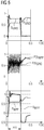
- Fig. 3 shows graphs of simulated "per unit" voltage during and after an asymmetrical grid-side fault arising during control of a HVDC transmission link using the method according to the invention.
- the upper plot in the diagram shows the development in AC voltage level U GRID_A , U GRID_B , U GRID_C for the three phases at the grid side.
- These AC voltages U GRID_A , U GRID_B , U GRID_C are measured at the HVDC-side of the grid transformer 33 in Fig. 1 .
- the centre plot in the diagram shows the development in DC voltage level U GRID , U WPP in the HVDC transmission link measured close to the grid end and the wind power plant end of the HVDC transmission link 2 respectively.
- the difference in magnitude is explained by the inherent cable impedance of the HVDC transmission link 2.
- the lower plot in the diagram shows the development in AC voltage level U WPP_A , U WPP_B , U WPP_C for the three phases at the wind power plant side, i.e. measured at the point of common connection PCC.
- a single line-to-ground fault occurs at about 0.03 s.
- the regulating means 103 provides the unbalanced AC voltages U WPP_A , U WPP_B , U WPP_C .
- the grid-side DC voltage U GRID_ rises sharply and starts to oscillate at double the grid frequency, e.g. at 100 Hz for a 50 Hz grid.
- the increase in grid-side DC voltage U GRID causes an increase in the DC voltage level U WPP at the wind power plant end of the transmission line 2, and this is detected by the detecting means 102 in the control module 100 of the first converter 10, which then assumes control of the power input to the transmission link.
- the regulating means 103 starts to modulate the AC voltages U WPP_A , U WPP_B , U WPP_C to force the wind turbines to react, as explained above with the block diagram of Fig. 2 .
- the centre plot in the diagram shows the development in DC current I GRID , I WPP in the HVDC transmission link measured close to the grid end and the wind power plant end of the HVDC transmission link 2 respectively.
- the lower plot in the diagram shows the development in AC current level I WPP_A , I WPP_B , I WPP_C for the three phases at the wind power plant side, i.e. measured at the point of common connection.
- the wind turbines 4 will only feed balanced current into the collector network 11, so that the three phases of the current have essentially equal magnitudes.
- the first converter could also be act to respond to an asymmetrical fault in the collector network, i.e. on the power plant side of the HVDC transmission link.
Landscapes
- Engineering & Computer Science (AREA)
- Power Engineering (AREA)
- Control Of Eletrric Generators (AREA)
- Inverter Devices (AREA)
Priority Applications (5)
| Application Number | Priority Date | Filing Date | Title |
|---|---|---|---|
| EP11190274.8A EP2597746B1 (en) | 2011-11-23 | 2011-11-23 | Method of controlling the power input to a HVDC transmission link |
| PL11190274T PL2597746T3 (pl) | 2011-11-23 | 2011-11-23 | Sposób sterowania mocą wejściową łącza przesyłowego HVDC |
| US13/676,337 US9362751B2 (en) | 2011-11-23 | 2012-11-14 | Method of controlling the power input to a HVDC transmission link |
| CA2796482A CA2796482C (en) | 2011-11-23 | 2012-11-21 | Method of controlling the power input to a hvdc transmission link |
| CN201210481044.1A CN103138280B (zh) | 2011-11-23 | 2012-11-23 | 控制至高压直流输电线路的电力输入的方法 |
Applications Claiming Priority (1)
| Application Number | Priority Date | Filing Date | Title |
|---|---|---|---|
| EP11190274.8A EP2597746B1 (en) | 2011-11-23 | 2011-11-23 | Method of controlling the power input to a HVDC transmission link |
Publications (2)
| Publication Number | Publication Date |
|---|---|
| EP2597746A1 EP2597746A1 (en) | 2013-05-29 |
| EP2597746B1 true EP2597746B1 (en) | 2020-11-18 |
Family
ID=45033856
Family Applications (1)
| Application Number | Title | Priority Date | Filing Date |
|---|---|---|---|
| EP11190274.8A Active EP2597746B1 (en) | 2011-11-23 | 2011-11-23 | Method of controlling the power input to a HVDC transmission link |
Country Status (5)
| Country | Link |
|---|---|
| US (1) | US9362751B2 (pl) |
| EP (1) | EP2597746B1 (pl) |
| CN (1) | CN103138280B (pl) |
| CA (1) | CA2796482C (pl) |
| PL (1) | PL2597746T3 (pl) |
Families Citing this family (26)
| Publication number | Priority date | Publication date | Assignee | Title |
|---|---|---|---|---|
| EP2528184B1 (en) * | 2011-05-25 | 2014-09-10 | Siemens Aktiengesellschaft | Method and apparatus for controlling a DC-transmission link |
| US9046077B2 (en) * | 2011-12-28 | 2015-06-02 | General Electric Company | Reactive power controller for controlling reactive power in a wind farm |
| CN103336208B (zh) * | 2013-06-27 | 2016-01-20 | 华南理工大学 | 交直流输电系统自适应100Hz保护判据的方法 |
| DE102013215398A1 (de) * | 2013-08-06 | 2015-02-12 | Wobben Properties Gmbh | Verfahren zum Steuern von Windenergieanlagen |
| DE102013018271B4 (de) * | 2013-10-31 | 2016-05-12 | Sew-Eurodrive Gmbh & Co Kg | Antriebssystem |
| WO2015078474A1 (en) | 2013-11-28 | 2015-06-04 | Vestas Wind Systems A/S | A power plant controller for generating a power reference to wind turbine generators |
| EP2940824B1 (en) | 2014-04-29 | 2022-11-23 | General Electric Technology GmbH | Improvements in or relating to voltage source converters |
| US9887557B2 (en) | 2014-09-11 | 2018-02-06 | Cpg Technologies, Llc | Hierarchical power distribution |
| CN107078511B (zh) * | 2014-11-03 | 2019-11-08 | 维斯塔斯风力系统集团公司 | 控制风力发电厂的有功功率生成和风力发电厂的方法 |
| CN107250820B (zh) * | 2015-01-13 | 2019-10-18 | 维斯塔斯风力系统集团公司 | 分体式风力涡轮机转换器系统的直流链路的监测 |
| KR102082140B1 (ko) * | 2015-02-11 | 2020-02-27 | 엘에스산전 주식회사 | Hvdc 시스템에서 전력 값 측정 방법 |
| EP3070807B1 (en) * | 2015-03-19 | 2020-09-09 | General Electric Technology GmbH | Power transmission network |
| EP3070806B1 (en) * | 2015-03-19 | 2020-09-23 | General Electric Technology GmbH | Power transmission network |
| US9887558B2 (en) | 2015-09-09 | 2018-02-06 | Cpg Technologies, Llc | Wired and wireless power distribution coexistence |
| CN108432107B (zh) | 2015-09-21 | 2020-02-28 | Abb瑞士股份有限公司 | 具有斩波电路的多电平变流器 |
| DE102016120149A1 (de) | 2015-10-22 | 2017-04-27 | Ayman S. Abdel-Khalik | Verfahren zum Konvertieren von Hochspannungs-Wechselstrom-Leitungen zu bipolaren Hochspannungs-Gleichstrom-Systemen |
| CN105610193B (zh) * | 2016-02-18 | 2017-12-29 | 华北电力大学 | 一种适用于风电场内部故障时集电网络的等值方法 |
| CN105896584B (zh) * | 2016-04-20 | 2018-01-19 | 南京南瑞继保电气有限公司 | 一种电压源型换流器控制零序电压的方法 |
| EP3780311A1 (en) * | 2018-04-12 | 2021-02-17 | Mitsubishi Electric Corporation | Power conversion system |
| US10826297B2 (en) * | 2018-11-06 | 2020-11-03 | General Electric Company | System and method for wind power generation and transmission in electrical power systems |
| CN112688344B (zh) * | 2019-10-18 | 2026-01-09 | 中国电力科学研究院有限公司 | 一种海上风电基地外送系统风电场频率控制方法和系统 |
| ES3059263T3 (en) * | 2020-03-18 | 2026-03-19 | Ge Vernova Tech Gmbh | Improvements in or relating to bipole power transmission schemes |
| CN114597934B (zh) * | 2020-12-07 | 2025-05-16 | 金风科技股份有限公司 | 风电场控制系统和包括风电场控制系统的风电场 |
| EP4254706A1 (en) | 2022-03-29 | 2023-10-04 | General Electric Technology GmbH | Improvements in or relating to bipole power transmission networks |
| EP4429061A1 (en) * | 2023-03-10 | 2024-09-11 | Abb Schweiz Ag | Grid frequency control in an offshore wind farm |
| EP4592698A1 (en) * | 2024-01-29 | 2025-07-30 | Nordex Energy Spain, S.A.U. | A method for identifying a defect in an electrical component of an energy installation, generator unit, energy installation, computer-implemented method and computer program product |
Family Cites Families (9)
| Publication number | Priority date | Publication date | Assignee | Title |
|---|---|---|---|---|
| US5270640A (en) * | 1992-04-23 | 1993-12-14 | The Penn State Research Foundation | Method for incipient failure detection in electric machines |
| DE60043190D1 (de) * | 2000-06-02 | 2009-12-03 | Abb Ab | Steuerverfahren und System zur Spannungsregelung in einer Umformeranlage |
| JP2003037939A (ja) * | 2001-07-24 | 2003-02-07 | Toshiba Corp | 直流送電システムの制御装置 |
| JP4673428B2 (ja) | 2006-06-30 | 2011-04-20 | アーベーベー・テヒノロギー・アーゲー | Hvdcシステム及びhvdcシステムの電圧源変換器の制御方法 |
| DE102006054870A1 (de) * | 2006-11-20 | 2008-06-12 | Repower Systems Ag | Windenergieanlage mit Gegensystemregelung und Betriebsverfahren |
| EP2140534B1 (en) * | 2007-04-27 | 2018-07-18 | ABB Schweiz AG | Method and system to influence the power generation of an adjustable speed generator |
| US9325173B2 (en) * | 2009-09-15 | 2016-04-26 | The University Of Western Ontario | Utilization of distributed generator inverters as STATCOM |
| US20110163113A1 (en) * | 2010-01-06 | 2011-07-07 | Matthew Eric Grubbs | Dispenser for round and rectangular cans |
| EP2485358B2 (en) * | 2011-02-07 | 2021-12-22 | Siemens Gamesa Renewable Energy A/S | System and method for mitigating an electric unbalance of a three-phase current at a Point of Common Coupling between a wind farm and a power grid |
-
2011
- 2011-11-23 PL PL11190274T patent/PL2597746T3/pl unknown
- 2011-11-23 EP EP11190274.8A patent/EP2597746B1/en active Active
-
2012
- 2012-11-14 US US13/676,337 patent/US9362751B2/en active Active
- 2012-11-21 CA CA2796482A patent/CA2796482C/en active Active
- 2012-11-23 CN CN201210481044.1A patent/CN103138280B/zh not_active Expired - Fee Related
Non-Patent Citations (1)
| Title |
|---|
| None * |
Also Published As
| Publication number | Publication date |
|---|---|
| US20130128630A1 (en) | 2013-05-23 |
| US9362751B2 (en) | 2016-06-07 |
| CA2796482C (en) | 2019-12-31 |
| PL2597746T3 (pl) | 2021-10-18 |
| CA2796482A1 (en) | 2013-05-23 |
| CN103138280A (zh) | 2013-06-05 |
| CN103138280B (zh) | 2017-01-18 |
| EP2597746A1 (en) | 2013-05-29 |
Similar Documents
| Publication | Publication Date | Title |
|---|---|---|
| EP2597746B1 (en) | Method of controlling the power input to a HVDC transmission link | |
| US9671442B2 (en) | System and method for detecting a grid event | |
| EP2528184B1 (en) | Method and apparatus for controlling a DC-transmission link | |
| CA2825504C (en) | Method and systems for operating a wind turbine using dynamic braking in response to a grid event | |
| US8880228B2 (en) | System and method for mitigating an electric unbalance of a three-phase current at a point of common coupling between a wind farm and a power grid | |
| KR101850663B1 (ko) | 전기 공급 그리드 내로의 전기 에너지의 공급 방법 및 그 장치 | |
| JP6163494B2 (ja) | 電力変換器、および電力変換器を制御する方法 | |
| EP2688172B1 (en) | Method and apparatus for adaptively controlling wind park turbines | |
| US9528496B2 (en) | Fast run-back control including plant losses | |
| EP2922170B1 (en) | Control device for voltage source converter and operating method thereof | |
| CN104620460A (zh) | 低电压或高电压事件期间的发电设备控制 | |
| EP2947743A2 (en) | Converter and operating method thereof | |
| CN105633997A (zh) | 风力发电机组电压穿越控制方法和装置 | |
| CN109314395A (zh) | 与多个可再生能源发电厂的互连有关的改进 | |
| EP2863512B1 (en) | Power system, operation method thereof and control device for power system | |
| CN105243230B (zh) | 一种计及卸荷电路的直驱风电场的等值建模方法 | |
| WO2012081412A1 (ja) | 電力変換装置、電力変換装置の制御装置及び電力変換装置の制御方法 | |
| CN105633999A (zh) | 电网电压不平衡骤升下高电压穿越的控制方法和装置 | |
| EP2867970B1 (en) | Method and controller for continuously operating a plurality of electric energy generating machines during a high voltage condition | |
| CN110768297A (zh) | 一种具备高电压穿越功能的风电机组孤岛切出方法及装置 | |
| US20150263508A1 (en) | System and method for detecting islanding of electrical machines and protecting same | |
| Otremba et al. | Design of Stand-Alone O&G Water Injection System Fed by Wind Generation with Battery Support | |
| Drid et al. | Variable speed doubly fed induction generators power control with wind turbine maximum power point tracking |
Legal Events
| Date | Code | Title | Description |
|---|---|---|---|
| PUAI | Public reference made under article 153(3) epc to a published international application that has entered the european phase |
Free format text: ORIGINAL CODE: 0009012 |
|
| AK | Designated contracting states |
Kind code of ref document: A1 Designated state(s): AL AT BE BG CH CY CZ DE DK EE ES FI FR GB GR HR HU IE IS IT LI LT LU LV MC MK MT NL NO PL PT RO RS SE SI SK SM TR |
|
| AX | Request for extension of the european patent |
Extension state: BA ME |
|
| 17P | Request for examination filed |
Effective date: 20130620 |
|
| RBV | Designated contracting states (corrected) |
Designated state(s): AL AT BE BG CH CY CZ DE DK EE ES FI FR GB GR HR HU IE IS IT LI LT LU LV MC MK MT NL NO PL PT RO RS SE SI SK SM TR |
|
| RAP1 | Party data changed (applicant data changed or rights of an application transferred) |
Owner name: SIEMENS AKTIENGESELLSCHAFT |
|
| STAA | Information on the status of an ep patent application or granted ep patent |
Free format text: STATUS: EXAMINATION IS IN PROGRESS |
|
| 17Q | First examination report despatched |
Effective date: 20190123 |
|
| GRAP | Despatch of communication of intention to grant a patent |
Free format text: ORIGINAL CODE: EPIDOSNIGR1 |
|
| STAA | Information on the status of an ep patent application or granted ep patent |
Free format text: STATUS: GRANT OF PATENT IS INTENDED |
|
| INTG | Intention to grant announced |
Effective date: 20200708 |
|
| GRAS | Grant fee paid |
Free format text: ORIGINAL CODE: EPIDOSNIGR3 |
|
| GRAA | (expected) grant |
Free format text: ORIGINAL CODE: 0009210 |
|
| STAA | Information on the status of an ep patent application or granted ep patent |
Free format text: STATUS: THE PATENT HAS BEEN GRANTED |
|
| AK | Designated contracting states |
Kind code of ref document: B1 Designated state(s): AL AT BE BG CH CY CZ DE DK EE ES FI FR GB GR HR HU IE IS IT LI LT LU LV MC MK MT NL NO PL PT RO RS SE SI SK SM TR |
|
| REG | Reference to a national code |
Ref country code: GB Ref legal event code: FG4D |
|
| REG | Reference to a national code |
Ref country code: CH Ref legal event code: EP |
|
| REG | Reference to a national code |
Ref country code: IE Ref legal event code: FG4D |
|
| REG | Reference to a national code |
Ref country code: DE Ref legal event code: R096 Ref document number: 602011069326 Country of ref document: DE |
|
| REG | Reference to a national code |
Ref country code: AT Ref legal event code: REF Ref document number: 1336811 Country of ref document: AT Kind code of ref document: T Effective date: 20201215 Ref country code: DE Ref legal event code: R081 Ref document number: 602011069326 Country of ref document: DE Owner name: SIEMENS ENERGY GLOBAL GMBH & CO. KG, DE Free format text: FORMER OWNER: SIEMENS AKTIENGESELLSCHAFT, 80333 MUENCHEN, DE |
|
| RAP2 | Party data changed (patent owner data changed or rights of a patent transferred) |
Owner name: SIEMENS ENERGY GLOBAL GMBH & CO. KG |
|
| REG | Reference to a national code |
Ref country code: NL Ref legal event code: PD Owner name: SIEMENS ENERGY GLOBAL GMBH & CO. KG; DE Free format text: DETAILS ASSIGNMENT: CHANGE OF OWNER(S), ASSIGNMENT; FORMER OWNER NAME: SIEMENS AKTIENGESELLSCHAFT Effective date: 20210210 Ref country code: NL Ref legal event code: FP |
|
| REG | Reference to a national code |
Ref country code: AT Ref legal event code: MK05 Ref document number: 1336811 Country of ref document: AT Kind code of ref document: T Effective date: 20201118 |
|
| PG25 | Lapsed in a contracting state [announced via postgrant information from national office to epo] |
Ref country code: RS Free format text: LAPSE BECAUSE OF FAILURE TO SUBMIT A TRANSLATION OF THE DESCRIPTION OR TO PAY THE FEE WITHIN THE PRESCRIBED TIME-LIMIT Effective date: 20201118 Ref country code: FI Free format text: LAPSE BECAUSE OF FAILURE TO SUBMIT A TRANSLATION OF THE DESCRIPTION OR TO PAY THE FEE WITHIN THE PRESCRIBED TIME-LIMIT Effective date: 20201118 Ref country code: PT Free format text: LAPSE BECAUSE OF FAILURE TO SUBMIT A TRANSLATION OF THE DESCRIPTION OR TO PAY THE FEE WITHIN THE PRESCRIBED TIME-LIMIT Effective date: 20210318 Ref country code: NO Free format text: LAPSE BECAUSE OF FAILURE TO SUBMIT A TRANSLATION OF THE DESCRIPTION OR TO PAY THE FEE WITHIN THE PRESCRIBED TIME-LIMIT Effective date: 20210218 Ref country code: GR Free format text: LAPSE BECAUSE OF FAILURE TO SUBMIT A TRANSLATION OF THE DESCRIPTION OR TO PAY THE FEE WITHIN THE PRESCRIBED TIME-LIMIT Effective date: 20210219 |
|
| PG25 | Lapsed in a contracting state [announced via postgrant information from national office to epo] |
Ref country code: SE Free format text: LAPSE BECAUSE OF FAILURE TO SUBMIT A TRANSLATION OF THE DESCRIPTION OR TO PAY THE FEE WITHIN THE PRESCRIBED TIME-LIMIT Effective date: 20201118 Ref country code: LV Free format text: LAPSE BECAUSE OF FAILURE TO SUBMIT A TRANSLATION OF THE DESCRIPTION OR TO PAY THE FEE WITHIN THE PRESCRIBED TIME-LIMIT Effective date: 20201118 Ref country code: IS Free format text: LAPSE BECAUSE OF FAILURE TO SUBMIT A TRANSLATION OF THE DESCRIPTION OR TO PAY THE FEE WITHIN THE PRESCRIBED TIME-LIMIT Effective date: 20210318 Ref country code: AT Free format text: LAPSE BECAUSE OF FAILURE TO SUBMIT A TRANSLATION OF THE DESCRIPTION OR TO PAY THE FEE WITHIN THE PRESCRIBED TIME-LIMIT Effective date: 20201118 Ref country code: BG Free format text: LAPSE BECAUSE OF FAILURE TO SUBMIT A TRANSLATION OF THE DESCRIPTION OR TO PAY THE FEE WITHIN THE PRESCRIBED TIME-LIMIT Effective date: 20210218 |
|
| REG | Reference to a national code |
Ref country code: LT Ref legal event code: MG9D |
|
| PG25 | Lapsed in a contracting state [announced via postgrant information from national office to epo] |
Ref country code: HR Free format text: LAPSE BECAUSE OF FAILURE TO SUBMIT A TRANSLATION OF THE DESCRIPTION OR TO PAY THE FEE WITHIN THE PRESCRIBED TIME-LIMIT Effective date: 20201118 |
|
| REG | Reference to a national code |
Ref country code: CH Ref legal event code: PL |
|
| PG25 | Lapsed in a contracting state [announced via postgrant information from national office to epo] |
Ref country code: RO Free format text: LAPSE BECAUSE OF FAILURE TO SUBMIT A TRANSLATION OF THE DESCRIPTION OR TO PAY THE FEE WITHIN THE PRESCRIBED TIME-LIMIT Effective date: 20201118 Ref country code: SK Free format text: LAPSE BECAUSE OF FAILURE TO SUBMIT A TRANSLATION OF THE DESCRIPTION OR TO PAY THE FEE WITHIN THE PRESCRIBED TIME-LIMIT Effective date: 20201118 Ref country code: LT Free format text: LAPSE BECAUSE OF FAILURE TO SUBMIT A TRANSLATION OF THE DESCRIPTION OR TO PAY THE FEE WITHIN THE PRESCRIBED TIME-LIMIT Effective date: 20201118 Ref country code: LU Free format text: LAPSE BECAUSE OF NON-PAYMENT OF DUE FEES Effective date: 20201123 Ref country code: SM Free format text: LAPSE BECAUSE OF FAILURE TO SUBMIT A TRANSLATION OF THE DESCRIPTION OR TO PAY THE FEE WITHIN THE PRESCRIBED TIME-LIMIT Effective date: 20201118 Ref country code: EE Free format text: LAPSE BECAUSE OF FAILURE TO SUBMIT A TRANSLATION OF THE DESCRIPTION OR TO PAY THE FEE WITHIN THE PRESCRIBED TIME-LIMIT Effective date: 20201118 Ref country code: CZ Free format text: LAPSE BECAUSE OF FAILURE TO SUBMIT A TRANSLATION OF THE DESCRIPTION OR TO PAY THE FEE WITHIN THE PRESCRIBED TIME-LIMIT Effective date: 20201118 |
|
| REG | Reference to a national code |
Ref country code: BE Ref legal event code: MM Effective date: 20201130 |
|
| REG | Reference to a national code |
Ref country code: DE Ref legal event code: R097 Ref document number: 602011069326 Country of ref document: DE |
|
| PG25 | Lapsed in a contracting state [announced via postgrant information from national office to epo] |
Ref country code: DK Free format text: LAPSE BECAUSE OF FAILURE TO SUBMIT A TRANSLATION OF THE DESCRIPTION OR TO PAY THE FEE WITHIN THE PRESCRIBED TIME-LIMIT Effective date: 20201118 Ref country code: CH Free format text: LAPSE BECAUSE OF NON-PAYMENT OF DUE FEES Effective date: 20201130 Ref country code: MC Free format text: LAPSE BECAUSE OF FAILURE TO SUBMIT A TRANSLATION OF THE DESCRIPTION OR TO PAY THE FEE WITHIN THE PRESCRIBED TIME-LIMIT Effective date: 20201118 Ref country code: LI Free format text: LAPSE BECAUSE OF NON-PAYMENT OF DUE FEES Effective date: 20201130 |
|
| PLBE | No opposition filed within time limit |
Free format text: ORIGINAL CODE: 0009261 |
|
| STAA | Information on the status of an ep patent application or granted ep patent |
Free format text: STATUS: NO OPPOSITION FILED WITHIN TIME LIMIT |
|
| 26N | No opposition filed |
Effective date: 20210819 |
|
| PG25 | Lapsed in a contracting state [announced via postgrant information from national office to epo] |
Ref country code: AL Free format text: LAPSE BECAUSE OF FAILURE TO SUBMIT A TRANSLATION OF THE DESCRIPTION OR TO PAY THE FEE WITHIN THE PRESCRIBED TIME-LIMIT Effective date: 20201118 Ref country code: IT Free format text: LAPSE BECAUSE OF FAILURE TO SUBMIT A TRANSLATION OF THE DESCRIPTION OR TO PAY THE FEE WITHIN THE PRESCRIBED TIME-LIMIT Effective date: 20201118 Ref country code: IE Free format text: LAPSE BECAUSE OF NON-PAYMENT OF DUE FEES Effective date: 20201123 |
|
| PG25 | Lapsed in a contracting state [announced via postgrant information from national office to epo] |
Ref country code: ES Free format text: LAPSE BECAUSE OF FAILURE TO SUBMIT A TRANSLATION OF THE DESCRIPTION OR TO PAY THE FEE WITHIN THE PRESCRIBED TIME-LIMIT Effective date: 20201118 Ref country code: SI Free format text: LAPSE BECAUSE OF FAILURE TO SUBMIT A TRANSLATION OF THE DESCRIPTION OR TO PAY THE FEE WITHIN THE PRESCRIBED TIME-LIMIT Effective date: 20201118 |
|
| REG | Reference to a national code |
Ref country code: GB Ref legal event code: 732E Free format text: REGISTERED BETWEEN 20211202 AND 20211209 |
|
| PG25 | Lapsed in a contracting state [announced via postgrant information from national office to epo] |
Ref country code: IS Free format text: LAPSE BECAUSE OF FAILURE TO SUBMIT A TRANSLATION OF THE DESCRIPTION OR TO PAY THE FEE WITHIN THE PRESCRIBED TIME-LIMIT Effective date: 20210318 Ref country code: TR Free format text: LAPSE BECAUSE OF FAILURE TO SUBMIT A TRANSLATION OF THE DESCRIPTION OR TO PAY THE FEE WITHIN THE PRESCRIBED TIME-LIMIT Effective date: 20201118 Ref country code: MT Free format text: LAPSE BECAUSE OF FAILURE TO SUBMIT A TRANSLATION OF THE DESCRIPTION OR TO PAY THE FEE WITHIN THE PRESCRIBED TIME-LIMIT Effective date: 20201118 Ref country code: CY Free format text: LAPSE BECAUSE OF FAILURE TO SUBMIT A TRANSLATION OF THE DESCRIPTION OR TO PAY THE FEE WITHIN THE PRESCRIBED TIME-LIMIT Effective date: 20201118 |
|
| PG25 | Lapsed in a contracting state [announced via postgrant information from national office to epo] |
Ref country code: MK Free format text: LAPSE BECAUSE OF FAILURE TO SUBMIT A TRANSLATION OF THE DESCRIPTION OR TO PAY THE FEE WITHIN THE PRESCRIBED TIME-LIMIT Effective date: 20201118 |
|
| PG25 | Lapsed in a contracting state [announced via postgrant information from national office to epo] |
Ref country code: BE Free format text: LAPSE BECAUSE OF NON-PAYMENT OF DUE FEES Effective date: 20201130 |
|
| PGFP | Annual fee paid to national office [announced via postgrant information from national office to epo] |
Ref country code: NL Payment date: 20251124 Year of fee payment: 15 |
|
| PGFP | Annual fee paid to national office [announced via postgrant information from national office to epo] |
Ref country code: DE Payment date: 20251126 Year of fee payment: 15 |
|
| PGFP | Annual fee paid to national office [announced via postgrant information from national office to epo] |
Ref country code: GB Payment date: 20251125 Year of fee payment: 15 |
|
| PGFP | Annual fee paid to national office [announced via postgrant information from national office to epo] |
Ref country code: FR Payment date: 20251124 Year of fee payment: 15 |
|
| PGFP | Annual fee paid to national office [announced via postgrant information from national office to epo] |
Ref country code: PL Payment date: 20251028 Year of fee payment: 15 |