EP2597310A2 - Verfahren zum Betreiben einer drehzahlvariablen Verstellpumpe - Google Patents
Verfahren zum Betreiben einer drehzahlvariablen Verstellpumpe Download PDFInfo
- Publication number
- EP2597310A2 EP2597310A2 EP12007291.3A EP12007291A EP2597310A2 EP 2597310 A2 EP2597310 A2 EP 2597310A2 EP 12007291 A EP12007291 A EP 12007291A EP 2597310 A2 EP2597310 A2 EP 2597310A2
- Authority
- EP
- European Patent Office
- Prior art keywords
- speed
- value
- actual
- variable
- delivery pressure
- Prior art date
- Legal status (The legal status is an assumption and is not a legal conclusion. Google has not performed a legal analysis and makes no representation as to the accuracy of the status listed.)
- Granted
Links
- 238000000034 method Methods 0.000 title claims abstract description 19
- 238000006073 displacement reaction Methods 0.000 claims description 14
- 239000000654 additive Substances 0.000 claims 1
- 230000000996 additive effect Effects 0.000 claims 1
- 230000001105 regulatory effect Effects 0.000 claims 1
- 230000006870 function Effects 0.000 description 7
- 238000012544 monitoring process Methods 0.000 description 3
- 238000004364 calculation method Methods 0.000 description 2
- 239000000969 carrier Substances 0.000 description 1
- 238000004590 computer program Methods 0.000 description 1
- 230000001419 dependent effect Effects 0.000 description 1
- 238000001746 injection moulding Methods 0.000 description 1
- 238000002955 isolation Methods 0.000 description 1
- 230000015654 memory Effects 0.000 description 1
- 230000001360 synchronised effect Effects 0.000 description 1
- 230000002123 temporal effect Effects 0.000 description 1
- 230000001960 triggered effect Effects 0.000 description 1
Images

Classifications
-
- F—MECHANICAL ENGINEERING; LIGHTING; HEATING; WEAPONS; BLASTING
- F04—POSITIVE - DISPLACEMENT MACHINES FOR LIQUIDS; PUMPS FOR LIQUIDS OR ELASTIC FLUIDS
- F04B—POSITIVE-DISPLACEMENT MACHINES FOR LIQUIDS; PUMPS
- F04B49/00—Control, e.g. of pump delivery, or pump pressure of, or safety measures for, machines, pumps, or pumping installations, not otherwise provided for, or of interest apart from, groups F04B1/00 - F04B47/00
- F04B49/002—Hydraulic systems to change the pump delivery
-
- F—MECHANICAL ENGINEERING; LIGHTING; HEATING; WEAPONS; BLASTING
- F04—POSITIVE - DISPLACEMENT MACHINES FOR LIQUIDS; PUMPS FOR LIQUIDS OR ELASTIC FLUIDS
- F04B—POSITIVE-DISPLACEMENT MACHINES FOR LIQUIDS; PUMPS
- F04B49/00—Control, e.g. of pump delivery, or pump pressure of, or safety measures for, machines, pumps, or pumping installations, not otherwise provided for, or of interest apart from, groups F04B1/00 - F04B47/00
- F04B49/06—Control using electricity
-
- F—MECHANICAL ENGINEERING; LIGHTING; HEATING; WEAPONS; BLASTING
- F04—POSITIVE - DISPLACEMENT MACHINES FOR LIQUIDS; PUMPS FOR LIQUIDS OR ELASTIC FLUIDS
- F04B—POSITIVE-DISPLACEMENT MACHINES FOR LIQUIDS; PUMPS
- F04B49/00—Control, e.g. of pump delivery, or pump pressure of, or safety measures for, machines, pumps, or pumping installations, not otherwise provided for, or of interest apart from, groups F04B1/00 - F04B47/00
- F04B49/12—Control, e.g. of pump delivery, or pump pressure of, or safety measures for, machines, pumps, or pumping installations, not otherwise provided for, or of interest apart from, groups F04B1/00 - F04B47/00 by varying the length of stroke of the working members
-
- F—MECHANICAL ENGINEERING; LIGHTING; HEATING; WEAPONS; BLASTING
- F04—POSITIVE - DISPLACEMENT MACHINES FOR LIQUIDS; PUMPS FOR LIQUIDS OR ELASTIC FLUIDS
- F04B—POSITIVE-DISPLACEMENT MACHINES FOR LIQUIDS; PUMPS
- F04B1/00—Multi-cylinder machines or pumps characterised by number or arrangement of cylinders
- F04B1/04—Multi-cylinder machines or pumps characterised by number or arrangement of cylinders having cylinders in star- or fan-arrangement
- F04B1/06—Control
-
- F—MECHANICAL ENGINEERING; LIGHTING; HEATING; WEAPONS; BLASTING
- F04—POSITIVE - DISPLACEMENT MACHINES FOR LIQUIDS; PUMPS FOR LIQUIDS OR ELASTIC FLUIDS
- F04B—POSITIVE-DISPLACEMENT MACHINES FOR LIQUIDS; PUMPS
- F04B2203/00—Motor parameters
- F04B2203/02—Motor parameters of rotating electric motors
- F04B2203/0209—Rotational speed
-
- F—MECHANICAL ENGINEERING; LIGHTING; HEATING; WEAPONS; BLASTING
- F04—POSITIVE - DISPLACEMENT MACHINES FOR LIQUIDS; PUMPS FOR LIQUIDS OR ELASTIC FLUIDS
- F04B—POSITIVE-DISPLACEMENT MACHINES FOR LIQUIDS; PUMPS
- F04B49/00—Control, e.g. of pump delivery, or pump pressure of, or safety measures for, machines, pumps, or pumping installations, not otherwise provided for, or of interest apart from, groups F04B1/00 - F04B47/00
- F04B49/08—Regulating by delivery pressure
-
- F—MECHANICAL ENGINEERING; LIGHTING; HEATING; WEAPONS; BLASTING
- F04—POSITIVE - DISPLACEMENT MACHINES FOR LIQUIDS; PUMPS FOR LIQUIDS OR ELASTIC FLUIDS
- F04B—POSITIVE-DISPLACEMENT MACHINES FOR LIQUIDS; PUMPS
- F04B49/00—Control, e.g. of pump delivery, or pump pressure of, or safety measures for, machines, pumps, or pumping installations, not otherwise provided for, or of interest apart from, groups F04B1/00 - F04B47/00
- F04B49/20—Control, e.g. of pump delivery, or pump pressure of, or safety measures for, machines, pumps, or pumping installations, not otherwise provided for, or of interest apart from, groups F04B1/00 - F04B47/00 by changing the driving speed
Definitions
- the present invention relates to a method for operating a variable speed variable displacement pump according to the preamble of claim 1, a computing unit for its implementation and a variable speed variable displacement pump with such a computing unit.
- the pumps on which the invention is based consist of a conveyor with variable displacement (per stroke or revolution), which is driven by a drive with variable speed.
- the volumetric flow rate and / or the delivery pressure i.e., pressure difference between inlet and outlet
- Such pumps have two degrees of freedom in the control.
- the object is to improve the operation of such pumps in non-cyclical machines.
- the invention provides a way to significantly increase the dynamics of a speed change in variable-speed variable displacement pumps and thus counteract a delivery pressure drop with large changes in quantity. This allows the restriction-free use of such pumps even in non-cyclical machines.
- the invention uses to increase the target speed in the context of a feedforward control upon entry of at least one predetermined triggering condition. This is done, for example, by triggering a ramp function and / or by applying the setpoint speed with a precontrol value.
- the setpoint speed is usually determined as a function of the actual delivery volume.
- the speed is subject to a limited dynamics, so that they can not follow changes arbitrarily fast. It comes to the pressure drop.
- an optionally energy-optimal operating point in favor of better dynamics is now left by the precontrol, the pressure drops are at least reduced.
- the additional pilot signal for speed also leads to improved dynamics of the pump.
- the target speed is thereby increased so that there is a maximum possible speed gradient.
- driving the setpoint speed is usually performed via a ramp function, so that the drive is applied to a continuous increase in speed.
- the gradient of the ramp is essentially determined by the difference between the output speed and the increased set speed, wherein a maximum gradient (usually constructive condition) must be taken into account.
- a specification of the target speed so that the maximum possible speed gradient results in the fastest possible speed increase to keep pressure drops as short as possible.
- the invention reduces the time delay between the switching operation in the pump-driven machine (which leads to a change in quantity) and the start of the speed ramp.
- the speed control is intervened and the setpoint speed is increased, so that a higher setpoint speed is specified for the drive than would result from the control alone.
- a threshold value monitoring of the difference between nominal delivery pressure p soll and actual delivery pressure p is suitable as the triggering condition for the speed increase. If the difference exceeds a predefinable threshold value, this indicates an incipient pressure drop, which is to be counteracted.
- a trigger condition for the speed increase is also a threshold value monitoring of a temporal gradient of the (actual or target) delivery volume. If, for example, the (actual or target) delivery volume rises sharply in a short time, this can, as described, likewise lead to a pressure drop, which is to be counteracted.
- triggering conditions are in a preferred embodiment essentially only in the arithmetic unit ("controller") known or derived variables, in particular target delivery pressure p soll , actual delivery pressure p is , target volume flow Q soll , actual volume flow Q is , target delivery volume V soll , actual delivery volume V is , times, manipulated variables of the conveyor, such as, for example, the swivel angle for axial piston pumps, the setpoint speed and the actual speed.
- controller known or derived variables, in particular target delivery pressure p soll , actual delivery pressure p is , target volume flow Q soll , actual volume flow Q is , target delivery volume V soll , actual delivery volume V is , times, manipulated variables of the conveyor, such as, for example, the swivel angle for axial piston pumps, the setpoint speed and the actual speed.
- the invention can therefore be implemented particularly advantageously also in existing systems, in particular by means of a software update.
- the feedforward control may, for example, include a proportional element with a matching proportional gain K P into which, for example, the difference between the desired delivery pressure p soll and the actual delivery pressure p is received.
- a suitable proportional gain K P can be determined as a function of the system.
- the invention develops particular advantages in the field of injection molding machines, presses, woodworking machines, test benches, etc., since here a pressure drop is particularly disadvantageous.
- the use or the use of the invention in these areas is therefore particularly useful.
- An arithmetic unit according to the invention e.g. a control unit of a variable-speed variable, is, in particular programmatically, adapted to perform a method according to the invention.
- the arithmetic unit is for example an integrated electronics (for example ASIC) on the pump or in the converter or an external controller.
- Suitable data carriers for providing the computer program are, in particular, floppy disks, hard disks, flash memories, EEPROMs, CD-ROMs, DVDs and the like. It is also possible to download a program via computer networks (Internet, intranet, etc.).
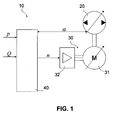
- variable displacement pump 10 has an adjustable conveyor 20 (which can feed in two directions in the present example), a variable speed drive 30, and a computer 40 for operating the pump.
- the conveyor 20 is formed as an axial piston pump with an adjustable swivel angle ⁇ for a swash plate or inclined axis, in which the swivel angle ⁇ for setting a delivery volume V per stroke or rotation can be specified.
- a control signal from the arithmetic unit 40 is given to the axial piston pump 20 and an actual pivot angle is returned.
- the control signal may, for example, be a desired value for a so-called pilot valve on the pump.
- the drive is designed here as a so-called standard motor, which has an asynchronous motor 31 and a frequency converter 32.
- synchronous servomotors can also be used.
- the rotational speed n of the asynchronous motor 31 is variable.
- a desired rotational speed is predetermined by the arithmetic unit 40 to the drive 30.
- the actual speed can be determined by an angle encoder or by calculation, as for example. In the DE 10 2009 055 978 A1 is disclosed.
- the arithmetic unit 40 which is supplied to a target delivery pressure p and a target volume flow Q is used.
- the arithmetic unit determines the two manipulated variables available, rotational speed n and a control signal for the swivel angle ⁇ of the control pump. A preferred way of determination will be described below with reference to FIG. 2 1, which schematically illustrates a control according to a preferred embodiment of the invention, which may be implemented in the arithmetic unit 40.
- the lower part of the control scheme shows a common pump control.
- the pump control generates setpoints for the speed n soll and a control signal ⁇ to (it is not in this case usually by an angle set point, but rather a control signal for a pilot valve) based on the desired operating point p should, Q should.
- Logic member 201 is provided, which is based on the desired operating point p soll , Q soll determines the setpoints. In particular, computing methods are known for this, which enable energy-saving operation.
- the target rotational speed n set for example, is then. Forwarded to the drive 30, the drive controller 32, the speed of the electric motor 31 to the target speed n soll adjusts.
- a pivot angle is set at the conveyor.
- Such a regulation is, for example, from the DE 10 2009 018 071 A1 which is why it is not necessary to go deeper into this at this point.
- this basic pump control is extended by a functionality for adjusting the target speed in order to increase the dynamics of the pump and to prevent pressure drops.
- This pilot control is at the top of the FIG. 2 shown. If a certain triggering condition occurs, the setpoint speed is increased.
- an up ramp function 202 is triggered within the pump controller 201, so that the target speed is continuously increased.
- the ramp-up function 202 continuously increases the desired speed until a predeterminable threshold is reached and / or the ramp-up function is terminated.
- the speed increase may also include applying the speed setpoint n soll to a pre-control value n +.
- the logic element 203 can also contain, for example, a proportional element with appropriate proportional gain K P , into which, for example, a difference between a nominal value and an actual value is received (for example, target delivery pressure p soll , actual delivery pressure p ist , target value). is volume flow Q target, actual volume flow is Q, the target swivel angle ⁇ should actual pivot angle ⁇ ).
- the trigger condition is monitored as to whether, for example, the difference between the setpoint pressure p soll and the actual pressure p ist exceeds a predetermined threshold value.
- the threshold can be selected in absolute or percentage terms.
- a logic element 203 is provided, which at the same time also determines and outputs the precontrol value n + .
- the determination can be carried out, for example, on the basis of a characteristic map which can depend on at least one of the following variables: target delivery pressure p soll , actual delivery pressure p ist , target volume flow Q soll , actual volume flow Q ist , target pivot angle ⁇ soll , Actual swivel angle ⁇ is setpoint speed n soll and actual speed.
Landscapes
- Engineering & Computer Science (AREA)
- Mechanical Engineering (AREA)
- General Engineering & Computer Science (AREA)
- Control Of Positive-Displacement Pumps (AREA)
- Details And Applications Of Rotary Liquid Pumps (AREA)
- Control Of Non-Positive-Displacement Pumps (AREA)
Abstract
Description
- Die vorliegende Erfindung betrifft ein Verfahren zum Betreiben einer drehzahlvariablen Verstellpumpe nach dem Oberbegriff des Anspruchs 1, eine Recheneinheit zu dessen Durchführung sowie eine drehzahlvariable Verstellpumpe mit einer solchen Recheneinheit.
- Der Erfindung zugrunde liegende Pumpen bestehen aus einem Förderwerk mit variablem Fördervolumen (pro Hub bzw. Umdrehung), welches von einem Antrieb mit variabler Drehzahl angetrieben wird. Beim Betrieb solcher Pumpen werden üblicherweise der Volumenstrom und/oder der Förderdruck (d.h. Druckdifferenz zwischen Zulauf und Ablauf) durch entsprechende Anpassung des Fördervolumens des Förderwerks und der Drehzahl geregelt, d.h. solche Pumpen besitzen zwei Freiheitsgrade bei der Regelung.
- In der
DE 10 2009 018 071 A1 wird in diesem Zusammenhang ein Verfahren zur Regelung einer Druckmittelzufuhr offenbart, um mit einer solchen Pumpe einen hydraulischen Aktor einer zyklisch arbeitenden Maschine zu betreiben. Hierbei werden eine optimale Antriebsdrehzahl sowie ein Fördervolumen für einen geforderten Druck und einen geforderten Volumenstrom bestimmt. Bei dem Einsatz einer solchen Pumpe in einer nicht zyklisch arbeitenden Maschine ergibt sich der Nachteil, dass bei größeren Mengenänderungen das Aufregelverhalten durch die Dynamik der Drehzahländerung begrenzt wird. Dies kann u.U. zu einem Einbruch des Förderdrucks führen. - Es stellt sich die Aufgabe, den Betrieb solcher Pumpen in nicht zyklisch arbeitenden Maschinen zu verbessern.
- Erfindungsgemäß werden ein Verfahren zum Betreiben einer drehzahlvariablen Verstellpumpe, eine Recheneinheit zu dessen Durchführung sowie eine drehzahlvariable Verstellpumpe aufweisend eine solche Recheneinheit mit den Merkmalen der unabhängigen Patentansprüche vorgeschlagen. Vorteilhafte Ausgestaltungen sind Gegenstand der Unteransprüche sowie der nachfolgenden Beschreibung.
- Die Erfindung schafft eine Möglichkeit, die Dynamik einer Drehzahländerung bei drehzahlvariablen Verstellpumpen deutlich zu erhöhen und so einem Förderdruckabfall bei großen Mengenänderungen entgegenzuwirken. Dies ermöglicht den einschränkungsfreien Einsatz solcher Pumpen auch in nicht zyklisch arbeitenden Maschinen. Die Erfindung bedient sich dazu der Anhebung der Soll-Drehzahl im Rahmen einer Vorsteuerung bei Eintritt wenigstens einer vorbestimmten Auslösebedingung. Dies erfolgt beispielsweise durch Auslösen einer Rampenfunktion und/oder durch Beaufschlagen der Soll-Drehzahl mit einem Vorsteuerwert.
- Im Stand der Technik wird beim Betrieb der Pumpe zur Druckregelung die Soll-Drehzahl üblicherweise in Abhängigkeit vom Ist-Fördervolumen bestimmt. Die Drehzahl unterliegt jedoch einer begrenzten Dynamik, so dass sie Änderungen nicht beliebig schnell folgen kann. Es kommt zum Druckeinbruch. Im Rahmen der Erfindung wird nun durch die Vorsteuerung ein ggf. energieoptimaler Arbeitspunkt zugunsten einer besseren Dynamik verlassen, die Druckeinbrüche werden zumindest reduziert. Das zusätzliche Vorsteuersignal für Drehzahl führt ebenfalls zu einer verbesserten Dynamik der Pumpe.
- Vorzugsweise wird die Soll-Drehzahl dabei so erhöht, dass sich ein maximal möglicher Drehzahlgradient ergibt. Bei der Ansteuerung wird die Soll-Drehzahl üblicherweise über eine Rampenfunktion geführt, so dass am Antrieb eine kontinuierliche Drehzahlerhöhung anliegt. Der Gradient der Rampe bestimmt sich im Wesentlichen aus dem Unterschied zwischen der Ausgangsdrehzahl und der erhöhten Soll-Drehzahl, wobei ein Maximalgradient (meist konstruktiv bedingt) berücksichtigt werden muss. Eine Vorgabe der Soll-Drehzahl so, dass sich der maximal mögliche Drehzahlgradient ergibt, führt zu einer schnellst möglichen Drehzahlanhebung, um Druckeinbrüche möglichst kurz zu halten. Zusätzlich wird durch die Erfindung der Zeitverzug zwischen Schaltvorgang in der von der Pumpe angetriebenen Maschine (was zu einer Mengenänderung führt) und Start der Drehzahlrampe verringert.
- Liegt wenigstens eine Auslösebedingung vor, wird in die Drehzahlregelung eingegriffen und die Soll-Drehzahl erhöht, so dass eine höhere Soll-Drehzahl an den Antrieb vorgegeben wird, als sich aus der Regelung alleine ergäbe.
- Als Auslösebedingung für die Drehzahlanhebung eignet sich insbesondere eine Schwellwertüberwachung des Unterschieds zwischen Soll-Förderdruck psoll und Ist-Förderdruck pist. Übersteigt der Unterschied einen vorgebbaren Schwellwert, zeigt dies einen beginnenden Druckeinbruch an, dem entgegengewirkt werden soll.
- Als Auslösebedingung für die Drehzahlanhebung eignet sich ebenso eine Schwellwertüberwachung eines zeitlichen Gradienten des (Ist- oder Soll-)Fördervolumens. Steigt bspw. das (Ist- oder Soll-)Fördervolumen in kurzer Zeit stark an, kann dies, wie beschrieben, ebenfalls zu einem Druckeinbruch führen, dem entgegengewirkt werden soll.
- In die Auslösebedingungen gehen in bevorzugter Ausgestaltung im Wesentlichen nur in der Recheneinheit ("Regler") ohnehin bekannte bzw. daraus abgeleiteten Größen ein, insbesondere Soll-Förderdruck psoll, Ist-Förderdruck pist, Soll-Volumenstrom Qsoll, Ist-Volumenstrom Qist, Soll-Fördervolumen Vsoll, Ist-Fördervolumen Vist, Zeiten, Stellgrößen des Förderwerks, wie z.B. Schwenkwinkel bei Axialkolbenpumpen, Soll-Drehzahl und Ist-Drehzahl. Die Erfindung kann daher besonders vorteilhaft auch nachträglich in existierende Systeme implementiert werden, insbesondere im Wege eines Softwareupdates.
- Die Vorsteuerung kann beispielsweise ein Proportionalglied mit passender Proportionalverstärkung KP beinhalten, in das bspw. der Unterschied zwischen Soll-Förderdruck psoll und Ist-Förderdruck pist eingeht. Eine geeignete Proportionalverstärkung KP kann anlagenabhängig bestimmt werden.
- Die Erfindung entfaltet besondere Vorteile im Bereich von Spritzgießmaschinen, Pressen, Maschinen für Holzbearbeitung, Prüfstände, usw., da hier ein Druckeinbruch besonders nachteilig ist. Der Einsatz bzw. die Verwendung der Erfindung in diesen Gebieten ist daher besonders zweckmäßig.
- Eine erfindungsgemäße Recheneinheit, z.B. ein Steuergerät einer drehzahlvariablen Verstellpumpe, ist, insbesondere programmtechnisch, dazu eingerichtet, ein erfindungsgemäßes Verfahren durchzuführen. Die Recheneinheit ist beispielsweise eine integrierte Elektronik (z.B. ASIC) auf der Pumpe bzw. im Umrichter oder eine externe Steuerung.
- Auch die Implementierung der Erfindung in Form von Software ist vorteilhaft, da dies besonders geringe Kosten ermöglicht, insbesondere wenn eine ausführende Recheneinheit noch für weitere Aufgaben genutzt wird und daher ohnehin vorhanden ist. Geeignete Datenträger zur Bereitstellung des Computerprogramms sind insbesondere Disketten, Festplatten, Flash-Speicher, EEPROMs, CD-ROMs, DVDs u.a.m. Auch ein Download eines Programms über Computernetze (Internet, Intranet usw.) ist möglich.
- Weitere Vorteile und Ausgestaltungen der Erfindung ergeben sich aus der Beschreibung und der beiliegenden Zeichnung.
- Es versteht sich, dass die vorstehend genannten und die nachfolgend noch zu erläuternden Merkmale nicht nur in der jeweils angegebenen Kombination, sondern auch in anderen Kombinationen oder in Alleinstellung verwendbar sind, ohne den Rahmen der vorliegenden Erfindung zu verlassen.
- Die Erfindung ist anhand von Ausführungsbeispielen in der Zeichnung schematisch dargestellt und wird im Folgenden unter Bezugnahme auf die Zeichnung ausführlich beschrieben.
-
- Figur 1
- zeigt schematisch eine bevorzugte Ausführungsform einer erfindungsgemäßen drehzahlvariablen Verstellpumpe.
- Figur 2
- zeigt ein Regelschema gemäß einer bevorzugten Ausführungsform der Erfindung.
- In
Figur 1 ist eine bevorzugte Ausführungsform einer erfindungsgemäßen drehzahlvariablen Verstellpumpe schematisch dargestellt und insgesamt mit 10 bezeichnet. Die Verstellpumpe 10 verfügt über ein verstellbares Förderwerk 20 (welches im vorliegenden Beispiel in zwei Richtungen fördern kann), einen drehzahlvariablen Antrieb 30 und eine Recheneinheit 40 zum Betrieb der Pumpe. - Das Förderwerk 20 ist als Axialkolbenpumpe mit verstellbarem Schwenkwinkel α für eine Schrägscheibe oder Schrägachse ausgebildet, bei der der Schwenkwinkel α zur Vorgabe eines Fördervolumens V pro Hub bzw. Umdrehung vorgegeben werden kann. Dazu wird ein Stellsignal von der Recheneinheit 40 an die Axialkolbenpumpe 20 vorgegeben und ein Ist-Schwenkwinkel wird rückgeführt. Das Stellsignal kann bspw. ein Sollwert für ein sog. Pilotventil auf der Pumpe sein.
- Der Antrieb ist hier als sog. Normmotor ausgebildet, der einen Asynchronmotor 31 und einen Frequenzumrichter 32 aufweist. Im Prinzip können auch Synchron-Servomotoren eingesetzt werden. Die Drehzahl n des Asynchronmotors 31 ist variabel. Dazu wird eine Soll-Drehzahl von der Recheneinheit 40 an den Antrieb 30 vorgegeben. Die Ist-Drehzahl kann über einen Winkelgeber oder rechnerisch bestimmt werden, wie es bspw. in der
DE 10 2009 055 978 A1 offenbart wird. - Für die Regelung der Pumpe 10 dient die Recheneinheit 40, der ein Soll-Förderdruck p und ein Soll-Volumenstrom Q zugeführt werden. Die Recheneinheit bestimmt daraus im Rahmen der Erfindung die zwei zur Verfügung stehenden Stellgrößen, Drehzahl n und ein Stellsignal für den Schwenkwinkel α der Regelpumpe. Eine bevorzugte Möglichkeit zur Bestimmung wird nachfolgend unter Bezugnahme auf
Figur 2 erläutert, in der grob schematisch eine Regelung gemäß einer bevorzugten Ausführungsform der Erfindung dargestellt ist, welche in der Recheneinheit 40 implementiert sein kann. - Im unteren Bereich des Regelschemas ist eine übliche Pumpenregelung dargestellt. Die Pumpenregelung erzeugt Sollwerte für die Drehzahl nsoll und ein Stellsignal βsoll (es handelt sich dabei üblicherweise nicht um einen Winkel-Sollwert, sondern um ein Stellsignal für ein Pilotventil) auf Grundlage des gewünschten Arbeitspunktes psoll, Qsoll. Dazu ist ein Pumpenregler inkl. Logikglied 201 vorgesehen, welches auf Grundlage des gewünschten Arbeitspunktes psoll, Qsoll die Sollwerte bestimmt. Es sind hierzu insbesondere Rechenverfahren bekannt, die einen energiesparenden Betrieb ermöglichen. Die Solldrehzahl nsoll wird dann bspw. dem Antrieb 30 übermittelt, dessen Antriebsregler 32 die Drehzahl des Elektromotors 31 auf die Solldrehzahl nsoll einregelt. Auf Grundlage des Stellsignals βsoll wird ein Schwenkwinkel an dem Förderwerk eingestellt. Eine solche Regelung ist bspw. aus der
DE 10 2009 018 071 A1 bekannt, weshalb an dieser Stelle nicht vertieft darauf eingegangen zu werden braucht. - Im Rahmen der Erfindung wird diese grundsätzliche Pumpenregelung um eine Funktionalität zur Anpassung der Soll-Drehzahl erweitert, um die Dynamik der Pumpe zu erhöhen und um Druckeinbrüchen vorzubeugen. Diese Vorsteuerung ist im oberen Bereich der
Figur 2 dargestellt. Tritt eine bestimmte Auslösebedingung ein, wird die Soll-Drehzahl erhöht. - Die Funktionalität ist im vorliegenden Beispiel dadurch realisiert, dass eine Aufwärtsrampenfunktion 202 innerhalb des Pumpenreglers 201 ausgelöst wird, so dass die Soll-Drehzahl kontinuierlich erhöht wird. Die Aufwärtsrampenfunktion 202 erhöht kontinuierlich die Soll-Drehzahl, bis ein vorgebbarer Schwellwert erreicht ist und/oder die Aufwärtsrampenfunktion beendet wird.
- Alternativ oder zusätzlich kann die Drehzahlerhöhung auch ein Beaufschlagen des Drehzahlsollwerts nsoll mit einem Vorsteuerwert n+ umfassen. Zur Bestimmung des Vorsteuerwerts n+ kann das Logikglied 203 beispielsweise auch ein Proportionalglied mit passender Proportionalverstärkung KP beinhalten, in das bspw. ein Unterschied zwischen einem Sollwert und einem Istwert eingeht (bspw. Soll-Förderdruck psoll , Ist-Förderdruck pist , Soll-Volumenstrom Qsoll , Ist-Volumenstrom Qist , Soll-Schwenkwinkel α soll , Ist-Schwenkwinkel α ist ).
- Als Auslösebedingung wird vorliegend überwacht, ob zum Beispiel die Differenz zwischen Solldruck psoll und Istdruck pist einen vorgegebenen Schwellwert überschreitet. Der Schwellwert kann absolut oder prozentual gewählt werden. Für die Überwachung ist ein Logikglied 203 vorgesehen, welches zugleich auch den Vorsteuerwert n+ bestimmt und ausgibt. Die Bestimmung kann bspw. anhand eines Kennfeldes erfolgen, welches von wenigstens einer der nachfolgenden Größen abhängen kann: Soll-Förderdruck psoll , Ist-Förderdruck pist , Soll-Volumenstrom Qsoll, Ist-Volumenstrom Qist, Soll-Schwenkwinkel α soll , Ist-Schwenkwinkel α ist Soll-Drehzahl nsoll und Ist-Drehzahl.
Claims (14)
- Verfahren zum Betreiben einer drehzahlvariablen Verstellpumpe (10), bei der ein verstellbares Förderwerk (20) von einem drehzahlvariablen Antrieb (30) angetrieben wird, wobei ein Ist-Volumenstrom (Qist ) auf einen Soll-Volumenstrom (Qsoll ) und/oder ein Ist-Förderdruck (pist ) auf einen Soll-Förderdruck (psoll ) geregelt wird, indem ein Soll-Fördervolumen des Förderwerks (20) eingestellt und eine Soll-Drehzahl (nsoll ) des Antriebs (30) vorgegeben wird,
wobei die Soll-Drehzahl (nsoll ) bei Eintritt wenigstens einer vorbestimmten Auslösebedingung im Rahmen einer Vorsteuerung erhöht wird. - Verfahren nach Anspruch 1, wobei zur Erhöhung der Soll-Drehzahl eine Aufwärtsrampe (202) für die Soll-Drehzahl (nsoll ) gestartet wird.
- Verfahren nach Anspruch 1 oder 2, wobei die Soll-Drehzahl (nsoll ) zur Erhöhung mit einem Vorsteuerwert (n +) additiv beaufschlagt wird.
- Verfahren nach Anspruch 3, wobei der Vorsteuerwert (n +) bestimmt wird aus wenigstens einem Sollwert und/oder wenigstens einem Istwert aus Förderdruck, Volumenstrom, Fördervolumen oder Drehzahl.
- Verfahren nach Anspruch 3 oder 4, wobei der Vorsteuerwert (n +) bestimmt wird aus wenigstens einer Differenz zwischen einem Sollwert und einem Istwert aus Förderdruck, Volumenstrom, Fördervolumen oder Drehzahl.
- Verfahren nach Anspruch 3, 4 oder 5, wobei der Vorsteuerwert (n +) bestimmt wird aus einer Änderungsgeschwindigkeit wenigstens eines Sollwerts oder Istwerts aus Förderdruck, Volumenstrom, Fördervolumen oder Drehzahl.
- Verfahren nach einem der Ansprüche 3 bis 6, wobei der Vorsteuerwert (n +) so bestimmt wird, dass sich ein maximal möglicher Drehzahlgradient ergibt.
- Verfahren nach einem der Ansprüche 3 bis 7, wobei der Vorsteuerwert (n +) unter Verwendung eines Proportionalglieds mit Proportionalverstärkung KP bestimmt wird.
- Verfahren nach einem der vorstehenden Ansprüche , wobei in die Auslösebedingung wenigstens ein Sollwert und/oder wenigstens ein Istwert aus Förderdruck, Volumenstrom, Fördervolumen oder Drehzahl eingeht.
- Verfahren nach einem der vorstehenden Ansprüche, wobei als Auslösebedingung das Überschreiten eines vorgegebenen Schwellwerts durch eine Differenz aus einem Sollwert und einem Istwert aus Förderdruck, Volumenstrom, Fördervolumen oder Drehzahl und/oder das Überschreiten eines vorgegebenen Schwellwerts durch eine Änderungsgeschwindigkeit eines Sollwerts oder Istwerts aus Förderdruck, Volumenstrom, Fördervolumen oder Drehzahl überwacht wird.
- Verfahren nach einem der vorstehenden Ansprüche, wobei als Förderwerk (20) eine Schrägscheiben- oder Schrägachsenpumpe mit verstellbarem Schwenkwinkel oder eine Radialkolben oder Flügelzellenpumpe mit Hubringverstellung verwendet wird und das Fördervolumen des Förderwerks (20) entsprechend dem Stellsignal eines Druck- oder Förderstromreglers eingestellt wird.
- Verfahren nach Anspruch 11, wobei Ist- und/oder Sollwert des Fördervolumens durch Ist- bzw. Sollwert des Schwenkwinkels ersetzt werden.
- Recheneinheit, die dazu eingerichtet ist, ein Verfahren nach einem der vorstehenden Ansprüche durchzuführen.
- Drehzahlvariable Verstellpumpe mit einem verstellbaren Förderwerk (20), einem drehzahlvariablen Antrieb (30) und einer Recheneinheit (40) nach Anspruch 13.
Applications Claiming Priority (1)
| Application Number | Priority Date | Filing Date | Title |
|---|---|---|---|
| DE102011119299A DE102011119299A1 (de) | 2011-11-24 | 2011-11-24 | Verfahren zum Betreiben einerdrehzahlvariablen Verstellpumpe |
Publications (3)
| Publication Number | Publication Date |
|---|---|
| EP2597310A2 true EP2597310A2 (de) | 2013-05-29 |
| EP2597310A3 EP2597310A3 (de) | 2014-03-05 |
| EP2597310B1 EP2597310B1 (de) | 2018-09-26 |
Family
ID=47143488
Family Applications (1)
| Application Number | Title | Priority Date | Filing Date |
|---|---|---|---|
| EP12007291.3A Active EP2597310B1 (de) | 2011-11-24 | 2012-10-24 | Verfahren zum Betreiben einer drehzahlvariablen Verstellpumpe |
Country Status (2)
| Country | Link |
|---|---|
| EP (1) | EP2597310B1 (de) |
| DE (1) | DE102011119299A1 (de) |
Cited By (6)
| Publication number | Priority date | Publication date | Assignee | Title |
|---|---|---|---|---|
| CN105604136A (zh) * | 2015-10-08 | 2016-05-25 | 浙江创美机电有限公司 | 永磁同步电机恒压无负压供水机组 |
| US20180073498A1 (en) * | 2015-04-27 | 2018-03-15 | Continental Automotive Gmbh | Method For Regulating A Fuel Delivery Pump |
| CN111878486A (zh) * | 2019-05-03 | 2020-11-03 | 罗伯特·博世有限公司 | 用于调节用于液压执行器的压力介质输入的方法和调节电路 |
| SE543709C2 (en) * | 2019-04-17 | 2021-06-22 | Pandrol Ab | Mobile energy supply unit for hand-held hydraulic tools and method for operating a hand-held hydraulic tool |
| CN114294210A (zh) * | 2021-12-23 | 2022-04-08 | 博世力士乐(常州)有限公司 | 具有延时挡位切换功能的多挡泵 |
| SE544986C2 (en) * | 2019-04-05 | 2023-02-21 | Epiroc Rock Drills Ab | Method and system for controlling operation of a hydraulic system of a drilling rig |
Families Citing this family (5)
| Publication number | Priority date | Publication date | Assignee | Title |
|---|---|---|---|---|
| DE102013006137B4 (de) | 2013-04-10 | 2024-04-18 | Robert Bosch Gmbh | Regelung drehzahlvariabler Verstellpumpen mittels modellbasierter Optimierung |
| DE102014001981B4 (de) | 2014-02-17 | 2023-04-27 | Robert Bosch Gmbh | Dynamischer Sollwertausgleich bei drehzahlvariablen Verstellpumpen |
| DE102014006828A1 (de) * | 2014-05-13 | 2015-11-19 | Wilo Se | Verfahren zur energieoptimalen Drehzahlregelung eines Pumpenaggregats |
| DE102019220322A1 (de) * | 2019-12-20 | 2021-06-24 | Robert Bosch Gesellschaft mit beschränkter Haftung | Verfahren zum Betreiben einer drehzahlvariablen Verstellpumpe |
| DE102021201895A1 (de) | 2021-03-01 | 2022-09-01 | Robert Bosch Gesellschaft mit beschränkter Haftung | Verfahren zum Betreiben einer drehzahlvariablen, elektrohydraulischen Pumpe, Recheneinheit und drehzahlvariable elektro-hydraulische Pumpe |
Citations (2)
| Publication number | Priority date | Publication date | Assignee | Title |
|---|---|---|---|---|
| DE102009055978A1 (de) | 2008-11-29 | 2010-06-02 | Robert Bosch Gmbh | Verfahren und Regelschaltung zur Regelung einer Druckmittelzufuhr für einen hydraulischen Aktor |
| DE102009018071A1 (de) | 2009-04-20 | 2010-11-11 | Robert Bosch Gmbh | Verfahren und Regelvorrichtung zur Regelung einer Druckmittelzufuhr für einen hydraulischen Aktor |
Family Cites Families (6)
| Publication number | Priority date | Publication date | Assignee | Title |
|---|---|---|---|---|
| US5307288A (en) * | 1991-06-07 | 1994-04-26 | Haines Lawrence A | Unitary fluid flow production and control system |
| DE4432272C2 (de) * | 1994-09-09 | 1997-05-15 | Daimler Benz Ag | Verfahren zum Betreiben einer Kälteerzeugungsanlage für das Klimatisieren von Fahrzeugen und eine Kälteerzeugungsanlage zur Durchführung desselben |
| JP2000110734A (ja) * | 1998-08-07 | 2000-04-18 | Toyota Autom Loom Works Ltd | ハイブリッドコンプレッサ及びその制御方法 |
| US6741056B1 (en) * | 2002-05-15 | 2004-05-25 | Skc, Inc. | Air sampler with compensating pump motor speed |
| DE102008019501B4 (de) * | 2008-04-17 | 2019-03-21 | Robert Bosch Gmbh | Elektrohydraulische Steueranordnung |
| EP2473738B1 (de) * | 2009-08-31 | 2013-07-10 | Arçelik Anonim Sirketi | Hermetischer verdichter mit variabler kapazität |
-
2011
- 2011-11-24 DE DE102011119299A patent/DE102011119299A1/de not_active Ceased
-
2012
- 2012-10-24 EP EP12007291.3A patent/EP2597310B1/de active Active
Patent Citations (2)
| Publication number | Priority date | Publication date | Assignee | Title |
|---|---|---|---|---|
| DE102009055978A1 (de) | 2008-11-29 | 2010-06-02 | Robert Bosch Gmbh | Verfahren und Regelschaltung zur Regelung einer Druckmittelzufuhr für einen hydraulischen Aktor |
| DE102009018071A1 (de) | 2009-04-20 | 2010-11-11 | Robert Bosch Gmbh | Verfahren und Regelvorrichtung zur Regelung einer Druckmittelzufuhr für einen hydraulischen Aktor |
Cited By (7)
| Publication number | Priority date | Publication date | Assignee | Title |
|---|---|---|---|---|
| US20180073498A1 (en) * | 2015-04-27 | 2018-03-15 | Continental Automotive Gmbh | Method For Regulating A Fuel Delivery Pump |
| CN105604136A (zh) * | 2015-10-08 | 2016-05-25 | 浙江创美机电有限公司 | 永磁同步电机恒压无负压供水机组 |
| SE544986C2 (en) * | 2019-04-05 | 2023-02-21 | Epiroc Rock Drills Ab | Method and system for controlling operation of a hydraulic system of a drilling rig |
| SE543709C2 (en) * | 2019-04-17 | 2021-06-22 | Pandrol Ab | Mobile energy supply unit for hand-held hydraulic tools and method for operating a hand-held hydraulic tool |
| CN111878486A (zh) * | 2019-05-03 | 2020-11-03 | 罗伯特·博世有限公司 | 用于调节用于液压执行器的压力介质输入的方法和调节电路 |
| CN111878486B (zh) * | 2019-05-03 | 2024-04-16 | 罗伯特·博世有限公司 | 用于调节用于液压执行器的压力介质输入的方法和调节电路 |
| CN114294210A (zh) * | 2021-12-23 | 2022-04-08 | 博世力士乐(常州)有限公司 | 具有延时挡位切换功能的多挡泵 |
Also Published As
| Publication number | Publication date |
|---|---|
| DE102011119299A1 (de) | 2013-05-29 |
| EP2597310A3 (de) | 2014-03-05 |
| EP2597310B1 (de) | 2018-09-26 |
Similar Documents
| Publication | Publication Date | Title |
|---|---|---|
| EP2597310B1 (de) | Verfahren zum Betreiben einer drehzahlvariablen Verstellpumpe | |
| AT515590B1 (de) | Dynamischer Sollwertausgleich bei drehzahlvariablen Verstellpumpen | |
| EP2357363B1 (de) | Betriebssteuerungsvorrichtung für eine Verdrängerpumpe, Pumpensystem und Verfahren zum Betreiben eines solchen | |
| DE102013006137B4 (de) | Regelung drehzahlvariabler Verstellpumpen mittels modellbasierter Optimierung | |
| DE102013104494B4 (de) | Dickstoffpumpe | |
| DE102012009136A1 (de) | Verfahren zum Betreiben einer Fluidpumpe | |
| EP0856107A1 (de) | Leistungsregelung mit load-sensing | |
| EP3748168B1 (de) | Hydraulisches antriebssystem mit zwei pumpen und energierückgewinnung | |
| EP3839256B1 (de) | Verfahren zum betreiben einer drehzahlvariablen verstellpumpe | |
| EP2522978B1 (de) | Prüfstand für dynamische Prüfaufgaben an Verbrennungskraftmaschinen, sowie Verfahren zum Betreiben eines derartigen Prüfstandes | |
| EP2975304B1 (de) | Verfahren zum abbremsen eines hydrostatischen antriebs | |
| DE102012016780B4 (de) | Verfahren zum Betreiben einer Fluidpumpe | |
| EP1826385B1 (de) | Verfahren zum Betreiben eines Einspritzsystems einer Brennkraftmaschine | |
| WO2012171603A2 (de) | Verfahren und vorrichtung zur steuerung eines drehmoments eines elektromotors eines elektrohydraulischen systems | |
| EP2513490B1 (de) | Verfahren zum betrieb einer hydraulischen arbeitsmaschine | |
| DE102015221684A1 (de) | Verfahren zum durcksensorlosen Stellen des Drucks eines mittels einer drehzahlgeregelten Pumpe geförderten Fluids | |
| DE102007040122A1 (de) | Verfahren und Vorrichtung zum Steuern einer mit einem Kraftstoffrail verbundenen Pumpe | |
| DE102014226634B3 (de) | Verfahren zum Betreiben eines hydraulischen Antriebs, Recheneinheit, Computerprogramm und maschinenlesbares Speichermedium | |
| DE102012106589A1 (de) | Antriebssteuereinrichtung und -verfahren für ein chirurgisches Motorensystem | |
| EP2593679B1 (de) | Hydroaggregat | |
| DE102022205233B4 (de) | Verfahren zum Betreiben eines Elektrohydraulikaggregats | |
| EP3343032B1 (de) | Antriebsvorrichtung für eine fluidpumpe | |
| DE102022206540B3 (de) | Verfahren zur Regelung von drehzahlvariablen Fluidpumpen | |
| DE102022203051B3 (de) | Verfahren zum Betreiben einer drehzahlvariablen Pumpe | |
| DE202016107468U1 (de) | Antriebsvorrichtung für eine Fluidpumpe |
Legal Events
| Date | Code | Title | Description |
|---|---|---|---|
| PUAI | Public reference made under article 153(3) epc to a published international application that has entered the european phase |
Free format text: ORIGINAL CODE: 0009012 |
|
| AK | Designated contracting states |
Kind code of ref document: A2 Designated state(s): AL AT BE BG CH CY CZ DE DK EE ES FI FR GB GR HR HU IE IS IT LI LT LU LV MC MK MT NL NO PL PT RO RS SE SI SK SM TR |
|
| AX | Request for extension of the european patent |
Extension state: BA ME |
|
| PUAL | Search report despatched |
Free format text: ORIGINAL CODE: 0009013 |
|
| AK | Designated contracting states |
Kind code of ref document: A3 Designated state(s): AL AT BE BG CH CY CZ DE DK EE ES FI FR GB GR HR HU IE IS IT LI LT LU LV MC MK MT NL NO PL PT RO RS SE SI SK SM TR |
|
| AX | Request for extension of the european patent |
Extension state: BA ME |
|
| RIC1 | Information provided on ipc code assigned before grant |
Ipc: F04B 49/20 20060101ALI20140128BHEP Ipc: F04B 49/08 20060101AFI20140128BHEP |
|
| 17P | Request for examination filed |
Effective date: 20140905 |
|
| RBV | Designated contracting states (corrected) |
Designated state(s): AL AT BE BG CH CY CZ DE DK EE ES FI FR GB GR HR HU IE IS IT LI LT LU LV MC MK MT NL NO PL PT RO RS SE SI SK SM TR |
|
| 17Q | First examination report despatched |
Effective date: 20170828 |
|
| GRAP | Despatch of communication of intention to grant a patent |
Free format text: ORIGINAL CODE: EPIDOSNIGR1 |
|
| INTG | Intention to grant announced |
Effective date: 20180712 |
|
| GRAS | Grant fee paid |
Free format text: ORIGINAL CODE: EPIDOSNIGR3 |
|
| GRAA | (expected) grant |
Free format text: ORIGINAL CODE: 0009210 |
|
| AK | Designated contracting states |
Kind code of ref document: B1 Designated state(s): AL AT BE BG CH CY CZ DE DK EE ES FI FR GB GR HR HU IE IS IT LI LT LU LV MC MK MT NL NO PL PT RO RS SE SI SK SM TR |
|
| REG | Reference to a national code |
Ref country code: GB Ref legal event code: FG4D Free format text: NOT ENGLISH |
|
| REG | Reference to a national code |
Ref country code: CH Ref legal event code: EP |
|
| REG | Reference to a national code |
Ref country code: AT Ref legal event code: REF Ref document number: 1046342 Country of ref document: AT Kind code of ref document: T Effective date: 20181015 |
|
| REG | Reference to a national code |
Ref country code: IE Ref legal event code: FG4D Free format text: LANGUAGE OF EP DOCUMENT: GERMAN |
|
| REG | Reference to a national code |
Ref country code: DE Ref legal event code: R096 Ref document number: 502012013487 Country of ref document: DE |
|
| REG | Reference to a national code |
Ref country code: NL Ref legal event code: MP Effective date: 20180926 |
|
| PG25 | Lapsed in a contracting state [announced via postgrant information from national office to epo] |
Ref country code: SE Free format text: LAPSE BECAUSE OF FAILURE TO SUBMIT A TRANSLATION OF THE DESCRIPTION OR TO PAY THE FEE WITHIN THE PRESCRIBED TIME-LIMIT Effective date: 20180926 Ref country code: BG Free format text: LAPSE BECAUSE OF FAILURE TO SUBMIT A TRANSLATION OF THE DESCRIPTION OR TO PAY THE FEE WITHIN THE PRESCRIBED TIME-LIMIT Effective date: 20181226 Ref country code: GR Free format text: LAPSE BECAUSE OF FAILURE TO SUBMIT A TRANSLATION OF THE DESCRIPTION OR TO PAY THE FEE WITHIN THE PRESCRIBED TIME-LIMIT Effective date: 20181227 Ref country code: LT Free format text: LAPSE BECAUSE OF FAILURE TO SUBMIT A TRANSLATION OF THE DESCRIPTION OR TO PAY THE FEE WITHIN THE PRESCRIBED TIME-LIMIT Effective date: 20180926 Ref country code: NO Free format text: LAPSE BECAUSE OF FAILURE TO SUBMIT A TRANSLATION OF THE DESCRIPTION OR TO PAY THE FEE WITHIN THE PRESCRIBED TIME-LIMIT Effective date: 20181226 Ref country code: RS Free format text: LAPSE BECAUSE OF FAILURE TO SUBMIT A TRANSLATION OF THE DESCRIPTION OR TO PAY THE FEE WITHIN THE PRESCRIBED TIME-LIMIT Effective date: 20180926 Ref country code: FI Free format text: LAPSE BECAUSE OF FAILURE TO SUBMIT A TRANSLATION OF THE DESCRIPTION OR TO PAY THE FEE WITHIN THE PRESCRIBED TIME-LIMIT Effective date: 20180926 |
|
| REG | Reference to a national code |
Ref country code: LT Ref legal event code: MG4D |
|
| PG25 | Lapsed in a contracting state [announced via postgrant information from national office to epo] |
Ref country code: LV Free format text: LAPSE BECAUSE OF FAILURE TO SUBMIT A TRANSLATION OF THE DESCRIPTION OR TO PAY THE FEE WITHIN THE PRESCRIBED TIME-LIMIT Effective date: 20180926 Ref country code: AL Free format text: LAPSE BECAUSE OF FAILURE TO SUBMIT A TRANSLATION OF THE DESCRIPTION OR TO PAY THE FEE WITHIN THE PRESCRIBED TIME-LIMIT Effective date: 20180926 Ref country code: HR Free format text: LAPSE BECAUSE OF FAILURE TO SUBMIT A TRANSLATION OF THE DESCRIPTION OR TO PAY THE FEE WITHIN THE PRESCRIBED TIME-LIMIT Effective date: 20180926 |
|
| PG25 | Lapsed in a contracting state [announced via postgrant information from national office to epo] |
Ref country code: IT Free format text: LAPSE BECAUSE OF FAILURE TO SUBMIT A TRANSLATION OF THE DESCRIPTION OR TO PAY THE FEE WITHIN THE PRESCRIBED TIME-LIMIT Effective date: 20180926 Ref country code: PL Free format text: LAPSE BECAUSE OF FAILURE TO SUBMIT A TRANSLATION OF THE DESCRIPTION OR TO PAY THE FEE WITHIN THE PRESCRIBED TIME-LIMIT Effective date: 20180926 Ref country code: ES Free format text: LAPSE BECAUSE OF FAILURE TO SUBMIT A TRANSLATION OF THE DESCRIPTION OR TO PAY THE FEE WITHIN THE PRESCRIBED TIME-LIMIT Effective date: 20180926 Ref country code: IS Free format text: LAPSE BECAUSE OF FAILURE TO SUBMIT A TRANSLATION OF THE DESCRIPTION OR TO PAY THE FEE WITHIN THE PRESCRIBED TIME-LIMIT Effective date: 20190126 Ref country code: CZ Free format text: LAPSE BECAUSE OF FAILURE TO SUBMIT A TRANSLATION OF THE DESCRIPTION OR TO PAY THE FEE WITHIN THE PRESCRIBED TIME-LIMIT Effective date: 20180926 Ref country code: EE Free format text: LAPSE BECAUSE OF FAILURE TO SUBMIT A TRANSLATION OF THE DESCRIPTION OR TO PAY THE FEE WITHIN THE PRESCRIBED TIME-LIMIT Effective date: 20180926 Ref country code: NL Free format text: LAPSE BECAUSE OF FAILURE TO SUBMIT A TRANSLATION OF THE DESCRIPTION OR TO PAY THE FEE WITHIN THE PRESCRIBED TIME-LIMIT Effective date: 20180926 Ref country code: RO Free format text: LAPSE BECAUSE OF FAILURE TO SUBMIT A TRANSLATION OF THE DESCRIPTION OR TO PAY THE FEE WITHIN THE PRESCRIBED TIME-LIMIT Effective date: 20180926 |
|
| PG25 | Lapsed in a contracting state [announced via postgrant information from national office to epo] |
Ref country code: SM Free format text: LAPSE BECAUSE OF FAILURE TO SUBMIT A TRANSLATION OF THE DESCRIPTION OR TO PAY THE FEE WITHIN THE PRESCRIBED TIME-LIMIT Effective date: 20180926 Ref country code: SK Free format text: LAPSE BECAUSE OF FAILURE TO SUBMIT A TRANSLATION OF THE DESCRIPTION OR TO PAY THE FEE WITHIN THE PRESCRIBED TIME-LIMIT Effective date: 20180926 Ref country code: PT Free format text: LAPSE BECAUSE OF FAILURE TO SUBMIT A TRANSLATION OF THE DESCRIPTION OR TO PAY THE FEE WITHIN THE PRESCRIBED TIME-LIMIT Effective date: 20190126 |
|
| REG | Reference to a national code |
Ref country code: CH Ref legal event code: PL |
|
| REG | Reference to a national code |
Ref country code: BE Ref legal event code: MM Effective date: 20181031 |
|
| REG | Reference to a national code |
Ref country code: DE Ref legal event code: R097 Ref document number: 502012013487 Country of ref document: DE |
|
| PG25 | Lapsed in a contracting state [announced via postgrant information from national office to epo] |
Ref country code: LU Free format text: LAPSE BECAUSE OF NON-PAYMENT OF DUE FEES Effective date: 20181024 |
|
| REG | Reference to a national code |
Ref country code: IE Ref legal event code: MM4A |
|
| PG25 | Lapsed in a contracting state [announced via postgrant information from national office to epo] |
Ref country code: DK Free format text: LAPSE BECAUSE OF FAILURE TO SUBMIT A TRANSLATION OF THE DESCRIPTION OR TO PAY THE FEE WITHIN THE PRESCRIBED TIME-LIMIT Effective date: 20180926 Ref country code: MC Free format text: LAPSE BECAUSE OF FAILURE TO SUBMIT A TRANSLATION OF THE DESCRIPTION OR TO PAY THE FEE WITHIN THE PRESCRIBED TIME-LIMIT Effective date: 20180926 |
|
| PLBE | No opposition filed within time limit |
Free format text: ORIGINAL CODE: 0009261 |
|
| STAA | Information on the status of an ep patent application or granted ep patent |
Free format text: STATUS: NO OPPOSITION FILED WITHIN TIME LIMIT |
|
| GBPC | Gb: european patent ceased through non-payment of renewal fee |
Effective date: 20181226 |
|
| PG25 | Lapsed in a contracting state [announced via postgrant information from national office to epo] |
Ref country code: CH Free format text: LAPSE BECAUSE OF NON-PAYMENT OF DUE FEES Effective date: 20181031 Ref country code: BE Free format text: LAPSE BECAUSE OF NON-PAYMENT OF DUE FEES Effective date: 20181031 Ref country code: LI Free format text: LAPSE BECAUSE OF NON-PAYMENT OF DUE FEES Effective date: 20181031 |
|
| 26N | No opposition filed |
Effective date: 20190627 |
|
| PG25 | Lapsed in a contracting state [announced via postgrant information from national office to epo] |
Ref country code: IE Free format text: LAPSE BECAUSE OF NON-PAYMENT OF DUE FEES Effective date: 20181024 Ref country code: SI Free format text: LAPSE BECAUSE OF FAILURE TO SUBMIT A TRANSLATION OF THE DESCRIPTION OR TO PAY THE FEE WITHIN THE PRESCRIBED TIME-LIMIT Effective date: 20180926 Ref country code: FR Free format text: LAPSE BECAUSE OF NON-PAYMENT OF DUE FEES Effective date: 20181126 |
|
| REG | Reference to a national code |
Ref country code: AT Ref legal event code: MM01 Ref document number: 1046342 Country of ref document: AT Kind code of ref document: T Effective date: 20181024 |
|
| PG25 | Lapsed in a contracting state [announced via postgrant information from national office to epo] |
Ref country code: GB Free format text: LAPSE BECAUSE OF NON-PAYMENT OF DUE FEES Effective date: 20181226 |
|
| PG25 | Lapsed in a contracting state [announced via postgrant information from national office to epo] |
Ref country code: MT Free format text: LAPSE BECAUSE OF FAILURE TO SUBMIT A TRANSLATION OF THE DESCRIPTION OR TO PAY THE FEE WITHIN THE PRESCRIBED TIME-LIMIT Effective date: 20180926 Ref country code: AT Free format text: LAPSE BECAUSE OF NON-PAYMENT OF DUE FEES Effective date: 20181024 |
|
| PG25 | Lapsed in a contracting state [announced via postgrant information from national office to epo] |
Ref country code: TR Free format text: LAPSE BECAUSE OF FAILURE TO SUBMIT A TRANSLATION OF THE DESCRIPTION OR TO PAY THE FEE WITHIN THE PRESCRIBED TIME-LIMIT Effective date: 20180926 |
|
| PG25 | Lapsed in a contracting state [announced via postgrant information from national office to epo] |
Ref country code: HU Free format text: LAPSE BECAUSE OF FAILURE TO SUBMIT A TRANSLATION OF THE DESCRIPTION OR TO PAY THE FEE WITHIN THE PRESCRIBED TIME-LIMIT; INVALID AB INITIO Effective date: 20121024 Ref country code: MK Free format text: LAPSE BECAUSE OF NON-PAYMENT OF DUE FEES Effective date: 20180926 Ref country code: CY Free format text: LAPSE BECAUSE OF FAILURE TO SUBMIT A TRANSLATION OF THE DESCRIPTION OR TO PAY THE FEE WITHIN THE PRESCRIBED TIME-LIMIT Effective date: 20180926 |
|
| PGFP | Annual fee paid to national office [announced via postgrant information from national office to epo] |
Ref country code: DE Payment date: 20231218 Year of fee payment: 12 |