EP2597039B1 - Hinterseitige aerodynamische Verkleidung eines Flugzeugtriebwerkspylons - Google Patents
Hinterseitige aerodynamische Verkleidung eines Flugzeugtriebwerkspylons Download PDFInfo
- Publication number
- EP2597039B1 EP2597039B1 EP12193413.7A EP12193413A EP2597039B1 EP 2597039 B1 EP2597039 B1 EP 2597039B1 EP 12193413 A EP12193413 A EP 12193413A EP 2597039 B1 EP2597039 B1 EP 2597039B1
- Authority
- EP
- European Patent Office
- Prior art keywords
- spars
- framework
- trailing edge
- fairing
- fairing according
- Prior art date
- Legal status (The legal status is an assumption and is not a legal conclusion. Google has not performed a legal analysis and makes no representation as to the accuracy of the status listed.)
- Not-in-force
Links
Images


Classifications
-
- B—PERFORMING OPERATIONS; TRANSPORTING
- B64—AIRCRAFT; AVIATION; COSMONAUTICS
- B64C—AEROPLANES; HELICOPTERS
- B64C23/00—Influencing air flow over aircraft surfaces, not otherwise provided for
- B64C23/005—Influencing air flow over aircraft surfaces, not otherwise provided for by other means not covered by groups B64C23/02 - B64C23/08, e.g. by electric charges, magnetic panels, piezoelectric elements, static charges or ultrasounds
-
- B—PERFORMING OPERATIONS; TRANSPORTING
- B64—AIRCRAFT; AVIATION; COSMONAUTICS
- B64C—AEROPLANES; HELICOPTERS
- B64C7/00—Structures or fairings not otherwise provided for
- B64C7/02—Nacelles
-
- B—PERFORMING OPERATIONS; TRANSPORTING
- B64—AIRCRAFT; AVIATION; COSMONAUTICS
- B64D—EQUIPMENT FOR FITTING IN OR TO AIRCRAFT; FLIGHT SUITS; PARACHUTES; ARRANGEMENT OR MOUNTING OF POWER PLANTS OR PROPULSION TRANSMISSIONS IN AIRCRAFT
- B64D29/00—Power-plant nacelles, fairings or cowlings
- B64D29/02—Power-plant nacelles, fairings or cowlings associated with wings
-
- B—PERFORMING OPERATIONS; TRANSPORTING
- B64—AIRCRAFT; AVIATION; COSMONAUTICS
- B64D—EQUIPMENT FOR FITTING IN OR TO AIRCRAFT; FLIGHT SUITS; PARACHUTES; ARRANGEMENT OR MOUNTING OF POWER PLANTS OR PROPULSION TRANSMISSIONS IN AIRCRAFT
- B64D33/00—Arrangement in aircraft of power plant parts or auxiliaries not otherwise provided for
- B64D33/04—Arrangement in aircraft of power plant parts or auxiliaries not otherwise provided for of exhaust outlets or jet pipes
Definitions
- the invention relates to a rear aerodynamic fairing of an attachment mast of an aircraft engine.
- a mast has the function of rigidly linking the engine to the wing of the aircraft.
- the invention applies to any type of aircraft equipped with any type of engine, such as turbojet engines or turboprops.
- Such a mast makes it possible to suspend the engine below the wing or to position the engine above the wing.
- the “upper” and “lower” type qualifiers below refer to a suspension configuration of engines under the wing in standard use. In engine configuration above the wing, the type qualifiers mentioned would of course be reversed. Furthermore, the terms “front”, “rear” and their equivalents are based on a standard use of the aircraft in its usual movement in flight.
- the aircraft masts 1 consist of a central structure 10 surrounded by secondary aerodynamic structures and fairings, namely: upper aerodynamic structures before 11 and rear 13, on either side of a connecting fairing 12 at the wing 2.
- a rear aerodynamic fairing 3, or APF is generally disposed both under the rigid central structure 10 and under the rear aerodynamic structure 13.
- the mast 1 also makes it possible to transmit the fuel supply, the electrical wiring, the hydraulic and pneumatic hoses between the engines 4 and the aircraft.
- the mast is generally equipped with two engine attachment systems, the front fasteners 14 and rear 16, between the central rigid structure 10 and two engine housings, respectively the fan casing 15 and that of the propulsion turbines 17.
- two lateral connecting rods of the engine, thrust forces 18 connect the rear of the fan casing 15 to the rear attachment device 16 of the engine 4.
- the mast structures allow the segregation of the different systems and support fairings. They usually consist of boxes formed by the assembly of upper and lower spars connected by side panels and stiffened by a series of transverse ribs. These boxes are designed to transmit to the wing 2 the static and dynamic forces generated by the engines: weight, thrust, dynamic forces, vibrations.
- the fairings as for them are generally formed panels posted on the structures.
- the rear aerodynamic fairing 3 (or APF) has an important function in the aerodynamic drag and stability of the entire mast. It is conventionally in the form of a box open at the top because it connects to other structures of the mast precisely through this opening.
- This box comprises upper longitudinal members L1, two side panels 31 fixed on transverse ribs, a floor 33 consisting of longitudinal members secured to a bottom of material capable of providing thermal protection, and a trailing edge 35 terminated by a drain 37
- the trailing edge acts as aerodynamic closure and the drain is provided with pipes 38 for recovery and evacuation of parasitic liquids by venting the assembly.
- the trailing edge 35 is mounted on the floor 33 and the panels 31, and the drain is welded to the trailing edge 35, the panels 31 and the upper longitudinal members L1.
- the floor 33 of the rear aerodynamic fairing 3 is exposed to the flow of primary gas F1 escaping from the nozzle 19 and particularly high in temperature (up to 550 ° C for example).
- the side panels 31 of this fairing are in contact with the secondary air flow F2 circulating at the periphery of the primary flow F1.
- This secondary flow F2 which comes from the outside and has just been straightened after passing through the blower, remains at low or even negative temperatures (from -10 to -40 ° C for example).
- the invention aims to overcome these drawbacks by proposing a structural connection to pass the forces and hold the entire fairing without going through the panels.
- the subject of the present invention is a rear aerodynamic fairing of an aircraft engine suspension pylon comprising upper spars, transverse ribs, lower spars and a trailing edge.
- the upper and lower spars join together in a "V" configuration on the trailing edge side.
- a structural frame is formed at the trailing edge along a profile open towards the outside of the fairing.
- the frame comes, in a first end portion, to fit in longitudinal continuity of the lower longitudinal members between an end portion of the lower longitudinal members and the ends of transverse ribs. It extends between the lower spars and the upper spars on a rectilinear central portion inclined with respect to said first end portion, this central portion being adapted to accommodate the trailing edge. It comes in a second end portion in continuity against a portion of the upper longitudinal members, parallel to said first end.
- a rear fairing 5 is in the form of an open box in its upper part.
- This box comprises upper longitudinal members L1 and L2.
- the rear upper longitudinal members L1 join in "V" at their rear ends E1, while the upper longitudinal members L2 remain parallel.
- the side panels are not shown to show the transverse ribs 50 which are arranged from the leading edge 54 to the trailing edge 55.
- the floor 53 consists of lower longitudinal members L3 which join "V" at the trailing edge .
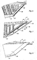
- a frame 59 joins the rear ends E1 and E3 respectively of the upper longitudinal members L1 and lower L3, in a manner that will be described hereinafter with reference to FIGS. Figures 3 to 5 .
- the trailing edge 55 is mounted on the frame 59.
- the trailing edge 55 acts as an aerodynamic closure and drain provided with the pipes 38 for recovering and evacuating leakage liquids, already described above.
- the end portions E4 and E5 of the frame 59 appear, respectively, in connection with the upper rear longitudinal members L1 and lower L3.
- the frame 59 is also linked to the transverse ribs 50, with four ribs in the nonlimiting example illustrated.
- the general shape of the frame 59 is called "Z" because of its inclined central portion and its parallel ends.
- the frame 59 is said to be structural because it participates in the overall behavior of the APF 5. It is structured in the form of an open U-shaped profile in the example, profiled turned towards the outside of the fairing 5.
- L frame comes at the end E5, to fit in longitudinal continuity of the lower longitudinal members L3, between a corresponding end portion P3 of the lower longitudinal members L3 and fifth ends of transverse ribs 50. This embedding is consolidated by bolting between the ends 5e and the lower longitudinal members L3 through a floor 10.
- the frame 59 extends between the lower longitudinal members L3 and the upper longitudinal members L1 on a rectilinear central portion 29, inclined with respect to its end E5 and to the longitudinal members. This frame 59 comes in end E4 in continuity against a portion P1 of the upper longitudinal members L1, E4 being parallel to the other end E5. The area of contact between the frame 59 and the upper longitudinal members L1 results from the inclination of the central portion 29.
- the figure 4 illustrates more precisely the connection between the upper longitudinal members L1 and the frame 59.
- a part 49 attached by welding on the frame 59 is screwed on a bottom deck 20 which connects the longitudinal members L1 in their base lower.
- the "U" profile of the frame 59 appears in this view: it consists of two identical half-shells C9, welded together along a weld center line S9. Floating nuts E9 are inserted all along the flanks F9 of the profile to fix the trailing edge in the manner described below with reference to the figure 7 . Other floating nuts E9 also appear on the longitudinal members L1 to fix the panels of the APF as will be mentioned hereinafter in connection with the figure 8 .
- connection between the frame 59 and the longitudinal members L3 is formed by sinking. This jogging causes a slight deformation of the end portion E5 of the frame 59 due to the spacing "V" of the lower longitudinal members L3.
- These lower longitudinal members L3 are covered by gluing or thermofusion with a thermal protection coating 21 based on aluminum or aluminum. fiber / resin composite material. The rear positioning of the coating 21 is illustrated in figure 6 .
- trailing edge 55 formed of a sheet of titanium bent along an edge A5
- a floating nut alignment E9 provides the connection between each pan 56 of the trailing edge 55 and each sidewall F9 of the frame.
- the portion P1 of the upper longitudinal members L1 in connection with the frame 59 leaves free the end E1 of these longitudinal members so as to allow a consolidated integration of the trailing edge 55 in connection with the end E1 of the upper longitudinal members L1.
- FIG. 8 which illustrates in front view the rear part of an APF5 according to the invention at the end of assembly, also appear the side panels 61 mounted on the side members and the ribs with floating nuts E9 and the protective coating thermal 21.
- the profile of the frame 59 may be of various shape in section, for example in "V” or "W".
- the materials used for the APF may be made of aluminum or composite material.
Landscapes
- Engineering & Computer Science (AREA)
- Aviation & Aerospace Engineering (AREA)
- Chemical & Material Sciences (AREA)
- Combustion & Propulsion (AREA)
- Mechanical Engineering (AREA)
- Body Structure For Vehicles (AREA)
- Connection Of Plates (AREA)
- Pressure Welding/Diffusion-Bonding (AREA)
- Laminated Bodies (AREA)
Claims (9)
- Hinterseitige aerodynamische Verkleidung (5) eines Befestigungspylons (1) eines Flugzeugtriebwerks (4), umfassend obere Längsträger (L1), Querrippen (50), untere Längsträger (L3) sowie einen Leckagerand (55), wobei die oberen Längsträger (L1) und die unteren Längsträger (L3) "V-förmig" auf der Seite des Leckagerandes (55) aneinanderstoßen, dadurch gekennzeichnet, dass ein Strukturgerüst (59) am Leckagerand nach einem nach außen zur Verkleidung (5) hin offenen Profil ausgeführt ist, und dass das Gerüst (59) an einem ersten Endabschnitt (E5) in Längsausrichtung zu den unteren Längsträgern (L3) zwischen einem Endabschnitt (P3) der unteren Längsträger (L3) und Enden (5e) mindestens einer Querrippe (50) eingesetzt wird, sich zwischen den unteren Längsträgern (L3) und den oberen Längsträgern (L1) auf einem geraden zentralen, zum ersten Endabschnitt (E5) geneigten Abschnitt (29) erstreckt, wobei dieser zentrale Abschnitt (29) geeignet ist, den Leckagerand (55) aufzunehmen, und an einem zweiten Endabschnitt (E4) in Ausrichtung an einem Abschnitt (P1) der oberen Längsträger (L1) parallel zum ersten Ende (E5) zur Anlage gelangt.
- Verkleidung nach Anspruch 1, bei der der Verbindungsabschnitt (P1) der oberen Längsträger (L1) mit dem Gerüst (59) das Ende (E1) der oberen Längsträger frei lässt, um eine feste Eingliederung des Leckagerandes in Verbindung mit dem Ende (E1) der oberen Längsträger zu ermöglichen.
- Verkleidung nach einem der Ansprüche 1 oder 2, bei der der erste Endabschnitt (E5) des Gerüsts (59) durch eine Befestigung der Einheit Rippe(n)-Gerüst-Längsträger befestigt ist.
- Verkleidung nach einem der vorhergehenden Ansprüche, bei der das Gerüst (59) durch Verschweißen von zwei Halbschalen (C9), um ein "U"-Profil zu bilden, hergestellt ist.
- Verkleidung nach einem der vorhergehenden Ansprüche, bei der das Einsetzen des Gerüsts (59) auf die unteren Längsträger (L3) durch Stechen des Gerüsts auf diese Längsträger erfolgt.
- Verkleidung nach einem der vorhergehenden Ansprüche, bei der der Leckagerand (55) von einer längs entlang einer Kante (A5) gefalzten Blechfolie gebildet ist, um zwei in das Gerüst integrierte Flächen (56) zu bilden, um entlang der gesamten Seiten (F9) des Profils des Gerüsts (59) befestigt zu werden.
- Verkleidung nach einem der vorhergehenden Ansprüche, bei der das Gerüst (59) von zwei identischen Halbschalen (C9) gebildet ist, die längs miteinander entlang einer Mittellinie (S9) verschweißt sind.
- Verkleidung nach einem der vorhergehenden Ansprüche, bei der ein Drain abnehmbar durch einen Ausschnitt des Leckagerandes (55) auf der Seite der oberen Längsträger (L1) integriert ist.
- Verkleidung nach einem der vorhergehenden Ansprüche, bei der Seitenplatten (61) sowie eine Wärmeschutzabdeckung (21) mit den Rippen (50) bzw. den unteren Längsträgern (L3) verbunden sind.
Applications Claiming Priority (1)
| Application Number | Priority Date | Filing Date | Title |
|---|---|---|---|
| FR1160650A FR2982845B1 (fr) | 2011-11-22 | 2011-11-22 | Carenage aerodynamique arriere de mat de moteur d'aeronef |
Publications (2)
| Publication Number | Publication Date |
|---|---|
| EP2597039A1 EP2597039A1 (de) | 2013-05-29 |
| EP2597039B1 true EP2597039B1 (de) | 2014-11-05 |
Family
ID=47177848
Family Applications (1)
| Application Number | Title | Priority Date | Filing Date |
|---|---|---|---|
| EP12193413.7A Not-in-force EP2597039B1 (de) | 2011-11-22 | 2012-11-20 | Hinterseitige aerodynamische Verkleidung eines Flugzeugtriebwerkspylons |
Country Status (4)
| Country | Link |
|---|---|
| US (1) | US8800917B2 (de) |
| EP (1) | EP2597039B1 (de) |
| CN (1) | CN103129739B (de) |
| FR (1) | FR2982845B1 (de) |
Families Citing this family (12)
| Publication number | Priority date | Publication date | Assignee | Title |
|---|---|---|---|---|
| US9555871B2 (en) * | 2012-03-05 | 2017-01-31 | The Boeing Company | Two-surface sandwich structure for accommodating in-plane expansion of one of the surfaces relative to the opposing surface |
| FR2988688B1 (fr) * | 2012-03-27 | 2014-05-09 | Airbus Operations Sas | Carenage aerodynamique arriere a tenue en temperature amelioree pour mat d'accrochage d'ensemble propulsif d'aeronef |
| CN103612746B (zh) * | 2013-10-24 | 2016-09-21 | 中国商用飞机有限责任公司 | 翼吊布局飞机中吊挂的整流罩结构 |
| FR3013679B1 (fr) | 2013-11-25 | 2015-11-27 | Airbus Operations Sas | Carenage aerodynamique divise en sous-parties |
| JP6317946B2 (ja) * | 2014-02-18 | 2018-04-25 | 三菱航空機株式会社 | 航空機 |
| JP6419437B2 (ja) * | 2014-02-28 | 2018-11-07 | 三菱航空機株式会社 | 航空機のエンジンパイロンおよび航空機 |
| US9725183B2 (en) * | 2015-06-22 | 2017-08-08 | Rohr, Inc. | Pylon with noise attenuating fairing |
| US10502091B2 (en) | 2016-12-12 | 2019-12-10 | United Technologies Corporation | Sync ring assembly and associated clevis including a rib |
| US10766600B2 (en) * | 2017-07-28 | 2020-09-08 | The Boeing Company | Articulation assemblies for retracting aircraft flap support fairings and related methods |
| FR3083776B1 (fr) * | 2018-07-12 | 2021-05-14 | Airbus Operations Sas | Mat d'accrochage pour un turboreacteur d'un aeronef comportant une structure particuliere |
| US12024305B2 (en) | 2021-10-28 | 2024-07-02 | Honeywell International Inc. | Pylon system for coupling engine to vehicle |
| US20240343409A1 (en) * | 2023-04-14 | 2024-10-17 | Airbus Operations Sas | Aircraft having a dihydrogen supply pipe seated in a corridor delimited between two spars of a wing |
Family Cites Families (21)
| Publication number | Priority date | Publication date | Assignee | Title |
|---|---|---|---|---|
| US4238092A (en) * | 1978-08-17 | 1980-12-09 | Rohr Industries, Inc. | Accessory for a turbine engine |
| US4802823A (en) * | 1988-05-09 | 1989-02-07 | Avco Corporation | Stress relief support structures and assemblies |
| FR2832011B1 (fr) * | 2001-11-05 | 2005-05-20 | Airbus France | Reseau de communication de type ethernet full duplex commute et procede de mise en oeuvre de celui-ci |
| US6983912B2 (en) * | 2002-04-30 | 2006-01-10 | The Boeing Company | Hybrid exhaust heat shield for pylon mounted gas turbine engines |
| EP1561997A1 (de) * | 2004-01-27 | 2005-08-10 | Siemens Aktiengesellschaft | Hitzeschild |
| US7850058B2 (en) * | 2004-03-31 | 2010-12-14 | The Boeing Company | Superplastic forming of titanium assemblies |
| FR2889163B1 (fr) * | 2005-07-29 | 2007-09-07 | Airbus France Sas | Ensemble pour aeronef comprenant un element de voilure ainsi qu'un mat d'accrochage |
| FR2891250B1 (fr) * | 2005-09-28 | 2007-10-26 | Airbus France Sas | Ensemble moteur pour aeronef comprenant un moteur ainsi qu'un mat d'accrochage d'un tel moteur |
| FR2891248B1 (fr) * | 2005-09-28 | 2009-05-01 | Airbus France Sas | Ensemble moteur pour aeronef comprenant un moteur ainsi qu'un mat d'accrochage d'un tel moteur |
| FR2891251B1 (fr) * | 2005-09-28 | 2009-04-03 | Airbus France Sas | Mat d'accrochage de moteur pour aeronef |
| FR2901243B1 (fr) * | 2006-05-16 | 2008-06-27 | Airbus France Sas | Dispositif d'accrochage d'un moteur d'aeronef |
| FR2905930B1 (fr) * | 2006-09-18 | 2009-05-15 | Airbus France Sa | Generateur de tourbillon en sortie de gaz chauds |
| FR2913665B1 (fr) * | 2007-03-16 | 2009-06-05 | Airbus France Sa | Carenage aerodynamique arriere inferieur pour dispositif d'accrochage d'un moteur d'aeronef |
| FR2920623B1 (fr) * | 2007-09-03 | 2011-09-23 | Airbus France | Dispositif de commutation de trames pour reseau afdx. |
| FR2921342B1 (fr) * | 2007-09-20 | 2010-03-12 | Airbus France | Carenage aerodynamique arriere inferieur pour dispositif d'accrochage d'un moteur d'aeronef |
| US7943227B2 (en) * | 2007-10-11 | 2011-05-17 | The Boeing Company | Ceramic heat shield |
| FR2929245B1 (fr) * | 2008-03-28 | 2010-05-14 | Aircelle Sa | Structure primaire d'un mat d'accrochage. |
| FR2960523B1 (fr) * | 2010-05-27 | 2012-06-29 | Airbus Operations Sas | Procede de fabrication par formage superplastique et par eclissage d'une nervure pour carenage aerodynamique de mat d'accrochage de moteur d'aeronef |
| US9151171B2 (en) * | 2010-08-27 | 2015-10-06 | Siemens Energy, Inc. | Stepped inlet ring for a transition downstream from combustor basket in a combustion turbine engine |
| FR2965548B1 (fr) * | 2010-10-01 | 2012-10-19 | Airbus Operations Sas | Mat d'accrochage d'un moteur d'aeronef comprenant deux attaches voilure avant a pions de cisaillement orthogonaux |
| FR2981636B1 (fr) * | 2011-10-19 | 2013-12-27 | Airbus Operations Sas | Carenage aerodynamique arriere pour dispositif d'accrochage d'un moteur d'aeronef, comprenant un bouclier thermique capable de se dilater librement |
-
2011
- 2011-11-22 FR FR1160650A patent/FR2982845B1/fr not_active Expired - Fee Related
-
2012
- 2012-11-20 CN CN201210473635.4A patent/CN103129739B/zh not_active Expired - Fee Related
- 2012-11-20 EP EP12193413.7A patent/EP2597039B1/de not_active Not-in-force
- 2012-11-20 US US13/682,138 patent/US8800917B2/en active Active
Also Published As
| Publication number | Publication date |
|---|---|
| CN103129739B (zh) | 2016-04-06 |
| CN103129739A (zh) | 2013-06-05 |
| FR2982845A1 (fr) | 2013-05-24 |
| US8800917B2 (en) | 2014-08-12 |
| FR2982845B1 (fr) | 2013-12-20 |
| US20130221157A1 (en) | 2013-08-29 |
| EP2597039A1 (de) | 2013-05-29 |
Similar Documents
| Publication | Publication Date | Title |
|---|---|---|
| EP2597039A1 (de) | Hinterseitige aerodynamische Verkleidung eines Flugzeugtriebswerkspylons | |
| EP2190739B1 (de) | Untere hinterseitige aerodynamische verkleidung für eine flugzeugmotorbefestigungsvorrichtung | |
| EP2146898B1 (de) | Hintere, untere aerodynamische verkleidung für die befestigungsvorrichtung eines flugzeugmotors | |
| FR3040076A1 (fr) | Ensemble moteur pour aeronef comprenant une structure primaire de mat d'accrochage equipee d'une extension de caisson comprenant deux parties en forme globale d'arceau | |
| EP2139769B1 (de) | Befestigung für pylonkasten an flügeln, festklemmen einer seitenplatte des kastens | |
| EP2185413B1 (de) | An der befestigungstriebwerksaufhängung und am gondellufteinlass angebrachtes gestell zum halten eines fan-coils | |
| EP2554478B1 (de) | Schwenkbare Verkleidung für Triebwerksvekleidungen getragen von diesen Triebwerksvekleidungen im geschlossenen Zustand | |
| EP3505448B1 (de) | Einheit für ein luftfahrzeug, die eine primärstruktur eines aufhängungsmasts umfasst, die an einem flügelkasten mithilfe von anschlüssen reduzierten volumens in der vorderkantenzone befestigt ist | |
| EP3757012B1 (de) | Flugzeugantriebssystem mit verbesserter primärmaststruktur und vorderer triebwerksbefestigung | |
| CA2781013C (fr) | Carenage aerodynamique arriere d'un mat de liaison d'un moteur d'aeronef | |
| FR2981636A1 (fr) | Carenage aerodynamique arriere pour dispositif d'accrochage d'un moteur d'aeronef, comprenant un bouclier thermique capable de se dilater librement | |
| FR3020343A1 (fr) | Ensemble pour aeronef comprenant une structure primaire de mat d'accrochage constituee par trois elements independants | |
| FR2943039A1 (fr) | Avion a empennage queue-de-morue et moteur arriere. | |
| FR3015433A1 (fr) | Ensemble pour aeronef comprenant un mat d'accrochage integre a la nacelle et agence en partie arriere du fuselage | |
| EP3505439B1 (de) | Einheit für ein luftfahrzeug, die eine primärstruktur eines aufhängungsmasts umfasst, die an einem flügelkasten durch befestigungselemente befestigt ist und im vorderkantenbereich ein reduziertes volumen aufweist | |
| WO2015067891A2 (fr) | Ensemble pour aeronef comprenant une ferrure fixee sur la partie extrados d'un caisson de voilure, pour le montage d'un mat d'accrochage sur ce caisson de voilure | |
| FR3041935A1 (fr) | Ensemble moteur pour aeronef comprenant au moins deux attaches moteur arriere decalees axialement l'une de l'autre | |
| EP3521173B1 (de) | Einheit für luftfahrzeug, die eine primärstruktur einer aufhängesäule umfasst, die an einem fahrwerkskasten mithilfe einer verschraubten verbindung befestigt ist | |
| FR2887521A1 (fr) | Ensemble moteur pour aeronef comprenant un moteur ainsi qu'un dispositif d'accrochage d'un tel moteur | |
| EP3489147A1 (de) | Einheit für luftfahrzeug, die eine primärstruktur einer aufhängesäule umfasst, die an einem fahrwerkskasten mithilfe von teilweise in der primärstruktur verankerten anschlüssen befestigt ist | |
| FR3020798A1 (fr) | Ensemble propulsif pour aeronef comprenant un conduit formant barriere thermique integre au caisson de la structure rigide du mat d'accrochage | |
| EP2644505B1 (de) | Aerodynamische Heckverkleidung mit verbesserter Temperaturresistenz für Ausleger einer Antriebseinheit eines Luftfahrzeugs | |
| FR3121428A1 (fr) | Mât réacteur d’aéronef comportant un ensemble mobile de capots | |
| EP3728041B1 (de) | Öffnende triebwerksverkleidungsanordnung und einsatzmechanismus | |
| FR3013678A1 (fr) | Carenage aerodynamique |
Legal Events
| Date | Code | Title | Description |
|---|---|---|---|
| PUAI | Public reference made under article 153(3) epc to a published international application that has entered the european phase |
Free format text: ORIGINAL CODE: 0009012 |
|
| 17P | Request for examination filed |
Effective date: 20121120 |
|
| AK | Designated contracting states |
Kind code of ref document: A1 Designated state(s): AL AT BE BG CH CY CZ DE DK EE ES FI FR GB GR HR HU IE IS IT LI LT LU LV MC MK MT NL NO PL PT RO RS SE SI SK SM TR |
|
| AX | Request for extension of the european patent |
Extension state: BA ME |
|
| GRAP | Despatch of communication of intention to grant a patent |
Free format text: ORIGINAL CODE: EPIDOSNIGR1 |
|
| INTG | Intention to grant announced |
Effective date: 20140821 |
|
| GRAS | Grant fee paid |
Free format text: ORIGINAL CODE: EPIDOSNIGR3 |
|
| GRAA | (expected) grant |
Free format text: ORIGINAL CODE: 0009210 |
|
| AK | Designated contracting states |
Kind code of ref document: B1 Designated state(s): AL AT BE BG CH CY CZ DE DK EE ES FI FR GB GR HR HU IE IS IT LI LT LU LV MC MK MT NL NO PL PT RO RS SE SI SK SM TR |
|
| REG | Reference to a national code |
Ref country code: GB Ref legal event code: FG4D Free format text: NOT ENGLISH |
|
| REG | Reference to a national code |
Ref country code: CH Ref legal event code: EP |
|
| REG | Reference to a national code |
Ref country code: AT Ref legal event code: REF Ref document number: 694462 Country of ref document: AT Kind code of ref document: T Effective date: 20141115 |
|
| REG | Reference to a national code |
Ref country code: IE Ref legal event code: FG4D Free format text: LANGUAGE OF EP DOCUMENT: FRENCH |
|
| REG | Reference to a national code |
Ref country code: DE Ref legal event code: R096 Ref document number: 602012003665 Country of ref document: DE Effective date: 20141224 |
|
| REG | Reference to a national code |
Ref country code: AT Ref legal event code: MK05 Ref document number: 694462 Country of ref document: AT Kind code of ref document: T Effective date: 20141105 |
|
| REG | Reference to a national code |
Ref country code: NL Ref legal event code: VDEP Effective date: 20141105 |
|
| REG | Reference to a national code |
Ref country code: LT Ref legal event code: MG4D |
|
| PG25 | Lapsed in a contracting state [announced via postgrant information from national office to epo] |
Ref country code: NL Free format text: LAPSE BECAUSE OF FAILURE TO SUBMIT A TRANSLATION OF THE DESCRIPTION OR TO PAY THE FEE WITHIN THE PRESCRIBED TIME-LIMIT Effective date: 20141105 Ref country code: LT Free format text: LAPSE BECAUSE OF FAILURE TO SUBMIT A TRANSLATION OF THE DESCRIPTION OR TO PAY THE FEE WITHIN THE PRESCRIBED TIME-LIMIT Effective date: 20141105 Ref country code: ES Free format text: LAPSE BECAUSE OF FAILURE TO SUBMIT A TRANSLATION OF THE DESCRIPTION OR TO PAY THE FEE WITHIN THE PRESCRIBED TIME-LIMIT Effective date: 20141105 Ref country code: NO Free format text: LAPSE BECAUSE OF FAILURE TO SUBMIT A TRANSLATION OF THE DESCRIPTION OR TO PAY THE FEE WITHIN THE PRESCRIBED TIME-LIMIT Effective date: 20150205 Ref country code: IS Free format text: LAPSE BECAUSE OF FAILURE TO SUBMIT A TRANSLATION OF THE DESCRIPTION OR TO PAY THE FEE WITHIN THE PRESCRIBED TIME-LIMIT Effective date: 20150305 Ref country code: FI Free format text: LAPSE BECAUSE OF FAILURE TO SUBMIT A TRANSLATION OF THE DESCRIPTION OR TO PAY THE FEE WITHIN THE PRESCRIBED TIME-LIMIT Effective date: 20141105 Ref country code: PT Free format text: LAPSE BECAUSE OF FAILURE TO SUBMIT A TRANSLATION OF THE DESCRIPTION OR TO PAY THE FEE WITHIN THE PRESCRIBED TIME-LIMIT Effective date: 20150305 |
|
| PG25 | Lapsed in a contracting state [announced via postgrant information from national office to epo] |
Ref country code: AT Free format text: LAPSE BECAUSE OF FAILURE TO SUBMIT A TRANSLATION OF THE DESCRIPTION OR TO PAY THE FEE WITHIN THE PRESCRIBED TIME-LIMIT Effective date: 20141105 Ref country code: PL Free format text: LAPSE BECAUSE OF FAILURE TO SUBMIT A TRANSLATION OF THE DESCRIPTION OR TO PAY THE FEE WITHIN THE PRESCRIBED TIME-LIMIT Effective date: 20141105 Ref country code: CY Free format text: LAPSE BECAUSE OF FAILURE TO SUBMIT A TRANSLATION OF THE DESCRIPTION OR TO PAY THE FEE WITHIN THE PRESCRIBED TIME-LIMIT Effective date: 20141105 Ref country code: HR Free format text: LAPSE BECAUSE OF FAILURE TO SUBMIT A TRANSLATION OF THE DESCRIPTION OR TO PAY THE FEE WITHIN THE PRESCRIBED TIME-LIMIT Effective date: 20141105 Ref country code: LV Free format text: LAPSE BECAUSE OF FAILURE TO SUBMIT A TRANSLATION OF THE DESCRIPTION OR TO PAY THE FEE WITHIN THE PRESCRIBED TIME-LIMIT Effective date: 20141105 Ref country code: SE Free format text: LAPSE BECAUSE OF FAILURE TO SUBMIT A TRANSLATION OF THE DESCRIPTION OR TO PAY THE FEE WITHIN THE PRESCRIBED TIME-LIMIT Effective date: 20141105 Ref country code: GR Free format text: LAPSE BECAUSE OF FAILURE TO SUBMIT A TRANSLATION OF THE DESCRIPTION OR TO PAY THE FEE WITHIN THE PRESCRIBED TIME-LIMIT Effective date: 20150206 Ref country code: RS Free format text: LAPSE BECAUSE OF FAILURE TO SUBMIT A TRANSLATION OF THE DESCRIPTION OR TO PAY THE FEE WITHIN THE PRESCRIBED TIME-LIMIT Effective date: 20141105 |
|
| PG25 | Lapsed in a contracting state [announced via postgrant information from national office to epo] |
Ref country code: BE Free format text: LAPSE BECAUSE OF NON-PAYMENT OF DUE FEES Effective date: 20141130 |
|
| PG25 | Lapsed in a contracting state [announced via postgrant information from national office to epo] |
Ref country code: CZ Free format text: LAPSE BECAUSE OF FAILURE TO SUBMIT A TRANSLATION OF THE DESCRIPTION OR TO PAY THE FEE WITHIN THE PRESCRIBED TIME-LIMIT Effective date: 20141105 Ref country code: EE Free format text: LAPSE BECAUSE OF FAILURE TO SUBMIT A TRANSLATION OF THE DESCRIPTION OR TO PAY THE FEE WITHIN THE PRESCRIBED TIME-LIMIT Effective date: 20141105 Ref country code: SK Free format text: LAPSE BECAUSE OF FAILURE TO SUBMIT A TRANSLATION OF THE DESCRIPTION OR TO PAY THE FEE WITHIN THE PRESCRIBED TIME-LIMIT Effective date: 20141105 Ref country code: DK Free format text: LAPSE BECAUSE OF FAILURE TO SUBMIT A TRANSLATION OF THE DESCRIPTION OR TO PAY THE FEE WITHIN THE PRESCRIBED TIME-LIMIT Effective date: 20141105 |
|
| REG | Reference to a national code |
Ref country code: DE Ref legal event code: R097 Ref document number: 602012003665 Country of ref document: DE |
|
| REG | Reference to a national code |
Ref country code: IE Ref legal event code: MM4A |
|
| PG25 | Lapsed in a contracting state [announced via postgrant information from national office to epo] |
Ref country code: MC Free format text: LAPSE BECAUSE OF FAILURE TO SUBMIT A TRANSLATION OF THE DESCRIPTION OR TO PAY THE FEE WITHIN THE PRESCRIBED TIME-LIMIT Effective date: 20141105 |
|
| PLBE | No opposition filed within time limit |
Free format text: ORIGINAL CODE: 0009261 |
|
| STAA | Information on the status of an ep patent application or granted ep patent |
Free format text: STATUS: NO OPPOSITION FILED WITHIN TIME LIMIT |
|
| 26N | No opposition filed |
Effective date: 20150806 |
|
| PG25 | Lapsed in a contracting state [announced via postgrant information from national office to epo] |
Ref country code: IE Free format text: LAPSE BECAUSE OF NON-PAYMENT OF DUE FEES Effective date: 20141120 |
|
| REG | Reference to a national code |
Ref country code: FR Ref legal event code: PLFP Year of fee payment: 4 |
|
| PG25 | Lapsed in a contracting state [announced via postgrant information from national office to epo] |
Ref country code: IT Free format text: LAPSE BECAUSE OF FAILURE TO SUBMIT A TRANSLATION OF THE DESCRIPTION OR TO PAY THE FEE WITHIN THE PRESCRIBED TIME-LIMIT Effective date: 20141105 |
|
| PG25 | Lapsed in a contracting state [announced via postgrant information from national office to epo] |
Ref country code: SI Free format text: LAPSE BECAUSE OF FAILURE TO SUBMIT A TRANSLATION OF THE DESCRIPTION OR TO PAY THE FEE WITHIN THE PRESCRIBED TIME-LIMIT Effective date: 20141105 |
|
| PG25 | Lapsed in a contracting state [announced via postgrant information from national office to epo] |
Ref country code: RO Free format text: LAPSE BECAUSE OF FAILURE TO SUBMIT A TRANSLATION OF THE DESCRIPTION OR TO PAY THE FEE WITHIN THE PRESCRIBED TIME-LIMIT Effective date: 20141105 |
|
| PG25 | Lapsed in a contracting state [announced via postgrant information from national office to epo] |
Ref country code: BG Free format text: LAPSE BECAUSE OF FAILURE TO SUBMIT A TRANSLATION OF THE DESCRIPTION OR TO PAY THE FEE WITHIN THE PRESCRIBED TIME-LIMIT Effective date: 20141105 |
|
| REG | Reference to a national code |
Ref country code: CH Ref legal event code: PL |
|
| PG25 | Lapsed in a contracting state [announced via postgrant information from national office to epo] |
Ref country code: HU Free format text: LAPSE BECAUSE OF FAILURE TO SUBMIT A TRANSLATION OF THE DESCRIPTION OR TO PAY THE FEE WITHIN THE PRESCRIBED TIME-LIMIT; INVALID AB INITIO Effective date: 20121120 Ref country code: CH Free format text: LAPSE BECAUSE OF NON-PAYMENT OF DUE FEES Effective date: 20151130 Ref country code: LU Free format text: LAPSE BECAUSE OF NON-PAYMENT OF DUE FEES Effective date: 20141120 Ref country code: LI Free format text: LAPSE BECAUSE OF NON-PAYMENT OF DUE FEES Effective date: 20151130 Ref country code: TR Free format text: LAPSE BECAUSE OF FAILURE TO SUBMIT A TRANSLATION OF THE DESCRIPTION OR TO PAY THE FEE WITHIN THE PRESCRIBED TIME-LIMIT Effective date: 20141105 Ref country code: MT Free format text: LAPSE BECAUSE OF FAILURE TO SUBMIT A TRANSLATION OF THE DESCRIPTION OR TO PAY THE FEE WITHIN THE PRESCRIBED TIME-LIMIT Effective date: 20141105 |
|
| REG | Reference to a national code |
Ref country code: FR Ref legal event code: PLFP Year of fee payment: 5 |
|
| PG25 | Lapsed in a contracting state [announced via postgrant information from national office to epo] |
Ref country code: SM Free format text: LAPSE BECAUSE OF FAILURE TO SUBMIT A TRANSLATION OF THE DESCRIPTION OR TO PAY THE FEE WITHIN THE PRESCRIBED TIME-LIMIT Effective date: 20141105 |
|
| REG | Reference to a national code |
Ref country code: FR Ref legal event code: PLFP Year of fee payment: 6 |
|
| PG25 | Lapsed in a contracting state [announced via postgrant information from national office to epo] |
Ref country code: MK Free format text: LAPSE BECAUSE OF FAILURE TO SUBMIT A TRANSLATION OF THE DESCRIPTION OR TO PAY THE FEE WITHIN THE PRESCRIBED TIME-LIMIT Effective date: 20141105 |
|
| PG25 | Lapsed in a contracting state [announced via postgrant information from national office to epo] |
Ref country code: AL Free format text: LAPSE BECAUSE OF FAILURE TO SUBMIT A TRANSLATION OF THE DESCRIPTION OR TO PAY THE FEE WITHIN THE PRESCRIBED TIME-LIMIT Effective date: 20141105 |
|
| PGFP | Annual fee paid to national office [announced via postgrant information from national office to epo] |
Ref country code: GB Payment date: 20231123 Year of fee payment: 12 |
|
| PGFP | Annual fee paid to national office [announced via postgrant information from national office to epo] |
Ref country code: FR Payment date: 20231120 Year of fee payment: 12 Ref country code: DE Payment date: 20231121 Year of fee payment: 12 |
|
| REG | Reference to a national code |
Ref country code: DE Ref legal event code: R119 Ref document number: 602012003665 Country of ref document: DE |
|
| GBPC | Gb: european patent ceased through non-payment of renewal fee |
Effective date: 20241120 |
|
| PG25 | Lapsed in a contracting state [announced via postgrant information from national office to epo] |
Ref country code: DE Free format text: LAPSE BECAUSE OF NON-PAYMENT OF DUE FEES Effective date: 20250603 |
|
| PG25 | Lapsed in a contracting state [announced via postgrant information from national office to epo] |
Ref country code: GB Free format text: LAPSE BECAUSE OF NON-PAYMENT OF DUE FEES Effective date: 20241120 |
|
| PG25 | Lapsed in a contracting state [announced via postgrant information from national office to epo] |
Ref country code: FR Free format text: LAPSE BECAUSE OF NON-PAYMENT OF DUE FEES Effective date: 20241130 |