EP2597026B1 - Liquefied natural gas cargo hold partition structure and partition sheet - Google Patents
Liquefied natural gas cargo hold partition structure and partition sheet Download PDFInfo
- Publication number
- EP2597026B1 EP2597026B1 EP11809776.5A EP11809776A EP2597026B1 EP 2597026 B1 EP2597026 B1 EP 2597026B1 EP 11809776 A EP11809776 A EP 11809776A EP 2597026 B1 EP2597026 B1 EP 2597026B1
- Authority
- EP
- European Patent Office
- Prior art keywords
- barrier
- barrier sheet
- layer
- metal layer
- sheet
- Prior art date
- Legal status (The legal status is an assumption and is not a legal conclusion. Google has not performed a legal analysis and makes no representation as to the accuracy of the status listed.)
- Active
Links
Images


Classifications
-
- B—PERFORMING OPERATIONS; TRANSPORTING
- B63—SHIPS OR OTHER WATERBORNE VESSELS; RELATED EQUIPMENT
- B63B—SHIPS OR OTHER WATERBORNE VESSELS; EQUIPMENT FOR SHIPPING
- B63B3/00—Hulls characterised by their structure or component parts
- B63B3/14—Hull parts
- B63B3/68—Panellings; Linings, e.g. for insulating purposes
-
- B—PERFORMING OPERATIONS; TRANSPORTING
- B65—CONVEYING; PACKING; STORING; HANDLING THIN OR FILAMENTARY MATERIAL
- B65D—CONTAINERS FOR STORAGE OR TRANSPORT OF ARTICLES OR MATERIALS, e.g. BAGS, BARRELS, BOTTLES, BOXES, CANS, CARTONS, CRATES, DRUMS, JARS, TANKS, HOPPERS, FORWARDING CONTAINERS; ACCESSORIES, CLOSURES, OR FITTINGS THEREFOR; PACKAGING ELEMENTS; PACKAGES
- B65D90/00—Component parts, details or accessories for large containers
- B65D90/02—Wall construction
- B65D90/08—Interconnections of wall parts; Sealing means therefor
-
- B—PERFORMING OPERATIONS; TRANSPORTING
- B32—LAYERED PRODUCTS
- B32B—LAYERED PRODUCTS, i.e. PRODUCTS BUILT-UP OF STRATA OF FLAT OR NON-FLAT, e.g. CELLULAR OR HONEYCOMB, FORM
- B32B15/00—Layered products comprising a layer of metal
- B32B15/14—Layered products comprising a layer of metal next to a fibrous or filamentary layer
-
- B—PERFORMING OPERATIONS; TRANSPORTING
- B32—LAYERED PRODUCTS
- B32B—LAYERED PRODUCTS, i.e. PRODUCTS BUILT-UP OF STRATA OF FLAT OR NON-FLAT, e.g. CELLULAR OR HONEYCOMB, FORM
- B32B17/00—Layered products essentially comprising sheet glass, or glass, slag, or like fibres
- B32B17/06—Layered products essentially comprising sheet glass, or glass, slag, or like fibres comprising glass as the main or only constituent of a layer, next to another layer of a specific material
- B32B17/061—Layered products essentially comprising sheet glass, or glass, slag, or like fibres comprising glass as the main or only constituent of a layer, next to another layer of a specific material of metal
-
- B—PERFORMING OPERATIONS; TRANSPORTING
- B63—SHIPS OR OTHER WATERBORNE VESSELS; RELATED EQUIPMENT
- B63B—SHIPS OR OTHER WATERBORNE VESSELS; EQUIPMENT FOR SHIPPING
- B63B25/00—Load-accommodating arrangements, e.g. stowing, trimming; Vessels characterised thereby
- B63B25/02—Load-accommodating arrangements, e.g. stowing, trimming; Vessels characterised thereby for bulk goods
- B63B25/08—Load-accommodating arrangements, e.g. stowing, trimming; Vessels characterised thereby for bulk goods fluid
- B63B25/12—Load-accommodating arrangements, e.g. stowing, trimming; Vessels characterised thereby for bulk goods fluid closed
- B63B25/16—Load-accommodating arrangements, e.g. stowing, trimming; Vessels characterised thereby for bulk goods fluid closed heat-insulated
-
- B—PERFORMING OPERATIONS; TRANSPORTING
- B65—CONVEYING; PACKING; STORING; HANDLING THIN OR FILAMENTARY MATERIAL
- B65D—CONTAINERS FOR STORAGE OR TRANSPORT OF ARTICLES OR MATERIALS, e.g. BAGS, BARRELS, BOTTLES, BOXES, CANS, CARTONS, CRATES, DRUMS, JARS, TANKS, HOPPERS, FORWARDING CONTAINERS; ACCESSORIES, CLOSURES, OR FITTINGS THEREFOR; PACKAGING ELEMENTS; PACKAGES
- B65D90/00—Component parts, details or accessories for large containers
- B65D90/02—Wall construction
- B65D90/06—Coverings, e.g. for insulating purposes
-
- F—MECHANICAL ENGINEERING; LIGHTING; HEATING; WEAPONS; BLASTING
- F17—STORING OR DISTRIBUTING GASES OR LIQUIDS
- F17C—VESSELS FOR CONTAINING OR STORING COMPRESSED, LIQUEFIED OR SOLIDIFIED GASES; FIXED-CAPACITY GAS-HOLDERS; FILLING VESSELS WITH, OR DISCHARGING FROM VESSELS, COMPRESSED, LIQUEFIED, OR SOLIDIFIED GASES
- F17C13/00—Details of vessels or of the filling or discharging of vessels
- F17C13/001—Thermal insulation specially adapted for cryogenic vessels
-
- F—MECHANICAL ENGINEERING; LIGHTING; HEATING; WEAPONS; BLASTING
- F17—STORING OR DISTRIBUTING GASES OR LIQUIDS
- F17C—VESSELS FOR CONTAINING OR STORING COMPRESSED, LIQUEFIED OR SOLIDIFIED GASES; FIXED-CAPACITY GAS-HOLDERS; FILLING VESSELS WITH, OR DISCHARGING FROM VESSELS, COMPRESSED, LIQUEFIED, OR SOLIDIFIED GASES
- F17C3/00—Vessels not under pressure
- F17C3/02—Vessels not under pressure with provision for thermal insulation
- F17C3/025—Bulk storage in barges or on ships
- F17C3/027—Wallpanels for so-called membrane tanks
-
- B—PERFORMING OPERATIONS; TRANSPORTING
- B32—LAYERED PRODUCTS
- B32B—LAYERED PRODUCTS, i.e. PRODUCTS BUILT-UP OF STRATA OF FLAT OR NON-FLAT, e.g. CELLULAR OR HONEYCOMB, FORM
- B32B2250/00—Layers arrangement
- B32B2250/03—3 layers
-
- F—MECHANICAL ENGINEERING; LIGHTING; HEATING; WEAPONS; BLASTING
- F17—STORING OR DISTRIBUTING GASES OR LIQUIDS
- F17C—VESSELS FOR CONTAINING OR STORING COMPRESSED, LIQUEFIED OR SOLIDIFIED GASES; FIXED-CAPACITY GAS-HOLDERS; FILLING VESSELS WITH, OR DISCHARGING FROM VESSELS, COMPRESSED, LIQUEFIED, OR SOLIDIFIED GASES
- F17C2201/00—Vessel construction, in particular geometry, arrangement or size
- F17C2201/01—Shape
- F17C2201/0147—Shape complex
- F17C2201/0157—Polygonal
-
- F—MECHANICAL ENGINEERING; LIGHTING; HEATING; WEAPONS; BLASTING
- F17—STORING OR DISTRIBUTING GASES OR LIQUIDS
- F17C—VESSELS FOR CONTAINING OR STORING COMPRESSED, LIQUEFIED OR SOLIDIFIED GASES; FIXED-CAPACITY GAS-HOLDERS; FILLING VESSELS WITH, OR DISCHARGING FROM VESSELS, COMPRESSED, LIQUEFIED, OR SOLIDIFIED GASES
- F17C2201/00—Vessel construction, in particular geometry, arrangement or size
- F17C2201/05—Size
- F17C2201/052—Size large (>1000 m3)
-
- F—MECHANICAL ENGINEERING; LIGHTING; HEATING; WEAPONS; BLASTING
- F17—STORING OR DISTRIBUTING GASES OR LIQUIDS
- F17C—VESSELS FOR CONTAINING OR STORING COMPRESSED, LIQUEFIED OR SOLIDIFIED GASES; FIXED-CAPACITY GAS-HOLDERS; FILLING VESSELS WITH, OR DISCHARGING FROM VESSELS, COMPRESSED, LIQUEFIED, OR SOLIDIFIED GASES
- F17C2203/00—Vessel construction, in particular walls or details thereof
- F17C2203/03—Thermal insulations
- F17C2203/0304—Thermal insulations by solid means
- F17C2203/0358—Thermal insulations by solid means in form of panels
-
- F—MECHANICAL ENGINEERING; LIGHTING; HEATING; WEAPONS; BLASTING
- F17—STORING OR DISTRIBUTING GASES OR LIQUIDS
- F17C—VESSELS FOR CONTAINING OR STORING COMPRESSED, LIQUEFIED OR SOLIDIFIED GASES; FIXED-CAPACITY GAS-HOLDERS; FILLING VESSELS WITH, OR DISCHARGING FROM VESSELS, COMPRESSED, LIQUEFIED, OR SOLIDIFIED GASES
- F17C2203/00—Vessel construction, in particular walls or details thereof
- F17C2203/06—Materials for walls or layers thereof; Properties or structures of walls or their materials
- F17C2203/0602—Wall structures; Special features thereof
-
- F—MECHANICAL ENGINEERING; LIGHTING; HEATING; WEAPONS; BLASTING
- F17—STORING OR DISTRIBUTING GASES OR LIQUIDS
- F17C—VESSELS FOR CONTAINING OR STORING COMPRESSED, LIQUEFIED OR SOLIDIFIED GASES; FIXED-CAPACITY GAS-HOLDERS; FILLING VESSELS WITH, OR DISCHARGING FROM VESSELS, COMPRESSED, LIQUEFIED, OR SOLIDIFIED GASES
- F17C2203/00—Vessel construction, in particular walls or details thereof
- F17C2203/06—Materials for walls or layers thereof; Properties or structures of walls or their materials
- F17C2203/0602—Wall structures; Special features thereof
- F17C2203/0612—Wall structures
- F17C2203/0626—Multiple walls
- F17C2203/0631—Three or more walls
-
- F—MECHANICAL ENGINEERING; LIGHTING; HEATING; WEAPONS; BLASTING
- F17—STORING OR DISTRIBUTING GASES OR LIQUIDS
- F17C—VESSELS FOR CONTAINING OR STORING COMPRESSED, LIQUEFIED OR SOLIDIFIED GASES; FIXED-CAPACITY GAS-HOLDERS; FILLING VESSELS WITH, OR DISCHARGING FROM VESSELS, COMPRESSED, LIQUEFIED, OR SOLIDIFIED GASES
- F17C2203/00—Vessel construction, in particular walls or details thereof
- F17C2203/06—Materials for walls or layers thereof; Properties or structures of walls or their materials
- F17C2203/0634—Materials for walls or layers thereof
- F17C2203/0636—Metals
-
- F—MECHANICAL ENGINEERING; LIGHTING; HEATING; WEAPONS; BLASTING
- F17—STORING OR DISTRIBUTING GASES OR LIQUIDS
- F17C—VESSELS FOR CONTAINING OR STORING COMPRESSED, LIQUEFIED OR SOLIDIFIED GASES; FIXED-CAPACITY GAS-HOLDERS; FILLING VESSELS WITH, OR DISCHARGING FROM VESSELS, COMPRESSED, LIQUEFIED, OR SOLIDIFIED GASES
- F17C2203/00—Vessel construction, in particular walls or details thereof
- F17C2203/06—Materials for walls or layers thereof; Properties or structures of walls or their materials
- F17C2203/0634—Materials for walls or layers thereof
- F17C2203/0636—Metals
- F17C2203/0639—Steels
- F17C2203/0643—Stainless steels
-
- F—MECHANICAL ENGINEERING; LIGHTING; HEATING; WEAPONS; BLASTING
- F17—STORING OR DISTRIBUTING GASES OR LIQUIDS
- F17C—VESSELS FOR CONTAINING OR STORING COMPRESSED, LIQUEFIED OR SOLIDIFIED GASES; FIXED-CAPACITY GAS-HOLDERS; FILLING VESSELS WITH, OR DISCHARGING FROM VESSELS, COMPRESSED, LIQUEFIED, OR SOLIDIFIED GASES
- F17C2203/00—Vessel construction, in particular walls or details thereof
- F17C2203/06—Materials for walls or layers thereof; Properties or structures of walls or their materials
- F17C2203/0634—Materials for walls or layers thereof
- F17C2203/0636—Metals
- F17C2203/0646—Aluminium
-
- F—MECHANICAL ENGINEERING; LIGHTING; HEATING; WEAPONS; BLASTING
- F17—STORING OR DISTRIBUTING GASES OR LIQUIDS
- F17C—VESSELS FOR CONTAINING OR STORING COMPRESSED, LIQUEFIED OR SOLIDIFIED GASES; FIXED-CAPACITY GAS-HOLDERS; FILLING VESSELS WITH, OR DISCHARGING FROM VESSELS, COMPRESSED, LIQUEFIED, OR SOLIDIFIED GASES
- F17C2203/00—Vessel construction, in particular walls or details thereof
- F17C2203/06—Materials for walls or layers thereof; Properties or structures of walls or their materials
- F17C2203/0634—Materials for walls or layers thereof
- F17C2203/0658—Synthetics
- F17C2203/0663—Synthetics in form of fibers or filaments
-
- F—MECHANICAL ENGINEERING; LIGHTING; HEATING; WEAPONS; BLASTING
- F17—STORING OR DISTRIBUTING GASES OR LIQUIDS
- F17C—VESSELS FOR CONTAINING OR STORING COMPRESSED, LIQUEFIED OR SOLIDIFIED GASES; FIXED-CAPACITY GAS-HOLDERS; FILLING VESSELS WITH, OR DISCHARGING FROM VESSELS, COMPRESSED, LIQUEFIED, OR SOLIDIFIED GASES
- F17C2221/00—Handled fluid, in particular type of fluid
- F17C2221/03—Mixtures
- F17C2221/032—Hydrocarbons
- F17C2221/033—Methane, e.g. natural gas, CNG, LNG, GNL, GNC, PLNG
-
- F—MECHANICAL ENGINEERING; LIGHTING; HEATING; WEAPONS; BLASTING
- F17—STORING OR DISTRIBUTING GASES OR LIQUIDS
- F17C—VESSELS FOR CONTAINING OR STORING COMPRESSED, LIQUEFIED OR SOLIDIFIED GASES; FIXED-CAPACITY GAS-HOLDERS; FILLING VESSELS WITH, OR DISCHARGING FROM VESSELS, COMPRESSED, LIQUEFIED, OR SOLIDIFIED GASES
- F17C2223/00—Handled fluid before transfer, i.e. state of fluid when stored in the vessel or before transfer from the vessel
- F17C2223/01—Handled fluid before transfer, i.e. state of fluid when stored in the vessel or before transfer from the vessel characterised by the phase
- F17C2223/0146—Two-phase
- F17C2223/0153—Liquefied gas, e.g. LPG, GPL
- F17C2223/0161—Liquefied gas, e.g. LPG, GPL cryogenic, e.g. LNG, GNL, PLNG
-
- F—MECHANICAL ENGINEERING; LIGHTING; HEATING; WEAPONS; BLASTING
- F17—STORING OR DISTRIBUTING GASES OR LIQUIDS
- F17C—VESSELS FOR CONTAINING OR STORING COMPRESSED, LIQUEFIED OR SOLIDIFIED GASES; FIXED-CAPACITY GAS-HOLDERS; FILLING VESSELS WITH, OR DISCHARGING FROM VESSELS, COMPRESSED, LIQUEFIED, OR SOLIDIFIED GASES
- F17C2223/00—Handled fluid before transfer, i.e. state of fluid when stored in the vessel or before transfer from the vessel
- F17C2223/03—Handled fluid before transfer, i.e. state of fluid when stored in the vessel or before transfer from the vessel characterised by the pressure level
- F17C2223/033—Small pressure, e.g. for liquefied gas
-
- F—MECHANICAL ENGINEERING; LIGHTING; HEATING; WEAPONS; BLASTING
- F17—STORING OR DISTRIBUTING GASES OR LIQUIDS
- F17C—VESSELS FOR CONTAINING OR STORING COMPRESSED, LIQUEFIED OR SOLIDIFIED GASES; FIXED-CAPACITY GAS-HOLDERS; FILLING VESSELS WITH, OR DISCHARGING FROM VESSELS, COMPRESSED, LIQUEFIED, OR SOLIDIFIED GASES
- F17C2260/00—Purposes of gas storage and gas handling
- F17C2260/03—Dealing with losses
- F17C2260/035—Dealing with losses of fluid
- F17C2260/036—Avoiding leaks
-
- F—MECHANICAL ENGINEERING; LIGHTING; HEATING; WEAPONS; BLASTING
- F17—STORING OR DISTRIBUTING GASES OR LIQUIDS
- F17C—VESSELS FOR CONTAINING OR STORING COMPRESSED, LIQUEFIED OR SOLIDIFIED GASES; FIXED-CAPACITY GAS-HOLDERS; FILLING VESSELS WITH, OR DISCHARGING FROM VESSELS, COMPRESSED, LIQUEFIED, OR SOLIDIFIED GASES
- F17C2270/00—Applications
- F17C2270/01—Applications for fluid transport or storage
- F17C2270/0102—Applications for fluid transport or storage on or in the water
- F17C2270/0105—Ships
-
- F—MECHANICAL ENGINEERING; LIGHTING; HEATING; WEAPONS; BLASTING
- F17—STORING OR DISTRIBUTING GASES OR LIQUIDS
- F17C—VESSELS FOR CONTAINING OR STORING COMPRESSED, LIQUEFIED OR SOLIDIFIED GASES; FIXED-CAPACITY GAS-HOLDERS; FILLING VESSELS WITH, OR DISCHARGING FROM VESSELS, COMPRESSED, LIQUEFIED, OR SOLIDIFIED GASES
- F17C2270/00—Applications
- F17C2270/01—Applications for fluid transport or storage
- F17C2270/0102—Applications for fluid transport or storage on or in the water
- F17C2270/0105—Ships
- F17C2270/0107—Wall panels
Definitions
- a working area 3 is formed between the upper insulation panels 2b between the upper insulation panels 2b.
- a supple or flexible triplex 7 is attached to the top surface of the rigid triplex 5 with an adhesive layer 6 interposed therebetween, and a top bridge pad (not illustrated) is installed.
- the present invention provides a barrier sheet used in a barrier structure of an LNG cargo tank.
- barrier sheet exhibiting a superior mechanical property and a superior sealing characteristic of air tightness and/or liquid tightness to the existing triplex.
- the gap Q or crack is formed in the first and second barrier sheets 300 and 310 constructed in the field due to repeated thermal stresses, gas and/or liquid L stored in the internal space of the cargo tank does not leak.
- Fig. 4 is a graph showing the sealing characteristic of the first and second barrier sheets in accordance with the embodiment of the present invention.
Landscapes
- Engineering & Computer Science (AREA)
- Mechanical Engineering (AREA)
- Chemical & Material Sciences (AREA)
- Combustion & Propulsion (AREA)
- Ocean & Marine Engineering (AREA)
- General Engineering & Computer Science (AREA)
- Physics & Mathematics (AREA)
- Thermal Sciences (AREA)
- Filling Or Discharging Of Gas Storage Vessels (AREA)
Description
- The present invention relates to a barrier structure and barrier sheet for a liquefied natural gas (LNG) cargo tank in LNG carriers to carry LNG or floating offshore platforms to produce and store LNG, and more particularly, to a barrier structure for an LNG cargo tank and a barrier sheet used in the barrier structure.
- In general, LNG refers to a colorless, transparent, and ultra-low temperature liquid obtained by cooling methane-based natural gas at about -163°C and reducing the volume thereof to 1/600.
- LNG carriers to carry LNG or floating offshore platforms to produce and store LNG are provided with a cargo tank capable of containing and storing the LNG at an ultra-low temperature. The LNG cargo tank uses a membrane sheet as a primary barrier and uses a triplex as a secondary barrier. Herein, the triplex for the secondary barrier includes a rigid triplex and a supple triplex. The rigid triplex is previously attached on the surface of an insulation panel during a manufacturing process, and the supple triplex is attached over the rigid triplex through an adhesive such as epoxy glue.
-
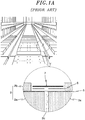
Fig. 1A illustrates a conventional LNG cargo tank 1. Referring toFig. 1A , the cargo tank 1 of a ship or floating offshore platform includesinsulation panels 2 installed on the bottom, ceiling, or walls of the inner surface thereof, wherein theinsulation panel 2 is a kind of radiation panel which is previously manufactured. - The
insulation panels 2 may include alower insulation panel 2a, arigid triplex 5, and anupper insulation panel 2b. Thelower insulation panel 2a is attached and fixed to the walls and the like of the cargo tank 1 through epoxy mastic and stud bolts. The rigid triplex is formed over thelower insulation panel 2a. Theupper insulation panel 2b is disposed over therigid triplex 5 and having a smaller horizontal area than thelower insulation panel 2a. - Further, a
flat joint 2c formed of glass wool and having pores is inserted between thelower insulation panels 2a adjacent to each other. - Further, between the
upper insulation panels 2b is formed aworking area 3. In theworking area 3, a supple orflexible triplex 7 is attached to the top surface of therigid triplex 5 with anadhesive layer 6 interposed therebetween, and a top bridge pad (not illustrated) is installed. - Referring to
Fig. 1B , therigid triplex 5 and thesupple triplex 7 of the conventional LNG cargo tank are formed of composite materials in which a first layer A, a second layer C, and an intermediate B are arranged in a sandwich structure or stacked structure. The first and second layers A and C are formed of glass cloth, and the intermediate layer B is formed of aluminum. In this stacked structure, the intermediate layer B serves for liquid tightness and/or air tightness, and the first and second layers A and C serve to reinforce the intermediate layer B. The first and second layers A and C are attached to each other with the intermediate layer B interposed therebetween, and the outer surface of the first or second layer A or C is exposed to the external environment. - The
rigid triplex 5 of the conventional LNG cargo tank is strictly managed after therigid triplex 5 is manufactured to be coupled to the lower insulation panel 2A. Furthermore, therigid triplex 5 is managed without a flexural deformation even while it is shipped for the use. Therefore, gas and/or liquid L rarely leaks from therigid triplex 5. - On the other hand, although the
supple triplex 7 of the conventional LNG cargo is strictly managed, it is highly likely that gas and/or liquid L leaks from thesupply triplex 7, because thesupple triplex 7 is rolled in a manufacturing process and unrolled to use in the field. - For example, when the secondary barrier is constructed in the cargo tank using the
supple triplex 7, the second layer C of therigid triplex 5 and the first layer A of thesupple triplex 7 are bonded to each other. Under construction, a portion where an interlayer adhesive is not sufficiently impregnated may become weak due to a manufacturing error or careless management of thesupple triplex 7 or the method in which thesupple triplex 7 is rolled and then unrolled to use. In this case, a leakage path may be formed between the second layer C and the intermediate layer B or the first layer A and the intermediate layer B. Along the leakage path formed in such a manner, gas and/or leakage L may leak. The leakage may cause a problem between the first layer A and the intermediate layer B of thesupple triplex 7. - Furthermore, although a crack is formed between the second layer C and the intermediate layer B of the
supple triplex 7 due to repeated thermal loads, liquid tightness and/or air tightness is maintained by the intermediate layer B. Therefore, the gas and/or liquid L inside the cargo tank does not leak toward the pores or the outside of the cargo tank. - On the other hand, the crack may form a leakage path P1 between the first layer A and the intermediate layer B of the
supple triplex 7, and may form another leakage path P2 extended from the leakage path P1 in the thickness direction of the first layer A. That is, when the viscosity of the interlayer adhesive impregnated in the composite materials forming thesupple triplex 7 is high and thesupple triplex 7 is subjected to repeated thermal loads, a crack may occur due to a difference in thermal expansion coefficient between glass cloth and resin, thereby forming the above-described leakage paths P1 and P2. - Therefore, when an operation of attaching the
supple triplex 7 in a strip or belt shape is performed in theworking area 3 described with reference toFig. 1 so as to construct the secondary barrier of the LNG cargo hole, gas and/or liquid L inside the cargo tank may leak to the outside of the cargo tank through the leakage paths P1 and P2 and the pores of the flat joint 2C. Accordingly, the liquid tightness and/or air tightness required by the secondary barrier may not be achieved. - For example, Korean Patent Laid-Open Publication No.
10-2009-0132534 published on December 30, 2009
Another insulation structure of an LNG cargo tank is known fromKR20080104801 - In view of the above, the present invention provides a barrier structure capable of preventing the formation of a leakage path of gas and/or liquid of an LNG cargo tank.
- Further, the present invention provides a barrier sheet used in a barrier structure of an LNG cargo tank.
- In accordance with an aspect of the present invention, there is provided a barrier sheet for a liquefied natural gas (LNG) cargo tank, which includes: first and second metal layers stacked to form a secondary barrier of the LNG cargo tank; and a glass cloth layer interposed between the first and second metal layers and bonded to the first and second metal layers.
- In accordance with an aspect of the present invention, there is provided a barrier structure for an LNG cargo tank, which includes: an insulation panel fixed to the cargo tank and comprising lower insulation panels adjacent to each other with a flat joint interposed therebetween and an upper insulation panel stacked over the lower insulation panels; a first barrier sheet attached between the upper insulation panel and the lower insulation panel so as to form the secondary barrier of the cargo tank; and a second barrier sheet attached on the first barrier sheet over the flat joint, wherein each of the first and second sheets comprises first and second metal layers and a glass cloth layer interposed between the first and second layers.
- Preferably, the first and second metal layers are formed of aluminum and have a thickness of about 0.03 to 0.2mm.
- Preferably, the first and second metal layers are formed of stainless steel and have a thickness of about 0.05 to 0.1mm.
- Preferably, the first and the second barrier sheets are bonded to each other using a liquid adhesive for the secondary barrier or a synthetic resin film having an adhesive applied the surface thereof.
- Preferably, the glass cloth layer is formed of prepreg which is fabric reinforced composite materials.
- Preferably, the glass cloth layer has a thickness of about 0.15 to 0.4mm such that the first and the second barrier sheets satisfy a mechanical property for the secondary barrier.
- In accordance with the embodiments of the present invention, when the secondary barrier of the LNG cargo tank is constructed, the second metal layer in the first barrier sheet and the first metal layer in the second barrier sheet are bonded to each other. Therefore, although an interlayer bonding defect occurs to form a path through which gas and/or liquid may move, the path is prevented from being used as a leakage path of gas and/or liquid. As a result, it is possible to implement a reliable barrier structure from which gas and/or liquid does not leak.
- Further, it is possible to provide the barrier sheet exhibiting a superior mechanical property and a superior sealing characteristic of air tightness and/or liquid tightness to the existing triplex.
- Furthermore, the barrier sheet in accordance with the embodiment of the present invention has an optimized thickness range capable of removing the concern of damage during the manufacturing and handling process and securing flexibility. Therefore, when the secondary barrier of the cargo tank is constructed, the barrier sheet may be bent to correspond to a level difference between the insulation panels. Accordingly, it is easy to deal with the barrier sheet.
-
-
Fig. 1A is a diagram for explaining a barrier structure formed in a conventional LNG cargo tank; -
Fig. 1B is a cross-sectional view of triplexes and insulation panels formed in the barrier structure ofFig. 1A ; -
Fig. 2 illustrates a barrier sheet used in a barrier structure of an LNG cargo tank in accordance with an embodiment of the present invention; -
Fig. 3 is a cross-sectional view of a barrier structure of the LNG cargo tank employing the barrier sheet shown inFig. 2 ; and -
Fig. 4 is a graph showing a sealing characteristic of the barrier sheet shown inFig. 2 . - Hereinafter, a barrier structure and barrier sheet for an LNG cargo tank in accordance with an embodiment of the present invention will be described in detail with reference to
Fig. 2 to Fig. 4 , in which same or like reference numerals refer to the same components throughout the accompanying drawings. - While the embodiments of the present invention have been described, they are exemplary ones only and do intend not to limit the scope of the present invention.
-
Fig. 2 illustrates a barrier sheet used in a barrier structure of an LNG cargo tank in accordance with an embodiment of the present invention. - Referring to
Fig. 2 , abarrier sheet 100 of the LNG cargo tank in accordance with an embodiment of the present invention may have a sandwich structure or stacked structure of thin layers to form a secondary barrier of the LNG cargo tank. That is, thebarrier sheet 100 in accordance with the embodiment may include afirst metal layer 101, aglass cloth layer 102, and asecond metal layer 103, which correspond to the stacked thin layers. - The
barrier sheet 100 may have a thin plate shape such as a belt or strip shape to be coupled to another sheet for the secondary barrier of the LNG cargo tank. - The first and
second metal layers barrier sheet 100 may be formed of aluminum or stainless steel. The first andsecond metal layers - In exemplary embodiment, when the thickness of the first and
second layers second layers second layers barrier sheet 100 rapidly decreases. When the secondary barrier is constructed, it may become difficult to deal with a level difference between top andlower insulation panels - Further, the first and
second metal layers - Therefore, when the manufacturing process, the handling process, and the level difference are considered, it is understood that the numerical values for the thickness of the first and
second metal layers second metal layers Fig. 4 . - Meanwhile, the
glass cloth layer 102 may be interposed between the first andsecond metal layers glass cloth layer 102 may be formed of prepreg which is fiber reinforced composite materials. Further, theglass cloth layer 102 may have an optimized thickness of about 0.15 to 0.4mm such that thebarrier sheet 100 in accordance with the embodiment satisfies a superior mechanical property and an excellent sealing characteristic when the secondary barrier is constructed. -
Fig. 3 is a cross-sectional view of a barrier structure forming the secondary barrier of the LNG cargo tank using the barrier sheet illustrated inFig. 2 . - Referring to
Fig. 3 , the barrier structure in accordance with the embodiment of the present invention includesinsulation panels first barrier sheet 300, and asecond barrier sheet 310. Theinsulation panels lower insulation panels 20 adjacent to each other with a flat joint 22 interposed therebetween and anupper insulation panel 21 stacked over thelower insulation panel 20. Thefirst barrier sheet 300 is attached between the upper andlower insulation panels second barrier sheet 310 is attached on the first barrier sheet over the flat joint 22. - The
first barrier sheet 300 in accordance with the embodiment is strictly managed after thefirst barrier sheet 300 has been previously attached or coupled to the surface of thelower insulation panel 20 so as to have a rigid characteristic, during the manufacturing process. Then, thefirst barrier sheet 300 is managed without a flexural deformation even while it is shipped to the field. Therefore, the above-described leakage path is rarely formed. - Further, the
second barrier sheet 310 having a supple characteristic is manufactured in such a shape as to be rolled and then unrolled for use. Therefore, thesecond barrier sheet 310 may be bonded and attached to thefirst barrier sheet 300 so as to form the secondary barrier of the LNG cargo tank. - Each of the first and
second barrier sheets first metal layer 101, theglass cloth layer 102, and thesecond metal layer 103, as described above with reference toFig. 2 . - As the thicknesses of the first and
second metal layers second barrier sheets second barrier sheets second metal layers barrier sheet 300 may be set to a large value within the above-described thickness range, and the thicknesses of the first andsecond metal layers second barrier sheet 310 may be set to a smaller value than thefirst barrier sheet 300 within the above-described thickness range, which may result in that the first andsecond barrier sheets - Furthermore, when the
second barrier sheet 310 is bonded over thefirst barrier sheet 300 or ends of the barrier sheets are connected and bonded to each other, the barrier sheets may be bonded to each other through anadhesive layer 200. Theadhesive layer 200 may be formed by applying a commercial liquid adhesive for the secondary barrier onto thefirst metal layer 101 in thesecond barrier sheet 310 or thesecond metal layer 103 in thefirst barrier sheet 300 and then heating and pressurizing the applied liquid adhesive using a surface heater such as a ceramic heater (not illustrated). - Alternatively, the
adhesive layer 200 may be formed by bonding an adhesive film in which a synthetic resin film has an adhesive applied the surface thereof, to thefirst metal layer 101 in thesecond barrier sheet 310 or thesecond metal layer 103 in thefirst barrier sheet 300. - According to the above-described barrier structure, when the first and
second barrier sheet second metal layer 103 of thefirst barrier sheet 300 and thefirst metal layer 101 of thesecond barrier sheet 310 are bonded to each other through theadhesive layer 200. When an interlayer adhesion defect occurs in the first andsecond barrier sheets glass cloth layer 102 coupled between the first andsecond metal layers first metal layer 101 and theglass cloth layer 102 or thesecond metal layer 103 and theglass cloth layer 102. - However, although the gap Q or crack is formed in the first and
second barrier sheets - That is because, although the gas and/or liquid L stored in the internal space of the cargo tank may flow between the
first metal layer 101 and theglass cloth layer 102 or thesecond metal layer 103 and theglass cloth layer 102 along the gap Q, thefirst metal layer 101 in thesecond barrier sheet 310 and thesecond metal layer 103 in thefirst barrier sheet 300 are bonded to each other through theadhesive layer 200. - Under the supposition that there are no problems in forming the
adhesive layer 200, liquid tightness and/or air tightness may be maintained by the second andfirst metal layers second barrier sheet adhesive layer 200. Accordingly, gas and/or liquid L does not leak toward the pores of the flat joint 22 or an external space of the cargo tank through the pores of the flat joint 22. - The mechanical properties and sealing characteristics of the first and
second barrier sheets - Table 1 shows the test results of the sample in accordance with the embodiment of the present invention and the triplex for the secondary barrier of the conventional cargo tank. Referring to Table 1, it can be seen that the sample in accordance with the embodiment of the present invention has a much higher tensile strength and a much higher strength corresponding to an elasticity coefficient than the triplex for the secondary barrier of the conventional cargo tank, in both of room temperature and ultra-low temperature environments.
[Table 1] Characteristic Tensile strength Elastic coefficient Warp direction Weft direction Warp direction Weft direction Unit Mpa Mpa Room temperature Prior art 211.3 168.4 10100 8771 Present invention 302.5 25879 Ultra-low temperature Prior art 389.2 335.5 11371 7229 Present invention 461.3 29948 -
Fig. 4 is a graph showing the sealing characteristic of the first and second barrier sheets in accordance with the embodiment of the present invention. - Referring to
Fig. 4 , it can be seen that the sealing characteristic of the sample in accordance with the embodiment hardly change even though repeated thermal loads, for example, 60, 120, or 300 times of thermal loads are repeated, which means that the sample has excellent air tightness and liquid tightness characteristics.
Claims (6)
- A barrier structure for an LNG cargo tank, the barrier structure comprising:an insulation panel (20, 21) fixed to the cargo tank and comprising lower insulation panels (20) adjacent to each other with a flat joint interposed therebetween and an upper insulation panel (21) stacked over the lower insulation panels (20);a first barrier sheet (300) attached between the upper insulation panel (21) and the lower insulation panel (20) so as to form the secondary barrier of the LNG cargo tank;a second barrier sheet (310) attached on the first barrier sheet (300) over the flat joint (22); andan adhesive layer (200) disposed between the first barrier sheet (300) and the second barrier sheet (310) and bonding the first barrier sheet (300) to the second barrier sheet (310),wherein each of the first barrier sheet (300) and the second barrier sheet (310) comprises a first metal layer (101), a second metal layer (103) and a glass cloth layer (102) interposed between the first metal layer (101) and the second metal layer (103), wherein a lower surface of the first metal layer (101) of the first barrier sheet (300) is in contact with the lower insulation panels (20), andwherein an upper surface of the second metal layer (103) of the first barrier sheet (300) is in contact with the upper insulation panels (21) and the adhesive layer (200).
- The barrier structure of claim 1, wherein the first metal layer (101) and the second metal layer (103) are formed of aluminum, and have a thickness of about 0.03 to 0.2mm.
- The barrier structure of claim 1, wherein the first metal layer (101) and second metal layer (103) are formed of stainless steel, and have a thickness of about 0.05 to 0.1mm.
- The barrier structure of claim 1, wherein the adhesive layer (200) is configured as a liquid adhesive for the secondary barrier or a synthetic resin film having an adhesive applied thereon.
- The barrier structure of claim 1, wherein the glass cloth layer (102) is formed of prepreg which is fabric reinforced composite materials.
- The barrier structure of claim 1, wherein the glass cloth layer (102) has a thickness of about 0.15 to 0.4mm such that the first barrier sheet (300) and second barrier sheet (310) satisfy a mechanical property for the secondary barrier.
Applications Claiming Priority (2)
| Application Number | Priority Date | Filing Date | Title |
|---|---|---|---|
| KR1020100071436A KR101215522B1 (en) | 2010-07-23 | 2010-07-23 | Heat insulating structure for barrier of lng cargo |
| PCT/KR2011/001788 WO2012011649A1 (en) | 2010-07-23 | 2011-03-15 | Liquefied natural gas cargo hold partition structure and partition sheet |
Publications (3)
| Publication Number | Publication Date |
|---|---|
| EP2597026A1 EP2597026A1 (en) | 2013-05-29 |
| EP2597026A4 EP2597026A4 (en) | 2015-08-12 |
| EP2597026B1 true EP2597026B1 (en) | 2018-05-09 |
Family
ID=45497041
Family Applications (1)
| Application Number | Title | Priority Date | Filing Date |
|---|---|---|---|
| EP11809776.5A Active EP2597026B1 (en) | 2010-07-23 | 2011-03-15 | Liquefied natural gas cargo hold partition structure and partition sheet |
Country Status (6)
| Country | Link |
|---|---|
| US (1) | US10065796B2 (en) |
| EP (1) | EP2597026B1 (en) |
| JP (1) | JP5476508B2 (en) |
| KR (1) | KR101215522B1 (en) |
| CN (1) | CN103025605B (en) |
| WO (1) | WO2012011649A1 (en) |
Families Citing this family (11)
| Publication number | Priority date | Publication date | Assignee | Title |
|---|---|---|---|---|
| US10124448B2 (en) * | 2011-12-31 | 2018-11-13 | Forge Tech, Inc. | Apparatus for repairing and improving structural integrity of storage tanks |
| KR101358218B1 (en) * | 2012-02-16 | 2014-02-07 | 삼성중공업 주식회사 | Sheet for barrier of lng cargo and insulation structure of lng cargo using the sheet thereof |
| KR101751838B1 (en) * | 2015-08-21 | 2017-07-19 | 대우조선해양 주식회사 | Insulation structure of liquefied natural gas cargo tank without anchor strip, cargo tank having the structure, and liquefied natural gas carrier |
| GB2554863A (en) | 2016-10-04 | 2018-04-18 | Torgy Lng Holding As | Sealing Panel |
| EP3850263B1 (en) * | 2018-09-11 | 2024-12-25 | Linde GmbH | Tank |
| KR102791493B1 (en) * | 2019-10-31 | 2025-04-09 | 에이치디한국조선해양 주식회사 | Secondary barrier for liquefied gas storage tank |
| CN110939637B (en) * | 2019-11-08 | 2021-06-01 | 沪东中华造船(集团)有限公司 | Secondary shielding adhesion method for liquid dome area of LNG ship |
| KR102469695B1 (en) * | 2020-04-27 | 2022-11-23 | 한국조선해양 주식회사 | Secondary barrier for liquefied gas storage tank |
| JP7609888B2 (en) * | 2020-04-27 | 2025-01-07 | エイチディー コリア シップビルディング アンド オフショア エンジニアリング カンパニー リミテッド | Secondary barrier for liquefied gas storage tanks |
| KR102537531B1 (en) * | 2020-10-21 | 2023-05-30 | 에이치디한국조선해양 주식회사 | Secondary barrier for liquefied gas storage tank |
| CN117183486A (en) * | 2023-08-03 | 2023-12-08 | 沪东中华造船(集团)有限公司 | Combined membrane insulation structure for secondary chamber walls of LNG cargo tanks |
Citations (1)
| Publication number | Priority date | Publication date | Assignee | Title |
|---|---|---|---|---|
| KR20080104801A (en) * | 2007-05-29 | 2008-12-03 | 대우조선해양 주식회사 | Insulation Structure of LAN Carrier Using Airgel |
Family Cites Families (20)
| Publication number | Priority date | Publication date | Assignee | Title |
|---|---|---|---|---|
| US3969177A (en) * | 1974-06-24 | 1976-07-13 | International Business Machines Corporation | Laminating method |
| DE2608459C2 (en) * | 1975-03-04 | 1986-09-18 | Technigaz S.A., Paris | Composite material for sealing barriers on the walls of containers or lines for liquid gas |
| US4055268A (en) | 1975-11-18 | 1977-10-25 | Union Carbide Corporation | Cryogenic storage container |
| US4073998A (en) | 1977-01-24 | 1978-02-14 | Bay Mills Limited | Scrim/foil laminate |
| FR2458740A1 (en) * | 1979-06-08 | 1981-01-02 | Technigaz | METHOD FOR CONSTRUCTING A LOW TEMPERATURE LIQUID STORAGE TANK |
| DE3113428A1 (en) | 1980-08-18 | 1982-04-01 | Schweizerische Aluminium AG, 3965 Chippis | METHOD FOR PRODUCING A METAL-PLASTIC COMPOSITE FILM AND A COMPOSITE FILM PRODUCED BY THE METHOD |
| US4514450A (en) | 1983-11-01 | 1985-04-30 | Union Carbide Corporation | Peg supported thermal insulation panel |
| US4996095A (en) * | 1987-07-01 | 1991-02-26 | Vereinigte Aluminum Werke A.G. | Composite material of aluminum and glass fiber mat, method for its production, and method for utilization as insulator for vehicles |
| FR2781557B1 (en) * | 1998-07-24 | 2000-09-15 | Gaz Transport & Technigaz | IMPROVEMENT FOR A WATERPROOF AND THERMALLY INSULATING TANK WITH PREFABRICATED PANELS |
| FR2813111B1 (en) * | 2000-08-18 | 2002-11-29 | Gaz Transport & Technigaz | WATERPROOF AND THERMALLY INSULATING TANK IMPROVED LONGITUDINAL AREAS |
| US20040126597A1 (en) | 2002-12-27 | 2004-07-01 | Cohen Lewis S. | Facing for insulation and other applications |
| AU2003297507A1 (en) | 2002-12-27 | 2004-07-29 | 3M Innovative Properties Company | Facing for insulation and other applications |
| AT502539B1 (en) | 2005-10-05 | 2008-12-15 | Lenzing Plastics Gmbh | COMPOSITE FILM |
| US7446064B2 (en) * | 2006-03-01 | 2008-11-04 | Alcoa Inc. | Impact resistant building panels |
| KR100855126B1 (en) * | 2007-03-06 | 2008-08-28 | 현대중공업 주식회사 | LNK Carrier High Reliability Insulation System for Cargo Storage and Its Drying Method |
| KR20080106794A (en) * | 2007-06-04 | 2008-12-09 | 현대중공업 주식회사 | Insulation tank with improved insulation wall fixing structure, liquefied gas carrier with cargo window using it and tableting device for fixing insulation wall fixing device |
| KR100961633B1 (en) | 2008-05-27 | 2010-06-09 | 주식회사 화인텍 | Formation of Secondary Barrier for LAN Storage Tank |
| KR101122292B1 (en) * | 2008-06-19 | 2012-03-21 | 삼성중공업 주식회사 | Insulation structure of LNG carrier cargo hold and its construction method |
| CN101357675A (en) * | 2008-09-17 | 2009-02-04 | 中国葛洲坝集团机械船舶有限公司 | Novel ship for conveying asphalt |
| KR101069643B1 (en) * | 2008-12-30 | 2011-10-04 | 삼성중공업 주식회사 | Reinforcement structure of lng cargo |
-
2010
- 2010-07-23 KR KR1020100071436A patent/KR101215522B1/en not_active Expired - Fee Related
-
2011
- 2011-03-15 JP JP2013518215A patent/JP5476508B2/en active Active
- 2011-03-15 US US13/807,641 patent/US10065796B2/en active Active
- 2011-03-15 EP EP11809776.5A patent/EP2597026B1/en active Active
- 2011-03-15 CN CN201180035698.5A patent/CN103025605B/en active Active
- 2011-03-15 WO PCT/KR2011/001788 patent/WO2012011649A1/en not_active Ceased
Patent Citations (1)
| Publication number | Priority date | Publication date | Assignee | Title |
|---|---|---|---|---|
| KR20080104801A (en) * | 2007-05-29 | 2008-12-03 | 대우조선해양 주식회사 | Insulation Structure of LAN Carrier Using Airgel |
Also Published As
| Publication number | Publication date |
|---|---|
| JP5476508B2 (en) | 2014-04-23 |
| US10065796B2 (en) | 2018-09-04 |
| WO2012011649A1 (en) | 2012-01-26 |
| EP2597026A4 (en) | 2015-08-12 |
| JP2013530875A (en) | 2013-08-01 |
| KR101215522B1 (en) | 2013-01-09 |
| CN103025605A (en) | 2013-04-03 |
| EP2597026A1 (en) | 2013-05-29 |
| CN103025605B (en) | 2016-02-17 |
| KR20120009289A (en) | 2012-02-01 |
| US20130098931A1 (en) | 2013-04-25 |
Similar Documents
| Publication | Publication Date | Title |
|---|---|---|
| US10065796B2 (en) | Barrier structure and barrier sheet for liquefied natural gas cargo tank | |
| CN106461158B (en) | Sealed and heat-insulated tank and its manufacturing method, ship and its loading and unloading method and transmission system | |
| CN112032550B (en) | A bimetal low temperature film storage cabin for liquefied natural gas stores | |
| KR20090107552A (en) | How to manufacture insulation and sealing walls for tanks | |
| CN103998335A (en) | Structure for mounting pump tower of lng storage tank and manufacturing method thereof | |
| CN114072652B (en) | Method for testing the tightness of a sealing film | |
| KR100855126B1 (en) | LNK Carrier High Reliability Insulation System for Cargo Storage and Its Drying Method | |
| KR102681151B1 (en) | Cargo barrier structure | |
| KR101194297B1 (en) | Leak-proof membrane for cryogenic liquefied gas | |
| KR101302213B1 (en) | Insulation structure of lng cargo tank | |
| KR20120013232A (en) | Liquefied natural gas storage tank | |
| FI69987B (en) | KONSTRUKTIONSMATERIAL SAERSKILT FOER KYLRUM | |
| CN221366133U (en) | High-flexibility aluminum foil glass fiber composite heat-insulating cloth | |
| KR20140052381A (en) | Lamination for testing bonding of insulation panel for lng carrier ship | |
| KR101870017B1 (en) | Vacuum insulating complex panel | |
| KR101411353B1 (en) | Construction method of barrier for lng storage tank and pressing device therof | |
| CN219706379U (en) | Aramid fiber composite structure | |
| KR101416874B1 (en) | Heating bonding apparatus and method of triplex for LNG carrier | |
| KR20170001808U (en) | Additional Device of Secondary Barrier for LNG Storage Tank | |
| KR20090011313A (en) | Insulation structure of liquefied gas storage and transportation tank | |
| KR20230104576A (en) | Gas barrier, lng ship and lng storage container including same, and manufacturing method thereof | |
| KR101291256B1 (en) | Bonding method for barrier of lng cargo | |
| KR101280534B1 (en) | Fabricating method of Insulation structure of Cargo hold in LNG carrier | |
| KR20220009564A (en) | Insulation system for independence type liquefied natural gas storage tank(imo-b type lng storage tank) and manufacturing method of the same | |
| NO346012B1 (en) | Method for attaching a strip of flexible web to a rigid substrate |
Legal Events
| Date | Code | Title | Description |
|---|---|---|---|
| PUAI | Public reference made under article 153(3) epc to a published international application that has entered the european phase |
Free format text: ORIGINAL CODE: 0009012 |
|
| 17P | Request for examination filed |
Effective date: 20121228 |
|
| AK | Designated contracting states |
Kind code of ref document: A1 Designated state(s): AL AT BE BG CH CY CZ DE DK EE ES FI FR GB GR HR HU IE IS IT LI LT LU LV MC MK MT NL NO PL PT RO RS SE SI SK SM TR |
|
| DAX | Request for extension of the european patent (deleted) | ||
| RA4 | Supplementary search report drawn up and despatched (corrected) |
Effective date: 20150715 |
|
| RIC1 | Information provided on ipc code assigned before grant |
Ipc: F17C 3/02 20060101ALI20150709BHEP Ipc: B32B 17/06 20060101ALI20150709BHEP Ipc: B63B 3/68 20060101ALI20150709BHEP Ipc: B65D 90/06 20060101ALI20150709BHEP Ipc: B32B 15/14 20060101ALI20150709BHEP Ipc: F17C 1/12 20060101ALI20150709BHEP Ipc: B63B 25/16 20060101AFI20150709BHEP |
|
| STAA | Information on the status of an ep patent application or granted ep patent |
Free format text: STATUS: EXAMINATION IS IN PROGRESS |
|
| 17Q | First examination report despatched |
Effective date: 20161121 |
|
| GRAP | Despatch of communication of intention to grant a patent |
Free format text: ORIGINAL CODE: EPIDOSNIGR1 |
|
| STAA | Information on the status of an ep patent application or granted ep patent |
Free format text: STATUS: GRANT OF PATENT IS INTENDED |
|
| INTG | Intention to grant announced |
Effective date: 20171020 |
|
| GRAS | Grant fee paid |
Free format text: ORIGINAL CODE: EPIDOSNIGR3 |
|
| GRAA | (expected) grant |
Free format text: ORIGINAL CODE: 0009210 |
|
| STAA | Information on the status of an ep patent application or granted ep patent |
Free format text: STATUS: THE PATENT HAS BEEN GRANTED |
|
| AK | Designated contracting states |
Kind code of ref document: B1 Designated state(s): AL AT BE BG CH CY CZ DE DK EE ES FI FR GB GR HR HU IE IS IT LI LT LU LV MC MK MT NL NO PL PT RO RS SE SI SK SM TR |
|
| REG | Reference to a national code |
Ref country code: GB Ref legal event code: FG4D |
|
| REG | Reference to a national code |
Ref country code: CH Ref legal event code: EP Ref country code: AT Ref legal event code: REF Ref document number: 997347 Country of ref document: AT Kind code of ref document: T Effective date: 20180515 |
|
| REG | Reference to a national code |
Ref country code: IE Ref legal event code: FG4D |
|
| REG | Reference to a national code |
Ref country code: DE Ref legal event code: R096 Ref document number: 602011048273 Country of ref document: DE |
|
| REG | Reference to a national code |
Ref country code: NL Ref legal event code: MP Effective date: 20180509 |
|
| REG | Reference to a national code |
Ref country code: LT Ref legal event code: MG4D |
|
| PG25 | Lapsed in a contracting state [announced via postgrant information from national office to epo] |
Ref country code: SE Free format text: LAPSE BECAUSE OF FAILURE TO SUBMIT A TRANSLATION OF THE DESCRIPTION OR TO PAY THE FEE WITHIN THE PRESCRIBED TIME-LIMIT Effective date: 20180509 Ref country code: LT Free format text: LAPSE BECAUSE OF FAILURE TO SUBMIT A TRANSLATION OF THE DESCRIPTION OR TO PAY THE FEE WITHIN THE PRESCRIBED TIME-LIMIT Effective date: 20180509 Ref country code: FI Free format text: LAPSE BECAUSE OF FAILURE TO SUBMIT A TRANSLATION OF THE DESCRIPTION OR TO PAY THE FEE WITHIN THE PRESCRIBED TIME-LIMIT Effective date: 20180509 Ref country code: BG Free format text: LAPSE BECAUSE OF FAILURE TO SUBMIT A TRANSLATION OF THE DESCRIPTION OR TO PAY THE FEE WITHIN THE PRESCRIBED TIME-LIMIT Effective date: 20180809 Ref country code: ES Free format text: LAPSE BECAUSE OF FAILURE TO SUBMIT A TRANSLATION OF THE DESCRIPTION OR TO PAY THE FEE WITHIN THE PRESCRIBED TIME-LIMIT Effective date: 20180509 Ref country code: NO Free format text: LAPSE BECAUSE OF FAILURE TO SUBMIT A TRANSLATION OF THE DESCRIPTION OR TO PAY THE FEE WITHIN THE PRESCRIBED TIME-LIMIT Effective date: 20180809 |
|
| PG25 | Lapsed in a contracting state [announced via postgrant information from national office to epo] |
Ref country code: LV Free format text: LAPSE BECAUSE OF FAILURE TO SUBMIT A TRANSLATION OF THE DESCRIPTION OR TO PAY THE FEE WITHIN THE PRESCRIBED TIME-LIMIT Effective date: 20180509 Ref country code: HR Free format text: LAPSE BECAUSE OF FAILURE TO SUBMIT A TRANSLATION OF THE DESCRIPTION OR TO PAY THE FEE WITHIN THE PRESCRIBED TIME-LIMIT Effective date: 20180509 Ref country code: NL Free format text: LAPSE BECAUSE OF FAILURE TO SUBMIT A TRANSLATION OF THE DESCRIPTION OR TO PAY THE FEE WITHIN THE PRESCRIBED TIME-LIMIT Effective date: 20180509 Ref country code: RS Free format text: LAPSE BECAUSE OF FAILURE TO SUBMIT A TRANSLATION OF THE DESCRIPTION OR TO PAY THE FEE WITHIN THE PRESCRIBED TIME-LIMIT Effective date: 20180509 Ref country code: GR Free format text: LAPSE BECAUSE OF FAILURE TO SUBMIT A TRANSLATION OF THE DESCRIPTION OR TO PAY THE FEE WITHIN THE PRESCRIBED TIME-LIMIT Effective date: 20180810 |
|
| REG | Reference to a national code |
Ref country code: AT Ref legal event code: MK05 Ref document number: 997347 Country of ref document: AT Kind code of ref document: T Effective date: 20180509 |
|
| PG25 | Lapsed in a contracting state [announced via postgrant information from national office to epo] |
Ref country code: AT Free format text: LAPSE BECAUSE OF FAILURE TO SUBMIT A TRANSLATION OF THE DESCRIPTION OR TO PAY THE FEE WITHIN THE PRESCRIBED TIME-LIMIT Effective date: 20180509 Ref country code: CZ Free format text: LAPSE BECAUSE OF FAILURE TO SUBMIT A TRANSLATION OF THE DESCRIPTION OR TO PAY THE FEE WITHIN THE PRESCRIBED TIME-LIMIT Effective date: 20180509 Ref country code: PL Free format text: LAPSE BECAUSE OF FAILURE TO SUBMIT A TRANSLATION OF THE DESCRIPTION OR TO PAY THE FEE WITHIN THE PRESCRIBED TIME-LIMIT Effective date: 20180509 Ref country code: SK Free format text: LAPSE BECAUSE OF FAILURE TO SUBMIT A TRANSLATION OF THE DESCRIPTION OR TO PAY THE FEE WITHIN THE PRESCRIBED TIME-LIMIT Effective date: 20180509 Ref country code: RO Free format text: LAPSE BECAUSE OF FAILURE TO SUBMIT A TRANSLATION OF THE DESCRIPTION OR TO PAY THE FEE WITHIN THE PRESCRIBED TIME-LIMIT Effective date: 20180509 Ref country code: EE Free format text: LAPSE BECAUSE OF FAILURE TO SUBMIT A TRANSLATION OF THE DESCRIPTION OR TO PAY THE FEE WITHIN THE PRESCRIBED TIME-LIMIT Effective date: 20180509 Ref country code: DK Free format text: LAPSE BECAUSE OF FAILURE TO SUBMIT A TRANSLATION OF THE DESCRIPTION OR TO PAY THE FEE WITHIN THE PRESCRIBED TIME-LIMIT Effective date: 20180509 |
|
| REG | Reference to a national code |
Ref country code: DE Ref legal event code: R097 Ref document number: 602011048273 Country of ref document: DE |
|
| PG25 | Lapsed in a contracting state [announced via postgrant information from national office to epo] |
Ref country code: SM Free format text: LAPSE BECAUSE OF FAILURE TO SUBMIT A TRANSLATION OF THE DESCRIPTION OR TO PAY THE FEE WITHIN THE PRESCRIBED TIME-LIMIT Effective date: 20180509 Ref country code: IT Free format text: LAPSE BECAUSE OF FAILURE TO SUBMIT A TRANSLATION OF THE DESCRIPTION OR TO PAY THE FEE WITHIN THE PRESCRIBED TIME-LIMIT Effective date: 20180509 |
|
| PLBE | No opposition filed within time limit |
Free format text: ORIGINAL CODE: 0009261 |
|
| STAA | Information on the status of an ep patent application or granted ep patent |
Free format text: STATUS: NO OPPOSITION FILED WITHIN TIME LIMIT |
|
| 26N | No opposition filed |
Effective date: 20190212 |
|
| PG25 | Lapsed in a contracting state [announced via postgrant information from national office to epo] |
Ref country code: SI Free format text: LAPSE BECAUSE OF FAILURE TO SUBMIT A TRANSLATION OF THE DESCRIPTION OR TO PAY THE FEE WITHIN THE PRESCRIBED TIME-LIMIT Effective date: 20180509 |
|
| REG | Reference to a national code |
Ref country code: DE Ref legal event code: R119 Ref document number: 602011048273 Country of ref document: DE |
|
| PG25 | Lapsed in a contracting state [announced via postgrant information from national office to epo] |
Ref country code: MC Free format text: LAPSE BECAUSE OF FAILURE TO SUBMIT A TRANSLATION OF THE DESCRIPTION OR TO PAY THE FEE WITHIN THE PRESCRIBED TIME-LIMIT Effective date: 20180509 |
|
| REG | Reference to a national code |
Ref country code: CH Ref legal event code: PL |
|
| PG25 | Lapsed in a contracting state [announced via postgrant information from national office to epo] |
Ref country code: LU Free format text: LAPSE BECAUSE OF NON-PAYMENT OF DUE FEES Effective date: 20190315 Ref country code: AL Free format text: LAPSE BECAUSE OF FAILURE TO SUBMIT A TRANSLATION OF THE DESCRIPTION OR TO PAY THE FEE WITHIN THE PRESCRIBED TIME-LIMIT Effective date: 20180509 |
|
| REG | Reference to a national code |
Ref country code: BE Ref legal event code: MM Effective date: 20190331 |
|
| PG25 | Lapsed in a contracting state [announced via postgrant information from national office to epo] |
Ref country code: LI Free format text: LAPSE BECAUSE OF NON-PAYMENT OF DUE FEES Effective date: 20190331 Ref country code: DE Free format text: LAPSE BECAUSE OF NON-PAYMENT OF DUE FEES Effective date: 20191001 Ref country code: CH Free format text: LAPSE BECAUSE OF NON-PAYMENT OF DUE FEES Effective date: 20190331 Ref country code: IE Free format text: LAPSE BECAUSE OF NON-PAYMENT OF DUE FEES Effective date: 20190315 |
|
| PG25 | Lapsed in a contracting state [announced via postgrant information from national office to epo] |
Ref country code: BE Free format text: LAPSE BECAUSE OF NON-PAYMENT OF DUE FEES Effective date: 20190331 |
|
| PG25 | Lapsed in a contracting state [announced via postgrant information from national office to epo] |
Ref country code: TR Free format text: LAPSE BECAUSE OF FAILURE TO SUBMIT A TRANSLATION OF THE DESCRIPTION OR TO PAY THE FEE WITHIN THE PRESCRIBED TIME-LIMIT Effective date: 20180509 |
|
| PG25 | Lapsed in a contracting state [announced via postgrant information from national office to epo] |
Ref country code: PT Free format text: LAPSE BECAUSE OF FAILURE TO SUBMIT A TRANSLATION OF THE DESCRIPTION OR TO PAY THE FEE WITHIN THE PRESCRIBED TIME-LIMIT Effective date: 20180910 Ref country code: MT Free format text: LAPSE BECAUSE OF NON-PAYMENT OF DUE FEES Effective date: 20190315 |
|
| PG25 | Lapsed in a contracting state [announced via postgrant information from national office to epo] |
Ref country code: CY Free format text: LAPSE BECAUSE OF FAILURE TO SUBMIT A TRANSLATION OF THE DESCRIPTION OR TO PAY THE FEE WITHIN THE PRESCRIBED TIME-LIMIT Effective date: 20180509 |
|
| PG25 | Lapsed in a contracting state [announced via postgrant information from national office to epo] |
Ref country code: IS Free format text: LAPSE BECAUSE OF FAILURE TO SUBMIT A TRANSLATION OF THE DESCRIPTION OR TO PAY THE FEE WITHIN THE PRESCRIBED TIME-LIMIT Effective date: 20180909 |
|
| PG25 | Lapsed in a contracting state [announced via postgrant information from national office to epo] |
Ref country code: HU Free format text: LAPSE BECAUSE OF FAILURE TO SUBMIT A TRANSLATION OF THE DESCRIPTION OR TO PAY THE FEE WITHIN THE PRESCRIBED TIME-LIMIT; INVALID AB INITIO Effective date: 20110315 |
|
| PG25 | Lapsed in a contracting state [announced via postgrant information from national office to epo] |
Ref country code: MK Free format text: LAPSE BECAUSE OF FAILURE TO SUBMIT A TRANSLATION OF THE DESCRIPTION OR TO PAY THE FEE WITHIN THE PRESCRIBED TIME-LIMIT Effective date: 20180509 |
|
| PGFP | Annual fee paid to national office [announced via postgrant information from national office to epo] |
Ref country code: FR Payment date: 20251231 Year of fee payment: 16 |
|
| PGFP | Annual fee paid to national office [announced via postgrant information from national office to epo] |
Ref country code: GB Payment date: 20260106 Year of fee payment: 16 |