EP2596728A1 - Zentralauslauf eines Getränkebereiters - Google Patents
Zentralauslauf eines Getränkebereiters Download PDFInfo
- Publication number
- EP2596728A1 EP2596728A1 EP11401641.3A EP11401641A EP2596728A1 EP 2596728 A1 EP2596728 A1 EP 2596728A1 EP 11401641 A EP11401641 A EP 11401641A EP 2596728 A1 EP2596728 A1 EP 2596728A1
- Authority
- EP
- European Patent Office
- Prior art keywords
- holder
- fluid
- central
- beverage
- beverage maker
- Prior art date
- Legal status (The legal status is an assumption and is not a legal conclusion. Google has not performed a legal analysis and makes no representation as to the accuracy of the status listed.)
- Granted
Links
Images


Classifications
-
- A—HUMAN NECESSITIES
- A47—FURNITURE; DOMESTIC ARTICLES OR APPLIANCES; COFFEE MILLS; SPICE MILLS; SUCTION CLEANERS IN GENERAL
- A47J—KITCHEN EQUIPMENT; COFFEE MILLS; SPICE MILLS; APPARATUS FOR MAKING BEVERAGES
- A47J31/00—Apparatus for making beverages
- A47J31/44—Parts or details or accessories of beverage-making apparatus
- A47J31/46—Dispensing spouts, pumps, drain valves or like liquid transporting devices
- A47J31/462—Dispensing spouts, pumps, drain valves or like liquid transporting devices with an intermediate liquid storage tank
- A47J31/467—Dispensing spouts, pumps, drain valves or like liquid transporting devices with an intermediate liquid storage tank for the infusion
Definitions
- the invention relates to a central outlet of a beverage maker according to the preamble of claim 1.
- Such a central spout of a beverage maker is used for dispensing a beverage or a mixed beverage and / or water or water vapor, wherein the steam is needed for example for foaming a beverage or for the production of foam, in particular milk foam.
- the central outlet therefore comprises a plurality of fluid fittings connected to a flowline system and a fluid manifold having a plurality of dispensing conduits.
- the output lines each open into a dispensing nozzle through which the finished beverage or water or water vapor can be removed.
- the invention thus raises the problem of providing a central spout for a beverage maker, which can be easily cleaned, maintained and optionally repaired or replaced.
- a central outlet of a beverage maker which has a plurality of fluid connection pieces connected to a flow line system and a fluid switch with a plurality of output lines, each opening into an output nozzle, has been developed in accordance with the invention in that the individual elements of the central outlet are accommodated in a common holder.
- the achievable with the invention advantages are the captivating easy handling.
- the entire central outlet with its individual elements can be removed from the beverage maker by only the holder is removed from the beverage maker. With the invention, therefore, a substantial facilitation and improvement of cleaning, maintenance and repair or replacement options has been achieved.
- a first embodiment of the invention can be seen in that at least the fluid connection pieces and the fluid switch of the central outlet are detachably received in the holder.
- the detachable connection leads to a further, substantial advantage, which consists in that the holder removed once from the beverage maker can be separated from the individual parts arranged thereon (fluid connections, fluid switches, output lines, dispensing nozzles) of the central outlet and also separable from the individual parts of the central outlet, that means they can be dismantled.
- This measure represents an additional possibility to significantly improve the cleaning of the items.
- the individual elements of the central spout are dishwasher-proof components, so that after the central spout has been dismantled, it can be cleaned in a conventional dishwasher.
- the holder is a total of a clutch releasably inserted into a corresponding receptacle of the beverage maker.
- the clutch form, for example, a force or positive connection with the recording or be a magnetic holder.
- a clamping or snap connection is also suitable, as a locking means of a clamping lever.
- the magnetic mount represents a preferred and very easy to handle solution for a clutch.
- the removal of the central spout from the beverage maker and the insertion into the beverage maker can be facilitated by the holder having a handle.
- this handle may be provided at the back of the holder, that is, where there are no elements of the central outlet, but this is not a mandatory condition. If the holder is also made of a plastic, then there is the advantageous possibility to directly mold the handle already in the manufacture of the holder, so that thereby an additional, manufacturing-technical simplification is achieved.
- a concrete embodiment of the invention is that the central outlet is part of a coffee machine and a water or steam leading fluid connector, a coffee leading fluid connector and a milk leading fluid connector has.
- holder 10 is a fully assembled central outlet 9 is used.
- the holder 10 in turn consists of a plastic and is manufactured as a one-piece component. In its lower portion, it has a flange 13, on which a distribution member 14 made of silicone is releasably mounted. Within the distributor element 14 are flow channels in which optionally a mixture of the desired drinks takes place or via which an output of the drinks is possible, for which purpose output lines 5 and 6 as well as dispensing nozzles 7 and 8 are present. Above the flange 13 of the holder 10 is on both sides in each case a web 15 via. Two spaced cheeks 16,17 (see also FIG.
- the central outlet 9 forms a mechanical coupling, which receives the mounted central outlet 9 under elastic bias and fixed to the holder 10.
- the central outlet 9 consists in the embodiment shown in turn of three individual elements.
- the central outlet 9 to a fluid switch 4, which serves to distribute a beverage or a beverage mixture on output lines 5, 6.
- a fluid connection piece 2 Between the arms of the fluid switch 4 is a fluid connection piece 2, which has a receiving opening 18 into which a corresponding flange 19 of a coupling unit 20 can be inserted.
- the coupling unit 20 serves to supply coffee. Consequently, a coffee line 21 is provided on the coupling unit 20 through which the freshly brewed coffee is supplied.
- the coupling unit 20 in its lower portion a stop 22, a rotation 23 and a retaining ring 24 for attachment of the coupling unit 20 in the beverage maker on.
- a coupling 11 with magnet is present.
- the magnet is used in conjunction with a reed contact to signal the correct mounting of the holder 10 with the central outlet 9.
- the magnet can additionally exercise a fixing function.
- the coupling 11 and the fluid switch 4 are executed in the illustrated embodiment as a one-piece, silicon-made component.
- the fluid connecting pieces 1 and 3 are each designed as separable individual parts and can be sealingly connected to each other, wherein the flow-conducting connections are each made by simple connections.
- On the fluid connection piece 3 is a sleeve 25 and on the fluid connection piece 1 also a sleeve 26 is provided which serves a flow-conducting and outwardly sealing connection with a corresponding coupling unit 27.
- This coupling unit 27 has a connection 28 for steam / water, via a connecting flange 29 for water vapor / water and via a connecting flange 30 for supplying the milk.
- the Connecting flanges 29, 30 are inserted into the corresponding sleeves 26, 25 of the fluid connection pieces 1, 3.
- FIG. 2 From the illustration in FIG. 2 goes out a view of the holder 10 from the rear. On this back no components of the central outlet 9 are arranged. To facilitate the removal of the entire holder 10 from the beverage maker or to simplify the insertion of the holder 10, this has a handle 12 on its rear side.
- the handle 12 is formed as a one-piece element directly to the holder 10 and consequently also made of the base material plastic of the holder 10.
- FIG. 3 shows again a holder 10 and a separate from the holder 10 central outlet 9 in an exploded view.
- the central outlet 9 consists of a fluid connection piece 1, a fluid connection piece 3 coupled thereto and a fluid switch 4, which has as its integral component a coupling 11 made of a magnet.
- the fluid connection pieces 1, 3, or the fluid switch 4 are sealingly connected to each other via a simple plug connection and can therefore be taken apart for cleaning purposes.
- On the holder 10, only one connecting pin 31 can be seen in this illustration, of which, however, two pieces are present on the flange 13 of the holder 10. These connection pins 31 serve to establish a connection to the fluid switch 4.
- the fluid connection piece 1 can be inserted via a cone-shaped flange 32 in a corresponding opening 33 of the fluid connection piece 3.
- the fluid connection piece 3 has in its lower portion further comprises a cylindrically shaped flange 34 which is suitably and sealingly inserted into the corresponding opening 35 of the fluid switch 4, so that an overall sealed, but flow-conducting connection within the entire central outlet 9 is made.
- the flange 13 of the holder 10 remote distributor element 14 can be seen as a separate component.
- the distribution element 14 has in its interior via flow channels 36, which serves to supply the beverage or a mixed beverage or water / steam to the output lines 5, 6 and thus to the output nozzles 7, 8.
Landscapes
- Engineering & Computer Science (AREA)
- Food Science & Technology (AREA)
- Apparatus For Making Beverages (AREA)
Abstract
Description
- Die Erfindung betrifft einen Zentralauslauf eines Getränkebereiters nach dem Oberbegriff des Patentanspruches 1.
- Ein derartiger Zentralauslauf eines Getränkebereiters kommt zur Abgabe eines Getränkes oder eines Mischgetränkes und/oder von Wasser beziehungsweise Wasserdampf zum Einsatz, wobei der Wasserdampf beispielsweise zum Aufschäumen eines Getränkes oder zur Erzeugung von Schaum, insbesondere von Milchschaum benötigt wird. Der Zentralauslauf weist daher mehrere, mit einem Strömungsleitungssystem verbundene Fluidanschlussstücke und eine Fluidweiche mit mehreren Ausgabeleitungen auf. Die Ausgabeleitungen münden jeweils in eine Ausgabedüse, über die das fertiggestellte Getränk beziehungsweise Wasser oder Wasserdampf entnommen werden können.
- Aus der
EP 2 186 454 A1 ist bereits ein Getränkebereiter in Form eines Kaffeeautomaten bekannt, bei dem der Zentralauslauf derart gestaltet ist, dass wahlweise ein gemeinsames Befüllen von zwei Getränkebehältern oder lediglich einem einzigen Getränkebehälter möglich ist. Die Lösung betrifft daher einen Zentralauslauf mit einer Kanalgabel, deren Teilkanäle je eine Ausgabeleitung bilden und in die je ein Kaffeezuführkanal mündet. Zwar konnte mit dieser Lösung die Zahl der Bauteile des Zentralauslaufs entscheidend verringert werden. Ein Nachteil dieser Lösung besteht jedoch darin, dass im Falle einer erforderlichen Reinigung, Wartung oder Reparatur des Zentralauslaufs ein Auseinandernehmen beziehungsweise Zusammensetzen der Einzelteile erheblich erschwert ist, da die Einzelteile des Zentralauslaufs einzeln aus dem Getränkebereiter entfernt beziehungsweise wieder eingesetzt werden müssen. Auf Grund der platzsparenden Anordnung sämtlicher Bauteile in dem Getränkebereiter ist diese Tätigkeit mühselig und kompliziert. Dieser Umstand ist insbesondere von Bedeutung, weil beispielsweise die Reinigung der Bauteile häufig nicht von einem Fachmann, sondern von Privatpersonen durchgeführt werden muss, die einen derartigen Getränkebereiter besitzen.
Eine ähnliche Lösung mit analogen Nachteilen geht auch aus derEP 2 301 396 A1 hervor. - Der Erfindung stellt sich somit das Problem, einen Zentralauslauf für einen Getränkebereiter zur Verfügung zu stellen, der auf einfache Weise gereinigt, gewartet und gegebenenfalls repariert oder ausgetauscht werden kann.
- Erfindungsgemäß wird dieses Problem durch einen Zentralauslauf eines Getränkebereiters mit den Merkmalen des Patentanspruchs 1 gelöst.
Vorteilhafte Ausgestaltungen und Weiterbildungen der Erfindung ergeben sich aus den nachfolgenden Unteransprüchen. - Ein Zentralauslauf eines Getränkebereiters, der mehrere, mit einem Strömungsleitungssystem verbundene Fluidanschlussstücke und eine Fluidweiche mit mehreren Ausgabeleitungen, die in je eine Ausgabedüse münden, aufweist, wurde erfindungsgemäß dahingehend weitergebildet, dass die einzelnen Elemente des Zentralauslaufs in einem gemeinsamen Halter aufgenommen sind.
Die mit der Erfindung erreichbaren Vorteile bestehen in der bestechend einfachen Handhabung. So kann der gesamte Zentralauslauf mit seinen einzelnen Elementen aus dem Getränkebereiter entnommen werden, indem lediglich der Halter aus dem Getränkebereiter entfernt wird. Mit der Erfindung wurde folglich eine wesentliche Erleichterung und Verbesserung der Reinigungs-, der Wartungs- und der Reparatur- oder Austauschmöglichkeiten erreicht. - Eine erste Ausgestaltung der Erfindung ist darin zu sehen, dass zumindest die Fluidanschlussstücke und die Fluidweiche des Zentralauslaufs lösbar in dem Halter aufgenommen sind.
Die lösbare Verbindung führt zu einem weiteren, wesentlichen Vorteil, der darin besteht das der einmal aus dem Getränkebereiter entnommene Halter von den darauf angeordneten Einzelteilen (Fluidanschlussstücke, Fluidweiche, Ausgabeleitungen, Ausgabedüsen) des Zentralauslaufs getrennt werden kann und zudem auch die Einzelteile des Zentralauslaufs separierbar, das heißt zerlegbar sind. Diese Maßnahme stellt eine zusätzliche Möglichkeit dar, die Reinigung der Einzelteile entscheidend zu verbessern. In der Regel handelt es sich bei den einzelnen Elementen des Zentralauslaufs um spülmaschinenfeste Bauteile, so dass nach der Zerlegung des Zentralauslaufs die Reinigung in einer herkömmlichen Spülmaschine erfolgen kann. Damit werden nicht nur die Strömungsleitungen, sondern auch die Dichtungsbereiche der Elemente des Zentralauslaufs gereinigt, so dass damit ein hohes Maß an Hygiene erreicht werden kann. Die Zerlegung beziehungsweise die Montage der Elemente des Zentralauslaufs stellt außerhalb des Getränkebereiters auch keine Schwierigkeit dar. - Zur Erleichterung der Entnahme des Halters aus dem Getränkebereiter und des Einsetzens des Halters in den Getränkebereiter wird darüber hinaus vorgeschlagen, dass der Halter insgesamt über eine Kupplung lösbar in eine korrespondierende Aufnahme des Getränkebereiters eingesetzt ist.
- Der Begriff "Kupplung" ist dabei nicht eng auszulegen. Vielmehr kann entsprechend einem weiterführenden Gedanken dieser Lösung die Kupplung beispielsweise einen Kraft- oder Formschluss mit der Aufnahme bilden oder eine Magnethalterung sein. Hierbei ist beispielsweise als mechanische Verbindung eine Klemm- oder Schnappverbindung ebenso geeignet, wie eine Arretierung mittels eines Spannhebels. Die Magnethalterung stellt hingegen eine bevorzugte und sehr einfach zu handhabende Lösung für eine Kupplung dar.
- Neben der Kupplung kann die Entnahme des Zentralauslaufs aus dem Getränkebereiter und das Einsetzen in den Getränkebereiter dadurch erleichtert werden, dass der Halter einen Griff aufweist. Vorzugsweise kann dieser Griff an der Rückseite des Halters vorgesehen sein, das heißt dort, wo keine Elemente des Zentralauslaufs vorhanden sind, was jedoch keine zwingende Bedingung darstellt. Wird der Halter zudem aus einem Kunststoff gefertigt, so besteht die vorteilhafte Möglichkeit, den Griff bereits bei der Herstellung des Halters unmittelbar mit anzuformen, so dass dadurch eine zusätzliche, fertigungstechnische Vereinfachung erreicht wird.
- Eine konkrete Ausgestaltung der Erfindung besteht darin, dass der Zentralauslauf Bestandteil eines Kaffeeautomaten ist und ein Wasser beziehungsweise Wasserdampf führendes Fluidanschlussstück, ein Kaffee führendes Fluidanschlussstück und ein Milch führendes Fluidanschlussstück aufweist.
- Ein Ausführungsbeispiel der Erfindung wird nachfolgend anhand der beigefügten Zeichnungen näher erläutert. Das gezeigte Ausführungsbeispiel stellt keine Einschränkung auf die dargestellte Variante dar, sondern dient lediglich der Erläuterung eines Prinzips der Erfindung. Dabei sind gleiche oder gleichartige Bauteile mit denselben Bezugsziffern bezeichnet. Um die erfindungsgemäße Funktionsweise veranschaulichen zu können, sind in den Figuren nur stark vereinfachte Prinzipdarstellungen gezeigt, bei denen auf die für die Erfindung nicht wesentlichen Bauteile verzichtet wurde. Dies bedeutet jedoch nicht, dass derartige Bauteile bei einer erfindungsgemäßen Lösung nicht vorhanden sind.
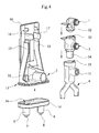
Es zeigt: - Figur 1:
- eine Darstellung eines Halters mit dem Zentralauslauf sowie zwei Koppeleinheiten in Explosivdarstellung,
- Figur 2:
- den Halter aus
Figur 1 in einer Ansicht von hinten mit montierten Koppeleinheiten, - Figur 3:
- einen Halter als Einzelteil und einen Zentralauslauf in Explosivdarstellung und
- Figur 4:
- eine Explosivdarstellung des Halters und eines zerlegten Zentralauslaufs.
- In den in der
Figur 1 dargestellten Halter 10 ist ein vollständig montierter Zentralauslauf 9 eingesetzt. Der Halter 10 besteht seinerseits aus einem Kunststoff und ist als einteiliges Bauteil gefertigt. In seinem unteren Abschnitt weist er einen Flansch 13 auf, auf den ein aus Silikon gefertigtes Verteilerelement 14 lösbar aufgesetzt ist. Innerhalb des Verteilerelementes 14 befinden sich Strömungskanäle, in denen gegebenenfalls eine Mischung der gewünschten Getränke erfolgt beziehungsweise über die eine Ausgabe der Getränke möglich ist, wobei hierzu Ausgabeleitungen 5 und 6 sowie Ausgabedüsen 7 und 8 vorhanden sind. Oberhalb des Flansches 13 geht der Halter 10 beidseitig in je einen Steg 15 über. Zwei beabstandet zueinander angeordnete Wangen 16,17 (siehe auchFigur 3 ) bilden ferner eine mechanische Kupplung, die unter elastischer Vorspannung den montierten Zentralauslauf 9 aufnimmt und am Halter 10 fixiert. Der Zentralauslauf 9 besteht bei dem gezeigten Ausführungsbeispiel seinerseits aus drei Einzelelementen. Im unteren Teil weist der Zentralauslauf 9 eine Fluidweiche 4 auf, die dazu dient ein Getränk beziehungsweise ein Getränkegemisch auf Ausgabeleitungen 5, 6 zu verteilen. Zwischen den Armen der Fluidweiche 4 befindet sich ein Fluidanschlussstück 2, dass über eine Aufnahmeöffnung 18 verfügt, in die ein korrespondierender Flansch 19 einer Koppeleinheit 20 einsetzbar ist. Die Koppeleinheit 20 dient hierbei der Zuführung von Kaffee. Folglich ist an der Koppeleinheit 20 eine Kaffeeleitung 21 vorhanden, über die der frisch gebrühte Kaffee zugeführt wird. Darüber hinaus weist die Koppeleinheit 20 in ihrem unteren Abschnitt einen Anschlag 22, eine Verdrehsicherung 23 sowie einen Haltering 24 zur Befestigung der Koppeleinheit 20 in dem Getränkebereiter auf. Etwa mittig des Zentralauslaufs 9 ist eine Kupplung 11 mit Magnet vorhanden. Der Magnet dient in Verbindung mit einem Reed-Kontakt zur Signalisierung der richtigen Montage des Halters 10 mit dem Zentralauslauf 9. Der Magnet kann zusätzlich eine Fixierungsfunktion ausüben. Die Kupplung 11 und die Fluidweiche 4 sind bei dem dargestellten Ausführungsbeispiel als ein einteiliges, aus Silikon erzeugtes Bauelement ausgeführt. Darüber hinaus weist der Zentralauslauf 9 ein Fluidanschlussstück 3 zur Zuführung von Milch sowie ein Fluidanschlussstück 1 zur Bereitstellung von Wasser und/oder Wasserdampf auf. Die Fluidanschlussstücke 1 und 3 sind jeweils als separierbare Einzelteile ausgeführt und können dichtend miteinander verbunden werden, wobei die strömungsleitenden Verbindungen jeweils durch einfache Steckverbindungen hergestellt werden. An dem Fluidanschlussstück 3 ist eine Muffe 25 und an dem Fluidanschlussstück 1 ebenfalls eine Muffe 26 vorhanden die einer strömungsleitenden und nach außen dichtenden Verbindung mit einer korrespondierenden Koppeleinheit 27 dient. Diese Koppeleinheit 27 verfügt über einen Anschluss 28 für Wasserdampf /Wasser, über einen Verbindungsflansch 29 für Wasserdampf /Wasser sowie über einen Verbindungsflansch 30 zur Zuführung der Milch. Die Verbindungsflansche 29, 30 werden in die korrespondierenden Muffen 26, 25 der Fluidanschlussstücke 1, 3 eingesetzt. - Aus der Darstellung in
Figur 2 geht eine Ansicht des Halters 10 von hinten hervor. Auf dieser Rückseite sind keine Bauelemente des Zentralauslaufs 9 angeordnet. Zur Erleichterung der Entnahme des gesamten Halters 10 aus dem Getränkebereiter beziehungsweise zur Vereinfachung des Einsetzens des Halters 10 weist dieser an seiner Rückseite einen Griff 12 auf. Der Griff 12 ist als einteiliges Element unmittelbar an den Halter 10 angeformt und folglich ebenfalls aus dem Grundmaterial Kunststoff des Halters 10 gefertigt. - Die
Figur 3 zeigt noch einmal einen Halter 10 und einen vom Halter 10 getrennten Zentralauslauf 9 in Explosivdarstellung. Der Zentralauslauf 9 besteht aus einem Fluidanschlussstück 1, einem mit diesem gekoppelten Fluidanschlussstück 3 sowie einer Fluidweiche 4, die als integralen Bestandteil eine Kupplung 11 aus einem Magneten aufweist. Die Fluidanschlussstücke 1, 3, beziehungsweise die Fluidweiche 4 sind über eine einfache Steckverbindung dichtend miteinander verbunden und können folglich zu Reinigungszwecken auseinandergenommen werden. An dem Halter 10 ist bei dieser Darstellung lediglich ein Anschlusszapfen 31 zu erkennen, von denen am Flansch 13 des Halters 10 jedoch zwei Stück vorhanden sind. Diese Anschlusszapfen 31 dienen der Herstellung einer Verbindung mit der Fluidweiche 4. - Die bereits angesprochene Möglichkeit, den Zentralauslauf 9 zu zerlegen, geht anschaulich aus der Darstellung in
Figur 4 hervor. So kann das Fluidanschlussstück 1 über einen kegelförmig ausgeführten Flansch 32 in eine korrespondierende Öffnung 33 des Fluidanschlussstückes 3 eingesetzt werden. Das Fluidanschlussstück 3 weist in seinem unteren Abschnitt ferner einen zylinderförmig ausgebildeten Flansch 34 auf, der passend und dichtend in die korrespondierende Öffnung 35 der Fluidweiche 4 einsetzbar ist, so dass insgesamt eine nach außen abgedichtete, jedoch strömungsleitende Verbindung innerhalb des gesamten Zentralauslaufs 9 hergestellt wird. Zu bemerken ist hinsichtlich derFigur 4 ferner, dass hieraus das vom Flansch 13 des Halters 10 entfernte Verteilerelement 14 als separates Bauteil erkennbar ist. Das Verteilerelement 14 verfügt in seinem Innenraum über Strömungskanäle 36, die der Zuführung des Getränkes oder eines Mischgetränkes beziehungsweise von Wasser/Wasserdampf zu den Ausgabeleitungen 5, 6 und somit zu den Ausgabedüsen 7, 8 dient. -
- 1
- Fluidanschlussstück
- 2
- Fluidanschlussstück
- 3
- Fluidanschlussstück
- 4
- Fluidweiche
- 5
- Ausgabeleitung
- 6
- Ausgabeleitung
- 7
- Ausgabedüse
- 8
- Ausgabedüse
- 9
- Zentralauslauf
- 10
- Halter
- 11
- Kupplung
- 12
- Griff
- 13
- Flansch
- 14
- Verteilerelement
- 15
- Steg
- 16
- Wange
- 17
- Wange
- 18
- Aufnahmeöffnung
- 19
- Flansch
- 20
- Koppeleinheit (Kaffee)
- 21
- Kaffeeleitung
- 22
- Anschlag
- 23
- Verdrehsicherung
- 24
- Haltering
- 25
- Muffe
- 26
- Muffe
- 27
- Koppeleinheit
- 28
- Anschluss Dampf/Wasser
- 29
- Verbindungsflansch
- 30
- Verbindungsflansch
- 31
- Anschlusszapfen
- 32
- Flansch
- 33
- Öffnung
- 34
- Flansch
- 35
- Öffnung
- 36
- Strömungskanäle
Claims (6)
- Zentralauslauf eines Getränkebereiters, der mehrere, mit einem Strömungsleitungssystem verbundene Fluidanschlussstücke (1, 2, 3) und eine Fluidweiche (4) mit mehreren Ausgabeleitungen (5, 6), die in je eine Ausgabedüse (7, 8) münden, aufweist,
dadurch gekennzeichnet, dass
die einzelnen Elemente des Zentralauslaufs (9) in einem gemeinsamen Halter (10) aufgenommen sind. - Zentralauslauf nach Anspruch 1,
dadurch gekennzeichnet, dass
zumindest die Fluidanschlussstücke (1, 2, 3) und die Fluidweiche (4) des Zentralauslaufs (9) lösbar in dem Halter (10) aufgenommen sind. - Zentralauslauf nach Anspruch 1 oder 2,
dadurch gekennzeichnet, dass
der Halter (10) insgesamt über eine Kupplung (11) lösbar in eine korrespondierende Aufnahme des Getränkebereiters eingesetzt ist. - Zentralauslauf nach Anspruch 3,
dadurch gekennzeichnet, dass
die Kupplung (11) einen Kraft- oder Formschluss mit der Aufnahme bildet oder eine Magnethalterung ist. - Zentralauslauf nach einem der vorstehend genannten Ansprüche,
dadurch gekennzeichnet, dass
der Halter (10) einen Griff (12) aufweist. - Zentralauslauf nach einem der vorstehend genannten Ansprüche,
dadurch gekennzeichnet, dass
der Zentralauslauf Bestandteil eines Kaffeeautomaten ist und ein Wasser beziehungsweise Wasserdampf führendes Fluidanschlussstück (1), ein Kaffee führendes Fluidanschlussstück (2) und ein Milch führendes Fluidanschlussstück (3) aufweist.
Priority Applications (3)
| Application Number | Priority Date | Filing Date | Title |
|---|---|---|---|
| ES11401641T ES2457522T3 (es) | 2011-11-24 | 2011-11-24 | Sistema de salida central de un preparador de bebidas |
| EP20110401641 EP2596728B1 (de) | 2011-11-24 | 2011-11-24 | Zentralauslauf eines Getränkebereiters |
| SI201130136T SI2596728T1 (sl) | 2011-11-24 | 2011-11-24 | Osrednji izpust pri napravah za pripravo napitka |
Applications Claiming Priority (1)
| Application Number | Priority Date | Filing Date | Title |
|---|---|---|---|
| EP20110401641 EP2596728B1 (de) | 2011-11-24 | 2011-11-24 | Zentralauslauf eines Getränkebereiters |
Publications (2)
| Publication Number | Publication Date |
|---|---|
| EP2596728A1 true EP2596728A1 (de) | 2013-05-29 |
| EP2596728B1 EP2596728B1 (de) | 2014-03-19 |
Family
ID=45218609
Family Applications (1)
| Application Number | Title | Priority Date | Filing Date |
|---|---|---|---|
| EP20110401641 Active EP2596728B1 (de) | 2011-11-24 | 2011-11-24 | Zentralauslauf eines Getränkebereiters |
Country Status (3)
| Country | Link |
|---|---|
| EP (1) | EP2596728B1 (de) |
| ES (1) | ES2457522T3 (de) |
| SI (1) | SI2596728T1 (de) |
Cited By (2)
| Publication number | Priority date | Publication date | Assignee | Title |
|---|---|---|---|---|
| EP2721976B1 (de) * | 2012-10-18 | 2014-09-17 | Miele & Cie. KG | Zerlegbarer Zentralauslauf eines Getränkebereiters |
| EP2732741B1 (de) * | 2012-11-16 | 2017-08-02 | Miele & Cie. KG | Getränkebereiter mit einem Zentralauslauf |
Citations (3)
| Publication number | Priority date | Publication date | Assignee | Title |
|---|---|---|---|---|
| EP0820715A1 (de) * | 1996-07-22 | 1998-01-28 | Wmf Württembergische Metallwarenfabrik Ag | Kaffeemaschine |
| EP2186454A1 (de) | 2008-11-07 | 2010-05-19 | BSH Bosch und Siemens Hausgeräte GmbH | Kaffeeautomat |
| EP2301396A1 (de) | 2009-09-29 | 2011-03-30 | Eugster/Frismag AG | Kaffee/Espressomaschine mit einer Milchschaumerzeugungseinrichtung für Cappuccino |
-
2011
- 2011-11-24 ES ES11401641T patent/ES2457522T3/es active Active
- 2011-11-24 SI SI201130136T patent/SI2596728T1/sl unknown
- 2011-11-24 EP EP20110401641 patent/EP2596728B1/de active Active
Patent Citations (3)
| Publication number | Priority date | Publication date | Assignee | Title |
|---|---|---|---|---|
| EP0820715A1 (de) * | 1996-07-22 | 1998-01-28 | Wmf Württembergische Metallwarenfabrik Ag | Kaffeemaschine |
| EP2186454A1 (de) | 2008-11-07 | 2010-05-19 | BSH Bosch und Siemens Hausgeräte GmbH | Kaffeeautomat |
| EP2301396A1 (de) | 2009-09-29 | 2011-03-30 | Eugster/Frismag AG | Kaffee/Espressomaschine mit einer Milchschaumerzeugungseinrichtung für Cappuccino |
Cited By (2)
| Publication number | Priority date | Publication date | Assignee | Title |
|---|---|---|---|---|
| EP2721976B1 (de) * | 2012-10-18 | 2014-09-17 | Miele & Cie. KG | Zerlegbarer Zentralauslauf eines Getränkebereiters |
| EP2732741B1 (de) * | 2012-11-16 | 2017-08-02 | Miele & Cie. KG | Getränkebereiter mit einem Zentralauslauf |
Also Published As
| Publication number | Publication date |
|---|---|
| SI2596728T1 (sl) | 2014-08-29 |
| EP2596728B1 (de) | 2014-03-19 |
| ES2457522T3 (es) | 2014-04-28 |
Similar Documents
| Publication | Publication Date | Title |
|---|---|---|
| EP2441360B1 (de) | Elektrische Getränkezubereitungsmaschine | |
| EP2854608B1 (de) | Ausgabeeinheit für einen getränkeautomaten, getränkeautomat mit einer solchen ausgabeeinheit sowie verfahren zum betrieb eines solchen getränkeautomaten | |
| DE3842206C2 (de) | Vorrichtung zum Zubereiten von Cappuccino | |
| EP2186454B1 (de) | Kaffeeautomat | |
| DE202011109479U1 (de) | Kaffee-/Espressomaschine mit einer Milchschaumerzeugungseinrichtung für Cappuccino | |
| EP2301396B1 (de) | Kaffee/Espressomaschine mit einer Milchschaumerzeugungseinrichtung für Cappuccino | |
| CH705198B1 (de) | Reinigungssystem für eine Kaffeemaschine. | |
| EP2589322A1 (de) | Kaffeemaschine, insbesondere Espressovollautomat | |
| DE202009007945U1 (de) | Vorrichtung, die zur Verwendung zum Schaumigschlagen von Milch geeignet ist | |
| DE202009001491U1 (de) | Vorrichtung zum Fördern von Milch | |
| EP3099208A1 (de) | Aromamodul sowie verfahren zum betrieb eines solchen aromamoduls | |
| EP2721976B1 (de) | Zerlegbarer Zentralauslauf eines Getränkebereiters | |
| EP2596728B1 (de) | Zentralauslauf eines Getränkebereiters | |
| DE102008014886B4 (de) | Milchaufschäumer | |
| DE102007060798B4 (de) | Vorrichtung zum Emulgieren einer Mischung aus Luft, Dampf und Milch | |
| EP2732741B1 (de) | Getränkebereiter mit einem Zentralauslauf | |
| DE102017115845B4 (de) | Milchschäumgerät | |
| EP2098146B1 (de) | Kaffeemaschine sowie Mehrwegeventil für eine Kaffeemaschine | |
| DE202014102435U1 (de) | Selbstbedienungs-Getränkeautomat | |
| EP1707090B1 (de) | Vorrichtung zur Erzeugung von Milchschaum und/oder zum Erhitzen von Milch | |
| DE202008015035U1 (de) | Vorrichtung zur Herstellung eines Brühgetränkes | |
| DE202014103175U1 (de) | Vorrichtung zum Aufschäumen einer Flüssigkeit | |
| DE102008014884A1 (de) | Getränkeautomat | |
| DE202008005730U1 (de) | Vorrichtung zur Erzeugung flüssiger Lebensmittel | |
| DE102023106900A1 (de) | Getränkezubereitungsvorrichtung, insbesondere Kaffeevollautomat, mit einem Membran-Schaummodul |
Legal Events
| Date | Code | Title | Description |
|---|---|---|---|
| PUAI | Public reference made under article 153(3) epc to a published international application that has entered the european phase |
Free format text: ORIGINAL CODE: 0009012 |
|
| 17P | Request for examination filed |
Effective date: 20120622 |
|
| AK | Designated contracting states |
Kind code of ref document: A1 Designated state(s): AL AT BE BG CH CY CZ DE DK EE ES FI FR GB GR HR HU IE IS IT LI LT LU LV MC MK MT NL NO PL PT RO RS SE SI SK SM TR |
|
| AX | Request for extension of the european patent |
Extension state: BA ME |
|
| RIC1 | Information provided on ipc code assigned before grant |
Ipc: A47J 31/46 20060101AFI20130829BHEP |
|
| GRAP | Despatch of communication of intention to grant a patent |
Free format text: ORIGINAL CODE: EPIDOSNIGR1 |
|
| INTG | Intention to grant announced |
Effective date: 20131025 |
|
| GRAS | Grant fee paid |
Free format text: ORIGINAL CODE: EPIDOSNIGR3 |
|
| GRAA | (expected) grant |
Free format text: ORIGINAL CODE: 0009210 |
|
| AK | Designated contracting states |
Kind code of ref document: B1 Designated state(s): AL AT BE BG CH CY CZ DE DK EE ES FI FR GB GR HR HU IE IS IT LI LT LU LV MC MK MT NL NO PL PT RO RS SE SI SK SM TR |
|
| REG | Reference to a national code |
Ref country code: GB Ref legal event code: FG4D Free format text: NOT ENGLISH |
|
| REG | Reference to a national code |
Ref country code: CH Ref legal event code: EP |
|
| REG | Reference to a national code |
Ref country code: AT Ref legal event code: REF Ref document number: 657088 Country of ref document: AT Kind code of ref document: T Effective date: 20140415 Ref country code: CH Ref legal event code: NV Representative=s name: FIAMMENGHI-FIAMMENGHI, CH |
|
| REG | Reference to a national code |
Ref country code: IE Ref legal event code: FG4D Free format text: LANGUAGE OF EP DOCUMENT: GERMAN |
|
| REG | Reference to a national code |
Ref country code: ES Ref legal event code: GC2A Effective date: 20140416 |
|
| REG | Reference to a national code |
Ref country code: ES Ref legal event code: FG2A Ref document number: 2457522 Country of ref document: ES Kind code of ref document: T3 Effective date: 20140428 |
|
| REG | Reference to a national code |
Ref country code: DE Ref legal event code: R096 Ref document number: 502011002428 Country of ref document: DE Effective date: 20140430 Ref country code: GB Ref legal event code: 746 Effective date: 20140408 |
|
| REG | Reference to a national code |
Ref country code: DE Ref legal event code: R084 Ref document number: 502011002428 Country of ref document: DE Effective date: 20140328 |
|
| PG25 | Lapsed in a contracting state [announced via postgrant information from national office to epo] |
Ref country code: LT Free format text: LAPSE BECAUSE OF FAILURE TO SUBMIT A TRANSLATION OF THE DESCRIPTION OR TO PAY THE FEE WITHIN THE PRESCRIBED TIME-LIMIT Effective date: 20140319 Ref country code: NO Free format text: LAPSE BECAUSE OF FAILURE TO SUBMIT A TRANSLATION OF THE DESCRIPTION OR TO PAY THE FEE WITHIN THE PRESCRIBED TIME-LIMIT Effective date: 20140619 |
|
| REG | Reference to a national code |
Ref country code: NL Ref legal event code: VDEP Effective date: 20140319 |
|
| REG | Reference to a national code |
Ref country code: LT Ref legal event code: MG4D |
|
| PG25 | Lapsed in a contracting state [announced via postgrant information from national office to epo] |
Ref country code: CY Free format text: LAPSE BECAUSE OF FAILURE TO SUBMIT A TRANSLATION OF THE DESCRIPTION OR TO PAY THE FEE WITHIN THE PRESCRIBED TIME-LIMIT Effective date: 20140319 Ref country code: SE Free format text: LAPSE BECAUSE OF FAILURE TO SUBMIT A TRANSLATION OF THE DESCRIPTION OR TO PAY THE FEE WITHIN THE PRESCRIBED TIME-LIMIT Effective date: 20140319 Ref country code: FI Free format text: LAPSE BECAUSE OF FAILURE TO SUBMIT A TRANSLATION OF THE DESCRIPTION OR TO PAY THE FEE WITHIN THE PRESCRIBED TIME-LIMIT Effective date: 20140319 |
|
| PG25 | Lapsed in a contracting state [announced via postgrant information from national office to epo] |
Ref country code: HR Free format text: LAPSE BECAUSE OF FAILURE TO SUBMIT A TRANSLATION OF THE DESCRIPTION OR TO PAY THE FEE WITHIN THE PRESCRIBED TIME-LIMIT Effective date: 20140319 Ref country code: RS Free format text: LAPSE BECAUSE OF FAILURE TO SUBMIT A TRANSLATION OF THE DESCRIPTION OR TO PAY THE FEE WITHIN THE PRESCRIBED TIME-LIMIT Effective date: 20140319 Ref country code: LV Free format text: LAPSE BECAUSE OF FAILURE TO SUBMIT A TRANSLATION OF THE DESCRIPTION OR TO PAY THE FEE WITHIN THE PRESCRIBED TIME-LIMIT Effective date: 20140319 |
|
| PG25 | Lapsed in a contracting state [announced via postgrant information from national office to epo] |
Ref country code: CZ Free format text: LAPSE BECAUSE OF FAILURE TO SUBMIT A TRANSLATION OF THE DESCRIPTION OR TO PAY THE FEE WITHIN THE PRESCRIBED TIME-LIMIT Effective date: 20140319 Ref country code: NL Free format text: LAPSE BECAUSE OF FAILURE TO SUBMIT A TRANSLATION OF THE DESCRIPTION OR TO PAY THE FEE WITHIN THE PRESCRIBED TIME-LIMIT Effective date: 20140319 Ref country code: BG Free format text: LAPSE BECAUSE OF FAILURE TO SUBMIT A TRANSLATION OF THE DESCRIPTION OR TO PAY THE FEE WITHIN THE PRESCRIBED TIME-LIMIT Effective date: 20140619 Ref country code: EE Free format text: LAPSE BECAUSE OF FAILURE TO SUBMIT A TRANSLATION OF THE DESCRIPTION OR TO PAY THE FEE WITHIN THE PRESCRIBED TIME-LIMIT Effective date: 20140319 Ref country code: RO Free format text: LAPSE BECAUSE OF FAILURE TO SUBMIT A TRANSLATION OF THE DESCRIPTION OR TO PAY THE FEE WITHIN THE PRESCRIBED TIME-LIMIT Effective date: 20140319 Ref country code: IS Free format text: LAPSE BECAUSE OF FAILURE TO SUBMIT A TRANSLATION OF THE DESCRIPTION OR TO PAY THE FEE WITHIN THE PRESCRIBED TIME-LIMIT Effective date: 20140719 |
|
| PG25 | Lapsed in a contracting state [announced via postgrant information from national office to epo] |
Ref country code: PL Free format text: LAPSE BECAUSE OF FAILURE TO SUBMIT A TRANSLATION OF THE DESCRIPTION OR TO PAY THE FEE WITHIN THE PRESCRIBED TIME-LIMIT Effective date: 20140319 Ref country code: SK Free format text: LAPSE BECAUSE OF FAILURE TO SUBMIT A TRANSLATION OF THE DESCRIPTION OR TO PAY THE FEE WITHIN THE PRESCRIBED TIME-LIMIT Effective date: 20140319 |
|
| REG | Reference to a national code |
Ref country code: DE Ref legal event code: R097 Ref document number: 502011002428 Country of ref document: DE |
|
| PG25 | Lapsed in a contracting state [announced via postgrant information from national office to epo] |
Ref country code: PT Free format text: LAPSE BECAUSE OF FAILURE TO SUBMIT A TRANSLATION OF THE DESCRIPTION OR TO PAY THE FEE WITHIN THE PRESCRIBED TIME-LIMIT Effective date: 20140721 |
|
| PLBE | No opposition filed within time limit |
Free format text: ORIGINAL CODE: 0009261 |
|
| STAA | Information on the status of an ep patent application or granted ep patent |
Free format text: STATUS: NO OPPOSITION FILED WITHIN TIME LIMIT |
|
| PG25 | Lapsed in a contracting state [announced via postgrant information from national office to epo] |
Ref country code: DK Free format text: LAPSE BECAUSE OF FAILURE TO SUBMIT A TRANSLATION OF THE DESCRIPTION OR TO PAY THE FEE WITHIN THE PRESCRIBED TIME-LIMIT Effective date: 20140319 |
|
| 26N | No opposition filed |
Effective date: 20141222 |
|
| REG | Reference to a national code |
Ref country code: DE Ref legal event code: R097 Ref document number: 502011002428 Country of ref document: DE Effective date: 20141222 |
|
| PG25 | Lapsed in a contracting state [announced via postgrant information from national office to epo] |
Ref country code: MC Free format text: LAPSE BECAUSE OF FAILURE TO SUBMIT A TRANSLATION OF THE DESCRIPTION OR TO PAY THE FEE WITHIN THE PRESCRIBED TIME-LIMIT Effective date: 20140319 Ref country code: LU Free format text: LAPSE BECAUSE OF FAILURE TO SUBMIT A TRANSLATION OF THE DESCRIPTION OR TO PAY THE FEE WITHIN THE PRESCRIBED TIME-LIMIT Effective date: 20141124 Ref country code: BE Free format text: LAPSE BECAUSE OF NON-PAYMENT OF DUE FEES Effective date: 20141130 |
|
| REG | Reference to a national code |
Ref country code: IE Ref legal event code: MM4A |
|
| PG25 | Lapsed in a contracting state [announced via postgrant information from national office to epo] |
Ref country code: IE Free format text: LAPSE BECAUSE OF NON-PAYMENT OF DUE FEES Effective date: 20141124 |
|
| REG | Reference to a national code |
Ref country code: FR Ref legal event code: PLFP Year of fee payment: 5 |
|
| PG25 | Lapsed in a contracting state [announced via postgrant information from national office to epo] |
Ref country code: SM Free format text: LAPSE BECAUSE OF FAILURE TO SUBMIT A TRANSLATION OF THE DESCRIPTION OR TO PAY THE FEE WITHIN THE PRESCRIBED TIME-LIMIT Effective date: 20140319 |
|
| PG25 | Lapsed in a contracting state [announced via postgrant information from national office to epo] |
Ref country code: GR Free format text: LAPSE BECAUSE OF FAILURE TO SUBMIT A TRANSLATION OF THE DESCRIPTION OR TO PAY THE FEE WITHIN THE PRESCRIBED TIME-LIMIT Effective date: 20140620 |
|
| PG25 | Lapsed in a contracting state [announced via postgrant information from national office to epo] |
Ref country code: MT Free format text: LAPSE BECAUSE OF FAILURE TO SUBMIT A TRANSLATION OF THE DESCRIPTION OR TO PAY THE FEE WITHIN THE PRESCRIBED TIME-LIMIT Effective date: 20140319 Ref country code: TR Free format text: LAPSE BECAUSE OF FAILURE TO SUBMIT A TRANSLATION OF THE DESCRIPTION OR TO PAY THE FEE WITHIN THE PRESCRIBED TIME-LIMIT Effective date: 20140319 Ref country code: HU Free format text: LAPSE BECAUSE OF FAILURE TO SUBMIT A TRANSLATION OF THE DESCRIPTION OR TO PAY THE FEE WITHIN THE PRESCRIBED TIME-LIMIT; INVALID AB INITIO Effective date: 20111124 |
|
| REG | Reference to a national code |
Ref country code: FR Ref legal event code: PLFP Year of fee payment: 6 |
|
| REG | Reference to a national code |
Ref country code: FR Ref legal event code: PLFP Year of fee payment: 7 |
|
| REG | Reference to a national code |
Ref country code: AT Ref legal event code: MM01 Ref document number: 657088 Country of ref document: AT Kind code of ref document: T Effective date: 20161124 |
|
| PG25 | Lapsed in a contracting state [announced via postgrant information from national office to epo] |
Ref country code: AT Free format text: LAPSE BECAUSE OF NON-PAYMENT OF DUE FEES Effective date: 20161124 |
|
| PG25 | Lapsed in a contracting state [announced via postgrant information from national office to epo] |
Ref country code: MK Free format text: LAPSE BECAUSE OF FAILURE TO SUBMIT A TRANSLATION OF THE DESCRIPTION OR TO PAY THE FEE WITHIN THE PRESCRIBED TIME-LIMIT Effective date: 20140319 |
|
| PG25 | Lapsed in a contracting state [announced via postgrant information from national office to epo] |
Ref country code: AL Free format text: LAPSE BECAUSE OF FAILURE TO SUBMIT A TRANSLATION OF THE DESCRIPTION OR TO PAY THE FEE WITHIN THE PRESCRIBED TIME-LIMIT Effective date: 20140319 |
|
| PGFP | Annual fee paid to national office [announced via postgrant information from national office to epo] |
Ref country code: IT Payment date: 20221122 Year of fee payment: 12 Ref country code: FR Payment date: 20221122 Year of fee payment: 12 Ref country code: ES Payment date: 20221213 Year of fee payment: 12 |
|
| PGFP | Annual fee paid to national office [announced via postgrant information from national office to epo] |
Ref country code: SI Payment date: 20221110 Year of fee payment: 12 |
|
| P01 | Opt-out of the competence of the unified patent court (upc) registered |
Effective date: 20230529 |
|
| PGFP | Annual fee paid to national office [announced via postgrant information from national office to epo] |
Ref country code: GB Payment date: 20231121 Year of fee payment: 13 |
|
| PGFP | Annual fee paid to national office [announced via postgrant information from national office to epo] |
Ref country code: CH Payment date: 20231201 Year of fee payment: 13 |
|
| PG25 | Lapsed in a contracting state [announced via postgrant information from national office to epo] |
Ref country code: SI Free format text: LAPSE BECAUSE OF NON-PAYMENT OF DUE FEES Effective date: 20231125 |
|
| REG | Reference to a national code |
Ref country code: SI Ref legal event code: KO00 Effective date: 20240813 |
|
| PG25 | Lapsed in a contracting state [announced via postgrant information from national office to epo] |
Ref country code: FR Free format text: LAPSE BECAUSE OF NON-PAYMENT OF DUE FEES Effective date: 20231130 |
|
| PG25 | Lapsed in a contracting state [announced via postgrant information from national office to epo] |
Ref country code: FR Free format text: LAPSE BECAUSE OF NON-PAYMENT OF DUE FEES Effective date: 20231130 |
|
| PG25 | Lapsed in a contracting state [announced via postgrant information from national office to epo] |
Ref country code: IT Free format text: LAPSE BECAUSE OF NON-PAYMENT OF DUE FEES Effective date: 20231124 |
|
| PG25 | Lapsed in a contracting state [announced via postgrant information from national office to epo] |
Ref country code: IT Free format text: LAPSE BECAUSE OF NON-PAYMENT OF DUE FEES Effective date: 20231124 |
|
| REG | Reference to a national code |
Ref country code: ES Ref legal event code: FD2A Effective date: 20250107 |
|
| PG25 | Lapsed in a contracting state [announced via postgrant information from national office to epo] |
Ref country code: ES Free format text: LAPSE BECAUSE OF NON-PAYMENT OF DUE FEES Effective date: 20231125 |
|
| PG25 | Lapsed in a contracting state [announced via postgrant information from national office to epo] |
Ref country code: ES Free format text: LAPSE BECAUSE OF NON-PAYMENT OF DUE FEES Effective date: 20231125 |
|
| REG | Reference to a national code |
Ref country code: CH Ref legal event code: PL |
|
| REG | Reference to a national code |
Ref country code: CH Ref legal event code: PL |
|
| GBPC | Gb: european patent ceased through non-payment of renewal fee |
Effective date: 20241124 |
|
| PG25 | Lapsed in a contracting state [announced via postgrant information from national office to epo] |
Ref country code: CH Free format text: LAPSE BECAUSE OF NON-PAYMENT OF DUE FEES Effective date: 20241130 |
|
| PG25 | Lapsed in a contracting state [announced via postgrant information from national office to epo] |
Ref country code: GB Free format text: LAPSE BECAUSE OF NON-PAYMENT OF DUE FEES Effective date: 20241124 |
|
| PGFP | Annual fee paid to national office [announced via postgrant information from national office to epo] |
Ref country code: DE Payment date: 20251130 Year of fee payment: 15 |