EP2596603B1 - Ethernet-schalter und verfahren zum routen von ethernet-datenpaketen - Google Patents
Ethernet-schalter und verfahren zum routen von ethernet-datenpaketen Download PDFInfo
- Publication number
- EP2596603B1 EP2596603B1 EP11745568.3A EP11745568A EP2596603B1 EP 2596603 B1 EP2596603 B1 EP 2596603B1 EP 11745568 A EP11745568 A EP 11745568A EP 2596603 B1 EP2596603 B1 EP 2596603B1
- Authority
- EP
- European Patent Office
- Prior art keywords
- data packet
- lag
- link aggregation
- aggregation group
- information
- Prior art date
- Legal status (The legal status is an assumption and is not a legal conclusion. Google has not performed a legal analysis and makes no representation as to the accuracy of the status listed.)
- Active
Links
- 238000000034 method Methods 0.000 title claims description 23
- 230000002776 aggregation Effects 0.000 claims description 25
- 238000004220 aggregation Methods 0.000 claims description 25
- 239000004744 fabric Substances 0.000 claims description 13
- 238000013519 translation Methods 0.000 description 12
- 230000007246 mechanism Effects 0.000 description 8
- 230000003044 adaptive effect Effects 0.000 description 7
- 238000000786 liquid-assisted grinding Methods 0.000 description 6
- 238000004891 communication Methods 0.000 description 5
- 238000006424 Flood reaction Methods 0.000 description 3
- 238000012545 processing Methods 0.000 description 3
- 230000008859 change Effects 0.000 description 2
- 238000005538 encapsulation Methods 0.000 description 2
- 238000001914 filtration Methods 0.000 description 2
- RYGMFSIKBFXOCR-UHFFFAOYSA-N Copper Chemical compound [Cu] RYGMFSIKBFXOCR-UHFFFAOYSA-N 0.000 description 1
- 235000008694 Humulus lupulus Nutrition 0.000 description 1
- 230000005540 biological transmission Effects 0.000 description 1
- 230000003139 buffering effect Effects 0.000 description 1
- 229910052802 copper Inorganic materials 0.000 description 1
- 239000010949 copper Substances 0.000 description 1
- 125000004122 cyclic group Chemical group 0.000 description 1
- 230000000694 effects Effects 0.000 description 1
- 230000006855 networking Effects 0.000 description 1
- 230000008569 process Effects 0.000 description 1
- 238000012360 testing method Methods 0.000 description 1
- 230000007704 transition Effects 0.000 description 1
Images


Classifications
-
- H—ELECTRICITY
- H04—ELECTRIC COMMUNICATION TECHNIQUE
- H04L—TRANSMISSION OF DIGITAL INFORMATION, e.g. TELEGRAPHIC COMMUNICATION
- H04L45/00—Routing or path finding of packets in data switching networks
- H04L45/74—Address processing for routing
-
- H—ELECTRICITY
- H04—ELECTRIC COMMUNICATION TECHNIQUE
- H04L—TRANSMISSION OF DIGITAL INFORMATION, e.g. TELEGRAPHIC COMMUNICATION
- H04L49/00—Packet switching elements
- H04L49/35—Switches specially adapted for specific applications
- H04L49/351—Switches specially adapted for specific applications for local area network [LAN], e.g. Ethernet switches
-
- H—ELECTRICITY
- H04—ELECTRIC COMMUNICATION TECHNIQUE
- H04L—TRANSMISSION OF DIGITAL INFORMATION, e.g. TELEGRAPHIC COMMUNICATION
- H04L12/00—Data switching networks
- H04L12/28—Data switching networks characterised by path configuration, e.g. LAN [Local Area Networks] or WAN [Wide Area Networks]
- H04L12/46—Interconnection of networks
- H04L12/4604—LAN interconnection over a backbone network, e.g. Internet, Frame Relay
- H04L12/462—LAN interconnection over a bridge based backbone
- H04L12/4625—Single bridge functionality, e.g. connection of two networks over a single bridge
-
- H—ELECTRICITY
- H04—ELECTRIC COMMUNICATION TECHNIQUE
- H04L—TRANSMISSION OF DIGITAL INFORMATION, e.g. TELEGRAPHIC COMMUNICATION
- H04L12/00—Data switching networks
- H04L12/28—Data switching networks characterised by path configuration, e.g. LAN [Local Area Networks] or WAN [Wide Area Networks]
- H04L12/46—Interconnection of networks
- H04L12/4633—Interconnection of networks using encapsulation techniques, e.g. tunneling
-
- H—ELECTRICITY
- H04—ELECTRIC COMMUNICATION TECHNIQUE
- H04L—TRANSMISSION OF DIGITAL INFORMATION, e.g. TELEGRAPHIC COMMUNICATION
- H04L45/00—Routing or path finding of packets in data switching networks
- H04L45/24—Multipath
- H04L45/245—Link aggregation, e.g. trunking
-
- H—ELECTRICITY
- H04—ELECTRIC COMMUNICATION TECHNIQUE
- H04L—TRANSMISSION OF DIGITAL INFORMATION, e.g. TELEGRAPHIC COMMUNICATION
- H04L45/00—Routing or path finding of packets in data switching networks
- H04L45/66—Layer 2 routing, e.g. in Ethernet based MAN's
-
- H—ELECTRICITY
- H04—ELECTRIC COMMUNICATION TECHNIQUE
- H04L—TRANSMISSION OF DIGITAL INFORMATION, e.g. TELEGRAPHIC COMMUNICATION
- H04L49/00—Packet switching elements
- H04L49/25—Routing or path finding in a switch fabric
-
- Y—GENERAL TAGGING OF NEW TECHNOLOGICAL DEVELOPMENTS; GENERAL TAGGING OF CROSS-SECTIONAL TECHNOLOGIES SPANNING OVER SEVERAL SECTIONS OF THE IPC; TECHNICAL SUBJECTS COVERED BY FORMER USPC CROSS-REFERENCE ART COLLECTIONS [XRACs] AND DIGESTS
- Y02—TECHNOLOGIES OR APPLICATIONS FOR MITIGATION OR ADAPTATION AGAINST CLIMATE CHANGE
- Y02D—CLIMATE CHANGE MITIGATION TECHNOLOGIES IN INFORMATION AND COMMUNICATION TECHNOLOGIES [ICT], I.E. INFORMATION AND COMMUNICATION TECHNOLOGIES AIMING AT THE REDUCTION OF THEIR OWN ENERGY USE
- Y02D30/00—Reducing energy consumption in communication networks
- Y02D30/50—Reducing energy consumption in communication networks in wire-line communication networks, e.g. low power modes or reduced link rate
Definitions
- the present invention relates to data switching networks, and, in particular, to link aggregation groups in Ethernet switching networks.
- Ethernet is a frame-based networking technique primarily used for local area networks (LANs).
- a typical Ethernet switching network includes one or more Ethernet bridges that house switching elements for routing data between a plurality of data ingress ports and a plurality of data egress ports.
- a Link Aggregation Group is a collection of physical network links brought together to provide a single logical channel of higher bandwidth.
- the Link Aggregation Control Protocol (LACP) is part of the IEEE specification 802.3ad.
- Figure 1 of the accompanying drawings shows a typical Ethernet LAG.
- First and second Ethernet bridges 2 and 4 are connected by Ethernet links 10.
- the first bridge 2 has a plurality of data ingress/egress ports 6, and the second bridge 4 has a plurality of data ingress/egress ports 8.
- the LAG has four links 10 connecting the two Ethernet bridges 2 and 4 providing up to 4 times the bandwidth of a single link.
- LACP allows a network device connected to an ingress/egress port of a bridge to negotiate an automatic bundling of links by sending LACP management frames to the peer.
- LACP works by sending frames (LACPDUs) down all links that have the protocol enabled. If a device is present on the other end of the link that also has LACP enabled, it will also independently send frames along the same links enabling the two units to detect multiple links between themselves and then combine them into a single logical link.
- LACP can be configured in one of two modes: Active or Passive. In Active mode it will always send frames along the configured links. In passive mode however, it acts as "speak when spoken to", and therefore can be used as a way of controlling accidental loops (as long as the other device is in active mode).
- Link aggregation presents a number of problems for Ethernet-based communications.
- Ethernet networks use a defined protocol to determine the spanning tree of the network and disable any links that offer alternate paths to a destination. This ensures there is only one route from a source to a destination. Additionally, there is only one source to destination connection for network traffic that uses an Ethernet LAG. This means that a particular source to destination connection will always use the same link within the LAG.
- a LAG uses a distribution algorithm based upon source and/or destination network addresses of the connected devices to define the connections to be made on the individual Ethernet links that form the LAG. Typically a number of different distribution algorithms are available to a network administrator. The network administrator will choose the algorithm that gives the most even distribution of network traffic across the LAG depending upon a number of pre-determined, site specific parameters.
- the distribution algorithm is normally based on either the source or destination MAC addresses or a combination of both the source and the destination MAC addresses to select an Ethernet link within the LAG for the Ethernet frame to be delivered on.
- Other distribution algorithms may use the IP address and port numbers of the layer 3 protocol. Having a single route or path for the packets to follow does simplify a number of issues. Ethernet packets should be delivered in order. Having a single route from source to destination guarantees that one packet cannot overtake another. This greatly improves the performance of higher-level protocols. Ethernet is normally the data link layer for TCP/IP and UDP/IP. TCP can receive IP packets in a different order from the order they were sent but this requires a significant processing and buffering overhead at the receiving node.
- the simplification of a single route also means that the packet load, over the LAG, can be very unbalanced.
- Full utilization of the LAG requires all links to be transmitting data. This in turn requires a number of communications to occur concurrently with routes that send the data along different links of the LAG. The probability of better utilization increases with the number of different conversations being relayed across the LAG. The greater the number of links in the LAG then the greater the number of conversations are needed to keep all the links of the LAG active.
- a distribution algorithm is required to implement a LAG. This will select the link that is used to relay a packet across the LAG. This has to be executed at the same time that the MAC tables are accessed to perform the MAC address to destination port translation. This usually restricts the width of the LAG to a proportion (no more than half) of the links on the Ethernet switch chip. The physical implementation of an Ethernet switch usually puts an upper limit on this number.
- Figure 2 of the accompanying drawings gives an example of a multi-switch LAG. Having first and second Ethernet bridges 12 and 14, each of which has two layers of internal switching, provided by respective pluralities of switches 16 and 18, interconnected by internal links 20 and 22 respectively.
- Each bridge 12, 14 has a plurality of ingress/egress ports 24, 26 through which data passes for routing by the switches 16 and 18.
- the bridges 12, 14 are connected to one another by a plurality of Ethernet links 28 over which data is passed. These Ethernet links are arranged into a LAG 30, in order to provide an effective increase in bandwidth between the bridges 12 and 14.
- the example shows each Ethernet bridge having two layers of switching.
- the method works equally well with many more layers of switching and also with switch chips with many more ports per switch than the 8 shown per switch in the Figure.
- the internal topology used in Figure 2 is also an example and the method works equally well with other topologies.
- FIG. 3 of the accompanying drawings gives an example of a multi-switch LAG which is similar to the example shown in Figure 2 .
- some of the links 34 within the range of LAG 30 are assigned as normal Ethernet bridge links outside of the LAG 30.
- Ethernet LAGs are typically limited to a small number of Ethernet Links, perhaps 4 or 8. At the time of writing the maximum available 10GbE links in a LAG was 16.
- Ethernet switches for routing Ethernet data packets are also disclosed in the patent publications: US2006/251074 , US2007/098006 and US2007/268915 .
- an Ethernet switch for routing Ethernet data packets, the switch comprising a data ingress port, a plurality of data egress ports, network fabric connecting the data ingress port with the data egress ports, and comprising a plurality of interconnected switching elements, an encapsulator connected for reception of an incoming data packet from the ingress port, and operable to generate an internal data packet comprising a header portion and a payload portion, the header portion including routing information relating to a route through the interconnected switching elements, and derived from routing information of an incoming data packet, and the payload portion comprising that incoming data packet, wherein the encapsulator is also operable to determine whether the routing information of the incoming data packet relates to a LAG having multiple links associated therewith, and, if so, to generate LAG information for inclusion in the header of the internal data packet, and wherein the LAG information includes a distribution value for use in determining selection of one of the links associated with the LAG for routing of the data packet concerned.
- a method of routing Ethernet data packets in an Ethernet switch having a data ingress port, a plurality of data egress ports, and network fabric connecting the data ingress port with the data egress ports, and comprising a plurality of interconnected switching elements
- the method comprising the steps of receiving an incoming data packet, generating an internal data packet which includes a header portion and a payload portion, the header portion including routing information relating to a route through the interconnected switching elements, and derived from routing information of an incoming data packet, and the payload portion comprising that incoming data packet, determining whether the routing information of the incoming data packet relates to a LAG having multiple egress ports associated therewith, and, if so, generating LAG information for inclusion in the header of the internal data packet, wherein the LAG information includes a distribution value for use in determining selection of one of the egress ports associated with the LAG for routing of the data packet concerned, routing the internal data packet through the network fabric using the routing information,
- Such a technique enables LAG to be managed across a large network fabric.
- LAG information is generated only once, upon entry to the switch, for a particular incoming data packet. This reduces the amount of processing time required to route the internal data packet through the switch fabric.
- the encapsulator is operable to determine a LAG algorithm from the routing information of an incoming data packet, and to use such a determined LAG algorithm to generate the distribution value for the data packet concerned. This allows different distribution algorithms to be used for different packets, and so the most appropriate distribution of data packets to a LAG for the data packet type concerned can be utilised.
- Each switching element of the network fabric may include storage means operable to store output information indicative of an output route from the switching element concerned, the switching element being operable to access stored output information in dependence upon received LAG information.
- the encapsulator may then be operable to determine a LAG width value from the routing information of the incoming data packet, the width value being indicative of an amount of LAG information to be used for accessing stored output information.
- Each switching element may also include weighted distribution logic operable to produce an output port selection signal in dependence upon retrieved output information.
- each switching element includes a data packet filter which is operable to discard data packets in dependence upon the distribution value associated therewith.
- Embodiments of the invention serve to provide techniques that allow Ethernet links to be aggregated to any width.
- an Ethernet switch for routing Ethernet data packets, the switch comprising a data ingress port, a plurality of data egress ports having respective output links, and network fabric connecting the data ingress port with the data egress ports, and comprising a plurality of interconnected switching elements, the ingress port being connected to each of the output ports via a plurality of switching elements, wherein each of a plurality of the switching elements includes a packet processor connected for reception of an incoming data packet, and operable to determine whether routing information contained in the incoming data packet relates to a LAG having multiple output links associated therewith, and, if so, to route the data packet towards one of the output links associated with the LAG.
- Each switching element may include a packet processor connected for reception of an incoming data packet, and operable to determine whether routing information contained in the incoming data packet relates to a LAG having multiple output links associated therewith, and, if so, to route the data packet towards one of the output links associated with the LAG.
- a packet processor connected for reception of an incoming data packet, and operable to determine whether routing information contained in the incoming data packet relates to a LAG having multiple output links associated therewith, and, if so, to route the data packet towards one of the output links associated with the LAG.
- a method of routing Ethernet data packets in an Ethernet switch having a data ingress port, a plurality of data egress ports having respective output links, and network fabric connecting the data ingress port with the data egress ports, and comprising a plurality of interconnected switching elements, the ingress port being connected to each of the output ports via a plurality of switching elements, the method comprising the steps of, in each of a plurality of the switching elements, receiving an incoming data packet, determining whether routing information contained in the incoming data packet relates to a LAG having multiple egress ports associated therewith, and, if so, routing the incoming data packet to one of the output links associated with the LAG.
- Such a method may include the steps of, at each switching element receiving an incoming data packet, determining whether routing information contained in the incoming data packet relates to a LAG having multiple egress ports associated therewith, and, if so, routing the incoming data packet towards one of the output links associated with the LAG.
- Embodiments of such aspects of the present invention can thereby apply the techniques of the first and second aspects to unencapsulated data packets.
- FIG. 4 of the accompanying drawings illustrates an example of a "Fat Tree” network, sometimes referred to as a "Clos" network.
- a Fat Tree network is suitable for use as the internal network of the Ethernet bridges 12 and 14 of Figures 2 and 3 .
- the Fat Tree network of Figure 4 will be used to describe the operation of a wide LAG mechanism embodying the present invention. However, any network topology could be used to implement such mechanism and the Fat Tree is only used in this context as a convenient example.
- the internal network of Figure 4 comprises a plurality of switching elements 40 which are interconnected by a plurality of links 41.
- the switching elements are arranged in three hierarchical levels 43, 44 and 45.
- Switching elements in the first level 43 provide data ingress and egress ports 42 for the internal network.
- the switching elements 40 in the first and second levels 43 and 44 are divided into three groups, and within each group, each of the switching elements 40 in the first level 43 are connected with each of the elements 40 in the second level 44.
- the switching elements 40 in the third level 45 are each connected with one switching element from each of the three groups in the second level 44.
- Such a topology maintains total cross sectional bandwidth and provides multiple routes from each ingress port to each egress port 42.
- a Fat Tree communication is performed by moving up the tree from one of the ingress ports 42 to a point high enough in the internal network to give visibility of a required egress port. If the communication was for a neighbouring port on a switching element, the connection could be made without using any additional switching elements. For slightly more distant ports the packet could be routed up one level of the network before turning back down to visit the switching element with the final egress port 42. In this case the packet would traverse 3 switching elements 40. For distant ports the internal data packets may have to pass up through a number of switching elements 40 before turning back down the network towards the required egress port 42.
- Fat Tree networks have the property of only needing an absolute route path on the way down the network. Any upward route can be used and the same downward route will end up at the correct egress port. This can be useful in networks employing adaptive routing as the adaptive choice can be very general and does not need to be specific to particular egress ports.
- An adaptive route can respond to the current network load and can direct traffic away from congested links.
- Ethernet LAGs must also correctly support floods, broadcasts and multicast operations.
- Ethernet flood is the mechanism used to route packets to the correct destination when the route to the destination has not yet been learned by the MAC address translation tables.
- a broadcast has a special MAC address value that indicates the packet should be sent to all destinations.
- a broadcast will also direct the packet to all bridge egress ports except the one associated with the ingress port the packet arrived on. Multicast packets are sent to a subset of all the egress ports (again excluding the ingress port).
- a LAG is a single logical link and so only one packet should appear on one of the links within the LAG for floods, broadcasts and multicasts. For a flood the packet should appear on the same link it would have appeared on if the packet had not been flooded. This is required to guarantee the order of a packet stream as the first packet may be flooded but the second packet may become a normal unicast packet if the destination becomes learned between the two packets.
- Each switching element 40 that provides an ingress port 42 for the internal network includes an encapsulator.
- the encapsulator is operable to encapsulate incoming Ethernet frames into an internal data packet when they are received at the ingress port.
- Each internal data packet has a header, a body that contains an unaltered Ethernet frame and a checksum value to test the integrity of the Ethernet frame data.
- the destination MAC address of the incoming Ethernet frame is translated, and it is determined whether a network wide-Ethernet LAG egress port is to be used for routing of the data packet from the internal network, and hence from the Ethernet bridge.
- the translation returns a network route value identifying a wide LAG and this is added to the header of the internal data packet.
- a LAG distribution value is then determined by the encapsulator, and added to the internal data packet header.
- the encapsulation of the incoming data packet and the determination of the header information are performed once on entry to the Ethernet bridge internal network.
- the translation of the incoming data packet destination MAC-address can also return a LAG algorithm value and this can be used to identify the function to use to generate the LAG distribution value.
- Possible LAG algorithms can use the source MAC address, the destination MAC address, a combination of the source and destination MAC address or any other values that may be included as part of the Ethernet frame header. These could include values from a layer 3 IP header if it exists. If an IP header is available then combinations of the source, destination IP numbers and even the IP port addresses are all good candidates for generating a LAG distribution value.
- a good LAG distribution value should have an even distribution of all the possible values giving roughly the same number of each of the output values for a range of input values.
- a cyclic redundancy check (CRC) function is potentially a good mechanism for forming the distributor value and the example implementation described in detail uses a CRC-16-CCITT coding.
- the translation of the incoming data packet destination MAC address can also return a LAG size value. This value can be used to improve the resolution or distribution of very wide LAGs. This is described in more detail below.
- the encapsulated Ethernet frame is routed into the internal network as an internal network data packet.
- the network route value identifies that the packet is to be routed using a wide LAG.
- the LAG distribution value is then used as an interval route value.
- port 0 of the LAG would take all packets with a LAG distribution value in the range 0 to 675
- port 1 would take packets with a distributor in the range 676 to 1351
- port 2 in the range 1352 to 2026 and so on up to port 96 that takes values in the range 64861 to 65535.
- the maximum possible resolution of the LAG distribution value has been described. This requires all of the bits of the LAG distribution value to be used to direct the packet to the appropriate egress port of the LAG. With medium sized LAGs this very detailed resolution is not always necessary.
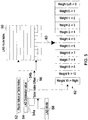
- the internal data packet traverses the internal network and at each stage in the network the packet's route value is used as an index 52 ( Figure 5 ) into a table 50 ( Figure 5 ) that is available on each switching element 40.
- Figure 5 illustrates the table 50, which could be implemented as a RAM but other storage mechanisms could be used instead.
- a value 60 returned from the table 50 describes how the LAG distribution value 54 should be interpreted at this stage in the network.
- a typical implementation might use a RAM with perhaps 72 bits of state or some similar width although any width could be used and would provide a different set of tradeoffs. It is quite possible that multiple formats might be used, selected using a type field, and this would give greater flexibility and control over different switching element configurations.
- a LAG width value 58 returned on the MAC address translation, can be used to increase the available information returned from the RAM.
- the LAG width value 58 can be used to select some of the bits of the LAG distribution value 54 to be included in the table index formed from the header route value 52. In this way a single very wide LAG, requiring detailed resolution from the LAG distribution value, will be represented over many table entries. For example, a very wide LAG could take 7 bits of the LAG distribution value 54 and use 128 entries in the table 50.
- Figure 5 shows how the full table index is formed, and illustrates how the LAG width value 58 is used to select a portion 54a of the LAG distribution value 54 and how the route value 52 that forms the base for the table index is modified by the selected portion 54a of the LAG distribution value 54.
- an addition 56 to the route value 52 is used to form the full RAM address but any function that provides a unique RAM address using the route value 52 and the selected portion 54a of the LAG distribution value 54 would be equally valid.
- Very wide LAGs will use a large portion of the total network resources and as such it is reasonable that a large proportion of the LAG table is used to describe a detailed division of the LAG distribution value.
- a narrow LAG will use a much smaller proportion of the total network resources and so it would be reasonable that a proportional amount of the LAG table is used to describe the LAG routing. Being a narrow LAG also means that a smaller total amount of table is necessary to give a reasonable distribution of packets over the whole LAG links range.
- a value 60 is read and used to interpret the other portion 54b of the LAG distribution value 54 identified from the LAG width value 58 as shown in Figure 5 .
- This other portion 54b is passed to weighted distribution logic 61, as shown in Figure 6 .
- This weighted distribution logic generates select signals 74 that are used to identify the switching element output ports the internal data packet should be directed towards at the next stage of the internal network.
- 13 select lines 74 are generated from 12 x 6 bit fields of the 72 bit table output 67.
- 6 bits 54b of the LAG distribution value 54 are used to interpret the 72 bit number from the table 50.
- Figure 7 shows another possible configuration of weighted distribution logic.
- 8 bits 54b of the LAG distribution value 54 are compared against 9 fields of the 72 bit example read value generating 10 output port select lines 88.
- Figures 6 and 7 have respective examples of possible values of the table entry.
- Each example has a left and right select signal as well as 11 port select signals 74 for Figure 6 , and 8 port select signals 88 for Figure 7 .
- the left and right values are an optimisation for use in networks like the Fat Tree network where these values would be assigned to adaptive up routes but they could be used for any network topology where multiple hops are required to reach the egress port. However, the left and right values could always select the same output port and do not need to generate an adaptive route.
- the read data returned from the table is divided into a number of fields. These fields mark the boundary between portions of the LAG distribution value 54.
- Each select signal 74;88 has 2 comparator functions 70,72;84,86 that allow the signal to be asserted when the LAG distribution value 54 is greater than or equal to the value on the right and less than the value on the left.
- Each field within the value 60 read from the table should be greater or equal to the field value to the right. In this way, only one select signal can be asserted for any given LAG value input into the logic.
- Figure 6 illustrates an example where all the field values are different from each other. In this example, a LAG distribution value 54 of 0x28 would select link 1 and a value of 0x05 would select Right Up Link.
- Figure 7 illustrates a different example.
- the 9 fields from the table are each 8 bits wide. Some of the fields have been programmed with the same value. This prevents the select signals that appear between identical values from being asserted for any value from the LAG distribution value 54. This allows links that appear within the range of a continuous wide LAG to be excluded from being part of that LAG.
- the mechanism as described allows a mix of any of the selected signals for a range of LAG distribution values 54.
- all the LAG traffic for all values of the LAG distribution values 54 should be directed to a single port.
- another special coding value can be used that breaks the normal rule of the fields always having a greater or equal value when moving from the right most field to the left most field.
- One possible coding is to use the maximum value on in the right field followed by one less than the maximum value in the field to the left of the right most field. If this is detected then any of the other field values could be used to identify a single output port to direct all the packets towards.
- Another special case that each of the select values needs to cope with is where an output should be selected for only the maximum value supplied from the LAG distribution value 54.
- a value of zero fed into the greater than comparator should be interpreted as 1 greater than the maximum value if the value on the right of the zero field is not zero. Then an output signal is asserted for this select signal if the LAG distribution value 54 into the weighted distribution logic has the maximum value.
- Such a weighted routing mechanism is applied at each switching element 40 within the internal network.
- the initial stages of the internal network would normally be configured always to generate a single upward value unless some of the LAG ports appear on the first network element.
- Figure 8 gives an example Fat Tree network with an example LAG mapped onto some of the ports.
- the structure of the network of Figure 8 is similar to that of Figure 4 , and comprises three levels 98, 99, 100 of switching elements 90 interconnected by internal network links 92.
- the LAG ports appear on switching elements A, C, F, G, H and J.
- the example shows an incoming data packet arriving on a port of switching element A. Being a packet connected directly to a true Ethernet link the frame is first encapsulated into an internal data packet. The destination MAC address of the incoming data packet is translated and, for this packet, a route to the example wide LAG is returned.
- the LAG distribution value 54 is generated according to the type of algorithm to be used returned with the translation.
- the route value 52 and the LAG distribution value 54 are put into the header of the resulting internal data packet, which is then passed on for routing.
- LAG there are 11 ports. This means the LAG distribution space must be divided into 11 roughly equal segments to provide an even distribution of data packets to all of the links in the LAG.
- switching element A 1/11ths worth of LAG data packets should be directed to the local link.
- the other 10/11ths worth should be sent upwards.
- the upward route could be any of the upward links and the 10/11ths worth selection could specify an adaptive selection of any of the upward links.
- the choice is the link directing the packet to switching element B3 but switching element B1 or B2 could have been used.
- the same table can be used for all the ports of a particular switching element.
- the tables in B1, B2 and B3 are loaded with the same values as they would respond in the same way to LAG packets arriving at their ports. If the LAG distribution value indicates the packet should move up the network then again an adaptive choice could be made allowing the packet to arrive at any of the top switching elements D1 to D9. The packet will then follow the same rules until it appears at the correct LAG port as described by the LAG distribution value. With this mechanism and any given route value and LAG distribution value, the packet will be routed to the correct LAG port from any position within the whole network.
- Each switching element output is given a LAG distribution value filter.
- the switching element output prepares data for transmission on a link. It does this for both internal links and Ethernet Bridge egress ports.
- the Ethernet Bridge egress ports connected to the external network also perform the unencapsulation function removing the header that had been added by the Ethernet ingress port.
- the LAG distribution value filter consists of two registers that hold the upper and lower limits of acceptable LAG distribution values that can be sent for this output port. If a LAG distribution value is less than the lower limit or is higher than the upper limit then the internal data packet must be discarded.
- the link is not an egress port of the Ethernet Bridge this is normally set to include all packets by setting the lower value to 0 and the upper value to the maximum value. If the output port is an egress port of the Bridge and has been assigned as one of the links in a wide LAG then the filter is set to the minimum and maximum values of the LAG distribution values that would normally direct packets to this link. Any internal data packets arriving at this link with the wrong value of the LAG distribution value are discarded. This means broadcasts and multicasts can send their packets to all the ports in the LAG and the Ethernet Frame will only be transmitted on the correct egress port. This gives the right function but it is inefficient as packets are transmitted on internal links that will only be discarded at the output egress port.
- the LAG filter for the internal output link can be set to include the inclusive range of all those LAG ports.
- the link from E to G in Figure 8 is an example of this.
- the output ports on E1 to E3 connected to G could set their output filters to only allow broadcast and multicast packets to be transmitted with a LAG distribution value valid for the LAG links connected to switching element G.
- Flood packets are different in that they are only generated when a MAC translation for a destination MAC address has not been learned in the MAC translation tables. This creates a problem because part of the returned translation includes the method for generating the LAG distribution value.
- the solution is to mark flood packets with a bit in the header for the internal encapsulation and to prevent any LAG filtering until the packets are received at the final Ethernet egress port. These ports "know" the correct distribution algorithm that should be applied and this can be recalculated using the values in the Ethernet frame that is about to be transmitted. A separate filter can then discard the packet if necessary.
- the configuration of a LAG is not likely to change frequently but occasionally links within the LAG may become broken or repaired and occasionally the LAG may be reconfigured to match new bandwidth requirements. It should be possible to make changes to the LAG without breaking other communications that could be occurring on other links within the Bridge. This is especially important if the bridge has a large number of ports. It should be possible to continue to use the LAG even during a reconfiguration. The reconfiguration will need to reassign the range of LAG distribution values each port within the LAG would expect to receive. In a large distributed system, perhaps with thousands of separate switching elements, it is impossible to update all the state of a wide LAG either atomically or simultaneously. An update of all the state could take seconds, and each link can typically transmit up to 80 million packets per second.
- the internal data packet header may then include another bit that is set for multicast packets.
- the bit selects between the "A" and "B" register set defining the necessary LAG packet filtering.
- a configuration bit is then provided in each Ethernet ingress port that can be set to either A or B.
- Embodiments of the present invention have been described using encapsulated data packets (the internal data packets). However, it will be readily appreciated that such techniques can be applied to unencapsulated data packets, in which case each switching element will include processing functionality that examines routing information in each data packet, and then uses that information to route the data packet to a port associated with the LAG.
Landscapes
- Engineering & Computer Science (AREA)
- Computer Networks & Wireless Communication (AREA)
- Signal Processing (AREA)
- Data Exchanges In Wide-Area Networks (AREA)
Claims (10)
- Ethernet-Switch für das Routen von Ethernet-Datenpaketen, wobei der Switch Folgendes umfasst:einen Dateneintrittsport;eine Vielzahl von Datenaustrittsports;ein Netzwerkgewebe, das den Dateneintrittsport mit den Datenaustrittsports verbindet und eine Vielzahl von miteinander verbundenen Schaltelementen (40) umfasst;eine Einkapselungseinrichtung, die für den Empfang eines vom Dateneintrittsport ankommenden Datenpakets angeschlossen ist undbetrieben werden kann, um ein internes Datenpaket zu erzeugen, das einen Headerteil und einen Nutzinformationsteil umfasst, wobei der Headerteil Routing-Informationen über eine Route durch die miteinander verbundenen Schaltelementen (40) einschließt und von den Routing-Informationen eines ankommenden Datenpakets abgeleitet wird,und der Nutzinformationsteil das ankommende Datenpaket umfasst;wobei die Einkapselungseinrichtung auch betrieben werden kann, um zu bestimmen, ob die Routing-Informationen des ankommenden Datenpakets sich auf eine Linkaggregationsgruppe beziehen, die mehrere Links aufweist, die derselben zugeordnet sind, und, falls ja, um Informationen der Linkaggregationsgruppe zu erzeugen, die einen Netzwerkroutenwert für die Aufnahme in den Header des internen Datenpakets einschließen;
wobei ein Verteilungswert (54) für das Bestimmen der Auswahl von einem der Links verwendet wird, die der Linkaggregationsgruppe zum Routen des betreffenden Datenpakets zugeordnet sind; und
wobei jedes Schaltelement (40) des Netzwerkgewebes Speichermittel einschließt, die betrieben werden können, um Ausgabeinformationen, die für eine Ausgaberoute bezeichnend sind, von dem betreffenden Schaltelement (40) zu speichern, wobei das Schaltelement (40) betreiben werden kann, um auf die gespeicherte Ausgabeinformationen in Abhängigkeit der empfangenen Informationen der Linkaggregationsgruppe zuzugreifen, dadurch gekennzeichnet, dass die Einkapselungseinrichtung außerdem betrieben werden kann, um einen Algorithmus der Linkaggregationsgruppe aus den Routing-Informationen eines ankommenden Datenpakets zu bestimmen und um den ausgewählten Algorithmus der Linkaggregationsgruppe zum Bestimmen des Verteilungswerts (54) zu verwenden, und um dem Header des internen Datenpakets den Verteilungswert (54) hinzuzufügen, wobei der Verteilungswert (54) eine bevorzugte Verteilung über die Austrittsports bereitstellt, die zum Bilden der Linkaggregationsgruppe verwendet wird. - Ethernet-Switch nach Anspruch 1, wobei solche Informationen der Linkaggregationsgruppe nur einmal, beim Zugang zum Switch, für ein bestimmtes ankommendes Datenpaket erzeugt werden.
- Ethernet-Switch nach Anspruch 1, wobei die Einkapselungseinrichtung betrieben werden kann, um einen Breitenwert (58) der Linkaggregationsgruppe aus den Routing-Informationen des ankommenden Datenpakets zu bestimmen, wobei der Breitenwert (58) für eine Menge an Informationen der Linkaggregationsgruppe bezeichnend ist, die für das Zugreifen auf die gespeicherten Ausgabeinformationen zu verwenden sind.
- Ethernet-Switch nach Anspruch 3, wobei jedes Schaltelement (40) eine gewichtete Verteilungslogik umfasst, die betrieben werden kann, um ein Signal für die Ausgabeportwahl in Abhängigkeit der abgerufenen Ausgabeinformationen zu erzeugen.
- Ethernet-Switch nach Anspruch 3 oder 4, wobei jedes Schaltelement (40) einen Datenpaketfilter umfasst, der betrieben werden kann, um Datenpakete in Abhängigkeit des Verteilungswerts, der denselben zugeordnet ist, zu verwerfen.
- Verfahren zum Routen von Ethernet-Datenpaketen in einem Ethernet-Switch, der einen Dateneintrittsport, eine Vielzahl von Datenaustrittsports und ein Netzwerkgewebe aufweist, das den Dateneintrittsport mit den Datenaustrittsports verbindet und eine Vielzahl von miteinander verbundenen Schaltelementen (40) umfasst, wobei das Verfahren die folgenden Schritte umfasst:Empfangen eines ankommenden Datenpakets;Erzeugen eines internen Datenpakets, das einen Headerteil und einen Nutzinformationsteil umfasst, wobei der Headerteil Routing-Informationen über eine Route durch die miteinander verbundenen Schaltelementen einschließt und von den Routing-Informationen eines ankommenden Datenpakets abgeleitet wird, und der Nutzinformationsteil das ankommende Datenpaket umfasst;Bestimmen, ob die Routing-Informationen des ankommenden Datenpakets sich auf eine Linkaggregationsgruppe beziehen, die mehrere Austrittsports aufweist, die derselben zugeordnet sind, und, falls ja, Erzeugen von Informationen der Linkaggregationsgruppe für die Aufnahme in den Header des internen Datenpakets, wobei die Informationen der Linkaggregationsgruppe einen Netzwerkroutenwert und einen Verteilungswert (54) für die Verwendung beim Bestimmen der Auswahl des einen der Austrittsports einschließt, die der Linkaggregationsgruppe zum Routen des betreffenden Datenpakets zugeordnet sind;Routen des internen Datenpakets durch das Netzwerkgewebe unter Verwendung der Routing-Informationen; undRouten des internen Datenpakets zum Austrittsport, der durch dieInformationen der Linkaggregationsgruppe bestimmt wird;wobei jedes Schaltelement (40) des Netzwerkgewebes Speichermittel einschließt, die betrieben werden können, um Ausgabeinformationen, die für eine Ausgaberoute bezeichnend sind, von dem betreffenden Schaltelement zu speichern, und wobei das Verfahren außerdem das Zugreifen auf die gespeicherten Ausgabeinformationen in Abhängigkeit der empfangenen Informationen der Linkaggregationsgruppe umfasst, wobei das Verfahren dadurch gekennzeichnet ist, dass der Verteilungswert (54) für das betreffende Datenpaket bestimmt wird, indem zuerst ein Algorithmus der Linkaggregationsgruppe, basierend auf den Routing-Informationen des ankommenden Datenpakets, ausgewählt und anschließend der ausgewählte Algorithmus der Linkaggregationsgruppe zum Bestimmen des Verteilungswerts (54) verwendet wird, der dann dem Header des internen Datenpakets hinzugefügt wird, und der eine bevorzugte Verteilung über die Austrittsports bereitstellt, die zum Bilden der Linkaggregationsgruppe verwendet wird.
- Verfahren nach Anspruch 6, wobei solche Informationen der Linkaggregationsgruppe nur einmal, beim Zugang zum Switch, für ein bestimmtes ankommendes Datenpaket erzeugt werden.
- Verfahren nach Anspruch 6, das außerdem das Bestimmen eines Breitenwerts (58) der Linkaggregationsgruppe aus den Routing-Informationen des ankommenden Datenpakets umfasst, wobei der Breitenwert für eine Menge an Informationen der Linkaggregationsgruppe bezeichnend ist, die für das Zugreifen auf die gespeicherten Ausgabeinformationen zu verwenden sind.
- Verfahren nach Anspruch 8, das außerdem das Erzeugen eines Signals für die Ausgabeportwahl in Abhängigkeit der abgerufenen Ausgabeinformationen umfasst.
- Verfahren nach Anspruch 8 oder 9, das außerdem das Verwerfen von Datenpaketen in Abhängigkeit des Verteilungswerts, der denselben zugeordnet ist, umfasst.
Applications Claiming Priority (2)
| Application Number | Priority Date | Filing Date | Title |
|---|---|---|---|
| GB1012037.6A GB2482118B (en) | 2010-07-19 | 2010-07-19 | Ethernet switch with link aggregation group facility |
| PCT/GB2011/051331 WO2012010868A1 (en) | 2010-07-19 | 2011-07-15 | Ethernet switch and method for routing ethernet data packets |
Publications (2)
| Publication Number | Publication Date |
|---|---|
| EP2596603A1 EP2596603A1 (de) | 2013-05-29 |
| EP2596603B1 true EP2596603B1 (de) | 2018-10-03 |
Family
ID=42735092
Family Applications (1)
| Application Number | Title | Priority Date | Filing Date |
|---|---|---|---|
| EP11745568.3A Active EP2596603B1 (de) | 2010-07-19 | 2011-07-15 | Ethernet-schalter und verfahren zum routen von ethernet-datenpaketen |
Country Status (5)
| Country | Link |
|---|---|
| US (1) | US9800499B2 (de) |
| EP (1) | EP2596603B1 (de) |
| CN (1) | CN103026666A (de) |
| GB (1) | GB2482118B (de) |
| WO (1) | WO2012010868A1 (de) |
Families Citing this family (10)
| Publication number | Priority date | Publication date | Assignee | Title |
|---|---|---|---|---|
| JP5765623B2 (ja) * | 2011-07-19 | 2015-08-19 | 日立金属株式会社 | ネットワークシステム |
| JP5935572B2 (ja) | 2012-07-27 | 2016-06-15 | 富士通株式会社 | 基地局装置及びパケット振分け方法 |
| CN103780510B (zh) * | 2012-10-19 | 2020-03-17 | 中兴通讯股份有限公司 | 链路聚合组中流量路径的协商方法及装置 |
| US20140192635A1 (en) * | 2013-01-04 | 2014-07-10 | International Business Machines Corporation | Start-up delay for event-driven virtual link aggregation |
| CN103152260B (zh) | 2013-02-21 | 2019-02-15 | 中兴通讯股份有限公司 | 报文转发系统、方法及装置 |
| US9473389B2 (en) | 2013-05-30 | 2016-10-18 | Hewlett Packard Enterprise Development Lp | Excluding a data frame from a link aggregation group |
| CN103441961A (zh) * | 2013-07-11 | 2013-12-11 | 盛科网络(苏州)有限公司 | 基于多条处理逻辑线实现高速宽带的方法和装置 |
| US10291521B1 (en) | 2014-06-30 | 2019-05-14 | Juniper Networks, Inc. | Multi-chassis link aggregation groups with more than two chassis |
| CN105577562B (zh) * | 2014-10-17 | 2020-02-14 | 中兴通讯股份有限公司 | 业务数据流的发送、转发方法及装置 |
| US10673744B2 (en) * | 2015-09-23 | 2020-06-02 | Extreme Networks, Inc. | Methods, systems, and computer readable media for advanced distribution in a link aggregation group |
Family Cites Families (7)
| Publication number | Priority date | Publication date | Assignee | Title |
|---|---|---|---|---|
| US6973082B2 (en) * | 2002-02-01 | 2005-12-06 | Fujitsu Limited | Forwarding packets to aggregated links using distributed ingress card processing |
| EP1673683A4 (de) * | 2003-10-14 | 2010-06-02 | Raptor Networks Technology Inc | Vermittlungssystem mit verteiltem koppelfeld |
| US7974202B2 (en) * | 2005-05-06 | 2011-07-05 | Corrigent Systems, Ltd. | Tunnel provisioning with link aggregation |
| US20070053294A1 (en) | 2005-09-02 | 2007-03-08 | Michael Ho | Network load balancing apparatus, systems, and methods |
| US7697528B2 (en) * | 2005-11-01 | 2010-04-13 | Nortel Networks Limited | Multilink trunking for encapsulated traffic |
| US8054830B2 (en) * | 2005-12-07 | 2011-11-08 | Alcatel Lucent | Managing the distribution of control protocol information in a network node |
| US7593400B2 (en) | 2006-05-19 | 2009-09-22 | Corrigent Systems Ltd. | MAC address learning in a distributed bridge |
-
2010
- 2010-07-19 GB GB1012037.6A patent/GB2482118B/en active Active
-
2011
- 2011-07-15 US US13/704,206 patent/US9800499B2/en active Active
- 2011-07-15 CN CN2011800351055A patent/CN103026666A/zh active Pending
- 2011-07-15 EP EP11745568.3A patent/EP2596603B1/de active Active
- 2011-07-15 WO PCT/GB2011/051331 patent/WO2012010868A1/en active Application Filing
Non-Patent Citations (1)
| Title |
|---|
| None * |
Also Published As
| Publication number | Publication date |
|---|---|
| CN103026666A (zh) | 2013-04-03 |
| US20130215896A1 (en) | 2013-08-22 |
| GB2482118A (en) | 2012-01-25 |
| GB201012037D0 (en) | 2010-09-01 |
| WO2012010868A1 (en) | 2012-01-26 |
| EP2596603A1 (de) | 2013-05-29 |
| US9800499B2 (en) | 2017-10-24 |
| GB2482118B (en) | 2017-03-01 |
Similar Documents
| Publication | Publication Date | Title |
|---|---|---|
| EP2596603B1 (de) | Ethernet-schalter und verfahren zum routen von ethernet-datenpaketen | |
| EP3949293B1 (de) | Slice-basierte leitweglenkung | |
| CN109861926B (zh) | 报文的发送、处理方法、装置、节点、处理系统和介质 | |
| US20210367853A1 (en) | Transmit specific traffic along blocked link | |
| US8576853B2 (en) | Two-layer switch apparatus avoiding first layer inter-switch traffic in steering packets through the apparatus | |
| KR101503629B1 (ko) | 주소 기반 캐리어 네트워크의 구별 전달 | |
| JP4076586B2 (ja) | マルチレイヤ・ネットワーク要素用のシステムおよび方法 | |
| CN1969509B (zh) | 用于集中分组处理的网络设备体系结构 | |
| JP3842303B2 (ja) | 多層ネットワーク要素のためのシステムおよび方法 | |
| US8619769B2 (en) | Packet-layer transparent packet-switching network | |
| US8446822B2 (en) | Pinning and protection on link aggregation groups | |
| EP0937353B1 (de) | Leitweglenkung in einem verteilten mehrschicht-netzelement | |
| US7369561B2 (en) | Apparatus and method for route summarization and distribution in a massively parallel router | |
| US20120076014A1 (en) | Method and apparatus for traffic engineering in shortest path bridged networks | |
| EP3072274B1 (de) | Quellenrouting mit entropieheader | |
| JP5542927B2 (ja) | ノード間リンク集合システムおよび方法 | |
| CN108353026B (zh) | 用于链路聚合组中的高级分布的方法、系统和计算机可读介质 | |
| KR101228284B1 (ko) | 데이타 통신 시스템 및 방법 | |
| US20180026878A1 (en) | Scalable deadlock-free deterministic minimal-path routing for dragonfly networks | |
| EP3648419B1 (de) | Verfahren und vorrichtungen zum routen von datenpaketen in einer netzwerktopologie | |
| US7486672B2 (en) | Apparatus and method for searching trie trees using masks with non-symbol boundaries and flooding default routes in a massively parallel router | |
| CN114401222B (zh) | 一种基于策略路由的数据转发方法、装置及存储介质 | |
| US9270577B2 (en) | Selection of one of first and second links between first and second network devices |
Legal Events
| Date | Code | Title | Description |
|---|---|---|---|
| PUAI | Public reference made under article 153(3) epc to a published international application that has entered the european phase |
Free format text: ORIGINAL CODE: 0009012 |
|
| 17P | Request for examination filed |
Effective date: 20130109 |
|
| AK | Designated contracting states |
Kind code of ref document: A1 Designated state(s): AL AT BE BG CH CY CZ DE DK EE ES FI FR GB GR HR HU IE IS IT LI LT LU LV MC MK MT NL NO PL PT RO RS SE SI SK SM TR |
|
| DAX | Request for extension of the european patent (deleted) | ||
| 19U | Interruption of proceedings before grant |
Effective date: 20131004 |
|
| 19W | Proceedings resumed before grant after interruption of proceedings |
Effective date: 20140303 |
|
| REG | Reference to a national code |
Ref country code: HK Ref legal event code: DE Ref document number: 1186315 Country of ref document: HK |
|
| RAP1 | Party data changed (applicant data changed or rights of an application transferred) |
Owner name: CRAY UK LIMITED |
|
| STAA | Information on the status of an ep patent application or granted ep patent |
Free format text: STATUS: EXAMINATION IS IN PROGRESS |
|
| 17Q | First examination report despatched |
Effective date: 20170213 |
|
| RAP1 | Party data changed (applicant data changed or rights of an application transferred) |
Owner name: CRAY UK LIMITED |
|
| REG | Reference to a national code |
Ref country code: DE Ref legal event code: R079 Ref document number: 602011052555 Country of ref document: DE Free format text: PREVIOUS MAIN CLASS: H04L0012560000 Ipc: H04L0012741000 |
|
| RIC1 | Information provided on ipc code assigned before grant |
Ipc: H04L 12/741 20130101AFI20180308BHEP Ipc: H04L 12/931 20130101ALI20180308BHEP Ipc: H04L 12/709 20130101ALI20180308BHEP Ipc: H04L 12/947 20130101ALI20180308BHEP Ipc: H04L 12/46 20060101ALI20180308BHEP |
|
| GRAP | Despatch of communication of intention to grant a patent |
Free format text: ORIGINAL CODE: EPIDOSNIGR1 |
|
| STAA | Information on the status of an ep patent application or granted ep patent |
Free format text: STATUS: GRANT OF PATENT IS INTENDED |
|
| INTG | Intention to grant announced |
Effective date: 20180424 |
|
| GRAS | Grant fee paid |
Free format text: ORIGINAL CODE: EPIDOSNIGR3 |
|
| GRAA | (expected) grant |
Free format text: ORIGINAL CODE: 0009210 |
|
| STAA | Information on the status of an ep patent application or granted ep patent |
Free format text: STATUS: THE PATENT HAS BEEN GRANTED |
|
| AK | Designated contracting states |
Kind code of ref document: B1 Designated state(s): AL AT BE BG CH CY CZ DE DK EE ES FI FR GB GR HR HU IE IS IT LI LT LU LV MC MK MT NL NO PL PT RO RS SE SI SK SM TR |
|
| REG | Reference to a national code |
Ref country code: GB Ref legal event code: FG4D |
|
| REG | Reference to a national code |
Ref country code: CH Ref legal event code: EP Ref country code: AT Ref legal event code: REF Ref document number: 1049846 Country of ref document: AT Kind code of ref document: T Effective date: 20181015 |
|
| REG | Reference to a national code |
Ref country code: DE Ref legal event code: R096 Ref document number: 602011052555 Country of ref document: DE |
|
| REG | Reference to a national code |
Ref country code: IE Ref legal event code: FG4D |
|
| REG | Reference to a national code |
Ref country code: CH Ref legal event code: NV Representative=s name: OFFICE ERNEST T. FREYLINGER S.A., CH |
|
| REG | Reference to a national code |
Ref country code: CH Ref legal event code: PK Free format text: BERICHTIGUNGEN |
|
| REG | Reference to a national code |
Ref country code: NL Ref legal event code: MP Effective date: 20181003 |
|
| RIC2 | Information provided on ipc code assigned after grant |
Ipc: H04L 12/931 20130101ALI20180308BHEP Ipc: H04L 12/741 20130101AFI20180308BHEP Ipc: H04L 12/947 20130101ALI20180308BHEP Ipc: H04L 12/46 20060101ALI20180308BHEP Ipc: H04L 12/709 20130101ALI20180308BHEP |
|
| REG | Reference to a national code |
Ref country code: LT Ref legal event code: MG4D |
|
| REG | Reference to a national code |
Ref country code: AT Ref legal event code: MK05 Ref document number: 1049846 Country of ref document: AT Kind code of ref document: T Effective date: 20181003 |
|
| PG25 | Lapsed in a contracting state [announced via postgrant information from national office to epo] |
Ref country code: NL Free format text: LAPSE BECAUSE OF FAILURE TO SUBMIT A TRANSLATION OF THE DESCRIPTION OR TO PAY THE FEE WITHIN THE PRESCRIBED TIME-LIMIT Effective date: 20181003 |
|
| PG25 | Lapsed in a contracting state [announced via postgrant information from national office to epo] |
Ref country code: LT Free format text: LAPSE BECAUSE OF FAILURE TO SUBMIT A TRANSLATION OF THE DESCRIPTION OR TO PAY THE FEE WITHIN THE PRESCRIBED TIME-LIMIT Effective date: 20181003 Ref country code: PL Free format text: LAPSE BECAUSE OF FAILURE TO SUBMIT A TRANSLATION OF THE DESCRIPTION OR TO PAY THE FEE WITHIN THE PRESCRIBED TIME-LIMIT Effective date: 20181003 Ref country code: BG Free format text: LAPSE BECAUSE OF FAILURE TO SUBMIT A TRANSLATION OF THE DESCRIPTION OR TO PAY THE FEE WITHIN THE PRESCRIBED TIME-LIMIT Effective date: 20190103 Ref country code: NO Free format text: LAPSE BECAUSE OF FAILURE TO SUBMIT A TRANSLATION OF THE DESCRIPTION OR TO PAY THE FEE WITHIN THE PRESCRIBED TIME-LIMIT Effective date: 20190103 Ref country code: HR Free format text: LAPSE BECAUSE OF FAILURE TO SUBMIT A TRANSLATION OF THE DESCRIPTION OR TO PAY THE FEE WITHIN THE PRESCRIBED TIME-LIMIT Effective date: 20181003 Ref country code: AT Free format text: LAPSE BECAUSE OF FAILURE TO SUBMIT A TRANSLATION OF THE DESCRIPTION OR TO PAY THE FEE WITHIN THE PRESCRIBED TIME-LIMIT Effective date: 20181003 Ref country code: IS Free format text: LAPSE BECAUSE OF FAILURE TO SUBMIT A TRANSLATION OF THE DESCRIPTION OR TO PAY THE FEE WITHIN THE PRESCRIBED TIME-LIMIT Effective date: 20190203 Ref country code: ES Free format text: LAPSE BECAUSE OF FAILURE TO SUBMIT A TRANSLATION OF THE DESCRIPTION OR TO PAY THE FEE WITHIN THE PRESCRIBED TIME-LIMIT Effective date: 20181003 Ref country code: CZ Free format text: LAPSE BECAUSE OF FAILURE TO SUBMIT A TRANSLATION OF THE DESCRIPTION OR TO PAY THE FEE WITHIN THE PRESCRIBED TIME-LIMIT Effective date: 20181003 Ref country code: LV Free format text: LAPSE BECAUSE OF FAILURE TO SUBMIT A TRANSLATION OF THE DESCRIPTION OR TO PAY THE FEE WITHIN THE PRESCRIBED TIME-LIMIT Effective date: 20181003 Ref country code: FI Free format text: LAPSE BECAUSE OF FAILURE TO SUBMIT A TRANSLATION OF THE DESCRIPTION OR TO PAY THE FEE WITHIN THE PRESCRIBED TIME-LIMIT Effective date: 20181003 |
|
| PG25 | Lapsed in a contracting state [announced via postgrant information from national office to epo] |
Ref country code: RS Free format text: LAPSE BECAUSE OF FAILURE TO SUBMIT A TRANSLATION OF THE DESCRIPTION OR TO PAY THE FEE WITHIN THE PRESCRIBED TIME-LIMIT Effective date: 20181003 Ref country code: AL Free format text: LAPSE BECAUSE OF FAILURE TO SUBMIT A TRANSLATION OF THE DESCRIPTION OR TO PAY THE FEE WITHIN THE PRESCRIBED TIME-LIMIT Effective date: 20181003 Ref country code: SE Free format text: LAPSE BECAUSE OF FAILURE TO SUBMIT A TRANSLATION OF THE DESCRIPTION OR TO PAY THE FEE WITHIN THE PRESCRIBED TIME-LIMIT Effective date: 20181003 Ref country code: GR Free format text: LAPSE BECAUSE OF FAILURE TO SUBMIT A TRANSLATION OF THE DESCRIPTION OR TO PAY THE FEE WITHIN THE PRESCRIBED TIME-LIMIT Effective date: 20190104 Ref country code: PT Free format text: LAPSE BECAUSE OF FAILURE TO SUBMIT A TRANSLATION OF THE DESCRIPTION OR TO PAY THE FEE WITHIN THE PRESCRIBED TIME-LIMIT Effective date: 20190203 |
|
| REG | Reference to a national code |
Ref country code: DE Ref legal event code: R097 Ref document number: 602011052555 Country of ref document: DE |
|
| PG25 | Lapsed in a contracting state [announced via postgrant information from national office to epo] |
Ref country code: IT Free format text: LAPSE BECAUSE OF FAILURE TO SUBMIT A TRANSLATION OF THE DESCRIPTION OR TO PAY THE FEE WITHIN THE PRESCRIBED TIME-LIMIT Effective date: 20181003 Ref country code: DK Free format text: LAPSE BECAUSE OF FAILURE TO SUBMIT A TRANSLATION OF THE DESCRIPTION OR TO PAY THE FEE WITHIN THE PRESCRIBED TIME-LIMIT Effective date: 20181003 |
|
| PLBE | No opposition filed within time limit |
Free format text: ORIGINAL CODE: 0009261 |
|
| STAA | Information on the status of an ep patent application or granted ep patent |
Free format text: STATUS: NO OPPOSITION FILED WITHIN TIME LIMIT |
|
| PG25 | Lapsed in a contracting state [announced via postgrant information from national office to epo] |
Ref country code: RO Free format text: LAPSE BECAUSE OF FAILURE TO SUBMIT A TRANSLATION OF THE DESCRIPTION OR TO PAY THE FEE WITHIN THE PRESCRIBED TIME-LIMIT Effective date: 20181003 Ref country code: SM Free format text: LAPSE BECAUSE OF FAILURE TO SUBMIT A TRANSLATION OF THE DESCRIPTION OR TO PAY THE FEE WITHIN THE PRESCRIBED TIME-LIMIT Effective date: 20181003 Ref country code: SK Free format text: LAPSE BECAUSE OF FAILURE TO SUBMIT A TRANSLATION OF THE DESCRIPTION OR TO PAY THE FEE WITHIN THE PRESCRIBED TIME-LIMIT Effective date: 20181003 Ref country code: EE Free format text: LAPSE BECAUSE OF FAILURE TO SUBMIT A TRANSLATION OF THE DESCRIPTION OR TO PAY THE FEE WITHIN THE PRESCRIBED TIME-LIMIT Effective date: 20181003 |
|
| 26N | No opposition filed |
Effective date: 20190704 |
|
| PG25 | Lapsed in a contracting state [announced via postgrant information from national office to epo] |
Ref country code: SI Free format text: LAPSE BECAUSE OF FAILURE TO SUBMIT A TRANSLATION OF THE DESCRIPTION OR TO PAY THE FEE WITHIN THE PRESCRIBED TIME-LIMIT Effective date: 20181003 |
|
| PG25 | Lapsed in a contracting state [announced via postgrant information from national office to epo] |
Ref country code: MC Free format text: LAPSE BECAUSE OF FAILURE TO SUBMIT A TRANSLATION OF THE DESCRIPTION OR TO PAY THE FEE WITHIN THE PRESCRIBED TIME-LIMIT Effective date: 20181003 |
|
| PG25 | Lapsed in a contracting state [announced via postgrant information from national office to epo] |
Ref country code: TR Free format text: LAPSE BECAUSE OF FAILURE TO SUBMIT A TRANSLATION OF THE DESCRIPTION OR TO PAY THE FEE WITHIN THE PRESCRIBED TIME-LIMIT Effective date: 20181003 |
|
| REG | Reference to a national code |
Ref country code: BE Ref legal event code: MM Effective date: 20190731 |
|
| PG25 | Lapsed in a contracting state [announced via postgrant information from national office to epo] |
Ref country code: BE Free format text: LAPSE BECAUSE OF NON-PAYMENT OF DUE FEES Effective date: 20190731 Ref country code: LU Free format text: LAPSE BECAUSE OF NON-PAYMENT OF DUE FEES Effective date: 20190715 |
|
| PG25 | Lapsed in a contracting state [announced via postgrant information from national office to epo] |
Ref country code: IE Free format text: LAPSE BECAUSE OF NON-PAYMENT OF DUE FEES Effective date: 20190715 |
|
| PGFP | Annual fee paid to national office [announced via postgrant information from national office to epo] |
Ref country code: CH Payment date: 20200623 Year of fee payment: 10 |
|
| REG | Reference to a national code |
Ref country code: DE Ref legal event code: R082 Ref document number: 602011052555 Country of ref document: DE Representative=s name: FLEUCHAUS & GALLO PARTNERSCHAFT MBB - PATENT- , DE Ref country code: DE Ref legal event code: R082 Ref document number: 602011052555 Country of ref document: DE Representative=s name: FLEUCHAUS & GALLO PARTNERSCHAFT MBB PATENTANWA, DE Ref country code: DE Ref legal event code: R082 Ref document number: 602011052555 Country of ref document: DE Representative=s name: PROCK, THOMAS, DR., GB |
|
| PG25 | Lapsed in a contracting state [announced via postgrant information from national office to epo] |
Ref country code: CY Free format text: LAPSE BECAUSE OF FAILURE TO SUBMIT A TRANSLATION OF THE DESCRIPTION OR TO PAY THE FEE WITHIN THE PRESCRIBED TIME-LIMIT Effective date: 20181003 |
|
| PG25 | Lapsed in a contracting state [announced via postgrant information from national office to epo] |
Ref country code: MT Free format text: LAPSE BECAUSE OF FAILURE TO SUBMIT A TRANSLATION OF THE DESCRIPTION OR TO PAY THE FEE WITHIN THE PRESCRIBED TIME-LIMIT Effective date: 20181003 Ref country code: HU Free format text: LAPSE BECAUSE OF FAILURE TO SUBMIT A TRANSLATION OF THE DESCRIPTION OR TO PAY THE FEE WITHIN THE PRESCRIBED TIME-LIMIT; INVALID AB INITIO Effective date: 20110715 |
|
| REG | Reference to a national code |
Ref country code: GB Ref legal event code: 732E Free format text: REGISTERED BETWEEN 20211028 AND 20211103 |
|
| REG | Reference to a national code |
Ref country code: DE Ref legal event code: R079 Ref document number: 602011052555 Country of ref document: DE Free format text: PREVIOUS MAIN CLASS: H04L0012741000 Ipc: H04L0045740000 |
|
| REG | Reference to a national code |
Ref country code: DE Ref legal event code: R081 Ref document number: 602011052555 Country of ref document: DE Owner name: HEWLETT PACKARD ENTERPRISE DEVELOPEMENT LP, HO, US Free format text: FORMER OWNER: CRAY UK LTD., LONDON, GB |
|
| REG | Reference to a national code |
Ref country code: CH Ref legal event code: PL |
|
| PG25 | Lapsed in a contracting state [announced via postgrant information from national office to epo] |
Ref country code: LI Free format text: LAPSE BECAUSE OF NON-PAYMENT OF DUE FEES Effective date: 20210731 Ref country code: CH Free format text: LAPSE BECAUSE OF NON-PAYMENT OF DUE FEES Effective date: 20210731 |
|
| PG25 | Lapsed in a contracting state [announced via postgrant information from national office to epo] |
Ref country code: MK Free format text: LAPSE BECAUSE OF FAILURE TO SUBMIT A TRANSLATION OF THE DESCRIPTION OR TO PAY THE FEE WITHIN THE PRESCRIBED TIME-LIMIT Effective date: 20181003 |
|
| REG | Reference to a national code |
Ref country code: DE Ref legal event code: R082 Ref document number: 602011052555 Country of ref document: DE Representative=s name: FLEUCHAUS & GALLO PARTNERSCHAFT MBB - PATENT- , DE Ref country code: DE Ref legal event code: R082 Ref document number: 602011052555 Country of ref document: DE Representative=s name: FLEUCHAUS & GALLO PARTNERSCHAFT MBB PATENTANWA, DE |
|
| PGFP | Annual fee paid to national office [announced via postgrant information from national office to epo] |
Ref country code: DE Payment date: 20240730 Year of fee payment: 14 |
|
| PGFP | Annual fee paid to national office [announced via postgrant information from national office to epo] |
Ref country code: GB Payment date: 20240724 Year of fee payment: 14 |
|
| PGFP | Annual fee paid to national office [announced via postgrant information from national office to epo] |
Ref country code: FR Payment date: 20240725 Year of fee payment: 14 |