EP2594937B1 - Gassensor zur Detektion von Wasserstoffgas - Google Patents
Gassensor zur Detektion von Wasserstoffgas Download PDFInfo
- Publication number
- EP2594937B1 EP2594937B1 EP11189576.9A EP11189576A EP2594937B1 EP 2594937 B1 EP2594937 B1 EP 2594937B1 EP 11189576 A EP11189576 A EP 11189576A EP 2594937 B1 EP2594937 B1 EP 2594937B1
- Authority
- EP
- European Patent Office
- Prior art keywords
- layer
- gas sensor
- hydrogen
- gas
- sensor
- Prior art date
- Legal status (The legal status is an assumption and is not a legal conclusion. Google has not performed a legal analysis and makes no representation as to the accuracy of the status listed.)
- Not-in-force
Links
- 239000007789 gas Substances 0.000 title claims description 122
- UFHFLCQGNIYNRP-UHFFFAOYSA-N Hydrogen Chemical compound [H][H] UFHFLCQGNIYNRP-UHFFFAOYSA-N 0.000 title claims description 86
- 238000001514 detection method Methods 0.000 title description 4
- 239000010410 layer Substances 0.000 claims description 120
- 239000001257 hydrogen Substances 0.000 claims description 80
- 229910052739 hydrogen Inorganic materials 0.000 claims description 80
- 239000002346 layers by function Substances 0.000 claims description 44
- 239000003054 catalyst Substances 0.000 claims description 30
- 239000000758 substrate Substances 0.000 claims description 22
- 229920001343 polytetrafluoroethylene Polymers 0.000 claims description 15
- -1 polytetrafluorethylene Polymers 0.000 claims description 12
- 229910052751 metal Inorganic materials 0.000 claims description 10
- 239000002184 metal Substances 0.000 claims description 10
- 229910052763 palladium Inorganic materials 0.000 claims description 9
- 229910052719 titanium Inorganic materials 0.000 claims description 8
- 239000011521 glass Substances 0.000 claims description 7
- 229910052697 platinum Inorganic materials 0.000 claims description 7
- 229910052720 vanadium Inorganic materials 0.000 claims description 7
- 230000003321 amplification Effects 0.000 claims description 6
- 238000003199 nucleic acid amplification method Methods 0.000 claims description 6
- 238000010521 absorption reaction Methods 0.000 claims description 4
- 239000000463 material Substances 0.000 claims description 4
- 239000004417 polycarbonate Substances 0.000 claims description 4
- 229920000515 polycarbonate Polymers 0.000 claims description 4
- VYPSYNLAJGMNEJ-UHFFFAOYSA-N Silicium dioxide Chemical compound O=[Si]=O VYPSYNLAJGMNEJ-UHFFFAOYSA-N 0.000 claims description 3
- 239000010980 sapphire Substances 0.000 claims description 3
- 229910052594 sapphire Inorganic materials 0.000 claims description 3
- 229910052723 transition metal Inorganic materials 0.000 claims description 3
- 150000003624 transition metals Chemical class 0.000 claims description 3
- 229910001260 Pt alloy Inorganic materials 0.000 claims description 2
- 239000000203 mixture Substances 0.000 description 26
- 238000005259 measurement Methods 0.000 description 22
- 239000010936 titanium Substances 0.000 description 21
- KDLHZDBZIXYQEI-UHFFFAOYSA-N Palladium Chemical compound [Pd] KDLHZDBZIXYQEI-UHFFFAOYSA-N 0.000 description 19
- 239000011777 magnesium Substances 0.000 description 15
- 230000008859 change Effects 0.000 description 14
- 239000004810 polytetrafluoroethylene Substances 0.000 description 12
- 230000007774 longterm Effects 0.000 description 11
- 230000004044 response Effects 0.000 description 10
- 150000004678 hydrides Chemical class 0.000 description 9
- 150000002431 hydrogen Chemical class 0.000 description 8
- BASFCYQUMIYNBI-UHFFFAOYSA-N platinum Chemical compound [Pt] BASFCYQUMIYNBI-UHFFFAOYSA-N 0.000 description 7
- 230000008021 deposition Effects 0.000 description 6
- 230000008901 benefit Effects 0.000 description 5
- 238000003795 desorption Methods 0.000 description 5
- 230000002349 favourable effect Effects 0.000 description 5
- PXHVJJICTQNCMI-UHFFFAOYSA-N nickel Substances [Ni] PXHVJJICTQNCMI-UHFFFAOYSA-N 0.000 description 5
- 230000003287 optical effect Effects 0.000 description 5
- 229910019089 Mg-Fe Inorganic materials 0.000 description 4
- 239000010409 thin film Substances 0.000 description 4
- 230000007704 transition Effects 0.000 description 4
- 229910000861 Mg alloy Inorganic materials 0.000 description 3
- 230000004913 activation Effects 0.000 description 3
- 229910045601 alloy Inorganic materials 0.000 description 3
- 239000000956 alloy Substances 0.000 description 3
- 238000010586 diagram Methods 0.000 description 3
- 229910052737 gold Inorganic materials 0.000 description 3
- 239000010931 gold Substances 0.000 description 3
- 230000035484 reaction time Effects 0.000 description 3
- IJGRMHOSHXDMSA-UHFFFAOYSA-N Atomic nitrogen Chemical compound N#N IJGRMHOSHXDMSA-UHFFFAOYSA-N 0.000 description 2
- 229910001069 Ti alloy Inorganic materials 0.000 description 2
- QVGXLLKOCUKJST-UHFFFAOYSA-N atomic oxygen Chemical compound [O] QVGXLLKOCUKJST-UHFFFAOYSA-N 0.000 description 2
- 238000006243 chemical reaction Methods 0.000 description 2
- 238000010494 dissociation reaction Methods 0.000 description 2
- 230000005593 dissociations Effects 0.000 description 2
- 238000005265 energy consumption Methods 0.000 description 2
- 230000007613 environmental effect Effects 0.000 description 2
- 238000004880 explosion Methods 0.000 description 2
- 239000005329 float glass Substances 0.000 description 2
- PCHJSUWPFVWCPO-UHFFFAOYSA-N gold Chemical compound [Au] PCHJSUWPFVWCPO-UHFFFAOYSA-N 0.000 description 2
- 229910052742 iron Inorganic materials 0.000 description 2
- 230000002045 lasting effect Effects 0.000 description 2
- 229910052759 nickel Inorganic materials 0.000 description 2
- 229910052758 niobium Inorganic materials 0.000 description 2
- 239000001301 oxygen Substances 0.000 description 2
- 229910052760 oxygen Inorganic materials 0.000 description 2
- 239000004033 plastic Substances 0.000 description 2
- 230000035945 sensitivity Effects 0.000 description 2
- 229910000838 Al alloy Inorganic materials 0.000 description 1
- FYYHWMGAXLPEAU-UHFFFAOYSA-N Magnesium Chemical class [Mg] FYYHWMGAXLPEAU-UHFFFAOYSA-N 0.000 description 1
- 229910019083 Mg-Ni Inorganic materials 0.000 description 1
- 229910019758 Mg2Ni Inorganic materials 0.000 description 1
- 229910019403 Mg—Ni Inorganic materials 0.000 description 1
- 229920000557 Nafion® Polymers 0.000 description 1
- 229910000990 Ni alloy Inorganic materials 0.000 description 1
- 239000004809 Teflon Substances 0.000 description 1
- 229920006362 Teflon® Polymers 0.000 description 1
- RTAQQCXQSZGOHL-UHFFFAOYSA-N Titanium Chemical compound [Ti] RTAQQCXQSZGOHL-UHFFFAOYSA-N 0.000 description 1
- SXSVTGQIXJXKJR-UHFFFAOYSA-N [Mg].[Ti] Chemical compound [Mg].[Ti] SXSVTGQIXJXKJR-UHFFFAOYSA-N 0.000 description 1
- 230000009471 action Effects 0.000 description 1
- 230000003213 activating effect Effects 0.000 description 1
- 239000008186 active pharmaceutical agent Substances 0.000 description 1
- 230000002411 adverse Effects 0.000 description 1
- 229910052782 aluminium Inorganic materials 0.000 description 1
- XAGFODPZIPBFFR-UHFFFAOYSA-N aluminium Chemical compound [Al] XAGFODPZIPBFFR-UHFFFAOYSA-N 0.000 description 1
- SNAAJJQQZSMGQD-UHFFFAOYSA-N aluminum magnesium Chemical compound [Mg].[Al] SNAAJJQQZSMGQD-UHFFFAOYSA-N 0.000 description 1
- XKRFYHLGVUSROY-UHFFFAOYSA-N argon Substances [Ar] XKRFYHLGVUSROY-UHFFFAOYSA-N 0.000 description 1
- 229910052786 argon Inorganic materials 0.000 description 1
- 229910052785 arsenic Inorganic materials 0.000 description 1
- 229910052790 beryllium Inorganic materials 0.000 description 1
- 230000005540 biological transmission Effects 0.000 description 1
- 229910052793 cadmium Inorganic materials 0.000 description 1
- 230000015556 catabolic process Effects 0.000 description 1
- 229910052804 chromium Inorganic materials 0.000 description 1
- 238000003776 cleavage reaction Methods 0.000 description 1
- 229910052802 copper Inorganic materials 0.000 description 1
- 230000001351 cycling effect Effects 0.000 description 1
- 230000007423 decrease Effects 0.000 description 1
- 238000006731 degradation reaction Methods 0.000 description 1
- 230000003111 delayed effect Effects 0.000 description 1
- 230000001419 dependent effect Effects 0.000 description 1
- 230000000694 effects Effects 0.000 description 1
- 238000011156 evaluation Methods 0.000 description 1
- XUCNUKMRBVNAPB-UHFFFAOYSA-N fluoroethene Chemical group FC=C XUCNUKMRBVNAPB-UHFFFAOYSA-N 0.000 description 1
- 229910052732 germanium Inorganic materials 0.000 description 1
- 229910052735 hafnium Inorganic materials 0.000 description 1
- 239000011229 interlayer Substances 0.000 description 1
- 229910052741 iridium Inorganic materials 0.000 description 1
- 229910052744 lithium Inorganic materials 0.000 description 1
- 229910052748 manganese Inorganic materials 0.000 description 1
- 238000000691 measurement method Methods 0.000 description 1
- 229910052753 mercury Inorganic materials 0.000 description 1
- 150000002739 metals Chemical class 0.000 description 1
- 229910052750 molybdenum Inorganic materials 0.000 description 1
- 229910052757 nitrogen Inorganic materials 0.000 description 1
- 238000001579 optical reflectometry Methods 0.000 description 1
- 229910052762 osmium Inorganic materials 0.000 description 1
- 230000003647 oxidation Effects 0.000 description 1
- 238000007254 oxidation reaction Methods 0.000 description 1
- 231100000572 poisoning Toxicity 0.000 description 1
- 230000000607 poisoning effect Effects 0.000 description 1
- 229910052700 potassium Inorganic materials 0.000 description 1
- 238000010926 purge Methods 0.000 description 1
- 230000009467 reduction Effects 0.000 description 1
- 229910052702 rhenium Inorganic materials 0.000 description 1
- 229910052703 rhodium Inorganic materials 0.000 description 1
- 229910052707 ruthenium Inorganic materials 0.000 description 1
- 230000007017 scission Effects 0.000 description 1
- 239000004065 semiconductor Substances 0.000 description 1
- 229910052710 silicon Inorganic materials 0.000 description 1
- 229910052709 silver Inorganic materials 0.000 description 1
- 229910052708 sodium Inorganic materials 0.000 description 1
- 238000001179 sorption measurement Methods 0.000 description 1
- 229910052715 tantalum Inorganic materials 0.000 description 1
- 229910052713 technetium Inorganic materials 0.000 description 1
- 239000012780 transparent material Substances 0.000 description 1
- 229910052721 tungsten Inorganic materials 0.000 description 1
- 229910052725 zinc Inorganic materials 0.000 description 1
- 229910052726 zirconium Inorganic materials 0.000 description 1
Images



Classifications
-
- G—PHYSICS
- G01—MEASURING; TESTING
- G01N—INVESTIGATING OR ANALYSING MATERIALS BY DETERMINING THEIR CHEMICAL OR PHYSICAL PROPERTIES
- G01N33/00—Investigating or analysing materials by specific methods not covered by groups G01N1/00 - G01N31/00
- G01N33/0004—Gaseous mixtures, e.g. polluted air
- G01N33/0009—General constructional details of gas analysers, e.g. portable test equipment
- G01N33/0027—General constructional details of gas analysers, e.g. portable test equipment concerning the detector
- G01N33/0036—General constructional details of gas analysers, e.g. portable test equipment concerning the detector specially adapted to detect a particular component
- G01N33/005—H2
Definitions
- the invention relates to a gas sensor for detecting hydrogen gas according to the preamble of claim 1, the use of such a gas sensor in a mobile hydrogen detector according to claim 8 and a mobile hydrogen detector according to claim 10.
- Gas sensors for detecting hydrogen gas are used, among other things, to control the safety of hydrogen tanks. It must be ensured that the lower explosion limit of 4% hydrogen in air in case of leakage of hydrogen gas from a tank is never exceeded.
- optical sensors which detect a change in transmissivity, as well as electrically readable sensors that detect a change in resistance.
- An essential requirement of such hydrogen sensors is that they have a high sensitivity, selectivity and stability.
- Yoshimura et al. K. Yoshimura, Y. Yamada, M. Okada, M. Tazawa and P. Jin: "Room-Temperature Hydrogen Sensor Based on Pd-capped Mg2Ni Thin Films", Japanese Journal of Applied Physics, L507-L509 ) describe, for example, an electrically readable hydrogen sensor consisting of a glass substrate, a functional Mg 2 Ni layer and a palladium layer.
- the palladium layer serves as a means for activating or cleaving hydrogen.
- the Mg 2 Ni layer is used to detect the activated or split hydrogen.
- the WO 2007/062629 A2 describes a gas sensor that is both optically and electrically readable.
- This gas sensor consists of a layer system with a substrate layer, a functional layer and a layer for activation or dissociation of hydrogen.
- a substrate layer a transparent material such as glass or plastic is used.
- the hydrogen activation or cleavage layer consists of platinum or palladium.
- an alloy of magnesium with nickel or aluminum is used as a functional layer by means of which the activated or split hydrogen is detectable.
- the magnesium-aluminum alloys may additionally contain other elements of the group Li, Be, Na, Ti, V, Cr, Mn, Fe, Co, Ni, Zr, Nb, Mo, Tc, Ru, Rh, Pd, Ag, Cd , Hf, Ta, W, Re, Os, Ir, Pt, Au, Hg, Si, K, Ca, Ga, Ge, As, Zn, Cu.
- the poster presentation DS 42.105 from MK Dietrich, G. Haas, A. Portz, A. Laufer, A. Polity and BK Meyer (“Optical switching properties and durability of a Mg-Fe alloy based thin film hydrogen sensor") on 16.03.2011 during the event "Negotiations of the German Physical Society” in Dresden concerns a Mg-Fe-based thin-film hydrogen sensor, which consists of a functional layer of MgFe, an intermediate layer (“buffer layer”) of titanium, consisting of a Pd catalyst layer and a cover layer of PTFE is constructed.
- the problem with the solutions mentioned above is often that the response times of previously known sensors can often be> 10 s.
- the known hydrogen sensors may have unfavorable temperature-dependent functional areas and have a high energy consumption.
- the mobile operational capability is not always given.
- a gas sensor is to be provided which has the fastest possible response time, a largely temperature-independent functional area and low energy consumption.
- the gas sensor should also be as mobile as possible, robust and inexpensive to produce in proportion.
- the invention provides that between the functional layer and the cover layer Catalyst layer and an intermediate layer are arranged and that the functional layer is a Mg / Ti layer.
- the layers arranged between the functional Mg / Ti layer and the cover layer are particularly advantageous.
- the hydrogen to be detected can dissolve. This leads to the dissociation of hydrogen.
- the dissociated hydrogen can pass from the catalyst layer into the intermediate layer and from there into the functional layer, which in its presence passes from the metallic to the hydride state.
- the intermediate layer can thus protect the functional layer from degradation effects that result from volume expansion of the catalyst layer due to absorption of the hydrogen.
- the functional layer, the intermediate layer and the catalyst layer can cooperate in such a way that, on the one hand, a very short response time to the acting hydrogen gas is achieved.
- the functional layer can very quickly return from the hydride state to the metallic one Initial state can be put back.
- the sensor according to the invention is insofar of high sensitivity and can detect hydrogen very selectively.
- the cover layer protects the sensitive underlying layers against adverse environmental influences.
- the intermediate layer arranged between the catalyst layer and the functional layer consists of a hydrogenatable metal.
- a metal is a transition metal such as Ti, V, V / Ti, Nb, Ta, Pt and Fe.
- the use of the readily manageable and available in sufficient quantities metals Ti or V, in particular Ti is particularly favorable.
- the intermediate layer can additionally serve as protection against oxidation for the underlying Mg / Ti layer. As a result, the service life of the gas sensor according to the invention can be significantly improved. Oxygen poisoning of the functional layer can be largely prevented, but at least significantly delayed.
- the catalyst layer is made of a metal having a high hydrogen adsorption ability.
- a metal is a platinoid, namely Pd or Pt.
- Pd a platinoid
- Pd is characterized by the fact that it is light and responsive.
- the catalyst layer thus consists of Pd or Pt, more preferably Pd. Alternatively, a Pd-Pt alloy is used.
- the cover layer may for example consist of polytetrafluoroethylene or a modified polytetrafluoroethylene.
- An example of a modified polytetrafluoroethylene is sulfonated polytetrafluoroethylene (Nafion). The sensor thus has a markedly improved stability against H 2 S.
- the substrate layer consists of a material selected from the group consisting of glass, quartz glass, polycarbonate, sapphire, Si.
- the substrate layer is made of float glass.
- a particularly favorable embodiment of the gas sensor according to the invention consists in this respect of a substrate layer of glass, on which a Mg / Ti layer as a functional layer followed by a Ti layer as an intermediate layer, a Pd layer as a catalyst layer and a PTFE topcoat are applied.
- the Mg / Ti layer has the advantage that it allows better switching behavior and better stability.
- Sensor systems with Mg / Ti as a functional layer exhibit a greater change in the optical reflectivity during the transition from the metallic to the hydride state and faster response times ( ⁇ 250 ms), as well as a high stability with respect to the consistent hydrogen switching behavior and high stability with respect to the structure of the layers and the layer sequence in the measuring state.
- the gas sensor has electrodes. These may be formed below the functional Mg / Ti layer. With their help, the changes in resistance of the Mg / Ti layer can be measured. These may be, for example, two narrow gold strips vapor-deposited on the substrate. The gold stripes are then covered by the Mg / Ti layer so that they are located between the substrate and the functional layer.
- the transition from the metallic state to the hydride state also changes the transmissivity (optical transmission) of the functional Mg / Ti layer.
- An optical evaluation of the respective state can be done visually in the simplest case.
- the gas sensor has at least one photodetector.
- This may be, for example, a photo semiconductor, such as a photoresistor, a photodiode or a phototransistor, or a photomultiplier.
- the gas sensor is designed so that an artificial light source irradiates the sensor.
- the photodetector can then be arranged either on the side of the sensor layers opposite the light source and measure which light component penetrates the sensor layers. Alternatively, it may also be disposed at a certain angle to the light source on the same side of the sensor and measure how high the reflected portion of the light is.
- the invention further provides for the use of a gas sensor according to the invention in a mobile hydrogen detector. It is advantageous if the hydrogen detector has a sensor unit, a calibration unit, an amplification unit and a display unit, wherein the gas sensor is used as the sensor unit.
- the invention provides a mobile hydrogen detector with a sensor unit, a calibration unit, an amplification unit and a display unit, wherein the sensor unit is a gas sensor according to the invention.
- FIGS. 1a and 1b each recognizes the schematic structure of a gas sensor 10 for the detection of hydrogen.
- a functional layer 30 is applied on a substrate layer 20.
- This is covered by an intermediate layer 40, over which in turn a catalyst layer 50 is arranged.
- a cover layer 60 is arranged over the catalyst layer 50.
- Fig. 1a it can also be seen that between the substrate layer 20 and the functional layer 30, two electrodes 71, 72 are arranged. These electrodes 71, 72 serve to measure the resistance of the functional layer 30.
- the in Fig. 1 A shown gas sensor 10 is therefore electrically evaluated.
- the gas sensor 10 is also optically evaluable. If the daylight or the surrounding room light is incident on the gas sensor 10, it will be reflected in a greater or lesser proportion depending on the state of the functional layer 30. The non-reflected portion of the light penetrates through the functional layer 30. If the functional layer 30 is in the metallic state, almost all the incident light is reflected. When the functional layer 30 is in the hydride state, the light is almost completely transmitted. The user of the gas sensor 10 can thus see with the naked eye whether hydrogen is present in a gas mixture in which he determines whether the incident light is reflected or not.
- a light source 73 is arranged, which radiates on the gas sensor 10.
- a photodetector 74, 74 ' is disposed either above or below the gas sensor 10.
- the photodetector 74 arranged above the gas sensor 10 measures the proportion of the light reflected at the functional layer 30.
- the photodetector 74 'arranged below the gas sensor 10 measures the proportion of the light transmitted through the functional layer 30.
- the in Fig. 1b shown gas sensor 10 is therefore optically evaluated.
- the in Fig. 1 a gas sensor 10 shown in addition to the electrodes 71, 72 and a light source 73 and one or more photodetectors 74, 74 'on.
- this gas sensor 10 has two photodetectors 74, 74 ', one of which is arranged above and one below the gas sensor 10. This gas sensor 10 detects both the reflected and the transmitted light.
- the gas sensor 10 is equipped only with a photodetector 74, 74 ', which is arranged either above or below the gas sensor 10. In this case, either the reflected or the transmitted light is measured.
- a gas sensor 10 can be evaluated both electrically and optically.
- the substrate layer 20 of the illustrated gas sensor 10 is made of glass.
- the functional layer 30 is a Mg / Ti alloy.
- the intermediate layer 40 is made of Ti.
- the catalyst layer 50 is made of Pd.
- the cover layer 60 is made of polytetrafluoroethylene (Teflon).
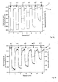
- Fig. 2a and 2b If one recognizes the reaction behavior of the sensor system 10 when changing the hydrogen concentration in an air mixture to which the gas sensor 10 is exposed.
- the signal at the photodetector 74 is read in mV and corresponds to the reflection of the functional layer 30.
- the gas sensor 10 is exposed alternately for three minutes to a hydrogen-argon mixture and synthetic air.
- Fig. 2a shows a series of measurements that begins with a zero phase, while the gas sensor 10 is exposed to synthetic air. The first zero phase is followed by a total of six measurement phases m1, m2, m3, m4, m5, m6. These last about three minutes each, as well as the zero phases between the measuring phases.
- a gas mixture with a hydrogen concentration of 4% is applied, in the second measurement phase m2 a gas mixture with a hydrogen concentration of 3%, in the third measurement phase m3 a gas mixture with a hydrogen concentration of 2%, in the fourth measurement phase m4 Gas mixture with a hydrogen concentration of 1%, in the fifth measurement phase m5 a gas mixture with a hydrogen concentration of 0.5% and in the sixth measurement phase Gas mixture with a hydrogen concentration of 0.25%.
- the gas sensor 10 is exposed to synthetic air without hydrogen in each case in a zero phase as already described above.
- the synthetic air is a mixture of approx.
- Fig. 2a shows on the abscissa the time course in minutes, on the left ordinate the voltage measured by the transistor in mV is readable, on the right ordinate the present hydrogen concentration in percent.
- the course of the measurement and zero phases can be recognized by the curve A, which represents the hydrogen concentration.
- Curve B shows the voltage change occurring at the photodetector 74 during the measurement and zero phases. It can be seen that a change in voltage is almost immediately accompanied by a change in the hydrogen concentration.
- the gas sensor 10 reacts immediately to the acting hydrogen in all measuring phases m1, m2, m3, m4, m5, m6 and has reached 90% of the saturation level in ⁇ 5 seconds. The desorption of the hydrogen during the zero phase at the end of the respective measurement phase m1, m2, m3, m4, m5, m6 takes place in ⁇ 5 seconds.
- the gas sensor 10 is characterized in a range between 0.25% and 4% hydrogen concentration by rapid and reliable display of the hydrogen.
- the gas sensor 10 is exposed to a gas mixture with 0.05% hydrogen concentration, in the second measurement phase m8 a gas mixture with 0.04% hydrogen concentration, in the third measurement phase m9 a gas mixture with 0.03% hydrogen concentration in the fourth Measurement phase m10 a gas mixture with 0.02% hydrogen concentration and in the fifth measurement phase m11 a gas mixture with 0.01% hydrogen concentration.
- the gas sensor 10 in a few seconds also reacts to small amounts of hydrogen, with the desorption in the zero phase after the end of the each measurement phase m7, m8, m9, m10, m11 takes place in ⁇ 30 seconds.
- Fig. 3 it can be seen that the gas sensor 10 under the action of hydrogen gas, so far in a transition of the functional layer 30 from the metallic state in the Hydride state by the occurring hydrogen absorption with a photodetector 74 resulting voltage change between about 100 and 900 mV.
- the voltage difference in mV occurring on the photodetector 74 and on the ordinate of the diagram the hydrogen concentration in the acting gas mixture is shown on the abscissa of the diagram.
- the voltage difference is also low at about 100 mV, and at a high hydrogen concentration of about 4%, the voltage difference at about 900 mV is also high.
- the voltage difference increases continuously with increasing hydrogen concentration.
- the aid of the gas sensor 10 it can not only be established in principle that hydrogen is present in a gas mixture, but it can also be estimated whether the proportion is rather low or already in the critical region near the lower explosion limit.
- Fig. 4a, 4b and 4c it can be seen that the response of the gas sensor 10 is of consistent quality over a large number of switching cycles. It shows Fig. 4b an example of a gas sensor of the prior art, Fig. 4a the long-term profile of a gas sensor 10 according to the invention over 200 switching cycles and Fig. 4c the long-term profile of a gas sensor 10 according to the invention over 1200 switching cycles.
- Fig. 4b It can be seen from the prior art that the amplitude of the voltage difference, measured at the photodetector 74, decreases already after a few switching cycles. In contrast, the voltage difference caused by the gas sensor 10 according to the invention when adding hydrogen in a gas mixture remains almost constant until the end of the measurements. In Fig. 4a one recognizes no reduction of the voltage difference. In Fig. 4c only a marginal change is visible.
- the gas sensor 10 according to the invention thus has a significantly longer stability and higher reliability than a gas sensor known from the prior art for comparison.
- Fig. 5a is the response of a gas sensor 10 immediately after deposition of the layers of the gas sensor 10 (curve A with square measuring points), after a long-term load test (curve B with round measuring points) and after a one-month storage time without intermediate circuit (curve C with triangular measuring points) shown.
- the abscissa represents the measuring time in seconds and the ordinate the voltage in mV.
- the line W marks the time from which the gas sensor 10 is exposed to a gas mixture containing a concentration of 4% hydrogen gas. Before this time, the functional layer 30 is in the metallic state.
- the functional layer 30 absorbs the hydrogen dissociated by the catalyst layer 50 and changes to the hydride state, which is due to a change in the Light reflection of the layer and subsequently by a voltage change at the photodetector 74, which detects the emitted light from the light source 73, can be seen.
- the gas sensor 10 is stored for one month after the long-term stress test, that is, it is not in contact with it during storage Hydrogen gas is brought, and then a switching operation is performed, which is shown in curve C.
- the voltage change is slightly stronger than after the long-term load. However, it takes much longer to reach saturation of 90% upon exposure to hydrogen gas, namely 1.75 s. The voltage difference is so far lower in curve A and B, so after a long-term load or a one-month storage time, but still sufficient to allow reliable detection of hydrogen in a gas mixture.
- Fig. 5b is the desorption of a gas sensor 10 immediately after deposition of the layers of the gas sensor 10 (curve A with square measurement points), after a long-term load test (curve B with round measurement points) and after a one-month storage time without intermediate circuit (curve C with triangular measurement points) shown.
- the measuring time in seconds is shown on the abscissa and the voltage at the photodetector 74 in mV on the ordinate.
- the line W marks the time up to which the gas sensor 10 is exposed to a gas mixture containing a 4% concentration of hydrogen.
- the functional layer 30 is in the hydride state. From this point on, the stored hydrogen desorbs from the functional layer 30. As a result, the functional layer 30 reverts to the metallic state, which in turn can be recognized by a change in the reflection of the layer and subsequently by a voltage change at the photodetector 74.
- the detected voltage difference between the hydride hydride state loaded with hydrogen and the metallic state without embedded hydrogen is also greatest in curve A.
- curve B the voltage difference is lower, i. in the metallic state, only a lower voltage level is achieved.
- curve C the voltage difference is about as high as in curve B.
- the photodetector 74, 74 ' is a phototransistor, in a second variant a photodiode, in a third variant a photoresistor and in a fourth variant a photomultiplier.
- the substrate layer 20 is in a first variant of float glass, in a second variant of a plastic e.g. Polycarbonate.
- the intermediate layer 40 can also consist of V or a mixture of Ti and V.
- this intermediate layer is additionally doped with Mg.
- the catalyst layer 50 is formed in a first alternative variant of Pd or a mixture of Pd and Pt.
- the cover layer 60 will also be made of a modified polytetrafluoroethylene as an alternative to polytetrate fluoroethylene.
- a gas sensor 10 for detecting hydrogen gas wherein the gas sensor 10 has at least one substrate layer 20, a functional layer 30 and a catalyst layer 50, the functional layer 30 being arranged between the substrate layer 20 and the catalyst layer 50
- the functional layer 30 being arranged between the substrate layer 20 and the catalyst layer 50
- an intermediate layer 40 is disposed and when a cover layer 60 is on the catalyst layer 50 and that the functional layer 30 is a magnesium titanium alloy.
- the intermediate layer 40 consists of a hydrogenatable metal, namely a transition metal, preferably of Ti or V, particularly preferably of Ti.
- the catalyst layer 50 consists of a metal which has a high hydrogen absorption capacity, namely of Pd or Pt, preferably of Pd.
- the cover layer 60 consists of polytetrafluoroethylene or a modified polytetrafluoroethylene.
- the substrate layer 20 is made of a material selected from the group consisting of glass, quartz glass, polycarbonate, sapphire, Si.
- the gas sensor 10 has electrodes 71, 72 and if the gas sensor 10 has at least one photodetector 74, 74 '.
- the hydrogen detector has a sensor unit, a calibration unit, an amplification unit and a display unit, wherein the gas sensor 10 is used as a sensor unit.
- a further advantage of the invention lies in a mobile hydrogen detector with a sensor unit, a calibration unit, an amplification unit and a display unit, wherein the sensor unit is a gas sensor 10 according to the invention.
Landscapes
- Chemical & Material Sciences (AREA)
- Life Sciences & Earth Sciences (AREA)
- Engineering & Computer Science (AREA)
- Health & Medical Sciences (AREA)
- Analytical Chemistry (AREA)
- Food Science & Technology (AREA)
- Medicinal Chemistry (AREA)
- Physics & Mathematics (AREA)
- Combustion & Propulsion (AREA)
- Biochemistry (AREA)
- General Health & Medical Sciences (AREA)
- General Physics & Mathematics (AREA)
- Immunology (AREA)
- Pathology (AREA)
- Investigating Or Analysing Materials By The Use Of Chemical Reactions (AREA)
- Investigating Or Analyzing Materials By The Use Of Fluid Adsorption Or Reactions (AREA)
Description
- Die Erfindung betrifft einen Gassensor zur Detektion von Wasserstoffgas gemäß dem Oberbegriff von Anspruch 1, die Verwendung eines solchen Gassensors in einem mobilen Wasserstoffdetektor nach Anspruch 8 und einen mobilen Wasserstoffdetektor gemäß Anspruch 10.
- Gassensoren zur Detektion von Wasserstoffgas werden unter anderem verwendet, um die Sicherheit von Wasserstofftanks zu kontrollieren. Dabei muss sichergestellt werden, dass die untere Explosionsgrenze von 4% Wasserstoff in Luft im Falle eines Austritts von Wasserstoffgas aus einem Tank auf keinen Fall überschritten wird.
- Im Stand der Technik sind eine Reihe solcher Sensoren bekannt, die zum Teil auf unterschiedlichen Messverfahren beruhen. So sind einerseits optische Sensoren bekannt, die eine Veränderung der Transmissivität feststellen, als auch elektrisch lesbare Sensoren, die eine Widerstandsänderung nachweisen. Eine wesentliche Anforderung an solche Wasserstoff-Sensoren ist, dass sie eine hohe Sensitivität, Selektivität und Stabilität aufweisen.
- Yoshimura et al. (K. Yoshimura, Y. Yamada, M. Okada, M. Tazawa and P. Jin: "Room-Temperature Hydrogen Sensor Based on Pd-Capped Mg2Ni Thin Films", Japanese Journal of Applied Physics, L507-L509) beschreiben beispielsweise einen elektrisch lesbaren Wasserstoff-Sensor, der aus einem Glassubstrat, einer funktionellen Mg2Ni-Schicht und einer Palladium-Schicht besteht. Die Palladium-Schicht dient dabei als Mittel zur Aktivierung oder Spaltung von Wasserstoff. Die Mg2Ni-Schicht wird zum Nachweis des aktivierten bzw. gespaltenen Wasserstoffs verwendet.
- Die Veröffentlichung von S. Bao, Y. Yamada, K. Tajima, M. Okada und K. Yoshimura in Solar Energy Materials & Solar Cells, 93, 2009, 1642-1646 ("Optical property and cycling durability of polytetrafluoroethylene top-covered and metal buffer layer inserted Mg-Ni switchable mirror") betrifft Schichten für schaltbare Spiegel, wobei eine schaltbare Dünnschicht aus seiner Mg/Ni-Legierung besteht. Diese schaltbaren Spiegel sind für Fenster-Anwendungen vorgesehen.
- Die
WO 2007/062629 A2 beschreibt einen Gassensor, der sowohl optisch als auch elektrisch auslesbar ist. Dieser Gassensor besteht aus einem Schichtsystem mit einer Substratschicht, einer funktionellen Schicht und einer Schicht zur Aktivierung oder Spaltung von Wasserstoff. Als Substratschicht wird ein transparentes Material wie z.B. Glas oder Kunststoff verwendet. Die Schicht zur Wasserstoffaktivierung bzw. -spaltung besteht aus Platin oder Palladium. Als funktionelle Schicht mit deren Hilfe der aktivierte bzw. gespaltene Wasserstoff nachweisbar ist, wird eine Legierung von Magnesium mit Nickel oder Aluminium verwendet. Die Magnesium-Aluminium-Legierungen können zusätzlich weitere Elemente aus der Gruppe Li, Be, Na, Ti, V, Cr, Mn, Fe, Co, Ni, Zr, Nb, Mo, Tc, Ru, Rh, Pd, Ag, Cd, Hf, Ta, W, Re, Os, Ir, Pt, Au, Hg, Si, K, Ca, Ga, Ge, As, Zn, Cu aufweisen. - Laufer (A. Laufer: "Neue Generation von Wasserstoffdetektoren basierend auf MagnesiumMetall-Verbindungen" Diplomarbeit an der Justus-Liebig-Universität Gießen 2007) offenbart die Verwendung von Mg-Fe-Legierungen als aktive Schicht in einem Sensor, der ebenfalls aus einer Substratschicht, einer funktionellen Schicht und einer Schicht zur Aktivierung von Wasserstoff besteht. Dieser Sensor ist für die Detektion von Wasserstoffgas-Konzentrationen < 1% in Luft geeignet. Sensorsysteme mit Mg-Fe-Legierungen weisen im Bereich von 1 -0,1% Wasserstoff die größte Signaländerung auf.
- Die Posterpräsentation DS 42.105 von M. K. Dietrich, G. Haas, A. Portz, A. Laufer, A. Polity und B. K. Meyer ("Optical switching properties and durability of a Mg-Fe alloy based thin film hydrogen sensor") am 16.03.2011 während der Veranstaltung "Verhandlungen der deutschen physikalischen Gesellschaft" in Dresden betrifft einen auf Mg-Fe basierenden Dünnschicht-Wasserstoffsensor, wobei dieser aus einer Funktionsschicht von MgFe, einer Zwischenschicht ("buffer layer") aus Titan, einer aus Pd bestehenden Katalysatorschicht und einer Deckschicht aus PTFE aufgebaut ist.
- Problematisch ist bei den oben genannten Lösungen häufig, dass die Ansprechzeiten der bisher bekannten Sensoren oft > 10 s betragen können. Darüber hinaus können die bekannten Wasserstoff-Sensoren ungünstige temperaturabhängige Funktionsbereiche aufweisen und einen hohen Energieverbrauch haben. Auch die mobile Einsatzfähigkeit ist nicht immer gegeben.
- Aufgabe der vorliegenden Erfindung ist es daher, einen verbesserten Gassensor zu Detektion von Wasserstoffgas bereit zustellen, der diese und andere Nachteile im Stand der Technik überwindet. Insbesondere soll ein Gassensor bereitgestellt werden, der eine möglichst schnelle Ansprechzeit, einen weitgehend temperaturunabhängigen Funktionsbereich und geringen Energieverbrauch aufweist. Der Gassensor soll außerdem möglichst mobil einsetzbar, robust und im Verhältnis preiswert herstellbar sein.
- Hauptmerkmale der Erfindung sind im kennzeichnenden Teil von Anspruch 1 angegeben. Ausgestaltungen sind Gegenstand der Ansprüche 2 bis 7 und 9, sowie der nebengeordneten Ansprüche 8 und 10.
- Bei einem Gassensor zur Detektion von Wasserstoffgas, wobei der Gassensor wenigstens eine Substratschicht, eine funktionelle Schicht und eine Deckschicht aufweist, wobei die funktionelle Schicht zwischen der Substratschicht und der Deckschicht angeordnet ist, sieht die Erfindung vor, dass zwischen der funktionellen Schicht und der Deckschicht eine Katalysatorschicht und eine Zwischenschicht angeordnet sind und dass die funktionelle Schicht eine Mg/Ti-Schicht ist.
- Besonders vorteilhaft sind bei einem so gestalteten Gassensor, die zwischen der funktionellen Mg/Ti-Schicht und der Deckschicht angeordneten Schichten. In der Katalysatorschicht kann sich der nachzuweisende Wasserstoff lösen. Das führt zur Dissoziation des Wasserstoffs. Der dissoziierte Wasserstoff kann aus der Katalysatorschicht in die Zwischenschicht übergehen und von dort in die funktionelle Schicht, die in dessen Gegenwart vom metallischen in den Hydridzustand übergeht. Die Zwischenschicht kann die funktionelle Schicht auf diese Weise vor Degradationseffekten schützen, die durch Volumenaufweitungen der Katalysatorschicht durch die Absorption des Wasserstoffs entstehen. Die funktionelle Schicht, die Zwischenschicht und die Katalysatorschicht können dabei derart zusammenwirken, dass einerseits eine sehr kurze Ansprechzeit auf das einwirkende Wasserstoffgas erreicht wird. Andererseits kann die funktionelle Schicht sehr schnell wieder vom Hydrid-Zustand in den metallischen Ausgangszustand zurück versetzt werden. Der erfindungsgemäße Sensor ist insofern von hoher Sensibilität und kann sehr selektiv Wasserstoff nachweisen. Gleichzeitig schützt die Deckschicht die empfindlichen darunter liegenden Schichten gegenüber nachteiligen Umwelteinflüssen.
- Die zwischen der Katalysatorschicht und der funktionellen Schicht angeordnete Zwischenschicht besteht aus einem hydrierbaren Metall. Bei einem solchen Metall handelt es sich um ein Übergangsmetall, wie Ti, V, V/Ti, Nb, Ta, Pt und Fe. Besonders günstig ist dabei die Verwendung der gut handhabbaren und in ausreichenden Mengen erhältlichen Metalle Ti oder V, insbesondere Ti. Die Zwischenschicht kann dabei zusätzlich als Schutz vor Oxidation für die darunter liegende Mg/Ti- Schicht dienen. Dadurch kann die Standzeit des erfindungsgemäßen Gassensors deutlich verbessert sein. Eine Sauerstoffvergiftung der funktionellen Schicht kann weitestgehend verhindert, zumindest aber deutlich verzögert werden.
- Die Katalysatorschicht besteht aus einem Metall, das eine hohe Wasserstoffadsorptionsfähigkeit aufweist. Bei einem solchen Metall handelt es sich um ein Platinoid, nämlich Pd oder Pt. Besonders günstig ist dabei die Verwendung des in relativ großen Mengen und im Verhältnis kostengünstig erhältlichen Metalls Pd. Dabei zeichnet sich vor allem Pd dadurch aus, dass es leicht und reaktionsfreudig ist. Die Katalysatorschicht besteht also aus Pd oder Pt, besonders bevorzugt aus Pd. Alternativ wird eine Pd-Pt-Legierung eingesetzt.
- Die Deckschicht kann beispielsweise aus Polytetrafluorethylen oder einem modifizierten Polytetrafluorethylen bestehen. Eine dünne gasdurchlässige Polytetrafluorethylen- (PTFE, Teflon) Schicht schützt so einerseits die Katalysatorschicht vor schädlichen Umwelteinflüssen, andererseits kann das Luftgemisch, das den nachzuweisenden Wasserstoff enthält, die Katalysatorschicht problemlos erreichen. Ein Beispiel für ein modifiziertes Polytetrafluorethylen ist sulfoniertes Polytetrafluorethylen (Nafion). Der Sensor weist somit eine deutlich verbesserte Stabilität gegen H2S auf.
- Im Sinne einer einfachen Ausführungsform ist es bei einem solchen Gassensor von Vorteil, dass die Substratschicht aus einem Material ausgewählt aus der Gruppe enthaltend Glas, Quarzglas, Polycarbonat, Saphir, Si besteht. Beispielsweise ist die Substratschicht aus Floatglas hergestellt.
- Eine besonders günstige Ausführungsvariante des erfindungsgemäßen Gassensors besteht insofern aus einer Substratschicht aus Glas, auf der eine Mg/Ti-Schicht als funktionelle Schicht gefolgt von einer Ti-Schicht als Zwischenschicht, einer Pd-Schicht als Katalysatorschicht und einer PTFE-Deckschicht aufgebracht sind.
- Die Mg/Ti-Schicht hat den Vorteil, dass sie ein besseres Schaltverhalten und eine bessere Stabilität ermöglicht. Sensorsysteme mit Mg/Ti als funktionale Schicht weisen eine größere Änderung der optischen Reflektivität beim Übergang vom metallischen in den Hydridzustand und schnellere Ansprechzeiten (<250ms) auf, sowie eine hohe Stabilität in Bezug auf das gleichbleibende Schaltungsverhalten unter Wasserstoffeinwirkung sowie eine hohe Stabilität in Bezug auf die Struktur der Schichten und der Schichtenabfolge im Messzustand.
- Bei einem Übergang zwischen dem metallischen und dem Hydridzustand ändert sich der elektrische Widerstand der funktionellen Schicht. Es ist daher günstig, wenn der Gassensor Elektroden aufweist. Diese können unterhalb der funktionellen Mg/Ti-Schicht ausgebildet sein. Mit ihrer Hilfe sind die Widerstandsänderungen der Mg/Ti-Schicht messbar. Dabei kann es sich beispielsweise um zwei schmale Goldstreifen handeln, die auf das Substrat aufgedampft sind. Die Goldstreifen werden dann durch die Mg/Ti-Schicht bedeckt, so dass sie zwischen dem Substrat und der funktionellen Schicht angeordnet sind.
- Daneben ändert sich bei einem Übergang vom metallischen Zustand in den Hydridzustand auch die Transmissivität (optische Transmission) der funktionellen Mg/Ti-Schicht. Eine optische Auswertung des jeweiligen Zustandes kann im einfachsten Fall visuell erfolgen. Vorteilhaft ist aber, wenn der Gassensor wenigstens einen Photodetektor aufweist. Dabei kann es sich beispielsweise um einen Photohalbleiter, etwa einen Photowiderstand, eine Photodiode oder einen Phototransistor, oder um einen Photomultiplier handeln. Der Gassensor ist dabei so gestaltet, dass eine künstliche Lichtquelle auf den Sensor einstrahlt. Der Photodetektor kann dann entweder auf der der Lichtquelle gegenüberliegenden Seite der Sensorschichten angeordnet sein und messen, welcher Lichtanteil die Sensorschichten durchdringt. Alternativ kann er auch in einem bestimmten Winkel zur Lichtquelle auf derselben Seite des Sensors angeordnet sein und messen, wie hoch der reflektierte Anteil des Lichtes ist.
- Die Erfindung sieht weiterhin die Verwendung eines erfindungsgemäßen Gassensors in einem mobilen Wasserstoffdetektor vor. Dabei ist es günstig, wenn der Wasserstoffdetektor eine Sensoreinheit, einen Kalibriereinheit, eine Verstärkungseinheit und eine Anzeigeeinheit aufweist, wobei der Gassensor als Sensoreinheit verwendet wird.
- Darüber hinaus sieht die Erfindung einen mobilen Wasserstoffdetektor mit einer Sensoreinheit, einem Kalibriereinheit, einer Verstärkungseinheit und einer Anzeigeeinheit vor, wobei die Sensoreinheit ein erfindungsgemäßer Gassensor ist.
- Weitere Merkmale, Einzelheiten und Vorteile der Erfindung ergeben sich aus dem Wortlaut der Ansprüche sowie aus der folgenden Beschreibung von Ausführungsbeispielen anhand der Zeichnungen. Es zeigen:
- Fig. 1a, 1b
- Schematischer Schichtaufbau eines erfindungsgemäßen Gassensors
- Fig. 2a
- Schaltverhalten eines erfindungsgemäßen Gassensors bei einer maximalen Wasserstoffkonzentration von 0,25 % bis 4%
- Fig. 2b
- Schaltverhalten eines erfindungsgemäßen Gassensors bei Wasserstoffkonzentrationen von 0,01 % bis 0,05 %
- Fig. 3
- Spannungsdifferenz am Photodetektor des Gassensors im Verhältnis zur Wasserstoffkonzentration
- Fig. 4a, b, c
- Langzeitbelastungstest eines erfindungsgemäßen Gassensors im Vergleich zu herkömmlichen Gassensoren
- Fig. 5a, b
- Ansprechzeit eines erfindungsgemäßen Gassensors
- In den
Figuren 1a und 1b erkennt man jeweils den schematischen Aufbau eines Gassensors 10 zur Detektion von Wasserstoff. Auf einer Substratschicht 20 ist eine funktionelle Schicht 30 aufgebracht. Diese ist bedeckt von einer Zwischenschicht 40, über der wiederum eine Katalysatorschicht 50 angeordnet ist. Über der Katalysatorschicht 50 ist eine Deckschicht 60 angeordnet. - In
Fig. 1a erkennt man außerdem, dass zwischen der Substratschicht 20 und der funktionellen Schicht 30 zwei Elektroden 71, 72 angeordnet sind. Diese Elektroden 71, 72 dienen zur Messung des Widerstandes der funktionellen Schicht 30. Der inFig. 1 a dargestellte Gassensor 10 ist daher elektrisch auswertbar. Gleichzeitig ist der Gassensor 10 auch optisch auswertbar. Strahlt das Tageslicht oder das umgebende Raumlicht nämlich auf den Gassensor 10, so wird es je nach Zustand der funktionellen Schicht 30 an dieser in einem mehr oder weniger großen Anteil reflektiert. Der nicht reflektierte Teil des Lichtes dringt durch die funktionelle Schicht 30 hindurch. Ist die funktionelle Schicht 30 im metallischen Zustand, so wird nahezu das komplette einfallende Licht reflektiert. Ist die funktionelle Schicht 30 im Hydridzustand, so wird das Licht nahezu vollständig transmittiert. Der Benutzer des Gassensors 10 kann insofern mit bloßem Auge erkennen, ob Wasserstoff in einem Gasgemisch vorliegt, in dem er feststellt, ob das einfallende Licht reflektiert wird oder nicht. - In
Fig. 1b ist oberhalb des Gassensors 10 eine Lichtquelle 73 angeordnet, die auf den Gassensor 10 strahlt. Ein Photodetektor 74, 74' ist entweder oberhalb oder unterhalb des Gassensors 10 angeordnet. Der oberhalb des Gassensors 10 angeordnete Photodetektor 74 misst den Anteil des an der funktionellen Schicht 30 reflektierten Lichtes. Der unterhalb des Gassensors 10 angeordnete Photodetektor 74' misst den Anteil des durch die funktionelle Schicht 30 transmittierten Lichtes. Der inFig. 1b dargestellte Gassensor 10 ist daher optisch auswertbar. - In einem weiteren (nicht dargestellten) Ausführungsbeispiel weist der in
Fig. 1 a gezeigte Gassensor 10 zusätzlich zu den Elektroden 71, 72 auch eine Lichtquelle 73 und einen oder mehrere Photodetektoren 74, 74' auf. In einer ersten Variante weist dieser Gassensor 10 zwei Photodetektoren 74, 74' auf, von denen einer oberhalb und einer unterhalb des Gassensors 10 angeordnet ist. Dieser Gassensor 10 erfasst sowohl das reflektierte als auch das transmittierte Licht. In einer zweiten Variante ist der Gassensor 10 nur mit einem Photodetektor 74, 74' ausgestattet, der entweder oberhalb oder unterhalb des Gassensors 10 angeordnet ist. In diesem Fall wird entweder das reflektierte oder das transmittierte Licht gemessen. Ein solcher Gassensor 10 ist sowohl elektrisch als auch optisch auswertbar. - Die Substratschicht 20 des dargestellten Gassensors 10 ist aus Glas. Die funktionelle Schicht 30 ist eine Mg/Ti-Legierung. Die Zwischenschicht 40 besteht aus Ti. Die Katalysatorschicht 50 besteht aus Pd. Die Deckschicht 60 ist aus Polytetrafluorethylen (Teflon).
- In den
Fig. 2a und 2b erkennt man das Reaktionsverhalten des Sensorsystems 10 bei Änderung der Wasserstoffkonzentration in einem Luftgemisch, dem der Gassensor 10 ausgesetzt ist. Das Signal am Photodetektor 74 wird in mV ausgelesen und entspricht der Reflektion der funktionalen Schicht 30. Der Gassensor 10 wird dabei abwechselnd für drei Minuten einem Wasserstoff-Argon-Gemisch und synthetischer Luft ausgesetzt.Fig. 2a zeigt dabei eine Messreihe, die mit einer Nullphase beginnt, dabei wird der Gassensor 10 synthetischer Luft ausgesetzt. Die erste Nullphase wird gefolgt von insgesamt sechs Messphasen m1, m2, m3, m4, m5, m6. Diese dauern jeweils etwa drei Minuten, ebenso wie die zwischen den Messphasen liegenden Nullphasen. In der ersten Messphase m1 wird ein Gasgemisch mit einer Wasserstoffkonzentration von 4 % angelegt, in der zweiten Messphase m2 ein Gasgemisch mit einer Wasserstoffkonzentration von 3 %, in der dritten Messphase m3 ein Gasgemisch mit einer Wasserstoffkonzentration von 2 %, in der vierten Messphase m4 ein Gasgemisch mit einer Wasserstoffkonzentration von 1 %, in der fünften Messphase m5 ein Gasgemisch mit einer Wasserstoffkonzentration von 0,5 % und in der sechsten Messphase ein Gasgemisch mit einer Wasserstoffkonzentration von 0,25 %. Zwischen den Messphasen m1, m2, m3, m4, m5, m6 wird der Gassensor 10 jeweils in einer Nullphase wie bereits oben beschrieben synthetischer Luft ohne Wasserstoff ausgesetzt. Bei der synthetischen Luft handelt es sich um eine auch als Spülgas bezeichnete Mischung von ca. 20 % Sauerstoff in Stickstoff. Das Diagramm inFig. 2a zeigt auf der Abszisse den Zeitverlauf in Minuten, auf der linken Ordinate ist die vom Transistor gemessene Spannung in mV ablesbar, auf der rechten Ordinate die vorliegende Wasserstoffkonzentration in Prozent. Der Verlauf der Mess- und Nullphasen kann anhand der Kurve A, die die Wasserstoffkonzentration darstellt, erkannt werden. Kurve B zeigt die während der Mess- und Nullphasen auftretende Spannungsänderung am Photodetektor 74. Man erkennt, dass nahezu unmittelbar mit Änderung der Wasserstoffkonzentration auch eine Spannungsänderung einhergeht. Der Gassensor 10 reagiert in allen Messphasen m1, m2, m3, m4, m5, m6 sofort auf den einwirkenden Wasserstoff und hat in < 5 Sekunden 90 % des Sättigungsniveaus erreicht. Auch die Desorption des Wasserstoffs während der Nullphase am Ende der jeweiligen Messphase m1, m2, m3, m4, m5, m6 erfolgt in < 5 Sekunden. - Man erkennt, dass sich der Gassensor 10 in einem Bereich zwischen 0,25 % und 4 % Wasserstoffkonzentration durch schnelle und zuverlässige Anzeige des Wasserstoffs auszeichnet.
- Gleiches gilt für einen Bereich zwischen 0,01 und 0,05 % Wasserstoffkonzentration, wie man in
Fig. 2b erkennt. Dort sind insgesamt fünf Messphasen m7, m8, m9, m10, m11 dargestellt, die jeweils drei Minuten dauern und wie im Beispiel, dargestellt inFig. 2A , durch ebenfalls drei Minuten andauernde Nullphasen, in denen der Gassensor 10 synthetischer Luft ausgesetzt ist, unterbrochen werden. In der ersten Messphase m7 wird der Gassensor 10 einem Gasgemisch mit 0,05 % Wasserstoffkonzentration ausgesetzt, in der zweiten Messphase m8 einem Gasgemisch mit 0,04% Wasserstoffkonzentration, in der dritten Messphase m9 einem Gasgemisch mit 0,03 % Wasserstoffkonzentration, in der vierten Messphase m10 einem Gasgemisch mit 0,02 % Wasserstoffkonzentration und in der fünften Messphase m11 einem Gasgemisch mit 0,01 % Wasserstoffkonzentration. Auch hier ist deutlich feststellbar, dass der Gassensor 10 in wenigen Sekunden (< 20 s auf ein Gasgemisch mit 0,05 % bis 0,03 % Wasserstoffkonzentration) auch auf geringe Mengen Wasserstoffs reagiert, wobei auch die Desorption in der Nullphase nach dem Ende der jeweiligen Messphase m7, m8, m9, m10, m11 in < 30 Sekunden vonstatten geht. - In
Fig. 3 erkennt man, dass der Gassensor 10 bei Einwirkung von Wasserstoffgas, insofern also bei einem Übergang der funktionellen Schicht 30 vom metallischen Zustand in den Hydridzustand durch die stattfindende Wasserstoffabsorption mit einer am Photodetektor 74 anfallenden Spannungsänderung zwischen etwa 100 und 900 mV reagiert. Dabei ist auf der Abszisse des Diagramms die am Photodetektor 74 anfallende Spannungsdifferenz in mV und auf der Ordinate des Diagramms die Wasserstoffkonzentration im einwirkenden Gasgemisch dargestellt. Bei einer relativ geringen Wasserstoffkonzentration von etwa 0,01 % ist auch die Spannungsdifferenz mit ungefähr 100 mV gering, bei einer hohen Wasserstoffkonzentration von etwa 4% ist die Spannungsdifferenz mit ungefähr 900 mV ebenfalls hoch. Zwischen diesen Werten steigt die Spannungsdifferenz kontinuierlich mit zunehmender Wasserstoffkonzentration an. Es kann insofern mit Hilfe des Gassensors 10 nicht nur prinzipiell festgestellt werden, dass Wasserstoff in einem Gasgemisch vorhanden ist, sondern es kann auch abgeschätzt werden, ob der Anteil eher gering oder bereits im kritischen Bereich nahe der unteren Explosionsgrenze ist. - In den
Fig. 4a, 4b und 4c erkennt man, dass die Reaktion des Gassensors 10 auch im Laufe einer hohen Anzahl von Schaltzyklen von gleichbleibender Qualität ist. Dabei zeigtFig. 4b ein Beispiel eines Gassensors aus dem Stand der Technik,Fig. 4a das Langzeitprofil eines erfindungsgemäßen Gassensors 10 über 200 Schaltzyklen undFig. 4c das Langzeitprofil eines erfindungsgemäßen Gassensors 10 über 1200 Schaltzyklen. In dem inFig. 4b dargestellten Beispiel aus dem Stand der Technik erkennt man, dass die Amplitude der Spannungsdifferenz, gemessen am Photodetektor 74, bereits nach wenigen Schaltzyklen abnimmt. Im Gegensatz dazu bleibt die Spannungsdifferenz die der erfindungsgemäße Gassensor 10 bei Hinzufügung von Wasserstoff in einem Gasgemisch hervorruft bis zum Ende der Messungen nahezu konstant. InFig. 4a erkennt man keine Verringerung der Spannungsdifferenz. InFig. 4c ist nur eine marginale Veränderung erkennbar. Der erfindungsgemäße Gassensor 10 weist insofern eine deutlich längere Stabilität und höhere Zuverlässigkeit auf als ein zum Vergleich gemessener aus dem Stand der Technik bekannter Gassensor. - In
Fig. 5a ist das Ansprechverhalten eines Gassensors 10 unmittelbar nach Deposition der Schichten des Gassensors 10 (Kurve A mit quadratischen Messpunkten), nach einem Langzeitbelastungstest (Kurve B mit runden Messpunkten) und nach einer einmonatigen Lagerungszeit ohne zwischenzeitliche Schaltung (Kurve C mit dreieckigen Messpunkten) dargestellt. Dabei ist auf der Abszisse die Messzeit in Sekunden dargestellt und auf der Ordinate die Spannung in mV. Die Linie W markiert den Zeitpunkt, ab dem der Gassensor 10 einem Gasgemisch ausgesetzt ist, das eine Konzentration von 4% Wasserstoffgas enthält. Vor diesem Zeitpunkt liegt die funktionelle Schicht 30 im metallischen Zustand vor. Ab diesem Zeitpunkt absorbiert die funktionelle Schicht 30 den durch die Katalysatorschicht 50 dissoziierten Wasserstoff und geht in den Hydridzustand über, was an einer Änderung der Lichtreflektion der Schicht und in der Folge durch eine Spannungsänderung am Photodetektor 74, der das von der Lichtquelle 73 ausgestrahlte Licht detektiert, erkennbar ist. - Man erkennt, dass die größte Spannungsdifferenz und die schnellste Ansprechzeit in Kurve A unmittelbar nach Deposition der Schichten des Gassensors 10 beobachtbar sind. Die Zeit, innerhalb derer der Gassensor 10 eine Wasserstoffsättigung von 90% erreicht - üblicherweise als t90 bezeichnet - beträgt hier 0,25 s. Nach einem Langzeitbelastungstest, welcher etwa 1000 aufeinanderfolgende Schaltzyklen innerhalb von einer Woche umfasst, ist, wie man in Kurve B erkennt, die Spannungsdifferenz, die der Gassensor 10 noch erreicht, etwas geringer als unmittelbar nach Deposition der Schichten. Die Zeit bis zum Erreichen einer 90%igen Sättigung (t90) ist mit 0,75 s etwas länger als in Kurve A. Der Gassensor 10 wird nach dem Langzeitbelastungstest für einen Monat gelagert, das heißt dass er während der Lagerung nicht in Kontakt mit Wasserstoffgas gebracht wird, und anschließend wird ein Schaltvorgang durchgeführt, welcher in Kurve C dargestellt ist. Die Spannungsänderung ist etwas stärker als nach der Langzeitbelastung. Es dauert jedoch deutlich länger bis bei Einwirkung von Wasserstoffgas eine Sättigung von 90% erreicht wird, nämlich 1,75 s. Die Spannungsdifferenz ist insofern bei Kurve A und B, also nach einer Langzeitbelastung bzw. einer einmonatigen Lagerungszeit, geringer, aber immer noch ausreichend, um einen zuverlässigen Nachweis von Wasserstoff in einem Gasgemisch zu ermöglichen.
- In
Fig. 5b ist das Desorptionsverhalten eines Gassensors 10 unmittelbar nach Deposition der Schichten des Gassensors 10 (Kurve A mit quadratischen Messpunkten), nach einem Langzeitbelastungstest (Kurve B mit runden Messpunkten) und nach einer einmonatigen Lagerungszeit ohne zwischenzeitliche Schaltung (Kurve C mit dreieckigen Messpunkten) dargestellt. Dabei ist auf der Abszisse die Messzeit in Sekunden dargestellt und auf der Ordinate die Spannung am Photodetektor 74 in mV. Die Linie W markiert den Zeitpunkt bis zu dem der Gassensor 10 einem Gasgemisch ausgesetzt ist, das eine 4%ige Konzentration an Wasserstoff enthält. Vor diesem Zeitpunkt liegt die funktionelle Schicht 30 im Hydridzustand vor. Ab diesem Zeitpunkt desorbiert der eingelagerte Wasserstoff aus der funktionellen Schicht 30. In der Folge geht die funktionelle Schicht 30 wieder in den metallischen Zustand über, was wiederum an einer Änderung der Reflektion der Schicht und in der Folge durch eine Spannungsänderung am Photodetektor 74 erkennbar ist. - Auch hier ist in Kurve A, also unmittelbar nach Deposition der den Gassensor 10 bildenden Schichten, die schnellste Reaktion zu beobachten. Die Reaktionszeit, innerhalb derer der Gassensor 10 10% des Endspannungssignals erreicht - üblicherweise als t10 bezeichnet - beträgt hier 4,5 s. Nach einem Langzeitbelastungstest ist die Reaktionszeit mit 6,5 s, wie in Kurve B erkennbar, nur etwas länger als in Kurve A. Am längsten dauert die Desorption nach einem einmonatigen Lagerintervall ohne zwischenzeitliche Schaltung, wie in Kurve C erkennbar. Dabei dauert es 17 s bis die maximale Desorption erreicht ist. Der erste Anstieg der Spannung erfolgt jedoch nur geringfügig langsamer als in den Kurven A und B. Erst gegen Ende des Anstiegs flacht die Kurve C ab, weshalb es zur längeren Reaktionszeit kommt. Es ist jedoch auch hier innerhalb von weniger als 10 s eine eindeutige Reaktion feststellbar.
- Auch die detektierte Spannungsdifferenz zwischen dem mit Wasserstoff beladenen Hydridzustand und dem metallischen Zustand ohne eingelagerten Wasserstoff ist in Kurve A am größten. In Kurve B ist die Spannungsdifferenz geringer, d.h. im metallischen Zustand wird nur ein geringeres Spannungsniveau erreicht. In Kurve C ist die Spannungsdifferenz etwa so hoch wie in Kurve B.
- Man erkennt insgesamt in den
Fig. 5a und 5b , dass das Beste, im Sinne vom schnellsten und deutlichsten Ansprechverhalten eines erfindungsgemäßen Gassensors 10, unmittelbar nach Deposition der den Gassensor 10 bildenden Schichten erreicht wird. Auch nach Langzeitbelastung oder nach einer gewissen Lagerperiode ist der erfindungsgemäße Gassensor 10 aber immer noch in der Lage, ausreichend schnell und zuverlässig das Vorhandensein von Wasserstoff in einem Gasgemisch anzuzeigen. - Die Erfindung ist nicht auf eine der vorbeschriebenen Ausführungsformen beschränkt, sondern in vielfältiger Weise abwandelbar.
- In einer ersten Variante ist der Photodetektor 74, 74' ein Phototransistor, in einer zweiten Variante eine Photodiode, in einer dritten Variante ein Photowiderstand und in einer vierten Variante ein Photomultiplier.
- Die Substratschicht 20 ist in einer ersten Variante aus Floatglas, in einer zweiten Variante aus einem Kunststoff z.B. Polycarbonat.
- Die Zwischenschicht 40 besteht in einer ersten Variante aus Ti. In einer zweiten Variante kann die Zwischenschicht 40 auch aus V oder einem Gemisch aus Ti und V bestehen. Alternativ wird diese Zwischenschicht zusätzlich mit Mg dotiert.
- Die Katalysatorschicht 50 wird in einer ersten alternativen Variante aus Pd oder einem Gemisch aus Pd und Pt gebildet.
- Die Deckschicht 60 wird alternativ zu Polytetratfluorethylen auch aus einem modifizierten Polytetrafluorethylen bestehen.
- Man erkennt, dass es bei einem Gassensor 10 zur Detektion von Wasserstoffgas, wobei der Gassensor 10 wenigstens eine Substratschicht 20, eine funktionelle Schicht 30 und eine Katalysatorschicht 50 aufweist, wobei die funktionelle Schicht 30 zwischen der Substratschicht 20 und der Katalysatorschicht 50 angeordnet ist, von Vorteil ist, wenn zwischen der funktionellen Schicht 30 und der Katalysatorschicht 50 eine Zwischenschicht 40 angeordnet ist und wenn sich eine Deckschicht 60 auf der Katalysatorschicht 50 befindet und dass die funktionelle Schicht 30 eine Magnesiumtitanlegierung ist.
- Die Zwischenschicht 40 besteht aus einem hydrierbaren Metall, nämlich aus einem Übergangsmetall, bevorzugt aus Ti oder V, besonders bevorzugt aus Ti. Die Katalysatorschicht 50 besteht aus einem Metall, das eine hohe Wasserstoffabsorptionsfähigkeit aufweist, nämlich aus Pd oder Pt, bevorzugt aus Pd. Weiterhin ist es günstig, wenn die Deckschicht 60 aus Polytetrafluorethylen oder einem modifizierten Polytetrafluorethylen besteht. Die Substratschicht 20 ist aus einem Material ausgewählt aus der Gruppe enthaltend Glas, Quarzglas, Polycarbonat, Saphir, Si.
- Man erkennt weiterhin, dass es günstig ist, wenn der Gassensor 10 Elektroden 71, 72 aufweist und wenn der Gassensor 10 wenigstens einen Photodetektor 74, 74' aufweist.
- Darüber hinaus stellt man den Vorteil fest, der in der Verwendung eines erfindungsgemäßen Gassensors 10 in einem mobilen Wasserstoffdetektor liegt. Dabei ist es sinnvoll, wenn der Wasserstoffdetektor eine Sensoreinheit, einen Kalibriereinheit, eine Verstärkungseinheit und eine Anzeigeeinheit aufweist, wobei der Gassensor 10 als Sensoreinheit verwendet wird.
- Ein weiterer Vorteil der Erfindung liegt insofern in einem mobilen Wasserstoffdetektor mit einer Sensoreinheit, einer Kalibriereinheit, einer Verstärkungseinheit und einer Anzeigeeinheit, wobei die Sensoreinheit ein erfindungsgemäßer Gassensor 10 ist.
-
- A
- Kurve
- B
- Kurve
- C
- Kurve
- m1, m2, m3, m4, m5, m6, m7,m8, m9, m10, m11
- Messphase
- 10
- Gassensor
- 20
- Substratschicht
- 30
- funktionelle Schicht
- 40
- Zwischenschicht
- 50
- Katalysatorschicht
- 60
- Deckschicht
- 71
- Elektrode
- 72
- Elektrode
- 73
- Lichtquelle
- 74
- Photodetektor
- 74'
- Photodetektor
Claims (10)
- Gassensor (10) zur Detektion von Wasserstoffgas, wobei der Gassensor (10) wenigstens eine Substratschicht (20), eine funktionelle Schicht (30) und eine Katalysatorschicht (50) aufweist, wobei die funktionelle Schicht (30) zwischen der Substratschicht (20) und der Katalysatorschicht (50) angeordnet ist, zwischen der funktionellen Schicht (30) und der Katalysatorschicht (50) eine Zwischenschicht (40) und auf der Katalysatorschicht (50) eine Deckschicht (60) angeordnet sind, die Zwischenschicht (40) aus einem hydrierbaren Metall, nämlich einem Übergangsmetall, besteht, dadurch gekennzeichnet, dass die Substratschicht (20) aus einem Material ausgewählt aus der Gruppe enthaltend Glas, Quarzglas, Polycarbonat, Saphir, Si besteht und die Katalysatorschicht (50) aus Pd, Pt oder einer Pd-Pt-Legierung besteht und die funktionelle Schicht (30) eine Mg/Ti-Schicht ist.
- Gassensor entsprechend Anspruch 1, dadurch gekennzeichnet, dass die Zwischenschicht (40) aus Ti oder V, bevorzugt aus Ti, besteht.
- Gassensor nach einem der Ansprüche 1 oder 2, dadurch gekennzeichnet, dass die Katalysatorschicht (50) eine hohe Wasserstoffabsorptionsfähigkeit aufweist.
- Gassensor nach einem der Ansprüche 1 bis 3, dadurch gekennzeichnet, dass die Katalysatorschicht (50) aus Pd besteht.
- Gassensor nach einem der Ansprüche 1 bis 4, dadurch gekennzeichnet, dass die Deckschicht (60) aus Polytetrafluorethylen oder einem modifizierten Polytetrafluorethylen besteht.
- Gassensor nach einem der Ansprüche 1 bis 5, dadurch gekennzeichnet, dass der Gassensor (10) Elektroden (71, 72) aufweist.
- Gassensor nach einem der Ansprüche 1 bis 6, dadurch gekennzeichnet, dass der Gassensor (10) wenigstens einen Photodetektor (74, 74') aufweist.
- Verwendung eines Gassensors (10) nach einem der Ansprüche 1 bis 7 in einem mobilen Wasserstoffdetektor.
- Verwendung nach Anspruch 8, dadurch gekennzeichnet, dass der Wasserstoffdetektor eine Sensoreinheit, eine Kalibriereinheit, eine Verstärkungseinheit und eine Anzeigeeinheit aufweist, wobei der Gassensor (10) als Sensoreinheit verwendet wird.
- Mobiler Wasserstoffdetektor mit einer Sensoreinheit, einer Kalibriereinheit, einer Verstärkungseinheit und einer Anzeigeeinheit, wobei die Sensoreinheit ein Gassensor (10) nach einem der Ansprüche 1 bis 7 ist.
Priority Applications (2)
| Application Number | Priority Date | Filing Date | Title |
|---|---|---|---|
| EP11189576.9A EP2594937B1 (de) | 2011-11-17 | 2011-11-17 | Gassensor zur Detektion von Wasserstoffgas |
| DE201210022330 DE102012022330A1 (de) | 2011-11-17 | 2012-11-15 | Gassensor zur Detektion von Wasserstoffgas |
Applications Claiming Priority (1)
| Application Number | Priority Date | Filing Date | Title |
|---|---|---|---|
| EP11189576.9A EP2594937B1 (de) | 2011-11-17 | 2011-11-17 | Gassensor zur Detektion von Wasserstoffgas |
Publications (2)
| Publication Number | Publication Date |
|---|---|
| EP2594937A1 EP2594937A1 (de) | 2013-05-22 |
| EP2594937B1 true EP2594937B1 (de) | 2015-07-22 |
Family
ID=45217228
Family Applications (1)
| Application Number | Title | Priority Date | Filing Date |
|---|---|---|---|
| EP11189576.9A Not-in-force EP2594937B1 (de) | 2011-11-17 | 2011-11-17 | Gassensor zur Detektion von Wasserstoffgas |
Country Status (2)
| Country | Link |
|---|---|
| EP (1) | EP2594937B1 (de) |
| DE (1) | DE102012022330A1 (de) |
Families Citing this family (3)
| Publication number | Priority date | Publication date | Assignee | Title |
|---|---|---|---|---|
| JP6709429B2 (ja) * | 2015-12-21 | 2020-06-17 | スタンレー電気株式会社 | 水素濃度測定装置 |
| DE102018200615A1 (de) * | 2018-01-16 | 2019-07-18 | Osram Gmbh | Verfahren zur Detektions eines Gases und Gasdetektionssystem |
| NL2026815B1 (en) * | 2020-11-03 | 2022-06-27 | Univ Delft Tech | (Optical) thin-film hydrogen sensing material based on tantalum or other group V element alloy |
Family Cites Families (1)
| Publication number | Priority date | Publication date | Assignee | Title |
|---|---|---|---|---|
| DE102005057214A1 (de) | 2005-11-29 | 2007-06-14 | Justus-Liebig-Universität Giessen | Erfindung betreffend Gassensoren |
-
2011
- 2011-11-17 EP EP11189576.9A patent/EP2594937B1/de not_active Not-in-force
-
2012
- 2012-11-15 DE DE201210022330 patent/DE102012022330A1/de not_active Withdrawn
Non-Patent Citations (1)
| Title |
|---|
| ANONYMOUS: "Duden | Platinoid | Rechtschreibung, Bedeutung, Definition, Herkunft", 2013, XP055126797, Retrieved from the Internet <URL:http://www.duden.de/rechtschreibung/Platinoid> [retrieved on 20140703] * |
Also Published As
| Publication number | Publication date |
|---|---|
| EP2594937A1 (de) | 2013-05-22 |
| DE102012022330A1 (de) | 2013-05-23 |
Similar Documents
| Publication | Publication Date | Title |
|---|---|---|
| DE69627093T2 (de) | Wasserstoffsensor | |
| DE69624885T2 (de) | Fühler für Kohlenstoffmonoxyd und toxische Gase mit Feuchtigkeitskompensation mit Hilfe von protonenleitenden Membranen und dessen Herstellungsverfahren | |
| EP2414822B1 (de) | Selektiver detektor für kohlenmonoxid | |
| DE69731454T2 (de) | Elektooptische schaltvorrichtung | |
| DE69422892T2 (de) | Verwendung von halbleitergassensoren | |
| DE69401347T2 (de) | Sensor | |
| EP3754329B1 (de) | Wasserstoffsensor und verfahren zu dessen herstellung, messvorrichtung und verfahren zum messen einer wasserstoffkonzentration | |
| Radeva et al. | Highly sensitive and selective visual hydrogen detectors based on YxMg1− x thin films | |
| WO2009074232A2 (de) | Gassensor mit einer verbesserten selektivität | |
| DE102008023482A1 (de) | Wasserstoffgas detektierende Membran | |
| EP2594937A1 (de) | Gassensor zur Detektion von Wasserstoffgas | |
| EP1955051B1 (de) | Wasserstoffsensor | |
| DE102013007872A1 (de) | Elektrochemischer Gassensor, Verfahren zu dessen Herstellung und dessen Verwendung | |
| DE69120948T2 (de) | Gasfühler | |
| DE102018206917B4 (de) | Vorrichtung und Verfahren zur Detektion von Gasen | |
| DE112020005838T5 (de) | Gasdetektionsverfahren und informationsverarbeitungsvorrichtung | |
| WO2002040972A1 (de) | Vorrichtung und verfahren zur optischen messung von konzentrationen eines stoffes | |
| EP0305961A2 (de) | Elektrochemische Messzelle mit einem sauren Elektrolyten | |
| EP2643690B1 (de) | Dioden-dünnschichtanordnung zur detektion von wasserstoff und verfahren zu ihrer herstellung sowie wasserstoffsensor | |
| DE19935180C2 (de) | Solarzellen-Sensoren, Verfahren zu ihrer Herstellung und ihrer Anwendung | |
| DE19808663C2 (de) | System zur Branderkennung und Betriebsverfahren für dieses System | |
| EP2010894B1 (de) | Wasserstoffsensor | |
| DE10208767C1 (de) | Meßanordnung und Verfahren zur Bestimmung der Permeabilität einer Schicht für eine korrodierende Substanz sowie Bauelemente mit dieser Meßanordnung | |
| Kirkbright et al. | Fluorescence characteristics of inorganic complexes in hydrochloric acid medium at liquid-nitrogen temperature | |
| EP1378747A2 (de) | Optischer Sensor |
Legal Events
| Date | Code | Title | Description |
|---|---|---|---|
| PUAI | Public reference made under article 153(3) epc to a published international application that has entered the european phase |
Free format text: ORIGINAL CODE: 0009012 |
|
| AK | Designated contracting states |
Kind code of ref document: A1 Designated state(s): AL AT BE BG CH CY CZ DE DK EE ES FI FR GB GR HR HU IE IS IT LI LT LU LV MC MK MT NL NO PL PT RO RS SE SI SK SM TR |
|
| AX | Request for extension of the european patent |
Extension state: BA ME |
|
| 17P | Request for examination filed |
Effective date: 20131122 |
|
| RBV | Designated contracting states (corrected) |
Designated state(s): AL AT BE BG CH CY CZ DE DK EE ES FI FR GB GR HR HU IE IS IT LI LT LU LV MC MK MT NL NO PL PT RO RS SE SI SK SM TR |
|
| 17Q | First examination report despatched |
Effective date: 20140109 |
|
| GRAP | Despatch of communication of intention to grant a patent |
Free format text: ORIGINAL CODE: EPIDOSNIGR1 |
|
| INTG | Intention to grant announced |
Effective date: 20150305 |
|
| GRAS | Grant fee paid |
Free format text: ORIGINAL CODE: EPIDOSNIGR3 |
|
| GRAA | (expected) grant |
Free format text: ORIGINAL CODE: 0009210 |
|
| AK | Designated contracting states |
Kind code of ref document: B1 Designated state(s): AL AT BE BG CH CY CZ DE DK EE ES FI FR GB GR HR HU IE IS IT LI LT LU LV MC MK MT NL NO PL PT RO RS SE SI SK SM TR |
|
| REG | Reference to a national code |
Ref country code: GB Ref legal event code: FG4D Free format text: NOT ENGLISH |
|
| REG | Reference to a national code |
Ref country code: CH Ref legal event code: EP |
|
| REG | Reference to a national code |
Ref country code: IE Ref legal event code: FG4D Free format text: LANGUAGE OF EP DOCUMENT: GERMAN |
|
| REG | Reference to a national code |
Ref country code: AT Ref legal event code: REF Ref document number: 738190 Country of ref document: AT Kind code of ref document: T Effective date: 20150815 |
|
| REG | Reference to a national code |
Ref country code: DE Ref legal event code: R096 Ref document number: 502011007372 Country of ref document: DE |
|
| REG | Reference to a national code |
Ref country code: FR Ref legal event code: PLFP Year of fee payment: 5 |
|
| REG | Reference to a national code |
Ref country code: LT Ref legal event code: MG4D |
|
| REG | Reference to a national code |
Ref country code: NL Ref legal event code: MP Effective date: 20150722 |
|
| PG25 | Lapsed in a contracting state [announced via postgrant information from national office to epo] |
Ref country code: LV Free format text: LAPSE BECAUSE OF FAILURE TO SUBMIT A TRANSLATION OF THE DESCRIPTION OR TO PAY THE FEE WITHIN THE PRESCRIBED TIME-LIMIT Effective date: 20150722 Ref country code: LT Free format text: LAPSE BECAUSE OF FAILURE TO SUBMIT A TRANSLATION OF THE DESCRIPTION OR TO PAY THE FEE WITHIN THE PRESCRIBED TIME-LIMIT Effective date: 20150722 Ref country code: FI Free format text: LAPSE BECAUSE OF FAILURE TO SUBMIT A TRANSLATION OF THE DESCRIPTION OR TO PAY THE FEE WITHIN THE PRESCRIBED TIME-LIMIT Effective date: 20150722 Ref country code: GR Free format text: LAPSE BECAUSE OF FAILURE TO SUBMIT A TRANSLATION OF THE DESCRIPTION OR TO PAY THE FEE WITHIN THE PRESCRIBED TIME-LIMIT Effective date: 20151023 Ref country code: NO Free format text: LAPSE BECAUSE OF FAILURE TO SUBMIT A TRANSLATION OF THE DESCRIPTION OR TO PAY THE FEE WITHIN THE PRESCRIBED TIME-LIMIT Effective date: 20151022 |
|
| PG25 | Lapsed in a contracting state [announced via postgrant information from national office to epo] |
Ref country code: HR Free format text: LAPSE BECAUSE OF FAILURE TO SUBMIT A TRANSLATION OF THE DESCRIPTION OR TO PAY THE FEE WITHIN THE PRESCRIBED TIME-LIMIT Effective date: 20150722 Ref country code: PT Free format text: LAPSE BECAUSE OF FAILURE TO SUBMIT A TRANSLATION OF THE DESCRIPTION OR TO PAY THE FEE WITHIN THE PRESCRIBED TIME-LIMIT Effective date: 20151123 Ref country code: RS Free format text: LAPSE BECAUSE OF FAILURE TO SUBMIT A TRANSLATION OF THE DESCRIPTION OR TO PAY THE FEE WITHIN THE PRESCRIBED TIME-LIMIT Effective date: 20150722 Ref country code: ES Free format text: LAPSE BECAUSE OF FAILURE TO SUBMIT A TRANSLATION OF THE DESCRIPTION OR TO PAY THE FEE WITHIN THE PRESCRIBED TIME-LIMIT Effective date: 20150722 Ref country code: IS Free format text: LAPSE BECAUSE OF FAILURE TO SUBMIT A TRANSLATION OF THE DESCRIPTION OR TO PAY THE FEE WITHIN THE PRESCRIBED TIME-LIMIT Effective date: 20151122 Ref country code: PL Free format text: LAPSE BECAUSE OF FAILURE TO SUBMIT A TRANSLATION OF THE DESCRIPTION OR TO PAY THE FEE WITHIN THE PRESCRIBED TIME-LIMIT Effective date: 20150722 Ref country code: SE Free format text: LAPSE BECAUSE OF FAILURE TO SUBMIT A TRANSLATION OF THE DESCRIPTION OR TO PAY THE FEE WITHIN THE PRESCRIBED TIME-LIMIT Effective date: 20150722 |
|
| REG | Reference to a national code |
Ref country code: DE Ref legal event code: R097 Ref document number: 502011007372 Country of ref document: DE |
|
| PG25 | Lapsed in a contracting state [announced via postgrant information from national office to epo] |
Ref country code: CZ Free format text: LAPSE BECAUSE OF FAILURE TO SUBMIT A TRANSLATION OF THE DESCRIPTION OR TO PAY THE FEE WITHIN THE PRESCRIBED TIME-LIMIT Effective date: 20150722 Ref country code: IT Free format text: LAPSE BECAUSE OF FAILURE TO SUBMIT A TRANSLATION OF THE DESCRIPTION OR TO PAY THE FEE WITHIN THE PRESCRIBED TIME-LIMIT Effective date: 20150722 Ref country code: SK Free format text: LAPSE BECAUSE OF FAILURE TO SUBMIT A TRANSLATION OF THE DESCRIPTION OR TO PAY THE FEE WITHIN THE PRESCRIBED TIME-LIMIT Effective date: 20150722 Ref country code: DK Free format text: LAPSE BECAUSE OF FAILURE TO SUBMIT A TRANSLATION OF THE DESCRIPTION OR TO PAY THE FEE WITHIN THE PRESCRIBED TIME-LIMIT Effective date: 20150722 Ref country code: EE Free format text: LAPSE BECAUSE OF FAILURE TO SUBMIT A TRANSLATION OF THE DESCRIPTION OR TO PAY THE FEE WITHIN THE PRESCRIBED TIME-LIMIT Effective date: 20150722 |
|
| PLBE | No opposition filed within time limit |
Free format text: ORIGINAL CODE: 0009261 |
|
| STAA | Information on the status of an ep patent application or granted ep patent |
Free format text: STATUS: NO OPPOSITION FILED WITHIN TIME LIMIT |
|
| PG25 | Lapsed in a contracting state [announced via postgrant information from national office to epo] |
Ref country code: RO Free format text: LAPSE BECAUSE OF FAILURE TO SUBMIT A TRANSLATION OF THE DESCRIPTION OR TO PAY THE FEE WITHIN THE PRESCRIBED TIME-LIMIT Effective date: 20150722 |
|
| 26N | No opposition filed |
Effective date: 20160425 |
|
| PG25 | Lapsed in a contracting state [announced via postgrant information from national office to epo] |
Ref country code: MC Free format text: LAPSE BECAUSE OF FAILURE TO SUBMIT A TRANSLATION OF THE DESCRIPTION OR TO PAY THE FEE WITHIN THE PRESCRIBED TIME-LIMIT Effective date: 20150722 Ref country code: LU Free format text: LAPSE BECAUSE OF FAILURE TO SUBMIT A TRANSLATION OF THE DESCRIPTION OR TO PAY THE FEE WITHIN THE PRESCRIBED TIME-LIMIT Effective date: 20151117 |
|
| REG | Reference to a national code |
Ref country code: CH Ref legal event code: PL |
|
| PG25 | Lapsed in a contracting state [announced via postgrant information from national office to epo] |
Ref country code: LI Free format text: LAPSE BECAUSE OF NON-PAYMENT OF DUE FEES Effective date: 20151130 Ref country code: CH Free format text: LAPSE BECAUSE OF NON-PAYMENT OF DUE FEES Effective date: 20151130 |
|
| REG | Reference to a national code |
Ref country code: IE Ref legal event code: MM4A |
|
| PG25 | Lapsed in a contracting state [announced via postgrant information from national office to epo] |
Ref country code: SI Free format text: LAPSE BECAUSE OF FAILURE TO SUBMIT A TRANSLATION OF THE DESCRIPTION OR TO PAY THE FEE WITHIN THE PRESCRIBED TIME-LIMIT Effective date: 20150722 |
|
| PG25 | Lapsed in a contracting state [announced via postgrant information from national office to epo] |
Ref country code: IE Free format text: LAPSE BECAUSE OF NON-PAYMENT OF DUE FEES Effective date: 20151117 |
|
| REG | Reference to a national code |
Ref country code: FR Ref legal event code: PLFP Year of fee payment: 6 |
|
| PG25 | Lapsed in a contracting state [announced via postgrant information from national office to epo] |
Ref country code: HU Free format text: LAPSE BECAUSE OF FAILURE TO SUBMIT A TRANSLATION OF THE DESCRIPTION OR TO PAY THE FEE WITHIN THE PRESCRIBED TIME-LIMIT; INVALID AB INITIO Effective date: 20111117 Ref country code: SM Free format text: LAPSE BECAUSE OF FAILURE TO SUBMIT A TRANSLATION OF THE DESCRIPTION OR TO PAY THE FEE WITHIN THE PRESCRIBED TIME-LIMIT Effective date: 20150722 Ref country code: BG Free format text: LAPSE BECAUSE OF FAILURE TO SUBMIT A TRANSLATION OF THE DESCRIPTION OR TO PAY THE FEE WITHIN THE PRESCRIBED TIME-LIMIT Effective date: 20150722 |
|
| PG25 | Lapsed in a contracting state [announced via postgrant information from national office to epo] |
Ref country code: CY Free format text: LAPSE BECAUSE OF FAILURE TO SUBMIT A TRANSLATION OF THE DESCRIPTION OR TO PAY THE FEE WITHIN THE PRESCRIBED TIME-LIMIT Effective date: 20150722 Ref country code: NL Free format text: LAPSE BECAUSE OF FAILURE TO SUBMIT A TRANSLATION OF THE DESCRIPTION OR TO PAY THE FEE WITHIN THE PRESCRIBED TIME-LIMIT Effective date: 20150722 |
|
| PG25 | Lapsed in a contracting state [announced via postgrant information from national office to epo] |
Ref country code: BE Free format text: LAPSE BECAUSE OF NON-PAYMENT OF DUE FEES Effective date: 20151130 |
|
| PG25 | Lapsed in a contracting state [announced via postgrant information from national office to epo] |
Ref country code: MT Free format text: LAPSE BECAUSE OF FAILURE TO SUBMIT A TRANSLATION OF THE DESCRIPTION OR TO PAY THE FEE WITHIN THE PRESCRIBED TIME-LIMIT Effective date: 20150722 |
|
| REG | Reference to a national code |
Ref country code: FR Ref legal event code: PLFP Year of fee payment: 7 |
|
| REG | Reference to a national code |
Ref country code: AT Ref legal event code: MM01 Ref document number: 738190 Country of ref document: AT Kind code of ref document: T Effective date: 20161117 |
|
| PG25 | Lapsed in a contracting state [announced via postgrant information from national office to epo] |
Ref country code: AT Free format text: LAPSE BECAUSE OF NON-PAYMENT OF DUE FEES Effective date: 20161117 |
|
| PG25 | Lapsed in a contracting state [announced via postgrant information from national office to epo] |
Ref country code: TR Free format text: LAPSE BECAUSE OF FAILURE TO SUBMIT A TRANSLATION OF THE DESCRIPTION OR TO PAY THE FEE WITHIN THE PRESCRIBED TIME-LIMIT Effective date: 20150722 Ref country code: MK Free format text: LAPSE BECAUSE OF FAILURE TO SUBMIT A TRANSLATION OF THE DESCRIPTION OR TO PAY THE FEE WITHIN THE PRESCRIBED TIME-LIMIT Effective date: 20150722 |
|
| PG25 | Lapsed in a contracting state [announced via postgrant information from national office to epo] |
Ref country code: AL Free format text: LAPSE BECAUSE OF FAILURE TO SUBMIT A TRANSLATION OF THE DESCRIPTION OR TO PAY THE FEE WITHIN THE PRESCRIBED TIME-LIMIT Effective date: 20150722 |
|
| PGFP | Annual fee paid to national office [announced via postgrant information from national office to epo] |
Ref country code: DE Payment date: 20181120 Year of fee payment: 8 |
|
| PGFP | Annual fee paid to national office [announced via postgrant information from national office to epo] |
Ref country code: FR Payment date: 20181123 Year of fee payment: 8 Ref country code: GB Payment date: 20181120 Year of fee payment: 8 |
|
| REG | Reference to a national code |
Ref country code: DE Ref legal event code: R119 Ref document number: 502011007372 Country of ref document: DE |
|
| GBPC | Gb: european patent ceased through non-payment of renewal fee |
Effective date: 20191117 |
|
| PG25 | Lapsed in a contracting state [announced via postgrant information from national office to epo] |
Ref country code: FR Free format text: LAPSE BECAUSE OF NON-PAYMENT OF DUE FEES Effective date: 20191130 Ref country code: DE Free format text: LAPSE BECAUSE OF NON-PAYMENT OF DUE FEES Effective date: 20200603 Ref country code: GB Free format text: LAPSE BECAUSE OF NON-PAYMENT OF DUE FEES Effective date: 20191117 |