EP2594934B1 - Non-destructive inspection apparatus having an ergonomic grip and associated method - Google Patents
Non-destructive inspection apparatus having an ergonomic grip and associated method Download PDFInfo
- Publication number
- EP2594934B1 EP2594934B1 EP12192219.9A EP12192219A EP2594934B1 EP 2594934 B1 EP2594934 B1 EP 2594934B1 EP 12192219 A EP12192219 A EP 12192219A EP 2594934 B1 EP2594934 B1 EP 2594934B1
- Authority
- EP
- European Patent Office
- Prior art keywords
- workpiece
- grip
- destructive inspection
- ultrasonic sensor
- operator
- Prior art date
- Legal status (The legal status is an assumption and is not a legal conclusion. Google has not performed a legal analysis and makes no representation as to the accuracy of the status listed.)
- Active
Links
Images

Classifications
-
- G—PHYSICS
- G01—MEASURING; TESTING
- G01N—INVESTIGATING OR ANALYSING MATERIALS BY DETERMINING THEIR CHEMICAL OR PHYSICAL PROPERTIES
- G01N29/00—Investigating or analysing materials by the use of ultrasonic, sonic or infrasonic waves; Visualisation of the interior of objects by transmitting ultrasonic or sonic waves through the object
- G01N29/22—Details, e.g. general constructional or apparatus details
- G01N29/225—Supports, positioning or alignment in moving situation
- G01N29/226—Handheld or portable devices
-
- G—PHYSICS
- G01—MEASURING; TESTING
- G01N—INVESTIGATING OR ANALYSING MATERIALS BY DETERMINING THEIR CHEMICAL OR PHYSICAL PROPERTIES
- G01N29/00—Investigating or analysing materials by the use of ultrasonic, sonic or infrasonic waves; Visualisation of the interior of objects by transmitting ultrasonic or sonic waves through the object
- G01N29/04—Analysing solids
-
- G—PHYSICS
- G01—MEASURING; TESTING
- G01N—INVESTIGATING OR ANALYSING MATERIALS BY DETERMINING THEIR CHEMICAL OR PHYSICAL PROPERTIES
- G01N29/00—Investigating or analysing materials by the use of ultrasonic, sonic or infrasonic waves; Visualisation of the interior of objects by transmitting ultrasonic or sonic waves through the object
- G01N29/22—Details, e.g. general constructional or apparatus details
- G01N29/26—Arrangements for orientation or scanning by relative movement of the head and the sensor
- G01N29/265—Arrangements for orientation or scanning by relative movement of the head and the sensor by moving the sensor relative to a stationary material
-
- A—HUMAN NECESSITIES
- A61—MEDICAL OR VETERINARY SCIENCE; HYGIENE
- A61B—DIAGNOSIS; SURGERY; IDENTIFICATION
- A61B8/00—Diagnosis using ultrasonic, sonic or infrasonic waves
- A61B8/42—Details of probe positioning or probe attachment to the patient
- A61B8/4272—Details of probe positioning or probe attachment to the patient involving the acoustic interface between the transducer and the tissue
- A61B8/4281—Details of probe positioning or probe attachment to the patient involving the acoustic interface between the transducer and the tissue characterised by sound-transmitting media or devices for coupling the transducer to the tissue
-
- A—HUMAN NECESSITIES
- A61—MEDICAL OR VETERINARY SCIENCE; HYGIENE
- A61B—DIAGNOSIS; SURGERY; IDENTIFICATION
- A61B8/00—Diagnosis using ultrasonic, sonic or infrasonic waves
- A61B8/44—Constructional features of the ultrasonic, sonic or infrasonic diagnostic device
- A61B8/4444—Constructional features of the ultrasonic, sonic or infrasonic diagnostic device related to the probe
- A61B8/4455—Features of the external shape of the probe, e.g. ergonomic aspects
-
- G—PHYSICS
- G01—MEASURING; TESTING
- G01N—INVESTIGATING OR ANALYSING MATERIALS BY DETERMINING THEIR CHEMICAL OR PHYSICAL PROPERTIES
- G01N2291/00—Indexing codes associated with group G01N29/00
- G01N2291/04—Wave modes and trajectories
- G01N2291/044—Internal reflections (echoes), e.g. on walls or defects
Definitions
- An example embodiment of the present disclosure relates generally to a non-destructive inspection apparatus and associated method and, more particularly, to a non-destructive inspection apparatus having an ergonomic grip and an associated method.
- a variety of workpieces are subjected to non-destructive inspection in order to determine various characteristics of the workpiece.
- various structural panels such as wings, fuselage sections and the like, may be subjected to non-destructive inspection.
- a non-destructive inspection apparatus generally includes a sensor that is configured to emit signals into the workpiece and to receive return signals in response to the signals emitted by the sensor.
- the sensor of a non-destructive inspection apparatus may be, for example, an ultrasonic sensor configured to emit and to receive ultrasonic signals.
- a sensor may be positioned upon a workpiece.
- the sensor may then be actuated so as to emit signals into the workpiece and to receive return signals from the workpiece in response to the signals emitted by the sensor.
- various characteristics of the workpiece may be determined including, for example, the thickness of the workpiece and/or any anomalies that may exist within the portion of the workpiece that is being interrogated.
- Some non-destructive inspection apparatuses include a sensor that is manually placed upon the workpiece and then manually repositioned across the workpiece in order to interrogate a substantial portion of the workpiece.
- an operator must generally grasp the sensor and then repeatedly reposition the sensor at a number of positions across a workpiece.
- the operator may also exert a force intended to press the sensor against the surface of the workpiece.
- the placement and movement of a sensor generally requires some exertion on the part of the operator. The effort expended by the operator is generally compounded by the relatively small size of the sensor.
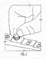
- an ultrasonic sensor 10 is generally quite small, such as smaller than one of the operator's fingers. As a result, an operator may find the sensor somewhat difficult to grasp and, more particularly, may find it challenging to not only grasp the sensor but to apply the force necessary to urge the sensor into contact with the underlying workpiece.
- the challenges that an operator faces in terms of grasping the sensor and applying the desired force to the workpiece may sometimes be compounded by the repetitive motion incurred as the operator places the sensor upon and moves the sensor across a workpiece. Additionally, the operator may be forced to assume a relatively uncomfortable pose while handling the inspection device since the workpiece may be relatively large and may require the operator to reach across at least a portion of the workpiece in order to properly place the sensor and to interrogate the corresponding portion of the workpiece.
- EP 1 935 343 A1 according to its abstract states: Ergonomic housing for electroacoustic transducers, particularly for ultrasound imaging, comprising at least an inner space housing one or more electroacoustic transducers and possible further electric and/or electronic components, which housing has at least an acoustic window at which the one or more electroacoustic transducers are placed and at least an handle part composed of an opposing gripping surface having a shape that is ergonomically fitted for being gripped by an hand or a part thereof, characterized in that the gripping surface has such a shape or profile to be ergonomically fitted for being gripped by inserting it in the hollow between two adjacent fingers of the hand, i.e. by holding it between the fingers.
- the invention relates also to a probe with a housing of said type and an ultrasound machine in combination.
- a palmar surface may allow for ease of gripping an ultrasound transducer probe. By facing the palmar surface so that the users hand is directed downwards, towards the patient's skin, during use, less wrist flexing may result.
- the cable extends from the transducer at a location other than the top of the transducer. Elastomer or other soft materials increase grip.
- a hand-held transducer probe is overlapped with elastomeric material for improving the friction and softness of the grip of the probe.
- the elastomeric material comprises a biocompatible material having a tear strength in excess of pounds per inch and a hardness level less than approximately shore A 80.
- a method of producing a hand-held transducer probe having an improved grip comprising the steps of assembling an acoustic array and cable assembly; attaching a handle portion over aid acoustic array and cable assembly; and attaching an elastomeric material over at least a portion of said handle portion.
- An ultrasonic inspection apparatus includes an ultrasonic probe including an ultrasonic transducer, a position detection device, a drive element selector which is connected to the plurality of piezoelectric elements of the ultrasonic transducer provided so as to select a required piezoelectric element, a signal detection circuit which allows the piezoelectric element selected by the drive element selector to transmit ultrasonic wave to an inspection object through an acoustic transmission medium, which receives reflection echo thereof, and which detects an electric signal of the reflection echo through, a signal processor which generates three-dimensional imaging data inside of the inspection object by processing the electric signal of the detected reflection echo, a position converting circuit which outputs an imaging-start trigger signal to a signal generator in response to a position detection signal, and a display device which displays an imaging result.
- a non-destructive inspection system is defined in claim 1.
- a method for non-destructively inspecting a workpiece according to the present disclosure is defined in claim 6.
- the non-destructive inspection system 20 includes a non-destructive inspection apparatus 22 including a sensor that is placed in operable contact with a workpiece 24 in order to interrogate the workpiece and to provide information from which one or more characteristics of the workpiece may be determined.
- the non-destructive inspection apparatus 22 may be configured to be manually positioned upon the workpiece 24 and to then be manually moved across the workpiece so as to interrogate the workpiece at each of a plurality of different positions.
- the non-destructive inspection apparatus 22 may be configured to be initially placed at a predetermined position upon the workpiece 24 and to thereafter be moved in a predefined pattern across a workpiece so as to interrogate the workpiece at each of a plurality of predefined positions.
- Various types of workpieces 24 may be subjected to non-destructive inspection.
- at least a portion of a wing is subjected to non-destructive inspection.
- a number of other types of workpieces 24 may be subjected to non-destructive inspection including other components of an aircraft or other vehicle, structural components of buildings or other structures and the like.
- the workpiece 24 to be inspected may be a composite structure.
- the workpiece 24 to be inspected may alternatively be constructed in other fashions.
- the non-destructive inspection system may include a couplant that is applied to at least a portion of the workpiece that is to be inspected such that the non-destructive inspection apparatus and, at least the sensor of the non-destructive inspection apparatus, is spaced from the surface of the workpiece by the couplant
- the couplant may be configured to facilitate coupling between the sensor and the workpiece 24, thereby increasing the efficiency with which the signals emitted by the sensor propagate into the workpiece 24 and the return signals from the workpiece propagate to the sensor.
- suitable couplants include ultrasonic gels and water.
- the non-destructive inspection system 20 may include a computer 26 as shown in Figure 2 .
- the non-destructive inspection system 20 may include various types of computer 26 including, without limitation, personal computers, laptop computers, tablet computers and mobile devices including mobile phones, personal digital assistants (PDAs) and the like.
- the computer 26 is in communication with the non-destructive inspection apparatus 22. While the non-destructive inspection apparatus 22 and the computer 26 may be configured to communicate with one another wirelessly, the non-destructive inspection apparatus and the computer may be configured for wired communication in other embodiments.
- the computer 26 may be configured to receive information from the non-destructive inspection apparatus 22 and to process, display and/or store the information in order to facilitate the inspection of the workpiece 24.
- the workpiece 24 may be inspected so as to identify various different characteristics of the workpiece.
- the non-destructive inspection apparatus 22 may inspect the workpiece 24 so as to determine the thickness of the workpiece.
- the non-destructive inspection apparatus 22 may emit signals into the workpiece 24 and may detect return signals that have reflected from an opposed surface of the workpiece such that the thickness of the workpiece may be determined based upon the elapsed time between the emission of the signals into the workpiece and the receipt of the return signals.
- the non-destructive inspection apparatus 22 may be configured to detect anomalies within the workpiece 24 by emitting signals into the workpiece and receiving return signals that are indicative of the presence or absence of an anomaly within the portion of the workpiece being interrogated.
- the non-destructive inspection apparatus 22 may include an ultrasonic sensor 28, such as an ultrasonic transducer, configured to be placed in operable contact with the workpiece 24.
- the ultrasonic sensor 28 may be placed in direct contact with the workpiece 24 or may be spaced apart from the workpiece by a couplant.
- the ultrasonic sensor 28 of this embodiment is configured to emit ultrasonic signals into the workpiece 24 and to receive return signals in response to the ultrasonic signals emitted thereby.
- the ultrasonic sensor 28 of the illustrated embodiment may be embodied as a transducer that is configured to both emit ultrasonic signals and to receive return signals
- the ultrasonic sensor may, in other embodiments, be embodied by an ultrasonic transmitter that is configured to emit ultrasonic signals into the workpiece 24 and a distinct or separate ultrasonic receiver that is configured to receive the return signal from the workpiece in response to the ultrasonic signals emitted by the ultrasonic transmitter.
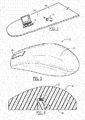
- the non-destructive inspection apparatus 22 of the illustrated embodiment also includes a grip 30 that is operably connected to the ultrasonic sensor 28.
- the grip 30 may be directly connected to the ultrasonic sensor.
- the ultrasonic sensor 28 may be embedded within the grip 30 so as to be exposed through and positioned proximate to the surface 32 of the grip that is placed in operable contact with the workpiece 24.
- the grip 30 of this embodiment may define a cavity in which the inspection sensor 28 is disposed and frictionally engaged.
- the grip 30 may be connected to the ultrasonic sensor 28 in other manners so that, for example, the ultrasonic sensor is external to the grip.
- the grip 30 and the ultrasonic sensor 28 are operably connected so that both the grip and the ultrasonic sensor are movable in concert. As such, movement of the grip 30 relative to the workpiece 24 causes the ultrasonic sensor 28 to move in a corresponding fashion.
- the grip 30 of the non-destructive inspection apparatus 22 is configured to support the palm of an operator's hand and, in one embodiment, is configured to support the majority of the operator's palm.
- the operator may apply force to the non-destructive inspection apparatus 22 as a result of the interaction of the operator's hand with the grip 30 such that the force applied by the operator is transmitted via the grip to the ultrasonic sensor 28.
- the operator may apply force during the initial positioning of the non-destructive inspection apparatus 22 and during subsequent movement of the non-destructive inspection apparatus relative to the workpiece 24.
- the operator may apply force via the grip 30 to the ultrasonic sensor 28 during the actuation of the ultrasonic sensor, that is, during the emission of ultrasonic signals into the workpiece 24 and receipt of return signals from the workpiece.
- the operator may apply force that is directed toward the workpiece 24 so as to increase the likelihood that the non-destruction inspection apparatus 22 is effectively coupled to the workpiece.
- the grip of the non-destructive inspection apparatus 22 may be more ergonomic in that the operator will find interaction with the non-destructive inspection apparatus to require less effort and to impose less strain thereupon than a conventional ultrasonic sensor 10 as shown in Figure 1 in which the operator must grasp the ultrasonic sensor iteself.
- an operator may be able to utilize a non-destructive inspection apparatus 22 repeatedly and for longer periods of time without subjecting the operator to undesired levels of exertion or exhaustion.
- the grip 30 of one embodiment may be formed of a soft material, configured to conform to the palm of the operator's hand.
- the non-destructive inspection apparatus 22 may include a plurality of different grips, each of which has been formed in order to conform to the palm of a respective operator.
- the non-destructive inspection apparatus 22 may be configured such that the plurality of grips 30 are interchangeable.
- an operator may select the grip 30 that has been configured to conform to the palm of the operator's hand and may replace another grip that was previously operably connected to the ultrasonic sensor 28 with the grip that is configured to conform to the palm of the respective operator's hand.
- the grips 30 of this embodiment may be removably attached to the ultrasonic sensor 28 in various manners.
- the grip 30 may define a cavity sized to frictionally receive the ultrasonic sensor 28.
- the cavity may open through the surface 32 of the grip 30 that is intended to face the workpiece 24.
- the ultrasonic sensor 28 may be disengaged from the cavity of a prior grip and may be inserted and frictionally engaged within the cavity of another grip that is configured to conform to the palm of the respective operator's hand.
- an ultrasonic sensor 28 may be retained within a grip 30 by frictional forces, the ultrasonic sensor may be operably connected to the grip by other mechanisms in other embodiments.
- the grip may include a gel pad that conforms to the palm of each operator's hand.
- the gel pad may at least partially protect the operator from vibration and impact that may otherwise be incurred during use. Additionally, the gel pad may evenly distribute the forces across the palm of the operator's hand as well as across the grip 30 so as to further reduce the strain upon the operator and to provide for more even force distribution across that portion of the workpiece 24 upon which the non-destructive inspection apparatus 22 is positioned.
- the non-destructive inspection apparatus 22 and, more particularly, the ultrasonic sensor 28 may also be spring loaded.
- the source of the spring loading may be a spring 34 such as a helical spring.
- the non-destructive inspection apparatus 22 may include a foam for providing the spring loading to maintain normal contact with the workpiece 24 and to facilitate coupling of the ultrasonic sensor 28 with the workpiece.
- the non-destructive inspection apparatus 22 of one embodiment may also include one or more suction devices 36, such as suction cups, as shown in Figure 5 .
- the suction device 36 may be configured to temporarily affix the non-destructive inspection apparatus 22 to the workpiece 24.
- the suction device 36 includes a suction cup and the non-destructive inspection system 20 may further include a vacuum source coupled to the suction cup via a one-way valve for drawing a vacuum or at least a partial vacuum between the suction cup and the workpiece 24, thereby temporarily affixing the non-destructive inspection apparatus 20 to the workpiece in a manner that both maintains the position of the inspection sensor 28 and applies a constant pressure across the inspection sensor.
- the vacuum may be released, such as by actuation of a pressure release valve, and the non-destructive inspection apparatus may be moved relative to the workpiece.
- the grip 30 may include one or more input elements 38 that are configured to be actuated by the operator.
- the input elements 38 may include a plurality of buttons responsive to user input for actuation.
- the input element(s) 38 may be configured in a number of other manners so long as the input element(s) are responsive to actuation by the operator.
- the input element(s) 38 may be configured to interpret the actuation in different manners depending upon the manner in which the non-destructive inspection apparatus 22 is configured. For example, actuation of an input element 38 may cause the ultrasonic sensor 28, in turn, to be actuated.
- the operator may actuate one of the input elements 38 in order to cause the ultrasonic sensor 28 to emit the ultrasonic signals into the workpiece and to receive the return signals therefrom. Additionally or alternatively, the actuation of an input element 38 may cause the non-destructive inspection apparatus 22 to transmit information relating to the return signals to a computer 26, such as for processing, display and/or storage.
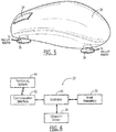
- Figure 6 is a block diagram of one embodiment of a non-destructive inspection apparatus 22.
- the non-destructive inspection apparatus 22 may include a controller 40 configured to receive input from the operator via the input elements 38. Additionally, the controller 40 may be configured to communicate with the ultrasonic sensor 28, such as to actuate the ultrasonic sensor in response to actuation of a respective input element 38 and to receive a representation of the return signals from the ultrasonic sensor.
- the non-destructive inspection apparatus 22 of this embodiment may also include a communications interface 42 including, for example, a transmitter for transmitting information relating to the return signals to the computer 26, such as via a wired or wireless connection.
- a method for the non-destructive inspection of a workpiece 24 may include placing an ultrasonic sensor 28 in operable contact with the workpiece. See operation 50.
- the ultrasonic sensor 28 may initially be placed at a predefined position, such as a starting position, upon a workpiece 24.
- the palm of the operator's hand may be supported by the grip 30 so as to permit the operator to handle the non-destructive inspection apparatus in a more ergonomic fashion.
- the method of this embodiment may also emit ultrasonic signals from the ultrasonic sensor 28 into the workpiece 24 while the ultrasonic sensor is positioned at the respective position, such as the starting position. See operation 54.
- the operator may actuate an input element 38 of the grip 30 in order to cause the controller 40 to trigger the emission of the ultrasonic signals from the ultrasonic sensor 28 into the workpiece 24. See operation 52.
- the ultrasonic sensor may receive the return signals. See operation 56.
- the return signals may be stored, processed and the like onboard the non-destructive inspection apparatus 22, the non-destructive inspection apparatus of one embodiment may be configured to provide information relating to the return signals to a computer 26, such as via wireless communications, to facilitate offboard processing, storage and/or display of information relating to the return signals by the computer. See operation 58.
- the operator may actuate an input element 38 of the grip 30 in order to cause the controller 40 to trigger the communications interface 42 to transmit the information relating to the return signals to the computer 26.
- the information relating to the return signals may relate to various characteristics of the workpiece 24 including the thickness of the workpiece, anomalies within the portion of the workpiece under inspection and the like.
- the ultrasonic sensor 28 may receive the return signals and the non-destructive inspection apparatus 22 may provide information regarding return signals to the computer 26, either following receipt of the return signals at each position or in a batch form following the receipt of the return signals for all or at least a plurality of positions across the workpiece.
- the non-destructive inspection apparatus of an example embodiment provides an ergonomic device for reducing operator exertion and exhaustion, thereby permitting an operator to repetitively utilize the non-destructive inspection apparatus for longer periods of time than in instances in which the operator had to grasp a much smaller ultrasonic sensor 10 as shown in Figure 1 .
- the non-destructive inspection apparatus 22 may be manually moved across a workpiece 24 so as to inspect the workpiece at a plurality of locations. The operator may identify the locations to be inspected. Alternatively, the non-destructive inspection apparatus 22 may communicate with a positioning system 44 as shown in Figure 6 in order to identify the locations to be inspected.
- the positioning system 44 may be embodied in various manners. In one embodiment, however, the positioning system 44 includes a plurality of global positioning system (GPS) satellites or a plurality of pseudolites, such as a plurality of transceivers positioned about the facility in which the inspection is being performed.
- GPS global positioning system
- the positioning system 44 of this embodiment is in communication with the communication interface 42 of the non-destructive inspection apparatus 22 so as to provide positioning signals that may be processed by the controller 40 or by a positioning module, such as a GPS module, that is in communication with the controller. Based upon the positioning signals, the controller 40 or an associated positioning module may determine the location of the non-destructive inspection apparatus 22. As such, the communication interface 42 of this embodiment may not only provide information relating to the return signals to the computer 26, but may also identify the location at which the return signals were captured based upon the positioning signals provided by the positioning system 44.
- the positioning system 44 may include a projector, such as a laser projector, for illuminating the workpiece 24 with one or more markers, such as illuminated dots.
- the positioning system 44 such as the projector, may be initially aligned and calibrated with the workpiece 24 such that the markers with which the workpiece is illuminated indicated locations to be inspected.
- the non-destructive inspection apparatus 22 may be moved into alignment with the marker.
- the communication interface 42 may include a receiver, such as a photodiode and, in one embodiment, a lens, in order to receive the marker, such as a laser signal, provided by the positioning system 44.
- the controller 40 may determine that the non-destructive inspection apparatus 22 is properly located relative to the workpiece 24 and may then interrogate the underlying portion of the workpiece.
- the positioning system 44 of this embodiment including the projector may be configured in various manners and, in one embodiment, is configured to illuminate the workpiece 24 with a pattern that defines a plurality of locations to be inspected and, in another embodiment, sequentially illuminates the workpiece with first one marker defining a first location that is interrogated and then another marker following inspection of the workpiece at the first location such that the inspection of the workpiece proceeds from one marker to the next across the workpiece.
- the positioning system 44 of one embodiment may include a combination of the the foregoing embodiments including the provision of positioning signals from a plurality of GPS satellites or pseudolites and the illumination of the workpiece 24 by a projector.
- the positioning signals from a plurality of GPS satellites or pseudolites may provide for general positioning of the non-destructive inspection apparatus 22 and the illumination of the workpiece 24 by the projector may provide for a finer or more granular level of positioning. While several examples of a positioning system 44 have been provided, the non-destructive inspection apparatus 22 may interact with a variety of different types of positioning systems that identify the location upon the workpiece 24 to be inspected.
Landscapes
- Physics & Mathematics (AREA)
- Health & Medical Sciences (AREA)
- Life Sciences & Earth Sciences (AREA)
- Chemical & Material Sciences (AREA)
- Analytical Chemistry (AREA)
- Biochemistry (AREA)
- General Health & Medical Sciences (AREA)
- General Physics & Mathematics (AREA)
- Immunology (AREA)
- Pathology (AREA)
- Acoustics & Sound (AREA)
- Investigating Or Analyzing Materials By The Use Of Ultrasonic Waves (AREA)
Applications Claiming Priority (1)
| Application Number | Priority Date | Filing Date | Title |
|---|---|---|---|
| US13/298,325 US9057686B2 (en) | 2011-11-17 | 2011-11-17 | Non-destructive inspection apparatus having an ergonomic grip and associated method |
Publications (3)
| Publication Number | Publication Date |
|---|---|
| EP2594934A2 EP2594934A2 (en) | 2013-05-22 |
| EP2594934A3 EP2594934A3 (en) | 2015-03-25 |
| EP2594934B1 true EP2594934B1 (en) | 2020-08-12 |
Family
ID=47257481
Family Applications (1)
| Application Number | Title | Priority Date | Filing Date |
|---|---|---|---|
| EP12192219.9A Active EP2594934B1 (en) | 2011-11-17 | 2012-11-12 | Non-destructive inspection apparatus having an ergonomic grip and associated method |
Country Status (6)
| Country | Link |
|---|---|
| US (1) | US9057686B2 (enExample) |
| EP (1) | EP2594934B1 (enExample) |
| JP (1) | JP6157840B2 (enExample) |
| CN (1) | CN103123337B (enExample) |
| BR (1) | BR102012029193B1 (enExample) |
| CA (1) | CA2792703C (enExample) |
Families Citing this family (4)
| Publication number | Priority date | Publication date | Assignee | Title |
|---|---|---|---|---|
| US9945939B1 (en) * | 2013-05-06 | 2018-04-17 | Lokdon Llc | Method for determining a location of an emitter |
| DE102014103945A1 (de) * | 2014-03-21 | 2015-09-24 | Ge Sensing & Inspection Technologies Gmbh | Vorrichtung zur zerstörungsfreien Ultraschallprüfung von Werkstücken mit einer verbesserten Handhabbarkeit sowie Verfahren hierzu |
| CN105784515A (zh) * | 2015-12-08 | 2016-07-20 | 四川大学 | 真空超声振动疲劳实验系统 |
| CN109435542A (zh) * | 2018-09-17 | 2019-03-08 | 苏州涵轩信息科技有限公司 | 伸缩式圆规尺 |
Family Cites Families (16)
| Publication number | Priority date | Publication date | Assignee | Title |
|---|---|---|---|---|
| JPH05142213A (ja) * | 1991-11-20 | 1993-06-08 | Osaka Gas Co Ltd | 超音波測定装置の探触子ホルダー及び超音波測定装置 |
| JPH09276267A (ja) * | 1996-04-16 | 1997-10-28 | Ge Yokogawa Medical Syst Ltd | 超音波探触子用グリップキャップおよび超音波探触子 |
| US5897503A (en) | 1997-08-01 | 1999-04-27 | Acuson Corporation | Ultrasound transducer probe having case handle grip surfaces |
| JP3107298B2 (ja) * | 1998-02-20 | 2000-11-06 | 日本電気株式会社 | マウス型情報入力装置 |
| DE10300383B4 (de) * | 2003-01-09 | 2005-05-12 | Windhoff Bahn- Und Anlagentechnik Gmbh | Rohrleitungsmolch |
| WO2005038449A1 (en) * | 2003-10-16 | 2005-04-28 | Commonwealth Scientific And Industrial Research Organisation | A probe for non-destructive testing |
| US7222514B2 (en) | 2004-06-21 | 2007-05-29 | The Boeing Company | Laminate material testing methods and systems |
| US20060173331A1 (en) * | 2004-11-24 | 2006-08-03 | Siemens Medical Solutions Usa, Inc. | Ergonomic transducer housing and methods for ultrasound imaging |
| JP2006184028A (ja) * | 2004-12-24 | 2006-07-13 | Chugoku Electric Power Co Inc:The | 聴診点検に用いる自走ロボット |
| CN1956636B (zh) * | 2005-10-26 | 2010-09-29 | 鸿富锦精密工业(深圳)有限公司 | 电子装置及其可更换外壳 |
| US7478569B2 (en) | 2005-12-02 | 2009-01-20 | The Boeing Company | Non-destructive inspection system with flexible display and associated method |
| EP1935343B1 (en) | 2006-12-18 | 2011-10-26 | Esaote S.p.A. | Ergonomic housing for electroacoustic transducers and ultrasound probe with said housing |
| JP5582689B2 (ja) * | 2007-09-21 | 2014-09-03 | 東芝プラントシステム株式会社 | 超音波検査装置、超音波検査装置に用いられる超音波プローブ装置、および超音波検査方法 |
| US8100015B2 (en) * | 2007-11-20 | 2012-01-24 | Kabushiki Kaisha Toshiba | Ultrasonic inspection apparatus and ultrasonic probe used for same |
| JP5422464B2 (ja) * | 2010-03-31 | 2014-02-19 | 中日本ハイウェイ・エンジニアリング名古屋株式会社 | 打撃検査装置 |
| CN202488512U (zh) * | 2012-02-23 | 2012-10-10 | 丁绍杰 | 一种手机移动电源结构改良 |
-
2011
- 2011-11-17 US US13/298,325 patent/US9057686B2/en not_active Expired - Fee Related
-
2012
- 2012-10-16 CA CA2792703A patent/CA2792703C/en not_active Expired - Fee Related
- 2012-11-12 EP EP12192219.9A patent/EP2594934B1/en active Active
- 2012-11-14 BR BR102012029193-2A patent/BR102012029193B1/pt not_active IP Right Cessation
- 2012-11-16 JP JP2012252496A patent/JP6157840B2/ja not_active Expired - Fee Related
- 2012-11-19 CN CN201210468043.3A patent/CN103123337B/zh not_active Expired - Fee Related
Non-Patent Citations (1)
| Title |
|---|
| None * |
Also Published As
| Publication number | Publication date |
|---|---|
| EP2594934A2 (en) | 2013-05-22 |
| BR102012029193B1 (pt) | 2020-11-10 |
| BR102012029193A2 (pt) | 2013-10-08 |
| CA2792703C (en) | 2018-10-09 |
| US9057686B2 (en) | 2015-06-16 |
| EP2594934A3 (en) | 2015-03-25 |
| JP6157840B2 (ja) | 2017-07-05 |
| CN103123337A (zh) | 2013-05-29 |
| US20130125657A1 (en) | 2013-05-23 |
| CN103123337B (zh) | 2017-10-13 |
| CA2792703A1 (en) | 2013-05-17 |
| JP2013108982A (ja) | 2013-06-06 |
Similar Documents
| Publication | Publication Date | Title |
|---|---|---|
| EP2594934B1 (en) | Non-destructive inspection apparatus having an ergonomic grip and associated method | |
| US8185327B2 (en) | Monitoring of composite materials | |
| US10436767B2 (en) | Apparatus and method for non-destructive testing of concrete | |
| US20070095160A1 (en) | Structural assessment and monitoring system and associated method | |
| EP1746418A2 (en) | An inspection device | |
| US20100024559A1 (en) | Hybrid Inspection System And Method Employing Both Air-Coupled And Liquid-Coupled Transducers | |
| EP1873519A3 (en) | Ultrasonic inspection and repair mode selection | |
| JP2017049232A (ja) | 製造物の表面に設置した可撓性の二次元アレイを用いた超音波検査 | |
| JP2013200308A (ja) | 不整合を示すための表面可視化システム | |
| EP2631641A1 (en) | Ultrasonic flaw detection device, ultrasonic transducer, and ultrasonic flaw detection method | |
| JP2006187589A (ja) | 超音波診断システム及び方法 | |
| CN105395217A (zh) | 探头 | |
| KR101564645B1 (ko) | 초음파 탐촉자용 접촉 매질 패드 및 이를 이용한 초음파 검사장치 | |
| US9470662B2 (en) | Sensor module with adaptive backing layer | |
| CA3189242A1 (en) | Ultrasound scanning system with adaptive gating | |
| EP2839887A2 (en) | Acoustic probe and method of manufacturing the same | |
| CN109561882A (zh) | 用于确定脂肪身体组织成分和瘦肉身体组织成分的系统和方法 | |
| JP2015080600A (ja) | 超音波プローブおよび超音波画像装置 | |
| JP2013108982A5 (enExample) | ||
| US10881381B2 (en) | Ultrasonic diagnostic system | |
| GB2606699A (en) | Ultrasonic coupling | |
| KR101935930B1 (ko) | 임펄스 기법을 이용한 피검사체에 대한 동탄성계수 및 푸아송비 측정장비 및 그 방법 | |
| JP2024096577A (ja) | 音波検査装置、音波検査方法、及び音波検査装置用保持具 | |
| AU2011100029A4 (en) | Mechanically Driven Medical Scanning Device | |
| WO2024042960A1 (ja) | 電子装置、医療機器および超音波診断装置 |
Legal Events
| Date | Code | Title | Description |
|---|---|---|---|
| PUAI | Public reference made under article 153(3) epc to a published international application that has entered the european phase |
Free format text: ORIGINAL CODE: 0009012 |
|
| AK | Designated contracting states |
Kind code of ref document: A2 Designated state(s): AL AT BE BG CH CY CZ DE DK EE ES FI FR GB GR HR HU IE IS IT LI LT LU LV MC MK MT NL NO PL PT RO RS SE SI SK SM TR |
|
| AX | Request for extension of the european patent |
Extension state: BA ME |
|
| RIN1 | Information on inventor provided before grant (corrected) |
Inventor name: HUSKAMP, CHRISTOPHER S. Inventor name: FONDA, JAMES WILLIAM |
|
| PUAL | Search report despatched |
Free format text: ORIGINAL CODE: 0009013 |
|
| AK | Designated contracting states |
Kind code of ref document: A3 Designated state(s): AL AT BE BG CH CY CZ DE DK EE ES FI FR GB GR HR HU IE IS IT LI LT LU LV MC MK MT NL NO PL PT RO RS SE SI SK SM TR |
|
| AX | Request for extension of the european patent |
Extension state: BA ME |
|
| RIC1 | Information provided on ipc code assigned before grant |
Ipc: G01N 29/04 20060101ALI20150219BHEP Ipc: A61B 8/00 20060101ALI20150219BHEP Ipc: G01N 29/265 20060101ALI20150219BHEP Ipc: G01N 29/22 20060101AFI20150219BHEP |
|
| 17P | Request for examination filed |
Effective date: 20150909 |
|
| RBV | Designated contracting states (corrected) |
Designated state(s): AL AT BE BG CH CY CZ DE DK EE ES FI FR GB GR HR HU IE IS IT LI LT LU LV MC MK MT NL NO PL PT RO RS SE SI SK SM TR |
|
| STAA | Information on the status of an ep patent application or granted ep patent |
Free format text: STATUS: EXAMINATION IS IN PROGRESS |
|
| 17Q | First examination report despatched |
Effective date: 20170817 |
|
| GRAP | Despatch of communication of intention to grant a patent |
Free format text: ORIGINAL CODE: EPIDOSNIGR1 |
|
| STAA | Information on the status of an ep patent application or granted ep patent |
Free format text: STATUS: GRANT OF PATENT IS INTENDED |
|
| INTG | Intention to grant announced |
Effective date: 20200226 |
|
| GRAS | Grant fee paid |
Free format text: ORIGINAL CODE: EPIDOSNIGR3 |
|
| GRAA | (expected) grant |
Free format text: ORIGINAL CODE: 0009210 |
|
| STAA | Information on the status of an ep patent application or granted ep patent |
Free format text: STATUS: THE PATENT HAS BEEN GRANTED |
|
| AK | Designated contracting states |
Kind code of ref document: B1 Designated state(s): AL AT BE BG CH CY CZ DE DK EE ES FI FR GB GR HR HU IE IS IT LI LT LU LV MC MK MT NL NO PL PT RO RS SE SI SK SM TR |
|
| REG | Reference to a national code |
Ref country code: GB Ref legal event code: FG4D |
|
| REG | Reference to a national code |
Ref country code: CH Ref legal event code: EP |
|
| REG | Reference to a national code |
Ref country code: DE Ref legal event code: R096 Ref document number: 602012071733 Country of ref document: DE |
|
| REG | Reference to a national code |
Ref country code: IE Ref legal event code: FG4D |
|
| REG | Reference to a national code |
Ref country code: AT Ref legal event code: REF Ref document number: 1302041 Country of ref document: AT Kind code of ref document: T Effective date: 20200915 |
|
| REG | Reference to a national code |
Ref country code: LT Ref legal event code: MG4D |
|
| REG | Reference to a national code |
Ref country code: NL Ref legal event code: MP Effective date: 20200812 |
|
| PG25 | Lapsed in a contracting state [announced via postgrant information from national office to epo] |
Ref country code: HR Free format text: LAPSE BECAUSE OF FAILURE TO SUBMIT A TRANSLATION OF THE DESCRIPTION OR TO PAY THE FEE WITHIN THE PRESCRIBED TIME-LIMIT Effective date: 20200812 Ref country code: SE Free format text: LAPSE BECAUSE OF FAILURE TO SUBMIT A TRANSLATION OF THE DESCRIPTION OR TO PAY THE FEE WITHIN THE PRESCRIBED TIME-LIMIT Effective date: 20200812 Ref country code: NO Free format text: LAPSE BECAUSE OF FAILURE TO SUBMIT A TRANSLATION OF THE DESCRIPTION OR TO PAY THE FEE WITHIN THE PRESCRIBED TIME-LIMIT Effective date: 20201112 Ref country code: GR Free format text: LAPSE BECAUSE OF FAILURE TO SUBMIT A TRANSLATION OF THE DESCRIPTION OR TO PAY THE FEE WITHIN THE PRESCRIBED TIME-LIMIT Effective date: 20201113 Ref country code: FI Free format text: LAPSE BECAUSE OF FAILURE TO SUBMIT A TRANSLATION OF THE DESCRIPTION OR TO PAY THE FEE WITHIN THE PRESCRIBED TIME-LIMIT Effective date: 20200812 Ref country code: BG Free format text: LAPSE BECAUSE OF FAILURE TO SUBMIT A TRANSLATION OF THE DESCRIPTION OR TO PAY THE FEE WITHIN THE PRESCRIBED TIME-LIMIT Effective date: 20201112 Ref country code: LT Free format text: LAPSE BECAUSE OF FAILURE TO SUBMIT A TRANSLATION OF THE DESCRIPTION OR TO PAY THE FEE WITHIN THE PRESCRIBED TIME-LIMIT Effective date: 20200812 Ref country code: ES Free format text: LAPSE BECAUSE OF FAILURE TO SUBMIT A TRANSLATION OF THE DESCRIPTION OR TO PAY THE FEE WITHIN THE PRESCRIBED TIME-LIMIT Effective date: 20200812 |
|
| REG | Reference to a national code |
Ref country code: AT Ref legal event code: MK05 Ref document number: 1302041 Country of ref document: AT Kind code of ref document: T Effective date: 20200812 |
|
| PG25 | Lapsed in a contracting state [announced via postgrant information from national office to epo] |
Ref country code: RS Free format text: LAPSE BECAUSE OF FAILURE TO SUBMIT A TRANSLATION OF THE DESCRIPTION OR TO PAY THE FEE WITHIN THE PRESCRIBED TIME-LIMIT Effective date: 20200812 Ref country code: NL Free format text: LAPSE BECAUSE OF FAILURE TO SUBMIT A TRANSLATION OF THE DESCRIPTION OR TO PAY THE FEE WITHIN THE PRESCRIBED TIME-LIMIT Effective date: 20200812 Ref country code: LV Free format text: LAPSE BECAUSE OF FAILURE TO SUBMIT A TRANSLATION OF THE DESCRIPTION OR TO PAY THE FEE WITHIN THE PRESCRIBED TIME-LIMIT Effective date: 20200812 Ref country code: PL Free format text: LAPSE BECAUSE OF FAILURE TO SUBMIT A TRANSLATION OF THE DESCRIPTION OR TO PAY THE FEE WITHIN THE PRESCRIBED TIME-LIMIT Effective date: 20200812 Ref country code: IS Free format text: LAPSE BECAUSE OF FAILURE TO SUBMIT A TRANSLATION OF THE DESCRIPTION OR TO PAY THE FEE WITHIN THE PRESCRIBED TIME-LIMIT Effective date: 20201212 |
|
| PG25 | Lapsed in a contracting state [announced via postgrant information from national office to epo] |
Ref country code: DK Free format text: LAPSE BECAUSE OF FAILURE TO SUBMIT A TRANSLATION OF THE DESCRIPTION OR TO PAY THE FEE WITHIN THE PRESCRIBED TIME-LIMIT Effective date: 20200812 Ref country code: CZ Free format text: LAPSE BECAUSE OF FAILURE TO SUBMIT A TRANSLATION OF THE DESCRIPTION OR TO PAY THE FEE WITHIN THE PRESCRIBED TIME-LIMIT Effective date: 20200812 Ref country code: EE Free format text: LAPSE BECAUSE OF FAILURE TO SUBMIT A TRANSLATION OF THE DESCRIPTION OR TO PAY THE FEE WITHIN THE PRESCRIBED TIME-LIMIT Effective date: 20200812 Ref country code: SM Free format text: LAPSE BECAUSE OF FAILURE TO SUBMIT A TRANSLATION OF THE DESCRIPTION OR TO PAY THE FEE WITHIN THE PRESCRIBED TIME-LIMIT Effective date: 20200812 Ref country code: RO Free format text: LAPSE BECAUSE OF FAILURE TO SUBMIT A TRANSLATION OF THE DESCRIPTION OR TO PAY THE FEE WITHIN THE PRESCRIBED TIME-LIMIT Effective date: 20200812 |
|
| REG | Reference to a national code |
Ref country code: DE Ref legal event code: R097 Ref document number: 602012071733 Country of ref document: DE |
|
| PG25 | Lapsed in a contracting state [announced via postgrant information from national office to epo] |
Ref country code: AT Free format text: LAPSE BECAUSE OF FAILURE TO SUBMIT A TRANSLATION OF THE DESCRIPTION OR TO PAY THE FEE WITHIN THE PRESCRIBED TIME-LIMIT Effective date: 20200812 Ref country code: AL Free format text: LAPSE BECAUSE OF FAILURE TO SUBMIT A TRANSLATION OF THE DESCRIPTION OR TO PAY THE FEE WITHIN THE PRESCRIBED TIME-LIMIT Effective date: 20200812 |
|
| PLBE | No opposition filed within time limit |
Free format text: ORIGINAL CODE: 0009261 |
|
| STAA | Information on the status of an ep patent application or granted ep patent |
Free format text: STATUS: NO OPPOSITION FILED WITHIN TIME LIMIT |
|
| PG25 | Lapsed in a contracting state [announced via postgrant information from national office to epo] |
Ref country code: MC Free format text: LAPSE BECAUSE OF FAILURE TO SUBMIT A TRANSLATION OF THE DESCRIPTION OR TO PAY THE FEE WITHIN THE PRESCRIBED TIME-LIMIT Effective date: 20200812 Ref country code: SK Free format text: LAPSE BECAUSE OF FAILURE TO SUBMIT A TRANSLATION OF THE DESCRIPTION OR TO PAY THE FEE WITHIN THE PRESCRIBED TIME-LIMIT Effective date: 20200812 |
|
| REG | Reference to a national code |
Ref country code: CH Ref legal event code: PL |
|
| 26N | No opposition filed |
Effective date: 20210514 |
|
| PG25 | Lapsed in a contracting state [announced via postgrant information from national office to epo] |
Ref country code: IT Free format text: LAPSE BECAUSE OF FAILURE TO SUBMIT A TRANSLATION OF THE DESCRIPTION OR TO PAY THE FEE WITHIN THE PRESCRIBED TIME-LIMIT Effective date: 20200812 Ref country code: LU Free format text: LAPSE BECAUSE OF NON-PAYMENT OF DUE FEES Effective date: 20201112 |
|
| REG | Reference to a national code |
Ref country code: BE Ref legal event code: MM Effective date: 20201130 |
|
| PG25 | Lapsed in a contracting state [announced via postgrant information from national office to epo] |
Ref country code: LI Free format text: LAPSE BECAUSE OF NON-PAYMENT OF DUE FEES Effective date: 20201130 Ref country code: SI Free format text: LAPSE BECAUSE OF FAILURE TO SUBMIT A TRANSLATION OF THE DESCRIPTION OR TO PAY THE FEE WITHIN THE PRESCRIBED TIME-LIMIT Effective date: 20200812 Ref country code: CH Free format text: LAPSE BECAUSE OF NON-PAYMENT OF DUE FEES Effective date: 20201130 |
|
| PG25 | Lapsed in a contracting state [announced via postgrant information from national office to epo] |
Ref country code: IE Free format text: LAPSE BECAUSE OF NON-PAYMENT OF DUE FEES Effective date: 20201112 |
|
| PGFP | Annual fee paid to national office [announced via postgrant information from national office to epo] |
Ref country code: FR Payment date: 20211124 Year of fee payment: 10 Ref country code: DE Payment date: 20211126 Year of fee payment: 10 Ref country code: GB Payment date: 20211129 Year of fee payment: 10 |
|
| PG25 | Lapsed in a contracting state [announced via postgrant information from national office to epo] |
Ref country code: TR Free format text: LAPSE BECAUSE OF FAILURE TO SUBMIT A TRANSLATION OF THE DESCRIPTION OR TO PAY THE FEE WITHIN THE PRESCRIBED TIME-LIMIT Effective date: 20200812 Ref country code: MT Free format text: LAPSE BECAUSE OF FAILURE TO SUBMIT A TRANSLATION OF THE DESCRIPTION OR TO PAY THE FEE WITHIN THE PRESCRIBED TIME-LIMIT Effective date: 20200812 Ref country code: CY Free format text: LAPSE BECAUSE OF FAILURE TO SUBMIT A TRANSLATION OF THE DESCRIPTION OR TO PAY THE FEE WITHIN THE PRESCRIBED TIME-LIMIT Effective date: 20200812 |
|
| PG25 | Lapsed in a contracting state [announced via postgrant information from national office to epo] |
Ref country code: MK Free format text: LAPSE BECAUSE OF FAILURE TO SUBMIT A TRANSLATION OF THE DESCRIPTION OR TO PAY THE FEE WITHIN THE PRESCRIBED TIME-LIMIT Effective date: 20200812 |
|
| PG25 | Lapsed in a contracting state [announced via postgrant information from national office to epo] |
Ref country code: PT Free format text: LAPSE BECAUSE OF FAILURE TO SUBMIT A TRANSLATION OF THE DESCRIPTION OR TO PAY THE FEE WITHIN THE PRESCRIBED TIME-LIMIT Effective date: 20200812 Ref country code: BE Free format text: LAPSE BECAUSE OF NON-PAYMENT OF DUE FEES Effective date: 20201130 |
|
| REG | Reference to a national code |
Ref country code: DE Ref legal event code: R119 Ref document number: 602012071733 Country of ref document: DE |
|
| GBPC | Gb: european patent ceased through non-payment of renewal fee |
Effective date: 20221112 |
|
| PG25 | Lapsed in a contracting state [announced via postgrant information from national office to epo] |
Ref country code: GB Free format text: LAPSE BECAUSE OF NON-PAYMENT OF DUE FEES Effective date: 20221112 Ref country code: DE Free format text: LAPSE BECAUSE OF NON-PAYMENT OF DUE FEES Effective date: 20230601 |
|
| PG25 | Lapsed in a contracting state [announced via postgrant information from national office to epo] |
Ref country code: FR Free format text: LAPSE BECAUSE OF NON-PAYMENT OF DUE FEES Effective date: 20221130 |