EP2594918B1 - Härtetester und Härtetestverfahren - Google Patents
Härtetester und Härtetestverfahren Download PDFInfo
- Publication number
- EP2594918B1 EP2594918B1 EP12176081.3A EP12176081A EP2594918B1 EP 2594918 B1 EP2594918 B1 EP 2594918B1 EP 12176081 A EP12176081 A EP 12176081A EP 2594918 B1 EP2594918 B1 EP 2594918B1
- Authority
- EP
- European Patent Office
- Prior art keywords
- image data
- indentation
- sample
- hardness
- curvature
- Prior art date
- Legal status (The legal status is an assumption and is not a legal conclusion. Google has not performed a legal analysis and makes no representation as to the accuracy of the status listed.)
- Active
Links
Images



Classifications
-
- G—PHYSICS
- G01—MEASURING; TESTING
- G01N—INVESTIGATING OR ANALYSING MATERIALS BY DETERMINING THEIR CHEMICAL OR PHYSICAL PROPERTIES
- G01N3/00—Investigating strength properties of solid materials by application of mechanical stress
- G01N3/40—Investigating hardness or rebound hardness
- G01N3/42—Investigating hardness or rebound hardness by performing impressions under a steady load by indentors, e.g. sphere, pyramid
-
- G—PHYSICS
- G01—MEASURING; TESTING
- G01N—INVESTIGATING OR ANALYSING MATERIALS BY DETERMINING THEIR CHEMICAL OR PHYSICAL PROPERTIES
- G01N2203/00—Investigating strength properties of solid materials by application of mechanical stress
- G01N2203/0058—Kind of property studied
- G01N2203/0076—Hardness, compressibility or resistance to crushing
- G01N2203/0078—Hardness, compressibility or resistance to crushing using indentation
-
- G—PHYSICS
- G01—MEASURING; TESTING
- G01N—INVESTIGATING OR ANALYSING MATERIALS BY DETERMINING THEIR CHEMICAL OR PHYSICAL PROPERTIES
- G01N2203/00—Investigating strength properties of solid materials by application of mechanical stress
- G01N2203/02—Details not specific for a particular testing method
- G01N2203/06—Indicating or recording means; Sensing means
- G01N2203/0641—Indicating or recording means; Sensing means using optical, X-ray, ultraviolet, infrared or similar detectors
- G01N2203/0647—Image analysis
-
- G—PHYSICS
- G01—MEASURING; TESTING
- G01N—INVESTIGATING OR ANALYSING MATERIALS BY DETERMINING THEIR CHEMICAL OR PHYSICAL PROPERTIES
- G01N2203/00—Investigating strength properties of solid materials by application of mechanical stress
- G01N2203/02—Details not specific for a particular testing method
- G01N2203/06—Indicating or recording means; Sensing means
- G01N2203/067—Parameter measured for estimating the property
- G01N2203/0682—Spatial dimension, e.g. length, area, angle
Definitions
- the present invention relates to a hardness tester and a hardness test method.
- a press-type hardness test method which measures hardness of a sample by pressing an indenter in the shape of a polygonal pyramid onto the surface of the sample, and measuring the lengths of the diagonal lines of a polygonal indentation formed on the surface of the sample.
- a hardness test method the Vickers hardness test method, the Knoop hardness test method, and the like are well known. The method is often used to evaluate mechanical properties of metallic materials.
- the Vickers hardness test method uses an indenter in the shape of a square (or rhombic) pyramid made of diamond, and shows the hardness of a sample from the perspective of a relationship between the average value of the lengths of the two diagonal lines of an indentation in the shape of a square pyramid formed on the surface of the sample and a force (a load) pressed onto the sample by the indenter.
- the Knoop hardness test method uses an indenter in the shape of a rhombic pyramid (an extended pyramid) made of diamond, and shows the hardness of a sample from the perspective of a relationship between the length of a longer diagonal line of the two diagonal lines of an indentation in the shape of a rhombic pyramid formed on the surface of the sample and a force (a load) pressed onto the sample by the indenter.
- a hardness test and tissue observation of a metallic material are often carried out together.
- a hardness tester when a hardness test of a metallic material is carried out, binarization processing is performed on a picked-up image of the surface of a sample picked up by an image pickup section on the basis of determination whether or not a brightness value is less than a predetermined value, so as to extract an indentation region formed on the surface of the sample, which is disclosed by Japanese Patent No. 4029832 , for example.
- Japanese Patent No. 3557765 images of the surface of a sample are picked up before and after an indentation is formed thereon, and an indentation region is extracted based on a difference between the picked-up image which is picked up before the indentation is formed and the picked-up image which is picked up after the indentation is formed.
- Japanese Patent No. 3367297 discloses an indentation type hardness tester in which multiple virtual shape patterns are stored in a virtual pattern memory in advance.
- the virtual shape patterns are put at the vertex position of an optical image of a recess formed on the surface of a sample when an indentation is made. It is checked whether they match with it or not.
- the matched virtual shape pattern forms the vertex position of the optical image of the recess, and the position of the vertex of the recess is determined for calculating the diagonal line size of the recess.
- Japanese Patent No. 3557765 requires two picked-up images of the surface of a sample, and hence processing is complicated.
- the image pickup position differs even a little between before and after an indentation is formed on the surface of a sample, which is caused by the position of an image pickup section being shifted or the like, a proper difference cannot be obtained. As a result, an indentation region cannot be extracted correctly.
- the invention provides a hardness tester in accordance with claim 1.
- the invention provides a hardness test method in accordance with claim 6. Further aspects of the invention are set forth in the dependent claims, the drawings and the following description of embodiments.
- Objects of the present invention are to provide a hardness tester and a hardness test method which can correctly and easily extract an indentation region even from a sample on which etching processing is performed.
- a hardness tester which applies a predetermined test force with an indenter to a surface of a sample placed on a sample support to form an indentation, and measures a dimension of the indentation to measure hardness of the sample
- the hardness tester including: an image pickup control section which controls an image pickup section to pick up an image of the surface of the sample, to obtain picked-up image data of the surface of the sample; an indentation region extraction section which (i) binarizes the picked-up image data, (ii) erodes and dilates the binarized image data, and (iii) performs distance transform on the eroded-and-dilated image data, to extract a closed region corresponding to a shape of the indenter using the distance-transformed image data; an indentation apex extraction section which extracts an indentation-measurement-use apex on the basis of the extracted closed region,
- a hardness tester which applies a predetermined test force with an indenter to a surface of a sample placed on a sample support to form an indentation, and measures a dimension of the indentation to measure hardness of the sample
- the hardness tester including: an image pickup control section which controls an image pickup section to pick up an image of the surface of the sample, to obtain picked-up image data of the surface of the sample; an indentation region extraction section which obtains curvature image data on the basis of a brightness value of the picked-up image data, and extracts a flat part where a curvature is less than a predetermined value as an indentation region referring to the obtained curvature image data; and/or a hardness calculation section which calculates the hardness of the sample on the basis of the indentation region.
- a hardness test method which applies a predetermined test force with an indenter to a surface of a sample placed on a sample support to form an indentation, and measures a dimension of the indentation to measure hardness of the sample
- the hardness test method including: an image pickup control step of controlling an image pickup step to pick up an image of the surface of the sample, to obtain picked-up image data of the surface of the sample; an indentation region extraction step of (i) binarizing the picked-up image data, (ii) eroding and dilating the binarized image data, and (iii) performing distance transform on the eroded-and-dilated image data, to extract a closed region corresponding to a shape of the indenter using the distance-transformed image data; an indentation apex extraction step of extracting an indentation-measurement-use apex on the basis of the extracted closed
- a hardness test method which applies a predetermined test force with an indenter to a surface of a sample placed on a sample support to form an indentation, and measures a dimension of the indentation to measure hardness of the sample
- the hardness test method including: an image pickup control step of controlling an image pickup step to pick up an image of the surface of the sample, to obtain picked-up image data of the surface of the sample; an indentation region extraction step of obtaining curvature image data on the basis of a brightness value of the picked-up image data, and extracting a flat part where a curvature is less than a predetermined value as an indentation region referring to the obtained curvature image data; and/or a hardness calculation step of calculating the hardness of the sample on the basis of the indentation region.
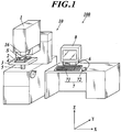
- an X direction, a Y direction and a Z direction shown in FIG. 1 respectively represent a right-left direction, a front-back direction and an up-down direction.
- an X-Y plane represents a horizontal plane.
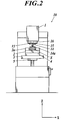
- a hardness tester 100 is a Vickers hardness tester which includes an indenter 14a in the shape of a rhombic pyramid. As shown in FIGS. 1 and 2 , the hardness tester 100 includes a tester main body 10, a control section 6, an operation section 7, and a monitor 8.
- the tester main body 10 includes a hardness measurement section 1 which measures the hardness of a sample S, a sample support 2 on which the sample S is placed, an XY stage 3 which moves the sample support 2, an AF stage 4 with which the surface of the sample S is in focus, and an up-down mechanism section 5 which moves the sample support 2 (the XY stage 3 and the AF stage 4) up and down.
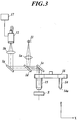
- the hardness measurement section 1 includes an illuminator 11 which illuminates the surface of the sample S, a CCD camera 12 which picks up an image of the surface of the sample S, and a turret 16.
- the turret 16 is provided with object lenses 15 and an indenter shaft 14 provided with the indenter 14a, and rotates in such a way that the indenter shaft 14 (i.e. the indenter 14a) or any one of the object lenses 15 is positioned above the sample S.
- the illuminator 11 illuminates the surface of the sample S by emitting light.
- the light emitted from the illuminator 11 reaches the surface of the sample S via a lens 1a, a half mirror 1d, a mirror 1e, and one of the object lenses 15.
- the CCD camera 12 picks up an image of the surface of the sample S and an indentation formed on the surface of the sample S so as to obtain image data thereof on the basis of reflected light entered from the surface of the sample S via one of the object lenses 15, the mirror 1e, the half mirror 1d, a mirror 1g, and a lens 1h, and outputs the obtained image data to the control section 6 via a frame grabber 17.
- the frame grabber 17 can store and accumulate image data of a plurality of frames at a time.
- the CCD camera 12 functions as an image pickup section.
- the indenter shaft 14 is moved to the sample S placed on the sample support 2 by a load mechanism section (not shown) which is driven in accordance with a control signal outputted by the control section 6, and presses the indenter 14a disposed at one end (the tip end) of the indenter shaft 14 onto the surface of the sample S with a predetermined test force.
- the object lenses 15 are condensing lenses having different magnifications.
- the object lenses 15 are held on the underside (undersurface) of the turret 16. Any of the object lenses 15 is positioned above the sample S by rotation of the turret 16 so as to uniformly illuminate the surface of the sample S with the light emitted from the illuminator 11.
- the indenter shaft 14 and the object lenses 15 are mounted on the underside of the turret 16.
- the turret 16 rotates having the Z direction as a rotation center, thereby positioning the indenter shaft 14 or one of the object lenses 15 above the sample S. That is, positioning the indenter shaft 14 above the sample S makes it possible to form an indentation on the surface of the sample S, and positioning one of the object lenses 15 above the sample S makes it possible to observe the formed indentation.
- the sample support 2 fixes the sample S, which is placed on the upper-side thereof, thereon with a sample fixing section 2a.
- the XY stage 3 is driven by a drive mechanism section (not shown) which is driven in accordance with a control signal outputted by the control section 6, and moves the sample support 2 in a direction (the X direction or the Y direction) perpendicular to a moving direction (the Z direction) of the indenter 14a.
- the AF stage 4 is driven in accordance with a control signal outputted by the control section 6, and moves the sample support 2 up and down finely on the basis of the image data of the image picked up by the CCD camera 12 so that the surface of the sample S is in focus.
- the up-down mechanism section 5 is driven in accordance with a control signal outputted by the control section 6, and moves the sample support 2 (the XY stage 3 and the AF stage 4) in the up-down direction, so as to change a relative distance between the sample support 2 and the object lenses 15.
- the operation section 7 includes a keyboard 71 and a mouse 72, and allows a user to make an input operation to carry out a hardness test.
- a predetermined input operation is made with the operation section 7, a predetermined operation signal corresponding to the input operation is outputted to the control section 6.
- the operation section 7 allows a user to choose a condition to determine a focal position for an indentation with the keyboard 71, the mouse 72 or the like.
- the operation section 7 allows a user to specify a range within which the sample support 2 (the up-down mechanism section 5 and the AF stage 4) can move, namely, to specify a range of relative distances between the sample support 2 and the object lenses 15.
- the operation section 7 allows a user to input test condition values used for a hardness test carried out by the hardness tester 100.
- the inputted test condition values are sent to the control section 6.
- the test condition values are, for example, values of material properties of the sample S, a test force (N) applied to the sample S by the indenter 14a, the magnifications of the object lenses 15, and the like.
- the operation section 7 allows a user to choose either a manual mode in which the focal position for an indentation is decided manually or an automatic mode in which the focal position for an indentation is decided automatically.
- the monitor 8 is constituted of a display device such as an LCD (Liquid Crystal Display), and displays setting conditions for a hardness test inputted with the operation section 7, a result of the hardness test, the image of the surface of the sample S and the indentation formed on the surface of the sample S picked up by the CCD camera 12, and the like.
- a display device such as an LCD (Liquid Crystal Display)
- LCD Liquid Crystal Display
- the monitor 8 functions as a display section.
- the control section 6 includes a CPU (Central Processing Unit) 61, a RAM (Random Access Memory) 62, and a storage section 63.
- the control section 6 has a function to perform operation control to carry out a predetermined hardness test or the like by executing predetermined programs stored in the storage section 63.
- the CPU 61 reads a processing program or the like stored in the storage section 63, and loads the read processing program into the RAM 62, so as to perform processing, thereby controlling the hardness tester 100 overall.
- the RAM 62 decompresses the processing program or the like executed by the CPU 61 in a program storage region of the RAM 62. Furthermore, the RAM 62 stores input data, a processing result obtained by the processing program or the like being executed, and the like in a data storage region of the RAM 62.
- the storage section 63 includes a recording medium (not shown) which stores programs, data, and the like.
- the recording medium is constituted of a semiconductor memory or the like.
- the storage section 63 stores various data and various processing programs to realize a function with which the CPU 61 controls the hardness tester 100 overall, data processed by the programs being executed, and the like. More specifically, the storage section 63 stores an XY stage control program, an autofocus program, an indentation forming program, an image pickup control program, an indentation region extraction program, an indentation apex extraction program, a hardness calculation program, a display control program, and the like.
- the CPU 61 executes the XY stage control program stored in the storage section 63, so as to move the XY stage 3 in such a way that a predetermined region of the surface of the sample S is positioned just under the CCD camera 12.
- the CPU 61 executes the autofocus program stored in the storage section 63, so as to move the AF stage 4 up and down on the basis of the image data (picked-up image data) obtained by the CCD camera 12 of the hardness measurement section 1 so that the surface of the sample S is automatically in focus.
- the CPU 61 executes the indentation forming program stored in the storage section 63, so as to form an indentation by pressing the indenter 14a onto the surface of the sample S with a predetermined test force.
- FIGS. 5 , 7 and 8 Processing shown in FIGS. 5 , 7 and 8 is performed by the CPU 61 executing the programs stored in the storage section 63. In the embodiment, etching processing is performed on the surface of the sample S.
- the CPU 61 executes the image pickup control program stored in the storage section 63, so as to control the CCD camera 12 to pick up an image of the surface of the sample S, thereby obtaining image data (picked-up image data) of the surface of the sample S (Step S1: an image pickup control step) .
- Step S1 an image pickup control step
- Step S2 an indentation region extraction step
- the CPU 61 refers to the image data of the surface of the sample S obtained at Step S1 in FIG. 5 , and determines whether or not shading correction is necessary to be performed thereon (Step S21) .
- the shading correction is processing to correct uneven brightness of an image caused by the properties of an optical system and/or an image pickup system, so as to obtain the image having even brightness .
- the determination at Step S21 is made by determining whether or not, on the basis of difference of brightness values of small regions at four corners of the image data, dispersion of the brightness values of the small regions is equal to or more than a predetermined value.
- Step S21 When determining that the shading correction is necessary (Step S21; YES), the CPU 61 performs the shading correction on the image data of the surface of the sample S (Step S22), and then moves to Step S23. On the other hand, when determining that the shading correction is unnecessary (Step S21; NO), the CPU 61 moves to Step S23 without performing the shading correction.
- the CPU 61 performs binarization processing using a gray value on the image data of the surface of the sample S, the image data being obtained at Step S1 in FIG. 5 or undergoing the shading correction at Step S22 (Step S23) . More specifically, the CPU 61 converts the image data of an original image (the image of the surface of the sample S) which is a black-and-white grayscale image into image data having two gradations, namely, black and white.
- the CPU 61 replaces the gradation of the pixel with black, and when the brightness value of a pixel is less than the predetermined threshold value, the CPU 61 replaces the gradation of the pixel with white. Consequently, the obtained image data of the surface of the sample S is displayed in such a way that the part replaced with black by the binarization processing is blacker than its corresponding part of the original image, and the part replaced with white by the binarization processing is whiter than its corresponding part of the original image.
- the brightness values of the pixels of the indentation region of the indentation formed on the surface of the sample S are lower than those of the pixels of the background, and hence the indentation region is displayed by white pixels.
- the image data binarized (binarized image data) at Step S23 is stored in the storage section 63.
- the CPU 61 generates copy data of the image data binarized at Step S23, and erodes and dilates the binarized image data using the copy data of the binarized image data. Furthermore, the CPU 61 performs distance transform on the eroded-and-dilated image data. As for the erosion, the dilation and the distance transform, well-known technologies or technologies proposed by the present inventor in Japanese Patent Application No. 2011-201305 can be used. Hence, detailed description thereof is omitted.
- the CPU 61 extracts a closed region (closed region extraction processing) corresponding to the shape of the indenter 14a, using the binarized image data undergoing the distance transform (distance-transformed image data) at Step S23 or binarized image data undergoing distance transform (distance-transformed image data) at Step S264 in FIG. 8 described below (Step S24).
- a well-known technology or a technology proposed by the present inventor in Japanese Patent Application No. 2011-201305 can be used. Hence, detailed description thereof is omitted.
- the CPU 61 determines whether or not the closed region is extracted by the closed region extraction processing performed at Step S24 (Step S25). That is, the CPU 61 determines whether or not the closed region as an indentation region candidate is extracted, on the basis of the binarized image data.
- the indentation region candidate is a region which is a candidate for the indentation region formed on the surface of the sample S. More specifically, the determination at Step S25 is made by determining whether or not one or more closed regions are stored in the storage section 63. When determining that one or more closed regions are stored in the storage section 63, namely, determining that the closed region is extracted (Step S25; YES), the CPU 61 ends the indentation region extraction processing, and moves to Step S3 in FIG.
- Step S26 when determining that one or more closed regions are not stored in the storage section 63, namely, determining that the closed region is not extracted (Step S25; NO), the CPU 61 performs binarization processing using a curvature image (Step S26).
- the CPU 61 performs Gaussian filtering on the brightness values of the image data of the surface of the sample S obtained at Step S1 in FIG. 5 , and then calculates derivatives of the Gaussian-filtered image data (Step S261).
- the Gaussian filtering is processing to smooth the brightness values of an image in order to reduce noise of the image by calculating a rate using the function of Gaussian distribution in such a way that the closer a pixel is to a remarkable pixel, the more a weight therefor is, namely, in such a way that the further a pixel is from a remarkable pixel, the less a weight therefor is.
- the weight is used to calculate the average value of the brightness values.
- A ⁇ 2 G ⁇ I ⁇ x ⁇ x , ⁇ 2 G ⁇ I ⁇ x ⁇ y , ⁇ 2 G ⁇ I ⁇ y ⁇ y
- the CPU 61 calculates a Hessian matrix H for each pixel of the image data (on a pixel basis) using the derivative A calculated at Step S261, and obtains a curvature image data having the absolute value of the Hessian matrix H as the pixel value (Step S262).
- Step S262 the curvature image data shown in FIG. 9 can be obtained, for example.
- the CPU 61 binarizes the curvature image data obtained at Step S262 (Step S263) . More specifically, the CPU 61 converts the curvature image data, which is a black-and-white grayscale image, into image data having two gradations, namely, black and white. That is, if the pixel value (the magnitude of the absolute value of a curvature) of a pixel of the curvature image data is more than a predetermined threshold value, the CPU 61 replaces the pixel with black, and if the pixel value of a pixel thereof is less than the predetermined threshold value, the CPU 61 replaces the gradation of the pixel with white.
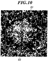
- the indentation region formed on the surface of the sample S has a curvature which is less than that of the background. Hence, as shown in FIG. 10 , the indentation region is displayed by white pixels.
- the CPU 61 performs correction on the image data binarized at Step S263 (Step S264) .
- the correction is processing to correct the binarized image data in such a way that pixels of the binarized image data having a small curvature, the pixels corresponding to the indentation region, form a closed region.
- the correction is performed because, when the curvature image data is binarized at Step S263, as shown in FIG. 10 , the pixels having a small curvature, the pixels corresponding to the indentation region, are sometimes dispersed.
- the CPU 61 extracts a highlight region E1 (corresponding to the apex of the indenter 14a) formed near the center of the image by utilizing the fact that points in the indentation region, the points corresponding to the apex and the ridgelines of the indenter 14a, have high brightness by illumination, and obtains an enclosing rectangle E2 which includes the highlight region E1 and white pixels adjacent to the highlight region E1. Then, the CPU 61 divides the enclosing rectangle E2 into quadrants, and counts the number of white pixels of each quadrant.
- the CPU 61 excludes two quadrants, one having the largest number of white pixels among the quadrants, and one having the smallest number of white pixels among the quadrants, and calculates an average of the number of white pixels of the remaining two quadrants. Then, the CPU 61 corrects the image data in such a way as to form a closed region, on the basis of the average of the number of white pixels and the area of the indentation region estimated from the shape of the indenter 14a. As a result of Step S264, the corrected image shown in FIG. 11 can be obtained, for example.
- the binarized image data corrected at Step S264 is stored in the storage section 63.
- the CPU 61 similarly to Step S23 in FIG. 7 , the CPU 61 generates copy data of the binarized image data, erodes and dilates the binarized image data using the copy data of the binarized image data, and then performs the distance transform on the eroded-and-dilated image data. After performing the distance transform on the eroded-and-dilated image data, the CPU 61 ends the binarization processing using a curvature image, and moves to Step S24 in FIG. 7 .
- the CPU 61 executes the indenter apex extraction program stored in the storage section 63, so as to extract an indentation-measurement-use apex (indentation apex extraction processing) for measuring the size (dimensions) of the indentation on the basis of the contours of the closed region extracted by the indentation region extraction processing performed at Step S2 (Step S3: an indentation apex extraction step).
- an indentation apex extraction processing a well-known technology or a technology proposed by the present inventor in Japanese Patent Application No. 2011-201305 can be used. Hence, detailed description thereof is omitted.
- Step S4 a hardness calculation step. More specifically, the CPU 61 measures the lengths of diagonal lines of the indentation, referring to the coordinates of the indentation-measurement-apex extracted at Step S3, and calculates a hardness value of the sample S on the basis of the measured lengths of the diagonal lines.
- Step S5 a display control step
- the hardness tester 100 in the embodiment includes: an image pickup control section (CPU 61) which controls the CCD camera 12 to pick up an image of the surface of the sample S, to obtain picked-up image data of the surface of the sample S; an indentation region extraction section (CPU 61) which (i) binarizes the picked-up image data, (ii) erodes and dilates the binarized image data, and (iii) performs distance transform on the eroded-and-dilated image data, to extract a closed region corresponding to a shape of the indenter 14a using the distance-transformed image data; an indentation apex extraction section (CPU 61) which extracts an indentation-measurement-use apex on the basis of the extracted closed region, the apex being used to measure the dimension of the indentation; and a hardness calculation section (CPU 61) which calculates the hardness of the sample S on the basis of the extracted apex, wherein the inden
- the closed region corresponding to the shape of the indenter 14a can be extracted by obtaining the curvature image data on the basis of the brightness values of the picked-up image data, and binarizing the obtained curvature image data.
- an indentation region can be extracted even from image data of a sample undergoing the etching processing.
- the problem caused by the image pickup position being shifted can be prevented from arising. Consequently, an indentation region can be extracted correctly.
- an indentation region can be extracted by simple processing.
- the indentation region extraction section performs Gaussian filtering on the brightness value of the picked-up image data of the surface of the sample S, calculates a derivative of the Gaussian-filtered image data, calculates a Hessian matrix on a pixel basis using the calculated derivative, and obtains the curvature image data having an absolute value of the calculated Hessian matrix as a pixel value. Accordingly, a test result with high accuracy and high reliability can be obtained.
- the indentation region extraction section determines whether shading correction is necessary referring to the picked-up image data of the surface of the sample S, and when determining that the shading correction is necessary, performs the shading correction on the picked-up image data thereof. Accordingly, even if the obtained image data of the surface of the sample S has uneven brightness caused by the properties of an optical system and/or an image pickup system, the shading correction is performed automatically, and hence influence of the uneven brightness on a test result can be eliminated.
- the indentation region is corrected in such a way that a region (the flat part) where a curvature is less than a predetermined value becomes the closed region corresponding to the shape of the indenter 14a.
- a predetermined value a threshold value
- the monitor 8 is controlled to display the hardness value of the sample S calculated at Step S4 (the hardness calculation step) in FIG. 5 .
- this is not a limit.
- a speaker or the like which can output audio may be provided, and the calculated hardness value of the sample S may be outputted by audio.
- the image data binarized at Step S23 in FIG. 7 and the binarized image data corrected at Step S264 in FIG. 8 are stored in the storage section 63.
- these image data may be stored in the RAM 62.
- the hardness tester 100 is a Vickers hardness tester including the indenter 14a in the shape of a rhombic pyramid.
- this is not a limit.
- the present invention can be applied to, for example, a Knoop hardness tester having an indenter in the shape of a rhombic pyramid, which is the same as the Vickers hardness tester, or a Brinell hardness tester having a spherical indenter.
Landscapes
- General Health & Medical Sciences (AREA)
- Life Sciences & Earth Sciences (AREA)
- Chemical & Material Sciences (AREA)
- Analytical Chemistry (AREA)
- Biochemistry (AREA)
- Immunology (AREA)
- General Physics & Mathematics (AREA)
- Health & Medical Sciences (AREA)
- Pathology (AREA)
- Physics & Mathematics (AREA)
- Image Processing (AREA)
- Investigating Strength Of Materials By Application Of Mechanical Stress (AREA)
- Length Measuring Devices By Optical Means (AREA)
- Tires In General (AREA)
Claims (7)
- Härteprüfgerät (100), das mit einem Eindruck-Prüfkörper (14a) eine vorgegebene Prüfkraft auf eine Oberfläche einer Probe (S) anwendet, die auf einem Probenträger (2) platziert ist, um einen Eindruck auszubilden, und eine Größe des Eindrucks misst, um die Härte der Probe (S) zu messen, das Härteprüfgerät (100) umfassend:einen Abschnitt zum Steuern der Bildaufnahme, der einen Bildaufnahmeabschnitt (12) steuert, um ein Bild der Oberfläche der Probe (S) aufzunehmen, um aufgenommene Bilddaten der Oberfläche der Probe (S) zu erhalten;einen Abschnitt zum Extrahieren des Eindruckbereichs, der, wenn kein Eindruckbereichkandidat aus binarisierten Bilddaten extrahiert wird, die durch Binarisieren der aufgenommenen Bilddaten erlangt werden, Krümmungsbilddaten aufgrund eines Helligkeitswerts der aufgenommenen Bilddaten erlangt, und einen flachen Abschnitt, wo eine Krümmung kleiner als ein vorgegebener Wert ist, als einen Eindruckbereich bezugnehmend auf die erlangten Krümmungsbilddaten extrahiert; undeinen Abschnitt zum Berechnen der Härte, der die Härte der Probe (S) aufgrund des Eindruckbereichs berechnet.
- Härteprüfgerät (100) nach Anspruch 1, wobei der Abschnitt zum Extrahieren des Eindruckbereichs:(i.) die Krümmungsbilddaten binarisiert,(ii.) die Krümmungsbilddaten erodiert und dilatiert, und(iii.) Distanztransformation an den erodierten und dilatierten Krümmungsbilddaten durchführt,um einen geschlossenen Bereich, der einer Form des Eindruck-Prüfkörpers (14a) entspricht, unter Verwendung der distanztransformierten Krümmungsbilddaten zu extrahieren, wobei:das Härteprüfgerät (100) ferner einen Abschnitt zum Extrahieren einer Eindruckspitze umfasst, der eine Eindruckmessungssverwendungsspitze aufgrund des extrahierten geschlossenen Bereichs extrahiert, wobei die Spitze dazu verwendet wird, die Größe des Eindrucks zu messen; undder Abschnitt zum Berechnen der Härte die Härte der Probe (S) aufgrund des der extrahierten Spitze berechnet.
- Härteprüfgerät (100) nach Anspruch 1 oder 2, wobei der Abschnitt zum Extrahieren des Eindruckbereichs Gauß-Filtern am Helligkeitswert der aufgenommenen Bilddaten durchführt, eine Ableitung der mit dem Gauß-Filter gefilterten Bilddaten berechnet, eine Hesse-Matrix auf Pixelbasis anhand der berechneten Ableitung berechnet, und die Krümmungsbilddaten, die einen absoluten Wert der berechneten Hessen-Matrix aufweisen, als Pixelwert erlangt.
- Härteprüfgerät nach Anspruch 2 oder 3, wobei der Abschnitt zum Extrahieren des Eindruckbereichs bestimmt, ob Shading-Korrektur in Bezug auf das aufgenommene Bild erforderlich ist, und wenn sie bestimmt, dass die Shading-Korrektur erforderlich ist, die Shading-Korrektur an den aufgenommenen Bilddaten durchführt.
- Härteprüfgerät (100) nach einem der Ansprüche 1 bis 4, das ferner einen Abschnitt zur Anzeigesteuerung umfasst, der einen Anzeigeabschnitt (8) steuert, um die berechnete Härte der Probe (S) anzuzeigen.
- Härteprüfverfahren, das mit einem Eindruck-Prüfkörper (14a) eine vorgegebene Prüfkraft auf eine Oberfläche einer Probe (S) anwendet, die auf einem Probenträger (2) platziert ist, um einen Eindruck auszubilden, und eine Größe des Eindrucks misst, um die Härte der Probe (S) zu messen, das Härteprüfverfahren umfassend:einen Schritt zum Steuern der Bildaufnahme, in dem ein Bildaufnahmeschritt gesteuert wird, um ein Bild der Oberfläche der Probe (S) aufzunehmen, um aufgenommene Bilddaten der Oberfläche der Probe (S) zu erlangen;einen Schritt zum Extrahieren des Eindruckbereichs, der, wenn kein Eindruckbereichkandidat aus binarisierten Bilddaten extrahiert wird, die durch Binarisieren der aufgenommenen Bilddaten erlangt werden, Krümmungsbilddaten aufgrund eines Helligkeitswerts der aufgenommenen Bilddaten erlangt, und einen flachen Abschnitt, wo eine Krümmung kleiner als ein vorgegebener Wert ist, als einen Eindruckbereich bezugnehmend auf die erlangten Krümmungsbilddaten extrahiert; undeinen Schritt zum Berechnen der Härte, in dem die Härte der Probe aufgrund des Eindruckbereichs berechnet wird.
- Härteprüfverfahren nach Anspruch 6, wobei:der Schritt des Extrahieren des Eindruckbereich umfasst:(i.) Binarisieren der Krümmungsbilddaten,(ii.) Erodieren und Dilatieren der binarisierten Krümmungsbilddaten, und(iii.) Durchführen von Distanztransformation an den erodierten und dilatierten Krümmungsbilddaten,um einen geschlossenen Bereich, der einer Form des Eindruck-Prüfkörpers (14a) entspricht, unter Verwendung der distanztransformierten Krümmungsbilddaten zu extrahieren;das Verfahren ferner umfassend:einen Schritt zum Extrahieren der Eindruckspitze, in dem eine Eindruckmessungssverwendungsspitze aufgrund des extrahierten geschlossenen Bereichs extrahiert wird, wobei die Spitze dazu verwendet wird, die Größe des Eindrucks zu messen; undden Schritt zum Berechnen der Härte, in dem die Härte der Probe (S) aufgrund des der extrahierten Spitze berechnet wird.
Applications Claiming Priority (1)
| Application Number | Priority Date | Filing Date | Title |
|---|---|---|---|
| JP2011251247A JP5826611B2 (ja) | 2011-11-17 | 2011-11-17 | 硬さ試験機、及び硬さ試験方法 |
Publications (3)
| Publication Number | Publication Date |
|---|---|
| EP2594918A2 EP2594918A2 (de) | 2013-05-22 |
| EP2594918A3 EP2594918A3 (de) | 2018-03-07 |
| EP2594918B1 true EP2594918B1 (de) | 2019-05-08 |
Family
ID=47010172
Family Applications (1)
| Application Number | Title | Priority Date | Filing Date |
|---|---|---|---|
| EP12176081.3A Active EP2594918B1 (de) | 2011-11-17 | 2012-07-12 | Härtetester und Härtetestverfahren |
Country Status (4)
| Country | Link |
|---|---|
| US (1) | US9003871B2 (de) |
| EP (1) | EP2594918B1 (de) |
| JP (1) | JP5826611B2 (de) |
| CN (1) | CN103123313B (de) |
Families Citing this family (17)
| Publication number | Priority date | Publication date | Assignee | Title |
|---|---|---|---|---|
| JP5501189B2 (ja) * | 2010-10-06 | 2014-05-21 | 株式会社ミツトヨ | 硬さ試験機 |
| JP2012078306A (ja) * | 2010-10-06 | 2012-04-19 | Mitsutoyo Corp | 硬さ試験機 |
| TWI477778B (zh) * | 2013-06-27 | 2015-03-21 | Hon Hai Prec Ind Co Ltd | 檢測裝置 |
| CZ305016B6 (cs) * | 2013-08-08 | 2015-03-25 | České Vysoké Učení Technické V Praze, Fakulta Strojní, Ústav Materiálového Inženýrství | Způsob vyvolání mikrostruktury materiálu pro hodnocení velikosti zrna a zařízení pro provádění tohoto způsobu |
| CN104422628B (zh) * | 2013-09-03 | 2017-05-24 | 北京时代之峰科技有限公司 | 基于维氏硬度的压痕图像识别方法及系统 |
| JP6484108B2 (ja) | 2015-05-22 | 2019-03-13 | 株式会社ミツトヨ | 形状測定装置の制御方法 |
| JP6530287B2 (ja) * | 2015-09-10 | 2019-06-12 | 株式会社ミツトヨ | 硬さ試験機及び硬さ試験方法 |
| JP2017223444A (ja) * | 2016-06-13 | 2017-12-21 | 株式会社ミツトヨ | 硬さ試験機及び硬さ試験方法 |
| CN106370535A (zh) * | 2016-08-30 | 2017-02-01 | 国家电网公司 | 一种p92钢的回火硬度换算方法 |
| US10339647B2 (en) * | 2016-10-06 | 2019-07-02 | Toyota Motor Engineering & Manufacturing North America, Inc. | Methods, systems, and media for qualitative and/or quantitative indentation detection |
| JP6990090B2 (ja) * | 2017-10-30 | 2022-01-12 | 株式会社ミツトヨ | 硬さ試験機及びプログラム |
| JP7144267B2 (ja) | 2018-10-03 | 2022-09-29 | 株式会社ミツトヨ | 硬さ試験機 |
| JP7141296B2 (ja) | 2018-10-03 | 2022-09-22 | 株式会社ミツトヨ | 硬さ試験機 |
| CN110108584B (zh) * | 2019-04-11 | 2021-09-17 | 天津大学 | 一种自动化检测瓷砖硬度的装置与方法 |
| US20210372897A1 (en) * | 2020-05-28 | 2021-12-02 | Illinois Tool Works Inc. | Hardness testing systems |
| JP7799375B2 (ja) * | 2020-07-02 | 2026-01-15 | キヤノン株式会社 | 画像処理装置、画像処理方法及びプログラム |
| EP4407293B1 (de) * | 2023-01-25 | 2025-09-17 | Axiotek S.r.l. | Instrumentierte eindruckmaschine, insbesondere für mikro- und makro-eindruckprüfungen und für konventionelle härteprüfungen |
Family Cites Families (16)
| Publication number | Priority date | Publication date | Assignee | Title |
|---|---|---|---|---|
| JPS6117677A (ja) | 1984-07-03 | 1986-01-25 | 株式会社竹中工務店 | 鉄筋コンクリ−ト造耐震壁 |
| JP2731864B2 (ja) * | 1989-09-05 | 1998-03-25 | 新日本製鐵株式会社 | 押込型硬度計 |
| JP3071956B2 (ja) * | 1992-07-22 | 2000-07-31 | 株式会社アカシ | ビッカース硬さ自動読み取り装置 |
| JP2776234B2 (ja) | 1994-01-31 | 1998-07-16 | 株式会社島津製作所 | 押し込み型硬度測定装置 |
| JPH08285755A (ja) * | 1995-04-11 | 1996-11-01 | Nippon Steel Corp | 押込み型硬度計 |
| JP3367297B2 (ja) * | 1995-08-25 | 2003-01-14 | 株式会社島津製作所 | 押込型硬度計 |
| JP3557765B2 (ja) | 1996-01-31 | 2004-08-25 | 株式会社島津製作所 | 硬度測定装置 |
| JP2001155026A (ja) * | 1999-11-26 | 2001-06-08 | Olympus Optical Co Ltd | 3次元画像データベース装置及び3次元画像データベース構築方法 |
| JP3850282B2 (ja) * | 2001-12-12 | 2006-11-29 | 松下電器産業株式会社 | パターン面自動抽出方法及びそれを用いた形状計測装置 |
| JP2004062784A (ja) * | 2002-07-31 | 2004-02-26 | Sony Corp | 被検体の識別方法及び被検体の位置検出方法 |
| JP4029832B2 (ja) | 2003-12-12 | 2008-01-09 | 株式会社島津製作所 | 窪みサイズ測定装置、硬度測定装置、窪みサイズ算出プログラム |
| US8160382B2 (en) * | 2007-10-15 | 2012-04-17 | Lockheed Martin Corporation | Method of object recognition in image data using combined edge magnitude and edge direction analysis techniques |
| JP4676978B2 (ja) * | 2007-12-20 | 2011-04-27 | 旭化成株式会社 | 顔検出装置、顔検出方法、及び、顔検出プログラム |
| CN101839832B (zh) | 2009-03-19 | 2012-03-28 | 鸿富锦精密工业(深圳)有限公司 | 维氏硬度检测系统及方法 |
| JP2011024055A (ja) * | 2009-07-16 | 2011-02-03 | Fuji Xerox Co Ltd | 画像読み取り装置および画像処理装置 |
| US8334887B2 (en) | 2010-03-25 | 2012-12-18 | Xerox Corporation | Apparatus and method for determining beam delays in a printing device |
-
2011
- 2011-11-17 JP JP2011251247A patent/JP5826611B2/ja active Active
-
2012
- 2012-07-06 US US13/543,159 patent/US9003871B2/en active Active
- 2012-07-12 EP EP12176081.3A patent/EP2594918B1/de active Active
- 2012-07-16 CN CN201210246664.7A patent/CN103123313B/zh active Active
Non-Patent Citations (1)
| Title |
|---|
| None * |
Also Published As
| Publication number | Publication date |
|---|---|
| JP2013104864A (ja) | 2013-05-30 |
| JP5826611B2 (ja) | 2015-12-02 |
| EP2594918A2 (de) | 2013-05-22 |
| EP2594918A3 (de) | 2018-03-07 |
| US20130125631A1 (en) | 2013-05-23 |
| US9003871B2 (en) | 2015-04-14 |
| CN103123313B (zh) | 2015-10-07 |
| CN103123313A (zh) | 2013-05-29 |
Similar Documents
| Publication | Publication Date | Title |
|---|---|---|
| EP2594918B1 (de) | Härtetester und Härtetestverfahren | |
| US9146185B2 (en) | Hardness tester and hardness test method | |
| US9865046B2 (en) | Defect inspection method and defect inspection device | |
| US10458927B2 (en) | Image processing device, image processing method, and program | |
| JP2014190890A (ja) | 硬さ試験機、及び硬さ試験方法 | |
| CN109724890B (zh) | 硬度测试器和程序 | |
| JP6055228B2 (ja) | 形状計測装置 | |
| CN104697476A (zh) | 粗糙度光切轮廓曲线的自动检测方法及装置 | |
| US20080040064A1 (en) | Surface inspection apparatus and surface inspection method | |
| US11423632B2 (en) | Device and method for determining surface irregularities with irradiation angle | |
| KR20140146137A (ko) | 화상 처리 시스템, 화상 처리 방법 및 화상 처리 프로그램이 기록된 컴퓨터 판독가능한 기록 매체 | |
| JP6199692B2 (ja) | 硬さ試験機、及び硬さ試験方法 | |
| TW201600223A (zh) | 工具檢查方法及工具檢查裝置 | |
| KR102876708B1 (ko) | 가우시안 가중치 최소 자승법을 이용하는 영상 처리 장치 및 그것의 윤곽선 검출 방법 | |
| JP2009058377A (ja) | 検査装置 | |
| JP6905844B2 (ja) | 硬さ試験機及びプログラム | |
| JP5945188B2 (ja) | 形状計測装置 | |
| CN211697564U (zh) | 滤光片检测设备 | |
| CN102252616B (zh) | 面向集成电路检测的计算机辅助管理装置及方法和系统 | |
| CN110907470A (zh) | 滤光片检测设备及滤光片检测方法 | |
| US20260016760A1 (en) | Image processing apparatus, inspection apparatus, image processing method, and non-transitory computer readable medium | |
| WO2026020633A1 (zh) | 一种oled光学检测设备的自动参数调节方法及装置 | |
| JP2025079737A (ja) | 外観検査装置および外観検査方法 | |
| JPH07210671A (ja) | 画像解析方法 | |
| JP2014032483A (ja) | 測定方法、測定装置および測定プログラム |
Legal Events
| Date | Code | Title | Description |
|---|---|---|---|
| PUAI | Public reference made under article 153(3) epc to a published international application that has entered the european phase |
Free format text: ORIGINAL CODE: 0009012 |
|
| 17P | Request for examination filed |
Effective date: 20120712 |
|
| AK | Designated contracting states |
Kind code of ref document: A2 Designated state(s): AL AT BE BG CH CY CZ DE DK EE ES FI FR GB GR HR HU IE IS IT LI LT LU LV MC MK MT NL NO PL PT RO RS SE SI SK SM TR |
|
| AX | Request for extension of the european patent |
Extension state: BA ME |
|
| PUAL | Search report despatched |
Free format text: ORIGINAL CODE: 0009013 |
|
| AK | Designated contracting states |
Kind code of ref document: A3 Designated state(s): AL AT BE BG CH CY CZ DE DK EE ES FI FR GB GR HR HU IE IS IT LI LT LU LV MC MK MT NL NO PL PT RO RS SE SI SK SM TR |
|
| AX | Request for extension of the european patent |
Extension state: BA ME |
|
| RIC1 | Information provided on ipc code assigned before grant |
Ipc: G01N 3/42 20060101AFI20180201BHEP |
|
| GRAP | Despatch of communication of intention to grant a patent |
Free format text: ORIGINAL CODE: EPIDOSNIGR1 |
|
| STAA | Information on the status of an ep patent application or granted ep patent |
Free format text: STATUS: GRANT OF PATENT IS INTENDED |
|
| INTG | Intention to grant announced |
Effective date: 20181116 |
|
| GRAS | Grant fee paid |
Free format text: ORIGINAL CODE: EPIDOSNIGR3 |
|
| GRAA | (expected) grant |
Free format text: ORIGINAL CODE: 0009210 |
|
| STAA | Information on the status of an ep patent application or granted ep patent |
Free format text: STATUS: THE PATENT HAS BEEN GRANTED |
|
| AK | Designated contracting states |
Kind code of ref document: B1 Designated state(s): AL AT BE BG CH CY CZ DE DK EE ES FI FR GB GR HR HU IE IS IT LI LT LU LV MC MK MT NL NO PL PT RO RS SE SI SK SM TR |
|
| REG | Reference to a national code |
Ref country code: GB Ref legal event code: FG4D |
|
| REG | Reference to a national code |
Ref country code: CH Ref legal event code: EP Ref country code: AT Ref legal event code: REF Ref document number: 1130926 Country of ref document: AT Kind code of ref document: T Effective date: 20190515 |
|
| REG | Reference to a national code |
Ref country code: DE Ref legal event code: R096 Ref document number: 602012059785 Country of ref document: DE |
|
| REG | Reference to a national code |
Ref country code: IE Ref legal event code: FG4D |
|
| REG | Reference to a national code |
Ref country code: NL Ref legal event code: MP Effective date: 20190508 |
|
| REG | Reference to a national code |
Ref country code: LT Ref legal event code: MG4D |
|
| PG25 | Lapsed in a contracting state [announced via postgrant information from national office to epo] |
Ref country code: AL Free format text: LAPSE BECAUSE OF FAILURE TO SUBMIT A TRANSLATION OF THE DESCRIPTION OR TO PAY THE FEE WITHIN THE PRESCRIBED TIME-LIMIT Effective date: 20190508 Ref country code: FI Free format text: LAPSE BECAUSE OF FAILURE TO SUBMIT A TRANSLATION OF THE DESCRIPTION OR TO PAY THE FEE WITHIN THE PRESCRIBED TIME-LIMIT Effective date: 20190508 Ref country code: HR Free format text: LAPSE BECAUSE OF FAILURE TO SUBMIT A TRANSLATION OF THE DESCRIPTION OR TO PAY THE FEE WITHIN THE PRESCRIBED TIME-LIMIT Effective date: 20190508 Ref country code: LT Free format text: LAPSE BECAUSE OF FAILURE TO SUBMIT A TRANSLATION OF THE DESCRIPTION OR TO PAY THE FEE WITHIN THE PRESCRIBED TIME-LIMIT Effective date: 20190508 Ref country code: SE Free format text: LAPSE BECAUSE OF FAILURE TO SUBMIT A TRANSLATION OF THE DESCRIPTION OR TO PAY THE FEE WITHIN THE PRESCRIBED TIME-LIMIT Effective date: 20190508 Ref country code: NL Free format text: LAPSE BECAUSE OF FAILURE TO SUBMIT A TRANSLATION OF THE DESCRIPTION OR TO PAY THE FEE WITHIN THE PRESCRIBED TIME-LIMIT Effective date: 20190508 Ref country code: ES Free format text: LAPSE BECAUSE OF FAILURE TO SUBMIT A TRANSLATION OF THE DESCRIPTION OR TO PAY THE FEE WITHIN THE PRESCRIBED TIME-LIMIT Effective date: 20190508 Ref country code: PT Free format text: LAPSE BECAUSE OF FAILURE TO SUBMIT A TRANSLATION OF THE DESCRIPTION OR TO PAY THE FEE WITHIN THE PRESCRIBED TIME-LIMIT Effective date: 20190908 Ref country code: NO Free format text: LAPSE BECAUSE OF FAILURE TO SUBMIT A TRANSLATION OF THE DESCRIPTION OR TO PAY THE FEE WITHIN THE PRESCRIBED TIME-LIMIT Effective date: 20190808 |
|
| PG25 | Lapsed in a contracting state [announced via postgrant information from national office to epo] |
Ref country code: LV Free format text: LAPSE BECAUSE OF FAILURE TO SUBMIT A TRANSLATION OF THE DESCRIPTION OR TO PAY THE FEE WITHIN THE PRESCRIBED TIME-LIMIT Effective date: 20190508 Ref country code: BG Free format text: LAPSE BECAUSE OF FAILURE TO SUBMIT A TRANSLATION OF THE DESCRIPTION OR TO PAY THE FEE WITHIN THE PRESCRIBED TIME-LIMIT Effective date: 20190808 Ref country code: GR Free format text: LAPSE BECAUSE OF FAILURE TO SUBMIT A TRANSLATION OF THE DESCRIPTION OR TO PAY THE FEE WITHIN THE PRESCRIBED TIME-LIMIT Effective date: 20190809 Ref country code: RS Free format text: LAPSE BECAUSE OF FAILURE TO SUBMIT A TRANSLATION OF THE DESCRIPTION OR TO PAY THE FEE WITHIN THE PRESCRIBED TIME-LIMIT Effective date: 20190508 |
|
| REG | Reference to a national code |
Ref country code: AT Ref legal event code: MK05 Ref document number: 1130926 Country of ref document: AT Kind code of ref document: T Effective date: 20190508 |
|
| PG25 | Lapsed in a contracting state [announced via postgrant information from national office to epo] |
Ref country code: CZ Free format text: LAPSE BECAUSE OF FAILURE TO SUBMIT A TRANSLATION OF THE DESCRIPTION OR TO PAY THE FEE WITHIN THE PRESCRIBED TIME-LIMIT Effective date: 20190508 Ref country code: RO Free format text: LAPSE BECAUSE OF FAILURE TO SUBMIT A TRANSLATION OF THE DESCRIPTION OR TO PAY THE FEE WITHIN THE PRESCRIBED TIME-LIMIT Effective date: 20190508 Ref country code: EE Free format text: LAPSE BECAUSE OF FAILURE TO SUBMIT A TRANSLATION OF THE DESCRIPTION OR TO PAY THE FEE WITHIN THE PRESCRIBED TIME-LIMIT Effective date: 20190508 Ref country code: AT Free format text: LAPSE BECAUSE OF FAILURE TO SUBMIT A TRANSLATION OF THE DESCRIPTION OR TO PAY THE FEE WITHIN THE PRESCRIBED TIME-LIMIT Effective date: 20190508 Ref country code: DK Free format text: LAPSE BECAUSE OF FAILURE TO SUBMIT A TRANSLATION OF THE DESCRIPTION OR TO PAY THE FEE WITHIN THE PRESCRIBED TIME-LIMIT Effective date: 20190508 Ref country code: SK Free format text: LAPSE BECAUSE OF FAILURE TO SUBMIT A TRANSLATION OF THE DESCRIPTION OR TO PAY THE FEE WITHIN THE PRESCRIBED TIME-LIMIT Effective date: 20190508 |
|
| REG | Reference to a national code |
Ref country code: DE Ref legal event code: R097 Ref document number: 602012059785 Country of ref document: DE |
|
| PG25 | Lapsed in a contracting state [announced via postgrant information from national office to epo] |
Ref country code: IT Free format text: LAPSE BECAUSE OF FAILURE TO SUBMIT A TRANSLATION OF THE DESCRIPTION OR TO PAY THE FEE WITHIN THE PRESCRIBED TIME-LIMIT Effective date: 20190508 Ref country code: SM Free format text: LAPSE BECAUSE OF FAILURE TO SUBMIT A TRANSLATION OF THE DESCRIPTION OR TO PAY THE FEE WITHIN THE PRESCRIBED TIME-LIMIT Effective date: 20190508 Ref country code: MC Free format text: LAPSE BECAUSE OF FAILURE TO SUBMIT A TRANSLATION OF THE DESCRIPTION OR TO PAY THE FEE WITHIN THE PRESCRIBED TIME-LIMIT Effective date: 20190508 |
|
| REG | Reference to a national code |
Ref country code: CH Ref legal event code: PL |
|
| PLBE | No opposition filed within time limit |
Free format text: ORIGINAL CODE: 0009261 |
|
| STAA | Information on the status of an ep patent application or granted ep patent |
Free format text: STATUS: NO OPPOSITION FILED WITHIN TIME LIMIT |
|
| PG25 | Lapsed in a contracting state [announced via postgrant information from national office to epo] |
Ref country code: TR Free format text: LAPSE BECAUSE OF FAILURE TO SUBMIT A TRANSLATION OF THE DESCRIPTION OR TO PAY THE FEE WITHIN THE PRESCRIBED TIME-LIMIT Effective date: 20190508 |
|
| 26N | No opposition filed |
Effective date: 20200211 |
|
| REG | Reference to a national code |
Ref country code: BE Ref legal event code: MM Effective date: 20190731 |
|
| GBPC | Gb: european patent ceased through non-payment of renewal fee |
Effective date: 20190808 |
|
| PG25 | Lapsed in a contracting state [announced via postgrant information from national office to epo] |
Ref country code: PL Free format text: LAPSE BECAUSE OF FAILURE TO SUBMIT A TRANSLATION OF THE DESCRIPTION OR TO PAY THE FEE WITHIN THE PRESCRIBED TIME-LIMIT Effective date: 20190508 |
|
| PG25 | Lapsed in a contracting state [announced via postgrant information from national office to epo] |
Ref country code: LI Free format text: LAPSE BECAUSE OF NON-PAYMENT OF DUE FEES Effective date: 20190731 Ref country code: SI Free format text: LAPSE BECAUSE OF FAILURE TO SUBMIT A TRANSLATION OF THE DESCRIPTION OR TO PAY THE FEE WITHIN THE PRESCRIBED TIME-LIMIT Effective date: 20190508 Ref country code: CH Free format text: LAPSE BECAUSE OF NON-PAYMENT OF DUE FEES Effective date: 20190731 Ref country code: BE Free format text: LAPSE BECAUSE OF NON-PAYMENT OF DUE FEES Effective date: 20190731 Ref country code: LU Free format text: LAPSE BECAUSE OF NON-PAYMENT OF DUE FEES Effective date: 20190712 |
|
| PG25 | Lapsed in a contracting state [announced via postgrant information from national office to epo] |
Ref country code: FR Free format text: LAPSE BECAUSE OF NON-PAYMENT OF DUE FEES Effective date: 20190731 |
|
| PG25 | Lapsed in a contracting state [announced via postgrant information from national office to epo] |
Ref country code: IE Free format text: LAPSE BECAUSE OF NON-PAYMENT OF DUE FEES Effective date: 20190712 |
|
| PG25 | Lapsed in a contracting state [announced via postgrant information from national office to epo] |
Ref country code: GB Free format text: LAPSE BECAUSE OF NON-PAYMENT OF DUE FEES Effective date: 20190808 |
|
| PG25 | Lapsed in a contracting state [announced via postgrant information from national office to epo] |
Ref country code: CY Free format text: LAPSE BECAUSE OF FAILURE TO SUBMIT A TRANSLATION OF THE DESCRIPTION OR TO PAY THE FEE WITHIN THE PRESCRIBED TIME-LIMIT Effective date: 20190508 |
|
| PG25 | Lapsed in a contracting state [announced via postgrant information from national office to epo] |
Ref country code: IS Free format text: LAPSE BECAUSE OF FAILURE TO SUBMIT A TRANSLATION OF THE DESCRIPTION OR TO PAY THE FEE WITHIN THE PRESCRIBED TIME-LIMIT Effective date: 20190908 |
|
| PG25 | Lapsed in a contracting state [announced via postgrant information from national office to epo] |
Ref country code: MT Free format text: LAPSE BECAUSE OF FAILURE TO SUBMIT A TRANSLATION OF THE DESCRIPTION OR TO PAY THE FEE WITHIN THE PRESCRIBED TIME-LIMIT Effective date: 20190508 Ref country code: HU Free format text: LAPSE BECAUSE OF FAILURE TO SUBMIT A TRANSLATION OF THE DESCRIPTION OR TO PAY THE FEE WITHIN THE PRESCRIBED TIME-LIMIT; INVALID AB INITIO Effective date: 20120712 |
|
| PG25 | Lapsed in a contracting state [announced via postgrant information from national office to epo] |
Ref country code: MK Free format text: LAPSE BECAUSE OF FAILURE TO SUBMIT A TRANSLATION OF THE DESCRIPTION OR TO PAY THE FEE WITHIN THE PRESCRIBED TIME-LIMIT Effective date: 20190508 |
|
| PGFP | Annual fee paid to national office [announced via postgrant information from national office to epo] |
Ref country code: DE Payment date: 20250722 Year of fee payment: 14 |