EP2594346A1 - Device and method for manufacturing profiles with form that have variable position and are oriented in the length direction - Google Patents
Device and method for manufacturing profiles with form that have variable position and are oriented in the length direction Download PDFInfo
- Publication number
- EP2594346A1 EP2594346A1 EP11189248.5A EP11189248A EP2594346A1 EP 2594346 A1 EP2594346 A1 EP 2594346A1 EP 11189248 A EP11189248 A EP 11189248A EP 2594346 A1 EP2594346 A1 EP 2594346A1
- Authority
- EP
- European Patent Office
- Prior art keywords
- annular gap
- profile
- hollow profile
- blank
- bending
- Prior art date
- Legal status (The legal status is an assumption and is not a legal conclusion. Google has not performed a legal analysis and makes no representation as to the accuracy of the status listed.)
- Withdrawn
Links
Images


Classifications
-
- B—PERFORMING OPERATIONS; TRANSPORTING
- B21—MECHANICAL METAL-WORKING WITHOUT ESSENTIALLY REMOVING MATERIAL; PUNCHING METAL
- B21D—WORKING OR PROCESSING OF SHEET METAL OR METAL TUBES, RODS OR PROFILES WITHOUT ESSENTIALLY REMOVING MATERIAL; PUNCHING METAL
- B21D7/00—Bending rods, profiles, or tubes
- B21D7/08—Bending rods, profiles, or tubes by passing between rollers or through a curved die
-
- B—PERFORMING OPERATIONS; TRANSPORTING
- B21—MECHANICAL METAL-WORKING WITHOUT ESSENTIALLY REMOVING MATERIAL; PUNCHING METAL
- B21D—WORKING OR PROCESSING OF SHEET METAL OR METAL TUBES, RODS OR PROFILES WITHOUT ESSENTIALLY REMOVING MATERIAL; PUNCHING METAL
- B21D15/00—Corrugating tubes
- B21D15/02—Corrugating tubes longitudinally
-
- B—PERFORMING OPERATIONS; TRANSPORTING
- B21—MECHANICAL METAL-WORKING WITHOUT ESSENTIALLY REMOVING MATERIAL; PUNCHING METAL
- B21D—WORKING OR PROCESSING OF SHEET METAL OR METAL TUBES, RODS OR PROFILES WITHOUT ESSENTIALLY REMOVING MATERIAL; PUNCHING METAL
- B21D7/00—Bending rods, profiles, or tubes
- B21D7/08—Bending rods, profiles, or tubes by passing between rollers or through a curved die
- B21D7/085—Bending rods, profiles, or tubes by passing between rollers or through a curved die by passing through a curved die
Abstract
Description
Die Erfindung betrifft ein Verfahren und eine Vorrichtung zur Herstellung von Profilen mit mindestens einer lageveränderlichen, längsorientierten Ausformung aus einem Profilrohling.The invention relates to a method and an apparatus for producing profiles with at least one positionally variable, longitudinally oriented shaping of a profile blank.
Sowohl im Kraftfahrzeugbau als auch in anderen technischen Gebieten, beispielsweise bei einer Stuhlführung eines Treppenlifts, werden Profile, insbesondere gebogene Hohlprofile benötigt, welche eine lageveränderliche, insbesondere tordierte, längsorientierte Ausformung aufweisen. Eine A-Säule, welche beispielsweise zusätzlich einen Dachrahmen bildet, kann zur Bereitstellung der notwendigen Festigkeiten und/oder Dichtflächen entsprechend lageveränderliche, insbesondere tordierte, längsorientierte Ausformungen aufweisen. Das Gleiche gilt für Profile für Stuhlführungen von Treppenliften, welche häufig in einzelne Segmente aufgeteilt vor Ort im Treppenhaus verbunden und über Halterungen an der Wand oder der Treppenstufen fixiert werden. Spezifische Querschnittsformen dieser Profile sollen gewährleisten, dass der geführte Stuhl und die durch ihn auf das Hohlprofil eingeleitete Kräfte aufgenommen werden und der Stuhl dennoch räumlich immer gleichbleibend ausgerichtet geführt wird. Hierzu sind die gebogenen Profile mit einer Torsion zu beaufschlagen, so dass die für eine Führung benötigte Ausformung des Hohlprofils immer die gleiche Ausrichtung beispielsweise zu einer vertikalen Wand aufweist. Gebogene Hohlprofile werden daher üblicherweise einer entsprechenden Torsion unterzogen, um die richtige Orientierung der Ausformung zu gewährleisten. Die längsorientierten Ausformungen müssen also lageveränderlich, bzw. tordiert sein. Allerdings lassen sich durch eine Torsion eines gebogenen Hohlprofils keine großen Torsionswerte in °/mm oder Lageänderungen der Ausformungen erzielen, ohne dass eine zunehmende Verwölbung der Querschnitte des Hohlprofils auftritt. Darüber hinaus ist das Einbringen einer Torsion nur in einer relativ kurzen, freien Länge des Hohlprofils möglich, welche sich zwischen zwei Einspannungen befinden muss. Dadurch wird das Einbringen einer Torsion in ein relativ langes Hohlprofil besonders zeitaufwendig, da nur kleine Abschnitte des Hohlprofils schrittweise tordiert werden können.Both in motor vehicle construction and in other technical fields, for example in a chair guide of a stairlift, profiles, in particular curved hollow profiles are required, which have a positionally variable, in particular twisted, longitudinally oriented shape. An A-pillar, which for example additionally forms a roof frame, can have correspondingly variable position, in particular twisted, longitudinally oriented formations for providing the necessary strength and / or sealing surfaces. The same applies to profiles for chair guides of stairlifts, which are often divided into individual segments connected locally in the stairwell and fixed by brackets on the wall or the stairs. Specific cross-sectional shapes of these profiles are intended to ensure that the guided chair and the forces introduced by it onto the hollow profile are absorbed and the chair is nevertheless always guided in a spatially aligned manner. For this purpose, the bent profiles are subjected to a torsion, so that the required for a guide formation of the hollow profile always has the same orientation, for example, to a vertical wall. Curved hollow sections are therefore usually one subjected to appropriate torsion to ensure the correct orientation of the molding. The longitudinally oriented formations must therefore be variable in position, or twisted. However, a torsion of a curved hollow profile does not allow large torsion values in ° / mm or changes in position of the formations to be achieved without an increasing warping of the cross sections of the hollow profile. In addition, the introduction of a torsion is possible only in a relatively short, free length of the hollow profile, which must be between two restraints. As a result, the introduction of a twist in a relatively long hollow profile is particularly time-consuming, since only small sections of the hollow profile can be gradually twisted.
Aus dem europäischen Patent
Von dem bekannten Stand der Technik liegt daher der Erfindung die Aufgabe zugrunde, ein Verfahren und eine Vorrichtung zur Herstellung von Profilen oder Hohlprofilen, welche mindestens eine lageveränderliche, längsorientierte Ausformung aufweisen, bereitzustellen, mit welchem bzw. mit welcher mit möglichst wenigen Arbeitsschritten und geringem apparativem Aufwand ein entsprechend lageveränderliche Ausformungen aufweisendes Profil hergestellt werden kann.From the known prior art, the invention has the object, a method and an apparatus for producing profiles or hollow profiles, which have at least one variable position, longitudinally oriented shape to provide, with which or with which with as few steps and low apparativem Effort can be made according to a positionally variable formations exhibiting profile.
Gemäß der ersten Lehre der vorliegenden Erfindung werden mindestens eine lageveränderliche, längsorientierte Ausformung aufweisende Profile oder Hohlprofile vereinfacht aus Profil- oder Hohlprofilrohlingen mit einem Verfahren hergestellt durch
- Bereitstellen eines Formgebungswerkzeugs, welches am Eingang die Querschnittsform eines Profil- oder Hohlprofilrohlings und am Ausgang eine geänderte Querschnittsform mit mindestens einer Ausformung aufweist,
- Positionieren eines Profil- oder Hohlprofilrohlings am Eingang des Formgebungswerkzeugs,
- Durchführen einer Relativbewegung in Axialrichtung zwischen dem Formgebungswerkzeug und dem Profil- oder Hohlprofilrohling bei gleichzeitiger Durchführung einer relativen Drehung zwischen dem Formgebungswerkzeug und dem Profil- oder Hohlprofilrohling um eine Axialachse des Formgebungswerkzeugs, des Profils oder Hohlprofils, um eine lageveränderliche Ausformung über das Formgebungswerkzeug in den Profil- oder Hohlprofirohling einzubringen.
- Providing a forming tool having at the entrance the cross-sectional shape of a profile or hollow profile blank and at the exit a modified cross-sectional shape with at least one formation,
- Positioning a profile or hollow profile blank at the entrance of the forming tool,
- Performing a relative movement in the axial direction between the forming tool and the profile or hollow profile blank while simultaneously performing a relative rotation between the forming tool and the profile or hollow profile blank about an axial axis of the forming tool, the profile or hollow profile to a variable position shaping over the forming tool in the profile - or hollow profile blank to bring.
Durch die Verwendung eines Formgebungswerkzeugs, welches relativ zum Profil- oder Hohlprofilrohlings gedreht wird, kann eine lageveränderliche Ausformung in ein Profil oder Hohlprofil eingebracht werden, ohne dass das Profil- oder Hohlprofil tordiert werden muss. Eine starke Lageänderung der Ausformung, beispielsweise eine starke Tordierung der Ausformung des Profils- oder Hohlprofils ist damit nicht mehr abhängig von dem Tordierungsvermögen des Profils bzw. Hohlprofils und kann in einem Arbeitsschritt eingebracht werden.By the use of a forming tool, which is rotated relative to the profile or hollow profile blank, a position-variable shape can be introduced into a profile or hollow profile, without the profile or Hollow profile must be twisted. A strong change in position of the molding, for example, a strong twisting the formation of the profile or hollow profile is thus no longer dependent on the Tordierungsvermögen the profile or hollow profile and can be introduced in one step.
Das erfindungsgemäße Verfahren kann gemäß einer ersten Ausgestaltung dadurch verbessert werden, dass das am Formgebungswerkzeug austretende, umgeformte Profil oder Hohlprofil unter Verwendung einer nachgeordneten Biegeform mit optionalen Biegedorn gebogen wird, so dass die mit einer lageveränderlichen Ausformung versehenen Profile oder Hohlprofile in einem Arbeitsschritt gebogen werden können.According to a first embodiment, the method according to the invention can be improved by bending the deformed profile or hollow profile exiting the forming tool using a downstream bending mold with optional bending mandrel, so that the profiles or hollow profiles provided with a variable-configuration can be bent in one work step ,
Gemäß einer nächsten Ausgestaltung des erfindungsgemäßen Verfahrens werden mindestens eine lageveränderliche Ausformung aufweisenden Profile, insbesondere Hohlprofile vereinfacht aus Profilrohlingen, insbesondere Hohlprofilrohlingen hergestellt durch
- Bereitstellen eines als Ringspaltwerkzeug ausgebildetes Formgebungswerkzeug mit einem äußeren und einem inneren Gesenk, welche einen Ringspalt, einen Ringspalteingang und einen Ringspaltausgang bilden, wobei der Ringspalt am Ringspalteingang die Querschnittsform eines Profil-oder Hohlprofilrohlings hat und am Ringspaltausgang eine geänderte Querschnittsform mit mindestens einer Ausformung vorgesehen ist, wobei die Breite des Ringspaltes größer oder gleich der Wanddicke des Profil-oder Hohlprofilrohlings ist,
- Positionieren eines Profil- oder Hohlprofilrohlings am Eingang des Ringspaltwerkzeugs und
- Durchführen einer Relativbewegung in Axialrichtung zwischen dem Ringspalt des Ringspaltwerkzeugs und dem Profil- oder Hohlprofilrohling bei gleichzeitiger relativer Drehung des äußeren Gesenks des Ringspaltwerkzeugs gegenüber dem Profil- oder Hohlprofilrohling um die Axialachse des Ringspaltwerkzeugs, des Profil- oder Hohlprofilrohlings, um eine lageveränderliche Ausformung über das Ringspaltwerkzeug in den Profil- oder Hohlprofilrohling einzubringen.
- Providing a designed as an annular gap forming tool with an outer and an inner die, which form an annular gap, an annular gap entrance and an annular gap exit, wherein the annular gap at the annular gap entrance has the cross-sectional shape of a profile or hollow profile blank and at the annular gap output a modified cross-sectional shape is provided with at least one formation wherein the width of the annular gap is greater than or equal to the wall thickness of the profile or hollow profile blank,
- Positioning a profile or hollow profile blank at the entrance of the annular gap tool and
- Performing a relative movement in the axial direction between the annular gap of the annular gap tool and the profile or hollow profile blank with simultaneous relative rotation of the outer die of the annular gap tool relative to the profile or hollow profile blank around the axial axis of the annular gap tool, the profile or hollow profile blank to a variable position shaping over the annular gap tool in the profile or hollow profile blank to bring.
Gemäß dieser Ausgestaltung der vorliegenden Erfindung wird für die Herstellung von Profilen, insbesondere Hohlprofilen mit einer längsorientierten, lageveränderlichen Ausformung eine Vorrichtung verwendet umfassend:
- ein Ringspaltwerkzeug mit einem inneren und einem äußeren Gesenk, welche einen Ringspalt, einen Ringspalteingang und einen Ringspaltausgang bilden, wobei der Ringspalt am Ringspalteingang die Querschnittsform des Profilrohlings, insbesondere Hohlprofilrohlings und am Ringspaltausgang die Querschnittsform des Profils, insbesondere Hohlprofils mit mindestens einer längsorientierten Ausformung aufweist,
- Mittel zur Durchführung einer Relativbewegung in Axialrichtung zwischen dem Ringspalt des Ringspaltwerkzeugs und dem Profilrohling, insbesondere Hohlprofilrohling, bevorzugt eine Profilvorschubeinheit und umfassend
- Mittel zur Durchführung einer relativen Drehung des Ringspaltwerkzeugs gegenüber dem Profil- oder Hohlprofilrohling um die Axialachse des Ringspaltwerkzeugs, des Profil- oder des Hohlprofilrohlings.
- an annular gap tool having an inner and an outer die, which form an annular gap, an annular gap entrance and an annular gap exit, the annular gap at the annular gap entrance having the cross-sectional shape of the profile blank, in particular hollow profile blank and at the annular gap exit the cross-sectional shape of the profile, in particular hollow profile with at least one longitudinally oriented formation,
- Means for performing a relative movement in the axial direction between the annular gap of the annular gap tool and the profile blank, in particular Hollow section blank, preferably a profile feed unit and comprising
- Means for performing a relative rotation of the annular gap tool relative to the profile or hollow profile blank around the axial axis of the annular gap tool, the profile or the hollow profile blank.
Anstelle von Hohlprofilrohlingen können selbstverständlich auch Profilrohlinge von offenen Profilen umgeformt werden. Bevorzugt wird bei der relativen Axialdrehung des äußeren Gesenks des Ringspaltwerkzeugs gegenüber dem Profil- oder Hohlprofilrohling das äußere Gesenk und/oder der vorzugsweise Hohlprofilrohling unter Verwendung entsprechender Mittel selbst aktiv gedreht, d.h. das äußere Gesenk wird über einen Antrieb und/oder der Profil- oder Hohlprofilrohling beispielsweise unter Verwendung einer Profilvorschubeinheit aktiv gedreht. Hierdurch entfällt einerseits die Notwendigkeit kompliziert herzustellender, tordierte Nute aufweisender Ringspaltwerkzeuge aus dem Stand der Technik. Vorzugsweise muss die Drehbewegung nicht durch den Vortrieb des Profils oder Hohlprofils bzw. durch den relativen Profilvorschub bereitgestellt werden, so dass die Umformkräfte geringer sind.Instead of hollow profile blanks, of course, profile blanks of open profiles can be reshaped. Preferably, in the relative axial rotation of the outer die of the annular gap tool relative to the profile or hollow profile blank, the outer die and / or the preferably hollow profile blank is actively rotated using appropriate means themselves, i. the outer die is actively rotated via a drive and / or the profile or hollow profile blank, for example using a profile feed unit. This eliminates the one hand, the need for complicated to produce, twisted groove exhibiting annular gap tools from the prior art. Preferably, the rotational movement need not be provided by the propulsion of the profile or hollow profile or by the relative profile feed, so that the forming forces are smaller.
Das soeben beschriebene Verfahren bzw. die Vorrichtung mit einem Formgebungswerkzeug oder Ringspaltwerkzeug, welches bzw. welche gemäß der ersten Lehre der Erfindung für die Herstellung von Profilen oder Hohlprofilen mit mindestens einer lageveränderlichen Ausformung verwendet wird, kann zusätzlich alle im Weiteren genannten Merkmale des Verfahrens bzw. der Vorrichtung zum Einbringen von lageveränderlichen, längsorientierten Ausformungen in einen Profil- oder Hohlprofilrohling unter Verwendung eines entsprechenden Formgebungswerkzeugs, welches gemeinsam mit einer Biegeform gemäß einem weiteren Aspekt der vorliegenden Erfindung zur Herstellung gebogener Hohlprofile, welche mindestens eine längsorientierte, lageveränderliche Ausformung aufweisen, genutzt wird, aufweisen und zur Lösung dieser Lehre der vorliegenden Erfindung beitragen.The just described method or the device with a forming tool or annular gap tool which is used according to the first teaching of the invention for the production of profiles or hollow profiles with at least one variable-position formation, can additionally all the features of the method mentioned below or the device for introducing position-variable, longitudinally oriented formations in a profile or hollow profile blank using a corresponding shaping tool, which together with a bending mold according to another aspect of the present invention for producing curved hollow profiles, which have at least one longitudinally oriented, variable-position formation used will be, and contribute to solving this teaching of the present invention.
So kann die Vorrichtung zur Herstellung von vorzugsweise Hohlprofilen, welche mindestens eine längsorientierte, lageveränderliche Ausformung aufweisen beispielsweise auf einer Profilbiegemaschine angeordnet sein, da diese auf einfache Weise Mittel zur Durchführung der Relativbewegung und der Relativdrehung bereitstellen kann. Insofern wird auf die nachfolgende Beschreibung eines Verfahren und einer Vorrichtung zur Herstellung von gebogenen Hohlprofilen mit mindestens einer lageveränderlichen, längsorientierten Ausformung verwiesen.Thus, the device for producing preferably hollow profiles, which have at least one longitudinally oriented, variable-position formation, for example, be arranged on a profile bending machine, since this can provide means for carrying out the relative movement and the relative rotation in a simple manner. In this respect, reference is made to the following description of a method and an apparatus for producing curved hollow profiles with at least one positionally variable, longitudinally oriented formation.
Gemäß einer weiteren Ausgestaltung der vorliegenden Erfindung können gebogene Hohlprofile, welche eine längsorientierte, lageveränderliche Ausformung aufweisen durch ein Verfahren vereinfacht hergestellt werden, welches die folgenden Verfahrensschritte umfasst:
- Bereitstellen eines Ringspaltwerkzeugs mit einem äußeren und einem inneren Gesenk, welche einen Ringspalt, einen Ringspalteingang und einen Ringspaltausgang bilden, wobei der Ringspalt am Ringspalteingang die Querschnittsform eines Hohlprofilrohlings hat und am Ringspaltausgang eine geänderte Querschnittsform mit mindestens einer Ausformung vorgesehen ist, wobei die Breite des Ringspaltes größer oder gleich der Wanddicke des Hohlprofilrohlings ist,
- Bereitstellen einer Biegeform und optional eines Biegedorns, welche nachgeordnet zum Ringspaltwerkzeug angeordnet sind und einen Ringspalt zum Biegen des im Ringspaltwerkzeug umgeformten Hohlprofilrohlings bilden, wobei die Breite des Ringspaltes größer oder gleich der Wanddicke des Hohlprofilrohlings ist,
- Positionieren des Hohlprofilrohlings am Ringspalteingang,
- Durchführen einer Relativbewegung in Axialrichtung zwischen dem Ringspalt des Ringspaltwerkzeugs, dem Ringspalt, welcher durch die Biegeform und optional den Biegedorn bereitgestellt wird, und dem Hohlprofilrohling bei gleichzeitiger relativer Axialdrehung des äußeren Gesenks des Ringspaltwerkzeugs gegenüber dem Hohlprofilrohling oder relativer Axialdrehung des Hohlprofilrohlings gegenüber dem äußeren Gesenk des Ringspaltwerkzeugs,
- Biegen des am Ringspaltausgang austretenden, umgeformten Hohlprofils unter Verwendung der Biegeform und optional des Biegedorns, welche durch eine relative Axialdrehung während des Biegvorgangs der Position der mindestens einen Ausformung im umgeformten Hohlprofilrohling folgt.
- Providing an annular gap tool with an outer and an inner die, which form an annular gap, an annular gap entrance and an annular gap exit, wherein the annular gap at the annular gap entrance has the cross-sectional shape of a hollow section blank and on Annular gap output a modified cross-sectional shape is provided with at least one shape, wherein the width of the annular gap is greater than or equal to the wall thickness of the hollow profile blank,
- Providing a bending mold and optionally a bending mandrel which are arranged downstream of the annular gap tool and form an annular gap for bending the hollow profile blank formed in the annular gap tool, the width of the annular gap being greater than or equal to the wall thickness of the hollow profile blank,
- Positioning the hollow section blank at the annular gap entrance,
- Performing a relative movement in the axial direction between the annular gap of the annular gap tool, the annular gap, which is provided by the bending mold and optionally the bending mandrel, and the hollow profile blank with simultaneous relative axial rotation of the outer die of the annular gap tool relative to the hollow section blank or relative axial rotation of the hollow section blank relative to the outer die annular gap tool
- Bending the reshaped hollow profile exiting at the annular gap exit using the bending mold and optionally the bending mandrel which, by a relative axial rotation during the bending operation, follows the position of the at least one formation in the reshaped hollow profile blank.
Das gemäß einer bevorzugten Ausgestaltung des erfindungsgemäßen Verfahrens kombiniert das Einbringen von lagerveränderlichen, längsorientierten Ausformungen in ein Hohlprofil unter Verwendung eines Ringspaltwerkzeugs mit dem Biegen des umgeformten Hohlprofils unter Verwendung einer Biegeform und optional eines Biegedorns, wobei vorzugsweise durch die relative Drehung des äußeren Gesenks des Ringspaltwerkzeugs um die Axialachse des Hohlprofils die mindestens eine lageveränderliche, längsorientierte Ausformung in das Hohlprofil eingebracht wird, ohne dass das Hohlprofil selbst einer Torsion unterzogen wird. Die drehbar angeordnete Biegeform gewährleistet, dass trotz der lageveränderlichen Ausformung des Hohlprofils ein Biegen des Hohlprofils durch eine Relativbewegung in Axialrichtung, also eine translatorische Relativbewegung, von Hohlprofil und Biegeform erreicht werden kann. Aufgrund der sehr guten Umformeigenschaften bestehen die Hohlprofilrohlinge vorzugsweise aus einem Stahl. Es können aber andere gut umformbare Metalle, beispielsweise Aluminium, Aluminiumlegierungen, Kupfer, Kupferlegierungen etc. verwendet werden. Die Biegeform kann frei drehend angeordnet sein oder alternativ drehbar um ihre Längsachse, beispielsweise mittels eines Motors antreibbar sein. Dies kann sich vorteilhaft auf die Steuerungsmöglichkeit, beispielsweise auf komplexe Biegegeometrien insbesondere auf dreidimensionale Biegegeometrien auswirken bzw. deren Erzeugung unterstützen.This according to a preferred embodiment of the inventive method combines the introduction of storable, longitudinally oriented formations in a hollow profile using an annular gap tool with the bending of the formed hollow profile using a bending mold and optionally a bending mandrel, preferably by the relative rotation of the outer die of the annular gap tool to the axial axis of the hollow profile, the at least one variable position, longitudinally oriented formation is introduced into the hollow profile without the hollow profile itself is subjected to a torsion. The rotatably arranged bending mold ensures that, despite the position-variable shaping of the hollow profile, bending of the hollow profile can be achieved by a relative movement in the axial direction, that is to say a translational relative movement, of hollow profile and bending form. Due to the very good forming properties, the hollow profile blanks are preferably made of a steel. However, other readily deformable metals, such as aluminum, aluminum alloys, copper, copper alloys, etc. may be used. The bending mold can be arranged freely rotating or, alternatively, be rotatable about its longitudinal axis, for example by means of a motor drivable. This can have an advantageous effect on the control possibility, for example, on complex bending geometries, in particular on three-dimensional bending geometries or support their generation.
Insbesondere kann mit dem erfindungsgemäßen Verfahren in einem Arbeitsschritt ein gebogenes Hohlprofil, welches längsorientierte und lageveränderliche Ausformungen aufweist, hergestellt werden. Anstelle von Hohlprofilrohlingen können auch Profilrohlinge von offenen Profilen verwendet werden. Bevorzugt werden Hohlprofilrohlinge vorzugsweise als Rohre mit kreisförmigem Querschnitt verwendet. Allerdings ist auch die Verwendung von Hohlprofilrohlingen mit anderen Querschnittsformen, beispielsweise elliptischer und rechteckiger Querschnittsform denkbar. Für das Verfahren ist es unerheblich, ob der Hohlprofilrohling im Vergleich zu einem in Axialrichtung feststehenden Ringspaltwerkzeug und einer in gleicher Weise feststehenden Biegeform in axialer Richtung verschoben und um seine Axialachse herum gedreht wird oder der Hohlprofilrohling fest steht und das Ringspaltwerkzeug sowie die Biegeform relativ zum feststehenden Hohlprofilrohling axial bewegt und/oder um die Axialrichtung des Hohlprofilrohlings gedreht wird.In particular, with the method according to the invention in one step, a curved hollow profile, which has longitudinally oriented and positionally variable formations, are produced. Instead of hollow profile blanks can Also profile blanks can be used by open profiles. Preferably, hollow profile blanks are preferably used as tubes with a circular cross-section. However, the use of hollow profile blanks with other cross-sectional shapes, such as elliptical and rectangular cross-sectional shape is conceivable. For the method, it is irrelevant whether the hollow section blank is displaced in the axial direction and rotated about its axial axis compared to an axially fixed annular gap tool and a fixed bending shape or the hollow profile blank is fixed and the annular gap tool and the bending mold relative to the fixed Hollow profile blank moved axially and / or rotated about the axial direction of the hollow section blank.
Dadurch dass die Ringspaltbreite sowohl des Ringspaltwerkzeuges als auch des Ringspaltes, welcher durch die Biegeform und den optionalen Biegedorn gebildet werden, größer oder gleich der Wanddicke des umzuformenden Hohlprofilrohlings ist, wird gewährleistet, dass die Reibungskräfte zur Einbringung der lageveränderlichen, längsorientierten Ausformung und des Biegens des Hohlprofils nicht zu groß werden. Vorzugsweise ist hier ein Spiel von einigen zehntel Millimetern vorgesehen.The fact that the annular gap width of both the annular gap tool and the annular gap, which are formed by the bending mold and the optional bending mandrel is greater than or equal to the wall thickness of the reshaped hollow profile blank, ensures that the frictional forces for introducing the variable position, longitudinally oriented formation and bending of the Hollow profiles do not get too big. Preferably, a game of a few tenths of a millimeter is provided here.
Gemäß einer weiteren Ausgestaltung des erfindungsgemäßen Verfahrens beträgt während des Einbringens der mindestens einen Ausformung in den Hohlprofilrohling die Änderung des Umfangs des Hohlprofilrohlings maximal +/- 25%, vorzugsweise maximal +/- 15%. Hierdurch wird erreicht, dass die erforderlichen Druckkräfte zum Durchdrücken des Profils durch den Ringspalt keine unzulässig hohen Werte annehmen und keine Umformarbeit in Blechebenenrichtung geleistet werden muss.According to a further embodiment of the method according to the invention during the introduction of the at least one formation in the hollow profile blank, the change in the circumference of the hollow profile blank is a maximum of +/- 25%, preferably a maximum of +/- 15%. This ensures that the required pressure forces to push the profile through the annular gap does not assume any impermissibly high values and no forming work has to be performed in the direction of the sheet metal plane.
Darüber hinaus hat es sich gezeigt, dass eine vorteilhafte Ausführungsform dadurch bereitgestellt werden kann, dass der Hohlprofilrohling in einem Einlaufbereich des Ringspalteingangs und/oder in einem Auslaufbereich am Ringspaltausgang während der Relativbewegung in seiner Form nicht geändert wird. Hierdurch wird eine weitere Stabilisierung und gleichzeitige eine Kalibrierung des Einbringens der lageveränderlichen, längsorientierten Ausformungen in den Hohlprofilrohling gewährleistet.Moreover, it has been shown that an advantageous embodiment can be provided by the fact that the hollow profile blank is not changed in its shape in an inlet region of the annular gap inlet and / or in an outlet region at the annular gap outlet during the relative movement. This ensures further stabilization and at the same time a calibration of the introduction of the position-variable, longitudinally oriented formations into the hollow profile blank.
Wird gemäß einer nächsten Ausgestaltung des erfindungsgemäßen Verfahrens die Relativbewegung zwischen Hohlprofilrohling und Ringspaltwerkzeug und Biegeform durch Vorschieben des Hohlprofilrohlings unter Verwendung einer Profilvorschubeinheit durchgeführt, kann das Verfahren mit in Axialrichtung feststehendem Ringspaltwerkzeug und Biegeform bzw. optional feststehenden Biegedorn durchgeführt werden. Hierdurch wird der apparative Aufwand zur Durchführung des erfindungsgemäßen Verfahrens reduziert.According to a next embodiment of the method according to the invention, the relative movement between the hollow profile blank and the annular gap tool and bending mold is performed by advancing the hollow profile blank using a profile feed unit, the method can be carried out with axially fixed annular gap tool and bending mold or optionally fixed mandrel. As a result, the expenditure on equipment for carrying out the method according to the invention is reduced.
Vorzugsweise wird der Hohlprofilrohling während des Profilvorschubs, optional unter Verwendung der Profilvorschubeinheit, gedreht, so dass sowohl das äußere Gesenk des Ringspaltwerkzeugs als auch die Biegeform zusätzlich in Bezug auf eine axiale Drehung feststehend ausgebildet werden können. Dies bedeutet eine zusätzlich Verringerung des apparativen Aufwands für das erfindungsgemäße Verfahren. Alternativ werden der Hohlprofilrohling während des Profilvorschubs, optional unter Verwendung einer Profilvorschubeinheit, zum Manipulieren einer 3D-Biegegeometrie, und das Ringspaltwerkzeug zum Einbringen der lageveränderlichen, längsorientierten Ausformungen gedreht. Dadurch kann vorzugsweise durch Auslenkung der Biegeform gegenüber der Mittelachse des Hohlprofilrohlings in Kombination mit einer drehbar gelagerten oder vorzugsweise aktiv angetriebenen Biegeform eine Biegung initiiert werden.Preferably, the hollow section blank is rotated during the profile feed, optionally using the profile feed unit, so that both the outer die of the annular die and the bending die can be additionally made stationary with respect to axial rotation. This means an additional reduction in the expenditure on equipment for the process according to the invention. Alternatively, the hollow section blank during the profile feed, optionally below Use of a profile feed unit, for manipulating a 3D bending geometry, and the annular gap tool for introducing the position-variable, longitudinally oriented formations rotated. As a result, a bending can preferably be initiated by deflection of the bending mold relative to the center axis of the hollow profile blank in combination with a rotatably mounted or preferably actively driven bending mold.
Gemäß einer weiteren Ausgestaltung des erfindungsgemäßen Verfahrens wird der Hohlprofilrohling unter Verwendung einer Führungshülse, die beispielsweise axial verstellbar ist, und eines inneren Dornschafts während der Relativbewegung von Hohlprofilrohling und Ringspaltwerkzeug geführt, so dass eine weitere Erhöhung der Prozesssicherheit erreicht wird. In diesem Fall kann das üblicherweise über eine Dornzugstange gehaltene innere Gesenk des Ringspaltwerkzeugs am Dornschaft der Führungshülse befestigt werden. Zur Vereinfachung des technischen Aufbaus kann das äußere Gesenk des Ringspaltwerkzeugs mit der Führungshülse verbunden werden.According to a further embodiment of the method according to the invention, the hollow profile blank is guided by using a guide sleeve, which is axially adjustable, for example, and an inner mandrel shaft during the relative movement of hollow profile blank and annular gap tool, so that a further increase in process reliability is achieved. In this case, the inner die of the annular gap tool, which is usually held via a mandrel tie rod, can be fastened to the mandrel shaft of the guide sleeve. To simplify the technical structure, the outer die of the annular gap tool can be connected to the guide sleeve.
Bevorzugt weisen Ringspalteingang und Ringspaltausgang zudem Einlauf bzw. Auslauf Rundungen auf, welche die Reibung bzw. auch das Einfädeln des Hohlprofilrohlings in das Ringspaltwerkzeug vereinfachen. Darüber hinaus können die verwendeten Gesenke bzw. die Biegeform oder auch nur die Wirkflächen der Gesenke bzw. der Biegeform und optional des Biegedorns z.B. aus Hartmetall, gehärtetem Stahl, Metallkeramik oder ähnliche Metalle hergestellt sein. Diese führen zu einem verringerten Verschleiß der eingesetzten Gesenke und Biegeformen.Preferably, the annular gap inlet and the annular gap outlet also have inflow or outflow curves, which simplify the friction or also the threading of the hollow profile blank into the annular gap tool. In addition, the dies used or the bending mold or even the active surfaces of the dies or the bending mold and optionally the bending mandrel can be made, for example, from hard metal, hardened steel, metal ceramics or similar metals. These lead to a reduced wear of the dies and bending forms used.
Vorzugsweise kann das Einbringen der lageveränderlichen, längsorientierten Ausformungen in das Hohlprofil durch eine angetriebene Rotation des äußeren Gesenks des Ringspaltwerkzeugs unter Verwendung einer Antriebseinheit durchgeführt werden. In diesem Fall ist das innere Gesenk vorzugsweise an einer Dornzugstange frei drehbar gelagert, so dass dieses der Drehung des äußeren Gesenks folgen kann. In diesem Fall kann auch die Biegeform frei drehbar gelagert sein, um der Ausformung, welche durch das Ringspaltwerkzeug in den Hohlprofilrohling eingebracht worden ist, zu folgen. Die Biegeform kann frei drehend angeordnet sein oder alternativ drehbar um ihre Längsachse, beispielsweise mittels eines Motors antreibbar sein. Dies kann sich vorteilhaft auf die Steuerungsmöglichkeit, beispielsweise auf komplexe Biegegeometrien insbesondere auf dreidimensionale Biegegeometrien auswirken bzw. deren Erzeugung unterstützen. Bei der Verwendung einer Profilvorschubeinheit kann diese den umzuformenden Hohlprofilrohling über einen Kraftschluss und/oder einen Formschluss halten, wobei vorzugsweise zur Entlastung die optional vorgesehene Führungshülse sich mit dem äußeren Gesenk des Ringspaltwerkzeugs beispielsweise simultan und gleichzeitig mitdreht und beispielsweise axial verstellbar ist. Um die Dimension des Ringspaltes beizubehalten, ist es vorteilhaft, dass bei einer axialen Verstellung des äußeren Gesenks auch das innere Gesenk über die Dornzugstange in gleichen Maßen verstellt wird.Preferably, the introduction of the variable-position, longitudinally oriented formations in the hollow profile by a driven rotation of the outer die of the annular gap tool can be performed using a drive unit. In this case, the inner die is preferably freely rotatably mounted on a mandrel tie rod, so that it can follow the rotation of the outer die. In this case, the bending mold can be freely rotatably mounted to follow the formation, which has been introduced by the annular gap tool in the hollow profile blank. The bending mold can be arranged freely rotating or, alternatively, be rotatable about its longitudinal axis, for example by means of a motor drivable. This can have an advantageous effect on the control possibility, for example, on complex bending geometries, in particular on three-dimensional bending geometries or support their generation. When using a profile feed unit, this can hold the reshaped hollow section blank via a frictional connection and / or a form fit, preferably preferably for relief, the optionally provided guide sleeve with the outer die of the annular gap tool, for example, simultaneously and simultaneously rotates and, for example, axially adjustable. In order to maintain the dimension of the annular gap, it is advantageous that in an axial adjustment of the outer die and the inner die on the mandrel tie rod is adjusted in the same dimensions.
Zusätzlich können Lünetten der Profilvorschubeinheit nachgeordnet sein, um den Hohlprofilrohling, insbesondere wenn dieser deutlich über die Führungshülse zu Beginn des Umformprozesses hinausragt, zu stützen.In addition, lunettes can be arranged downstream of the profile feed unit in order to support the hollow profile blank, in particular if it projects significantly beyond the guide sleeve at the beginning of the forming process.
Um gemäß einer weiteren Ausführungsform des erfindungsgemäßen Verfahrens eine besonders große Flexibilität in Bezug auf den Krümmungsradius des gebogenen Hohlprofils zu erhalten, ist es vorteilhaft, wenn die Biegeform während des Umformprozesses, also während der Durchführung der translatorischen Relativbewegung zwischen Hohlprofilrohling und Ringspaltwerkzeug bzw. Biegeform, die Biegeform und optional der Biegedorn in ihrem Winkel zur Axialachse des Hohlprofilrohlings frei einstellbar sind. Der insbesondere bei kleinen Biegeachsen üblicherweise mit gelenkig angeordneten Segmenten ausgestattete Biegedorn kann dem eingestellten Winkel zur Axialachse des Hohlprofilrohlings ohne Weiteres folgen. Bei größeren Biegeradien können auch einfache und konventionelle Biegedorne eingesetzt werden.In order to obtain a particularly great flexibility with respect to the radius of curvature of the curved hollow profile according to another embodiment of the method according to the invention, it is advantageous if the bending mold during the forming process, ie during the implementation of translational relative movement between the hollow profile blank and annular gap tool or bending mold, the Bending form and optionally the bending mandrel are freely adjustable in their angle to the axial axis of the hollow section blank. The bending mandrel, which is usually equipped with articulated segments, especially for small bending axes, can easily follow the set angle to the axial axis of the hollow profile blank. For larger bending radii also simple and conventional bending mandrels can be used.
Gemäß einer weiteren vorteilhaften Ausgestaltung des erfindungsgemäßen Verfahrens ist das erfindungsgemäße hergestellte Hohlprofil Teil einer Fahrzeugkarosserie, eine A-Säule mit anschließendem Dachrahmen eines Kraftfahrzeugs oder ein Profil einer Treppenlift-Stuhlführung. Entsprechende Hohlprofile, die für jegliche Anwendungszwecke einsetzbar sind, bei denen lagerveränderliche, längsorientierte Ausformungen eine entscheidende Rolle spielen, können auf einfache Weise mit dem erfindungsgemäßen Verfahren hergestellt werden und sind daher entsprechend kostengünstig herstellbar.According to a further advantageous embodiment of the method according to the invention, the hollow profile produced according to the invention is part of a vehicle body, an A-pillar with subsequent roof frame of a motor vehicle or a profile of a stairlift chair guide. Corresponding hollow profiles, which can be used for any application in which storable, longitudinally oriented formations play a decisive role, can be produced in a simple manner with the method according to the invention and are therefore correspondingly inexpensive to produce.
Gemäß der vorliegenden Erfindung wird für die vereinfachte Herstellung von Profilen, insbesondere Hohlprofilen mit einer lageveränderlichen, längsorientierten Ausformung eine Vorrichtung verwendet umfassend:
- ein Formgebungswerkzeug, welches am Eingang die Querschnittsform des Profil- oder Hohlprofilrohlings und am Ausgang die Querschnittsform des Profils oder Hohlprofils mit mindestens einer längsorientierten Ausformung aufweist,
- Mittel zur Durchführung einer Relativbewegung in Axialrichtung zwischen dem Formgebungswerkzeug und dem Profil- oder Hohlprofilrohling, bevorzugt eine Profilvorschubeinheit und umfassend
- Mittel zur Durchführung einer relativen Drehung um die Axialachse des Formgebungswerkzeugs gegenüber dem Profil- oder Hohlprofilrohling oder um die Axialachse des Profilrohlings, insbesondere Hohlprofilrohlings gegenüber dem Formgebungswerkzeugs.
- a shaping tool which has at the entrance the cross-sectional shape of the profile or hollow profile blank and at the outlet the cross-sectional shape of the profile or hollow profile with at least one longitudinally oriented formation,
- Means for performing a relative movement in the axial direction between the forming tool and the profile or hollow profile blank, preferably a profile feed unit and comprising
- Means for performing a relative rotation about the axial axis of the forming tool relative to the profile or hollow profile blank or about the axial axis of the profile blank, in particular hollow profile blank relative to the forming tool.
Die erfindungsgemäße Vorrichtung kann gemäß einer ersten Ausgestaltung dadurch verbessert werden, dass am Ausgang des Formgebungswerkzeugs eine Biegeform mit einem optionalen Biegedorn vorgesehen ist. Mit der erfindungsgemäß weiter ausgestalteten Vorrichtung können dann auch gebogene Profile oder Hohlprofile mit einer längsorientierten, lageveränderlichen Ausformung hergestellt werden.The device according to the invention can be improved according to a first embodiment in that a bending mold with an optional bending mandrel is provided at the outlet of the forming tool. Curved profiles or hollow profiles with a longitudinally oriented, positionally variable shape can then also be produced with the device which is further configured according to the invention.
Gemäß einer ersten Ausgestaltung der erfindungsgemäßen Vorrichtung werden mindestens eine längsorientierte, lageveränderliche Ausformung aufweisenden Profile oder Hohlprofile vereinfacht aus Profil- oder Hohlprofilrohlingen hergestellt durch
- ein Ringspaltwerkzeug mit einem inneren und einem äußeren Gesenk, welche einen Ringspalt, einen Ringspalteingang und einen Ringspaltausgang bilden, wobei der Ringspalt am Ringspalteingang die Querschnittsform des Hohlprofilrohlings und am Ringspaltausgang die Querschnittsform des Hohlprofils mit mindestens einer lageveränderlichen, längsorientierten Ausformung aufweist,
- eine Biegeform und optional einen Biegedorn, welche dem Ringspaltausgang des Ringspaltwerkzeugs nachgeordnet sind, wobei die Biegeform und optional der Biegedorn einen Ringspalt bilden und derart angeordnet sind, so dass eine Biegung des durch das Ringspaltwerkzeug umgeformten Hohlprofilrohlings erfolgt,
- Mittel zur Durchführung einer Relativbewegung in Axialrichtung zwischen dem Ringspalt des Ringspaltwerkzeugs, dem Ringspa.lt, welcher durch die Biegeform und optional den Biegedorn gebildet wird, und dem Hohlprofilrohling,
- Mittel zur Durchführung einer relativen Drehung um die Axialachse des Ringspaltwerkzeugs, der Biegeform und optional des Biegedorns gegenüber dem Hohlprofilrohling bzw. die Axialachse des Hohlprofilrohlings gegenüber dem Ringspaltwerkzeug und der Biegform und optional den Biegedorn.
- an annular gap tool with an inner and an outer die, which form an annular gap, an annular gap entrance and an annular gap exit, wherein the annular gap at the annular gap entrance has the cross-sectional shape of the hollow profile blank and at the annular gap exit the cross-sectional shape of the hollow profile with at least one positionally variable, longitudinally oriented formation,
- a bending mold and optionally a bending mandrel, which are arranged downstream of the annular gap outlet of the annular gap tool, wherein the bending mold and optionally the bending mandrel form an annular gap and are arranged such that a bending of the hollow profile blank formed by the annular gap tool takes place,
- Means for performing a relative movement in the axial direction between the annular gap of the annular gap tool, the Ringspa.lt, which is formed by the bending mold and optionally the bending mandrel, and the hollow profile blank,
- Means for performing a relative rotation about the axial axis of the annular gap tool, the bending shape and optionally the bending mandrel relative to the hollow profile blank or the axial axis of the hollow profile blank relative to the annular gap tool and the bending mold and optionally the bending mandrel.
Mit der erfindungsgemäßen Vorrichtung ist es möglich, in einem Arbeitsschritt in ein Hohlprofil einerseits eine lageveränderliche, längsorientierte Ausformung einzuformen und gleichzeitig das Hohlprofil zu biegen. Im Ergebnis können mit der erfindungsgemäßen Vorrichtung Hohlprofile, beispielsweise wie sie für Kraftfahrzeuge im Bereich der A-Säule vorgesehen sind oder auch zur Realisierung von Stuhlführungen eines Treppenlifts verwendet werden, hergestellt werden. Wie bereits ausgeführt, können selbstverständlich beispielsweise auch offene Profile oder teilweise geschlossene Profile mit einer längsorientierten Ausformung unter Verwendung dieser Ausgestaltung der erfindungsgemäßen Vorrichtung hergestellt werden.With the device according to the invention it is possible to mold in one step in a hollow profile on the one hand a variable position, longitudinally oriented shape and at the same time bending the hollow profile. As a result, with the device according to the invention hollow profiles, for example, as they are provided for motor vehicles in the A-pillar or can also be used for the realization of chair guides a stairlift, are produced. As already stated, of course, for example, open profiles or partially closed profiles can be produced with a longitudinally oriented shape using this embodiment of the device according to the invention.
Gemäß einer weiteren Ausgestaltung der erfindungsgemäßen Vorrichtung ist die Biegeform derart angeordnet, dass der Winkel zwischen der Axialachse der Biegeform und der Axialachse des Ringspaltwerkzeugs zur Veränderung des Krümmungsradius des Profils- oder Hohlprofils vor und/oder während des Umformens variabel einstellbar ist. Hierdurch wird erreicht, dass unterschiedliche Krümmungsradien im herzustellenden Profil- oder Hohlprofil realisiert werden können.According to a further embodiment of the device according to the invention, the bending mold is arranged such that the angle between the axial axis of the bending mold and the axial axis of the annular gap tool for changing the radius of curvature of the profile or hollow profile before and / or during the forming is variably adjustable. This ensures that different radii of curvature can be realized in the profile or hollow profile to be produced.
Wie bereits zuvor ausgeführt, gewährleistet eine nächste Ausführungsform der erfindungsgemäßen Vorrichtung einen besonders prozesssicheren und schonenden Umformprozess dadurch, dass der Ringspalt des Ringspaltwerkzeugs derart geformt ist, dass während des Einbringens der mindestens einen Ausformung in den Hohlprofilrohling der Umfang des Hohlprofilrohlings um maximal +/- 25%, vorzugsweise um maximal +/- 15% sich ändert. Insbesondere können hierdurch die für die Umformung notwendigen Kräfte minimiert werden. Eine einfache Positionierung des inneren Gesenks des Ringspaltwerkzeugs wird dadurch erreicht, dass eine Dornzugstange vorgesehen ist.As already stated above, a next embodiment of the device according to the invention ensures a particularly process-reliable and gentle forming process in that the annular gap of the annular gap tool is shaped such that during the introduction of the at least one formation in the hollow profile blank, the circumference of the hollow profile blank by a maximum of +/- 25 %, preferably by a maximum of +/- 15% changes. In particular, the forces necessary for the deformation can be minimized in this way. A simple positioning of the inner die of the annular gap tool is achieved in that a mandrel tie rod is provided.
Zum einfachen Be- und Entladen der erfindungsgemäßen Vorrichtung kann es vorteilhaft sein, dass das äußere Gesenk des Ringspaltwerkzeugs geteilt ist und geöffnet werden kann. Vorzugsweise weist in diesem Fall das innere Gesenk des Ringspaltwerkzeugs äußere Abmessung auf, welche kleiner oder gleich den Innenabmessungen des Hohlprofilrohlings sind, auf. Damit kann das Be- und Entladen der Vorrichtung mit einem Hohlprofilrohling von der Seite des Ringspaltausgangs erfolgen, wobei der Hohlprofilrohling bei geöffnetem äußeren Gesenk einfach über das innere Gesenk in Richtung Ringspalteingang geschoben wird, bis dieser vor dem Ringspalteingang positioniert ist.For easy loading and unloading of the device according to the invention, it may be advantageous that the outer die of the annular gap tool is divided and can be opened. Preferably, in this case, the inner die of the annular gap tool has outer dimensions which are smaller than or equal to the inner dimensions of the hollow profile blank. Thus, the loading and unloading of the device can take place with a hollow profile blank from the side of the annular gap outlet, wherein the hollow profile blank is simply pushed over the inner die in the direction of the annular gap inlet with the outer die open until it is positioned in front of the annular gap inlet.
Beispielsweise kann der innere Dornschaft einteilig mit dem inneren Gesenk des Ringspaltwerkzeugs ausgebildet sein. Insbesondere zum leichteren Be- und Entladen können teilweise vorgeformte Hohlprofilrohlinge verwendet werden.For example, the inner mandrel shaft may be formed integrally with the inner die of the annular gap tool. In particular, for easier loading and unloading partially preformed hollow profile blanks can be used.
Ist das äußere Gesenk ungeteilt ausgeführt, sind inneres und äußeres Gesenk, beispielsweise unter Verwendung einer Dornzugstange, in axial Richtung derart zu trennen, dass der Hohlprofilrohling über das innere Gesenk in die Ausgangsposition vor dem Ringspalteingang positioniert werden kann, bevor das äußere Gesenk wieder über das innere Gesenk geschoben wird, um das Ringspaltwerkzeug zu bilden.If the outer die undivided, inner and outer die, for example using a mandrel tie rod, to be separated in the axial direction so that the hollow profile blank can be positioned via the inner die to the starting position in front of the annular gap entrance before the outer die again on the inner die is pushed to form the annular gap tool.
Ferner kann ein an den Hohlprofilrohling angepasstes Druck- bzw. Ziehstück vorgesehen sein, welches den Hohlprofilrohling an einem Ende stirnseitig erfasst und in der Lage ist den Hohlprofilrohling durch das Ringspaltwerkzeug und gegebenenfalls auch durch die Biegeform durchzudrücken oder aber auch durchzuziehen. Hierdurch wird erreicht, dass der Hohlprofilrohling vollständig in die geänderte Querschnittform mit mindestens einer lageveränderlichen, längsorientierten Ausformung gebracht wird.Furthermore, an adapted to the hollow profile blank printing or drawing piece may be provided which the hollow profile blank detected at one end of the end face and is able to push through the hollow section blank by the annular gap tool and possibly also by the bending mold or pull through. This ensures that the hollow profile blank is completely brought into the changed cross-sectional shape with at least one variable position, longitudinally oriented formation.
Gemäß einer nächsten weitergebildeten Ausführungsform der erfindungsgemäßen Vorrichtung ist eine Profilvorschubeinheit mit einem Profilvorschubwagen vorgesehen, so dass das Ringspaltwerkzeug und/oder die Biegeform zumindest in axialer Richtung feststehend ausgebildet werden können. Hierdurch wird der Aufbau der erfindungsgemäßen Vorrichtung vereinfacht. Allerdings kann die Biegeform zur Erleichterung des Biegevorganges zusätzlich in axialer Richtung, vorzugsweise über einen Antrieb bewegbar, angeordnet sein.According to a next further developed embodiment of the device according to the invention a profile feed unit is provided with a profile feed carriage, so that the annular gap tool and / or the bending mold can be formed stationary at least in the axial direction. As a result, the structure of the device according to the invention is simplified. However, in order to facilitate the bending process, the bending mold can additionally be arranged in the axial direction, preferably movable via a drive.
Vorzugsweise sind das äußere als auch das innere Gesenk in Kombination mit dem Dornschaft und der Führungshülse axial verstellbar. Um besonders enge Biegeradien zu erzeugen, ist es vorteilhaft, beim Auslenken der Biegeform beispielsweise durch Querverstellung und Rotation eine axiale Verstellung der oben genannten Komponente in Axialrichtung durchzuführen.Preferably, the outer and the inner die are axially adjustable in combination with the mandrel shaft and the guide sleeve. In order to produce particularly tight bending radii, it is advantageous to perform an axial adjustment of the above-mentioned component in the axial direction when deflecting the bending mold, for example by transverse adjustment and rotation.
Vorzugsweise kann die Profilschubeinheit auch mit Mitteln zur Drehung des Hohlprofilrohlings ausgestattet sein, so dass die relative, axiale Drehung zwischen Hohlprofilrohling und dem Ringspaltwerkzeug zur Einbringung der lageveränderlichen, längsorientierten Ausformungen in den Hohlprofilrohling durch die Profilvorschubeinheit vollständig oder teilweise bereitgestellt werden kann.Preferably, the profile shear unit can also be equipped with means for rotating the hollow profile blank, so that the relative axial rotation between the hollow profile blank and the annular gap tool for introducing the variable-position, longitudinally oriented formations in the hollow profile blank can be completely or partially provided by the profile feed unit.
Alternativ oder kumulativ dazu kann die erfindungsgemäße Vorrichtung dadurch vorteilhaft ausgestaltet werden, dass das äußere Gesenk des Ringspaltwerkzeugs und/oder die Biegeform einen Antrieb zur axialen Drehung aufweisen. Über eine angetriebene Drehung des äußeren Gesenks besteht die Möglichkeit, über eine größere Hebelwirkung eine lageveränderliche, längsorientierte Ausformung in den Hohlprofilrohling einzubringen. Das innere Gesenk des Ringspaltwerkzeugs kann in diesem Fall frei drehbar gelagert, der Drehung des äußeren Gesenks ohne großen Aufwand folgen. Dies gilt auch für die Biegeform, welche im Falle eines motorischen Antriebs zusätzlich eine definierte Auslenkung der Biegeform gegenüber den Ausformungen des Hohlprofilrohlings in Bezug auf die Krümmungsrichtung der Biegelinie erzielen kann, so dass ein Ausweichen des Hohlprofils aus der eingestellten Biegerichtung in Folge einer "schiefen Biegung" kompensiert wird.Alternatively or cumulatively thereto, the device according to the invention can be configured advantageously in that the outer die of the annular gap tool and / or the bending die have a drive for axial rotation. Via a driven rotation of the outer die, it is possible to introduce a positionally variable, longitudinally oriented shaping into the hollow profile blank via a greater lever effect. The inner die of the annular gap tool can be freely rotatably mounted in this case, follow the rotation of the outer die without much effort. This also applies to the bending mold, which in the case of a motor drive additionally can achieve a defined deflection of the bending mold relative to the formations of the hollow profile blank with respect to the direction of curvature of the bending line, so that an evasion of the hollow profile from the set bending direction as a result of "oblique bending "is compensated.
Gemäß einer weiteren Ausgestaltung der erfindungsgemäßen Vorrichtung sind eine Führungshülse und ein Dornschaft zur Führung des Hohlprofilrohlings vor dem Ringspaltwerkzeug angeordnet, wobei optional das innere Gesenk des Ringspaltwerkzeugs frei drehbar am Dornschaft befestigt ist. Wie bereits zuvor ausgeführt, ermöglicht die Führungshülse und der Dornschaft eine verbesserte Führung des Hohlprofilrohlings und insofern eine höhere Prozesssicherheit während des Umformens. Anstelle der Dornzugstange kann das innere Gesenk auf einfache Weise am Dornschaft befestigt werden. Um der Drehung des äußeren Gesenks folgen zu können, ist das innere Gesenk vorzugsweise drehbar am inneren Dornschaft befestigt. Bevorzugt ist auch, dass der Biegedorn am Ausgang des Ringspaltwerkzeugs am inneren Gesenk drehbar befestigt ist, so dass dieser der Drehung der Ausformungen des Hohlprofils im Falle eines drehbaren äußeren Gesenks folgen kann.According to a further embodiment of the device according to the invention, a guide sleeve and a mandrel shaft for guiding the hollow profile blank are arranged in front of the annular gap tool, wherein optionally the inner die of the annular gap tool is freely rotatably mounted on the mandrel shaft. As already stated above, the guide sleeve and the mandrel shank enable an improved guidance of the hollow profile blank and thus a higher process reliability during the forming. Instead of the mandrel tie rod, the inner die can be easily attached to the mandrel shaft. In order to follow the rotation of the outer die, the inner die is preferably rotatably attached to the inner mandrel shaft. It is also preferable that the bending mandrel is rotatable at the exit of the annular gap tool on the inner die is fixed so that it can follow the rotation of the formations of the hollow profile in the case of a rotatable outer die.
Zusätzlich oder alternativ können auch Lünetten eine Stützung des Hohlprofilrohlings gewährleisten, welche vorzugsweise zwischen Profilvorschubeinheit und Ringspaltwerkzeug angeordnet sind.Additionally or alternatively, lunettes can also provide support for the hollow profile blank, which are preferably arranged between the profile feed unit and the annular gap tool.
Gemäß einer weiteren Ausgestaltung der erfindungsgemäßen Vorrichtung sind die Wirkflächen des äußeren und inneren Gesenks des Ringspaltwerkzeugs sowie optional die Wirkflächen der Biegeform und/oder optional des Biegedorns aus z.B. gehärtetem Stahl, Hartmetall, Metallkeramik oder ähnlichen Metallen sein, um den Umformprozess zu optimieren bzw. den Verschleiß zu minimieren.According to a further embodiment of the device according to the invention, the active surfaces of the outer and inner die of the annular gap tool and optionally the active surfaces of the bending mold and / or optionally of the bending mandrel are made of e.g. hardened steel, carbide, cermet or similar metals to optimize the forming process and to minimize wear.
Schließlich kann die Vorrichtung dadurch weiter ausgestaltet werden, dass das Ringspaltwerkzeug, die Biegeform mit optionalen Biegedorn, die Mittel zur Durchführung der Relativbewegung zwischen Hohlprofilrohling und Ringspaltwerkzeug, die Mittel zur Drehung des äußeren Gesenks des Ringspaltwerkzeugs und optional eine Profilvorschubeinheit sowie eine Führungshülse auf einer Profilbiegemaschine angeordnet sind. Profilbiegemaschinen weisen üblicherweise Aufnahmen für Profilvorschubeinheiten und Biegeformen auf. Insofern können Profilbiegemaschinen mit wenig Aufwand zur Durchführung des erfindungsgemäßen Verfahrens und zur Bereitstellung einer erfindungsgemäßen Vorrichtung ausgestattet werden.Finally, the device can be further configured in that the annular gap tool, the bending mold with optional bending mandrel, the means for carrying out the relative movement between the hollow profile blank and annular gap tool, the means for rotating the outer die of the annular gap tool and optionally a profile feed unit and a guide sleeve on a profile bending machine are. Profile benders usually have recordings for profile feed units and bending forms. In this respect, profile bending machines can be equipped with little effort for carrying out the method according to the invention and for providing a device according to the invention.
In einem weiteren Ausführungsbeispiel wird das innere Gesenk zwischen Dornschaft und Dornkugeln eines vorzugsweise verwendeten Gliederdorns gelenkig gelagert eingeführt. Ein Antrieb stellt über die Dornstange, die mit dem Dornschaft des Gliederdorns verbunden ist, die Axialposition des inneren Gesenks relativ zum äußeren Gesenk ein, damit der Ringspalt erhalten bleibt. Bei dieser Konfiguration werden die Dornkugeln zwangsläufig mit dem inneren Gesenk zusammen verstellt.In a further embodiment, the inner die between the mandrel shaft and mandrel balls of a preferably used mandrel is articulated introduced. A drive adjusts the axial position of the inner die relative to the outer die via the mandrel connected to the mandrel shank of the mandrel to maintain the annular gap. In this configuration, the mandrel balls are inevitably adjusted together with the inner die.
In einem weiteren Ausführungsbeispiel können inneres Gesenk und Dornkugel unabhängig voneinander axial positioniert werden. Dies könnte beispielsweise über eine zweiteilige Dornstange, nach dem Prinzip Rohr-in-Rohr oder aber auch durch einen Stellantrieb im Dornschaft realisiert werden. Diese Konfiguration hat den Vorteil, dass sowohl das innere Gesenk für den Ringspalt als auch die Dornkugeln für eine optionale Position für die innere Stützung im Bereich der Biegeform unabhängig voneinander positioniert werden können.In another embodiment, inner die and mandrel ball can be axially positioned independently of each other. This could be realized, for example, via a two-part mandrel rod, according to the tube-in-tube principle or else by an actuator in the mandrel shaft. This configuration has the advantage that both the inner die for the annular gap and the mandrel balls for an optional position for the inner support in the area of the bending mold can be positioned independently of each other.
In einem weiteren Ausführungsbeispiel kann zur Vereinfachung der Vorrichtung der Dornschaft und das innere Gesenk einteilig ausgeführt sein. Es ist dann von Vorteil, dass diese Einheit frei drehbar gelagert ist, um der Rotation des äußeren Gesenks zu folgen.In a further embodiment may be made in one piece to simplify the device of the mandrel shaft and the inner die. It is then advantageous that this unit is freely rotatably mounted to follow the rotation of the outer die.
Im Weiteren soll die Erfindung anhand eines Ausführungsbeispiels in Verbindung mit der Zeichnung näher erläutert werden. Die Zeichnung zeigt in
- Fig. 1
- eine schematische Draufsicht auf den Ringspaltausgang eines Ausführungsbeispiels eines Ringspaltwerkzeugs,
- Fig. 2
- das Ringspaltwerkzeug aus
Fig. 1 in einer perspektivischen Ansicht, - Fig. 3
- in einer Schnittansicht ein Vergleich zwischen der Querschnittsform eines Hohlprofilrohlings gemäß eines weiteren Ausführungsbeispiels und des umgeformten Hohlprofilrohlings mit mindestens einer längsorientierten Ausformung,
- Fig. 4
- das Ausführungsbeispiel eines Ringspaltwerkzeugs aus
Fig. 1 mit vorgelagerter Führungshülse und Dornschaft gemäß einem weiteren Ausführungsbeispiel des Ringspaltwerkzeugs in einer axialen, schematischen Schnittansicht, - Fig. 5
- in einer perspektivischen, schematischen Ansicht das Ausführungsbeispiel aus
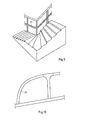
Fig. 4 inklusive Biegeform und Biegedorn, - Fig. 6
- eine schematische Draufsicht einer erfindungsgemäßen Profilbiegemaschine umfassend ein Ausführungsbeispiel einer erfindungsgemäßen Vorrichtung,
- Fig. 7a) bis
- d) in einer perspektivischen, schematischen Darstellung ein Ausführungsbeispiel des erfindungsgemäßen Verfahrens zu verschiedenen Zeitpunkten unter Verwendung der Vorrichtung aus
Fig. 5 , - Fig. 8
- in einer perspektivischen, schematischen Darstellung ein hergestelltes, gebogenes Hohlprofil mit tordierter Ausformung,
- Fig. 9
- in einer schematischen, perspektivischen Darstellung ein Stuhlführungsprofil eines Treppenlifts in einem Treppenhaus und
- Fig. 10
- eine schematische Darstellung einer A-Säule eines Kraftfahrzeugs.
- Fig. 1
- FIG. 2 is a schematic plan view of the annular gap outlet of an embodiment of an annular gap tool, FIG.
- Fig. 2
- the annular gap tool
Fig. 1 in a perspective view, - Fig. 3
- 3 is a cross-sectional view of a comparison between the cross-sectional shape of a hollow-section blank according to a further exemplary embodiment and the formed hollow profile blank with at least one longitudinally oriented formation,
- Fig. 4
- the embodiment of an annular gap tool
Fig. 1 with upstream guide sleeve and mandrel shaft according to a further embodiment of the annular gap tool in an axial, schematic sectional view, - Fig. 5
- in a perspective, schematic view of the embodiment
Fig. 4 including bending form and bending mandrel, - Fig. 6
- a schematic plan view of a profile bending machine according to the invention comprising an embodiment of a device according to the invention,
- Fig. 7a) to
- d) in a perspective, schematic representation of an embodiment of the inventive method at different times using the device from
Fig. 5 . - Fig. 8
- in a perspective, schematic representation of a manufactured, curved hollow profile with twisted shape,
- Fig. 9
- in a schematic, perspective view of a chair guide profile of a stair lift in a staircase and
- Fig. 10
- a schematic representation of an A-pillar of a motor vehicle.
Im Vergleich zu dem bisher bekannten Stand der Technik, bei welchem über eine schraubenförmige Nute aufweisendes inneres Gesenk eine lageveränderliche, insbesondere tordierte Ausformung in ein Hohlprofil eingebracht wird, wie dies beispielsweise in der Patentschrift
Im Unterschied zu dem bekannten Stand der Technik ist das dargestellte Ausführungsbeispiel eines Ringspaltwerkzeugs deutlich einfacher aufgebaut und kann weichere Formübergänge aufweisen, so dass eine Umformung eines Hohlprofilrohlings zu einem Hohlprofil mit lageveränderlichen, längsorientierten Ausformungen auf einfache Weise und ohne große Umformkräfte erfolgen kann. Insbesondere ist es mit dem erfindungsgemäßen Verfahren und der Vorrichtung möglich, die Steigung der längsorientierten, lageveränderlichen Ausformung ("Windungen") über die zeitlich variierende Rotation des äußeren Gesenks aktiv zu steuern.In contrast to the known prior art, the illustrated embodiment of an annular gap tool is constructed much simpler and can softer shape transitions have, so that a transformation of a hollow section blank to a hollow profile with variable position, longitudinally oriented formations can be done in a simple manner and without large forming forces. In particular, it is possible with the method and apparatus according to the invention to actively control the pitch of the longitudinally oriented, variable-position formation ("turns") via the time-varying rotation of the outer die.
Vorzugsweise ändert sich während der Umformung des Hohlprofilrohlings mit dem Ringspaltwerkzeug 1 der Umfang des Hohlprofilrohlings nicht. Hieraus ergibt sich, dass die Länge der neutralen Faser, d.h. die Mittellinie der Blechdicke des Hohlprofilrohlings sich gar nicht oder nur in engen Grenzen vorzugsweise +/- 25% oder besonders bevorzugt +/- 15% ändert. Die in Blechebene stattfindende Umformarbeit wird hierdurch minimiert, so dass die Umformkräfte weiter reduziert werden können.Preferably, during the deformation of the hollow profile blank with the
Die in
Um nun ein gebogenes Hohlprofil mit lageveränderlichen, längsorientierten Ausformungen herzustellen, wird das in den
Wie der Pfeil andeutet, kann die Profilvorschubeinheit 15 eine translatorische Bewegung durchführen, um den Hohlprofilrohling 16 möglichst kontinuierlich relativ zum und durch das Ringspaltwerkzeug 1 zu bewegen bzw. zu führen. Darüber hinaus wird der umgeformte Hohlprofilrohling 16 weiter in Richtung Biegeform 11 und den Biegedorn 12 verschoben und mit eingebrachter, lageveränderlicher, längsorientierter Ausformung gebogen. Zusätzlich dargestellt sind in
Der Winkel α kann in beliebige Richtungen senkrecht zur Axialachse des Ringspaltwerkzeugs eingestellt werden. Wie mit den Pfeilen am Ringspaltwerkzeug 1 sowie an der Biegeform 11 angedeutet, dreht sich die Biegeform 11 mit dem Ringspaltwerkzeug 1 synchron mit, so dass die Biegeform 11 jeweils den in das Hohlprofil eingebrachte Ausformungen folgen kann. In
Die Mittel zur Durchführung einer relativen Drehung um die Axialachse des Ringspaltwerkzeugs, der Biegeform gegenüber dem Hohlprofilrohling sind in
Vorzugsweise ist die soeben beschriebene Vorrichtung auf einer Profilbiegemaschine 19 angeordnet,
Zusätzlich zur Stützung der Führung des Hohlprofilrohlings 16 sind in
Die einzelnen Verfahrensschritte sind in
Wird die Biegeform 11 nun in ihrem Winkel α zur Axialachse des Hohlprofilrohlings 16 bzw. des Ringspaltwerkzeugs 1 verändert, so führt dies, wie in 
mit z(t): Profilvorschub in Axialrichtung.If the bending
with z (t): profile feed in the axial direction.
Mit dieser Funktion kann die Relativdrehung des äußeren Gesenks gesteuert werden, um den gewünschten Verlauf der Ausformungen im Hohlprofil zu erhalten.With this function, the relative rotation of the outer die can be controlled to obtain the desired course of the formations in the hollow profile.
Ein gebogenes Hohlprofil mit lageveränderlichen, längsorientierten Ausnehmungen 23 zeigt
Claims (15)
dadurch gekennzeichnet, dass das am Formgebungswerkzeug austretende umgeformte Profil-oder Hohlprofil unter Verwendung einer nachgeordneten Biegeform (11) mit einem optionalen Biegdorn (12) gebogen wird.Method according to claim 1,
characterized in that the forming tool exiting reshaped profile or hollow profile using a downstream Bending mold (11) with an optional bending mandrel (12) is bent.
dadurch gekennzeichnet, dass folgende Verfahrensschritte umfasst sind:
characterized in that the following method steps are included:
dadurch gekennzeichnet, dass der Hohlprofilrohling (16) in einem Einlaufbereich (5a) des Ringspalteingangs (5) und/oder in einem Auslaufbereich (6a) am Ringspaltausgang (6) während der Relativbewegung in seiner Form nicht geändert wird.Method according to claim 3,
characterized in that the hollow profile blank (16) in an inlet region (5a) of the annular gap inlet (5) and / or in an outlet region (6a) at the annular gap outlet (6) is not changed in its shape during the relative movement.
dadurch gekennzeichnet, dass die Relativbewegung zwischen Profil- oder Hohlprofilrohling (16) und dem Formggebungswerkzeug (1) und der Biegeform (11) durch Vorschieben des Profil- oder Hohlprofilrohlings (16) unter Verwendung einer Profilvorschubeinheit (15) durchgeführt wird.Method according to claims 1 to 4,
characterized in that the relative movement between profile or hollow profile blank (16) and the forming mold (1) and the bending mold (11) by advancing the profile or hollow profile blank (16) using a profile feed unit (15) is performed.
dadurch gekennzeichnet, dass der Profil- oder Hohlprofilrohling (16) während des Profilvorschubs, optional unter Verwendung der Profilvorschubeinheit (15), gedreht wird.Method according to claim 5,
characterized in that the profile or hollow profile blank (16) during the Profile feed, optionally using the profile feed unit (15) is rotated.
dadurch gekennzeichnet, dass der Profil- oder Hohlprofilrohling (16) unter Verwendung einer Führungshülse (9) und eines inneren Dornschafts (10) während der Relativbewegung von Profil oder Hohlprofilrohling (16) und Formgebungswerkzeug (1) geführt wird.Method according to one of claims 1 to 6,
characterized in that the profile or hollow profile blank (16) using a guide sleeve (9) and an inner mandrel shaft (10) during the relative movement of profile or hollow profile blank (16) and shaping tool (1) is guided.
dadurch gekennzeichnet, dass das hergestellte Profil oder Hohlprofil Teil einer Fahrzeugkarosserie, eine A-Säule (25) mit anschließenden Dachrahmen eines Kraftfahrzeugs oder ein Profil oder Hohlprofil einer Treppenlift-Stuhlführung (24) ist.Method according to one of claims 1 to 7,
characterized in that the profile or hollow profile produced part of a vehicle body, an A-pillar (25) with adjoining roof frame of a motor vehicle or a profile or hollow profile of a stairlift chair guide (24).
dadurch gekennzeichnet, dass am Ausgang des Formgebungswerkzeugs eine Biegeform (11) mit einem optionalen Biegedorn (12) vorgesehen ist.Device according to claim 9,
characterized in that at the output of the forming tool, a bending mold (11) with an optional bending mandrel (12) is provided.
dadurch gekennzeichnet, dass die Vorrichtung umfasst
characterized in that the device comprises
dadurch gekennzeichnet, dass die Biegeform (11) derart angeordnet ist, dass der Winkel (α) zwischen der Axialachse der Biegeform (11) und der Axialachse des Formgebungswerkzeugs (1) zur Veränderung des Krümmungsradius des Profils oder Hohlprofils vor, nach und/oder während des Umformens variabel einstellbar ist.Device according to one of claims 10 or 11,
characterized in that the bending mold (11) is arranged such that the angle (α) between the axial axis of the bending mold (11) and the axial axis of the forming tool (1) for changing the radius of curvature of the profile or hollow profile before, after and / or during of the forming is variably adjustable.
dadurch gekennzeichnet, dass das äußere Gesenk (2) des Ringspaltwerkzeugs (1) und/oder die Biegeform (11) einen Antrieb zur axialen Drehung aufweisen.Device according to one of claims 9 to 12,
characterized in that the outer die (2) of the annular gap tool (1) and / or the bending mold (11) have a drive for axial rotation.
dadurch gekennzeichnet, dass eine Führungshülse (9) und ein Dornschaft (10) zur Führung des Hohlprofilrohlings (16) vor dem Formgebungswerkzeug (1) angeordnet sind, wobei optional das innere Gesenk (3) des Ringspaltwerkzeugs (1) frei drehbar am Dornschaft (10) befestigt ist.Device according to one of claims 9 to 13,
characterized in that a guide sleeve (9) and a mandrel shaft (10) for guiding the hollow profile blank (16) in front of the forming tool (1) are arranged, wherein optionally the inner die (3) of the annular gap tool (1) freely rotatably on the mandrel shaft (10 ) is attached.
dadurch gekennzeichnet, dass das Formgebungswerkzeug (1), die Biegeform (11) mit optionalem Biegedorn (12), die Mittel (15) zur Durchführung der Relativbewegung zwischen Profil- oder Hohlprofilrohling (16) und Formgebungswerkzeug (1), die Mittel (18) zur Drehung des Formgebungswerkzeugs und optional eine Profilvorschubeinheit (15) sowie eine Führungshülse (9) auf einer Profilbiegemaschine (19) angeordnet sind.Device according to one of claims 10 to 14,
characterized in that the forming tool (1), the bending mold (11) with optional bending mandrel (12), the means (15) for carrying out the relative movement between profile or hollow profile blank (16) and forming tool (1), the means (18) for rotation of the forming tool and optionally a profile feed unit (15) and a guide sleeve (9) on a profile bending machine (19) are arranged.
Priority Applications (4)
| Application Number | Priority Date | Filing Date | Title |
|---|---|---|---|
| EP11189248.5A EP2594346A1 (en) | 2011-11-15 | 2011-11-15 | Device and method for manufacturing profiles with form that have variable position and are oriented in the length direction |
| EP12787719.9A EP2780126B1 (en) | 2011-11-15 | 2012-11-15 | Device and method for manufacturing profiles with shape that is variable according to the position and is oriented in the length direction |
| ES12787719.9T ES2577835T3 (en) | 2011-11-15 | 2012-11-15 | Procedure and device for manufacturing profiles with variable position formation, oriented longitudinally |
| PCT/EP2012/072728 WO2013072414A1 (en) | 2011-11-15 | 2012-11-15 | Method and device for producing profiled elements with a positionally adjustable, longitudinally-oriented shaped section |
Applications Claiming Priority (1)
| Application Number | Priority Date | Filing Date | Title |
|---|---|---|---|
| EP11189248.5A EP2594346A1 (en) | 2011-11-15 | 2011-11-15 | Device and method for manufacturing profiles with form that have variable position and are oriented in the length direction |
Publications (1)
| Publication Number | Publication Date |
|---|---|
| EP2594346A1 true EP2594346A1 (en) | 2013-05-22 |
Family
ID=47191754
Family Applications (2)
| Application Number | Title | Priority Date | Filing Date |
|---|---|---|---|
| EP11189248.5A Withdrawn EP2594346A1 (en) | 2011-11-15 | 2011-11-15 | Device and method for manufacturing profiles with form that have variable position and are oriented in the length direction |
| EP12787719.9A Active EP2780126B1 (en) | 2011-11-15 | 2012-11-15 | Device and method for manufacturing profiles with shape that is variable according to the position and is oriented in the length direction |
Family Applications After (1)
| Application Number | Title | Priority Date | Filing Date |
|---|---|---|---|
| EP12787719.9A Active EP2780126B1 (en) | 2011-11-15 | 2012-11-15 | Device and method for manufacturing profiles with shape that is variable according to the position and is oriented in the length direction |
Country Status (3)
| Country | Link |
|---|---|
| EP (2) | EP2594346A1 (en) |
| ES (1) | ES2577835T3 (en) |
| WO (1) | WO2013072414A1 (en) |
Cited By (1)
| Publication number | Priority date | Publication date | Assignee | Title |
|---|---|---|---|---|
| CN104259277A (en) * | 2014-09-22 | 2015-01-07 | 倪慨宇 | Plastic constraint component for bending thin wall profile material |
Citations (4)
| Publication number | Priority date | Publication date | Assignee | Title |
|---|---|---|---|---|
| DE3807002C1 (en) | 1988-03-01 | 1989-04-27 | Mannesmann Ag, 4000 Duesseldorf, De | |
| DE4428827A1 (en) * | 1994-08-17 | 1996-03-14 | Kleiner Matthias Prof Dr Ing H | Process for the production of curved workpieces by a combination of extrusion and bending |
| EP1863604A2 (en) * | 2005-03-22 | 2007-12-12 | ThyssenKrupp Steel AG | Device for the free forming and bending of longitudinal profiles, particularly pipes, and a combined device for free forming and bending as well as draw-bending longitudinal profiles, particularly pipes |
| EP2266720A2 (en) * | 2009-06-17 | 2010-12-29 | ThyssenKrupp Steel Europe AG | Device and method for free bending of profiles |
-
2011
- 2011-11-15 EP EP11189248.5A patent/EP2594346A1/en not_active Withdrawn
-
2012
- 2012-11-15 ES ES12787719.9T patent/ES2577835T3/en active Active
- 2012-11-15 EP EP12787719.9A patent/EP2780126B1/en active Active
- 2012-11-15 WO PCT/EP2012/072728 patent/WO2013072414A1/en active Application Filing
Patent Citations (5)
| Publication number | Priority date | Publication date | Assignee | Title |
|---|---|---|---|---|
| DE3807002C1 (en) | 1988-03-01 | 1989-04-27 | Mannesmann Ag, 4000 Duesseldorf, De | |
| DE4428827A1 (en) * | 1994-08-17 | 1996-03-14 | Kleiner Matthias Prof Dr Ing H | Process for the production of curved workpieces by a combination of extrusion and bending |
| EP1863604A2 (en) * | 2005-03-22 | 2007-12-12 | ThyssenKrupp Steel AG | Device for the free forming and bending of longitudinal profiles, particularly pipes, and a combined device for free forming and bending as well as draw-bending longitudinal profiles, particularly pipes |
| EP1863604B1 (en) | 2005-03-22 | 2009-08-19 | ThyssenKrupp Steel AG | Device for the free forming and bending of longitudinal profiles, particularly pipes, and a combined device for free forming and bending as well as draw-bending longitudinal profiles, particularly pipes |
| EP2266720A2 (en) * | 2009-06-17 | 2010-12-29 | ThyssenKrupp Steel Europe AG | Device and method for free bending of profiles |
Cited By (2)
| Publication number | Priority date | Publication date | Assignee | Title |
|---|---|---|---|---|
| CN104259277A (en) * | 2014-09-22 | 2015-01-07 | 倪慨宇 | Plastic constraint component for bending thin wall profile material |
| CN104259277B (en) * | 2014-09-22 | 2017-06-30 | 倪慨宇 | A kind of plastic constraint component for bending thin-wall section |
Also Published As
| Publication number | Publication date |
|---|---|
| ES2577835T3 (en) | 2016-07-19 |
| EP2780126A1 (en) | 2014-09-24 |
| WO2013072414A1 (en) | 2013-05-23 |
| EP2780126B1 (en) | 2016-04-13 |
Similar Documents
| Publication | Publication Date | Title |
|---|---|---|
| EP3206811B1 (en) | Method for producing a profiled hollow shaft for a telescopic steering shaft of a motor vehicle | |
| EP1863604B1 (en) | Device for the free forming and bending of longitudinal profiles, particularly pipes, and a combined device for free forming and bending as well as draw-bending longitudinal profiles, particularly pipes | |
| WO2016082969A1 (en) | Method for producing a profiled hollow shaft for a telescopic steering shaft and telescopic steering shaft | |
| EP1954420B1 (en) | Method and device for the coreless forming of hollow profiles | |
| EP2641673B1 (en) | Method and apparatus for producing a connecting section as part of a tool | |
| DE102009025988A1 (en) | Device and method for free-form bending of profiles | |
| EP3645188A1 (en) | Method for producing a bent part and bending machine for performing the method | |
| DE2642743B2 (en) | Device for manufacturing a motor vehicle axle | |
| EP0546319A1 (en) | Stretch bending method for bending hollow profiles and mandrel stretch bending machine | |
| DE102005031437A1 (en) | Method for producing strip profiles by pulling through dies with pivot mounted adjustable outer sections | |
| DE2319819A1 (en) | METHOD AND MOLDING MACHINE FOR THE PRODUCTION OF PROFILE PIECES FROM SHEET METAL STRIPS | |
| EP2380674A2 (en) | Expandable bending head | |
| EP2780126B1 (en) | Device and method for manufacturing profiles with shape that is variable according to the position and is oriented in the length direction | |
| DE102006052794A1 (en) | Method for bending metallic profiles, involves supplying one or more bending tools by bending profile toward its longitudinal axis | |
| WO2019238430A1 (en) | Cold rolling machine and method for producing a profile on a workpiece | |
| DE19905038B4 (en) | Spine device, cross rolling device and method for producing cross-rolled, at least partially hollow body | |
| EP1914021B1 (en) | Device for bending bars and/or rod shaped workpieces, in particular pipes, and bending tool for this device | |
| EP2419227B1 (en) | Bending press for sheet panels | |
| DE10311144B3 (en) | Method for producing a tube with an internal profile and device for carrying out the method | |
| DE102008006293A1 (en) | Method and device for bending round tubes and profiles | |
| DE19754171B4 (en) | Method for producing a profile with a cross-section which changes in its longitudinal direction and apparatus for carrying out the method | |
| DE102006053518A1 (en) | Two/three-dimensional bent profile e.g. u-profile, strip-winding method for building industry, involves guiding profiles under forces by window, where window has bars, which are penetrated in to cross section and guided to volume changes | |
| EP2121208B1 (en) | Method and device for rolling a product to be rolled in a rolling mill having a cross-rolling mill | |
| DE947587C (en) | Process and device for the non-cutting manufacture of blades for flow machines | |
| EP4323132A1 (en) | Method for producing a component which has a toothing profile, and tool device |
Legal Events
| Date | Code | Title | Description |
|---|---|---|---|
| PUAI | Public reference made under article 153(3) epc to a published international application that has entered the european phase |
Free format text: ORIGINAL CODE: 0009012 |
|
| AK | Designated contracting states |
Kind code of ref document: A1 Designated state(s): AL AT BE BG CH CY CZ DE DK EE ES FI FR GB GR HR HU IE IS IT LI LT LU LV MC MK MT NL NO PL PT RO RS SE SI SK SM TR |
|
| AX | Request for extension of the european patent |
Extension state: BA ME |
|
| RIN1 | Information on inventor provided before grant (corrected) |
Inventor name: VAN DER HEIDEN, ARNOLDUS THEODORUS Inventor name: FLEHMIG, THOMAS Inventor name: MULDER, GIJS J.J. Inventor name: KIBBEN, MARTIN Inventor name: DE GRAAF, MATTIJN G. Inventor name: DE JONG, ROLF BERNHARD Inventor name: MERTENS, OLIVER |
|
| STAA | Information on the status of an ep patent application or granted ep patent |
Free format text: STATUS: THE APPLICATION IS DEEMED TO BE WITHDRAWN |
|
| 18D | Application deemed to be withdrawn |
Effective date: 20131123 |