EP2593783B1 - Ultraschallsignal analyse mit hilfe eines dynamischen datenverarbeitungsfensters zur früherkennung von verkalkung in wasserbehandlunggeräten - Google Patents
Ultraschallsignal analyse mit hilfe eines dynamischen datenverarbeitungsfensters zur früherkennung von verkalkung in wasserbehandlunggeräten Download PDFInfo
- Publication number
- EP2593783B1 EP2593783B1 EP11754921.2A EP11754921A EP2593783B1 EP 2593783 B1 EP2593783 B1 EP 2593783B1 EP 11754921 A EP11754921 A EP 11754921A EP 2593783 B1 EP2593783 B1 EP 2593783B1
- Authority
- EP
- European Patent Office
- Prior art keywords
- time
- scaling
- port
- trend line
- moving average
- Prior art date
- Legal status (The legal status is an assumption and is not a legal conclusion. Google has not performed a legal analysis and makes no representation as to the accuracy of the status listed.)
- Not-in-force
Links
- XLYOFNOQVPJJNP-UHFFFAOYSA-N water Substances O XLYOFNOQVPJJNP-UHFFFAOYSA-N 0.000 title claims description 28
- 238000012545 processing Methods 0.000 title claims description 25
- 238000001514 detection method Methods 0.000 title claims description 7
- 239000012528 membrane Substances 0.000 claims description 45
- 238000000034 method Methods 0.000 claims description 38
- 238000009826 distribution Methods 0.000 claims description 13
- 230000003204 osmotic effect Effects 0.000 claims description 10
- 238000001223 reverse osmosis Methods 0.000 claims description 10
- 238000011010 flushing procedure Methods 0.000 claims description 8
- 239000000126 substance Substances 0.000 claims description 5
- 238000004140 cleaning Methods 0.000 claims description 4
- 238000012544 monitoring process Methods 0.000 claims description 4
- 230000003595 spectral effect Effects 0.000 claims description 3
- -1 heat exchangers Substances 0.000 claims description 2
- 238000001728 nano-filtration Methods 0.000 claims description 2
- 238000000108 ultra-filtration Methods 0.000 claims description 2
- 229920006395 saturated elastomer Polymers 0.000 claims 2
- 238000012360 testing method Methods 0.000 description 50
- 239000012466 permeate Substances 0.000 description 42
- 230000007423 decrease Effects 0.000 description 22
- 238000002474 experimental method Methods 0.000 description 21
- 230000008859 change Effects 0.000 description 15
- 239000000243 solution Substances 0.000 description 12
- 230000004907 flux Effects 0.000 description 11
- 230000008569 process Effects 0.000 description 11
- 230000003247 decreasing effect Effects 0.000 description 10
- 230000006870 function Effects 0.000 description 10
- 238000001228 spectrum Methods 0.000 description 10
- 238000011144 upstream manufacturing Methods 0.000 description 10
- OSGAYBCDTDRGGQ-UHFFFAOYSA-L calcium sulfate Chemical compound [Ca+2].[O-]S([O-])(=O)=O OSGAYBCDTDRGGQ-UHFFFAOYSA-L 0.000 description 9
- 150000003839 salts Chemical class 0.000 description 9
- 239000012527 feed solution Substances 0.000 description 8
- 238000013459 approach Methods 0.000 description 7
- 238000005259 measurement Methods 0.000 description 7
- VTYYLEPIZMXCLO-UHFFFAOYSA-L Calcium carbonate Chemical compound [Ca+2].[O-]C([O-])=O VTYYLEPIZMXCLO-UHFFFAOYSA-L 0.000 description 6
- 238000011534 incubation Methods 0.000 description 6
- 230000004044 response Effects 0.000 description 6
- 239000012266 salt solution Substances 0.000 description 6
- 238000005070 sampling Methods 0.000 description 6
- 238000004458 analytical method Methods 0.000 description 5
- 239000012530 fluid Substances 0.000 description 5
- 239000004417 polycarbonate Substances 0.000 description 5
- UIIMBOGNXHQVGW-UHFFFAOYSA-M Sodium bicarbonate Chemical compound [Na+].OC([O-])=O UIIMBOGNXHQVGW-UHFFFAOYSA-M 0.000 description 4
- 238000004422 calculation algorithm Methods 0.000 description 4
- 238000010612 desalination reaction Methods 0.000 description 4
- 230000000694 effects Effects 0.000 description 4
- 238000010191 image analysis Methods 0.000 description 4
- 230000000670 limiting effect Effects 0.000 description 4
- 230000035945 sensitivity Effects 0.000 description 4
- 230000001960 triggered effect Effects 0.000 description 4
- OYPRJOBELJOOCE-UHFFFAOYSA-N Calcium Chemical compound [Ca] OYPRJOBELJOOCE-UHFFFAOYSA-N 0.000 description 3
- 229910052791 calcium Inorganic materials 0.000 description 3
- 239000011575 calcium Substances 0.000 description 3
- 229910000019 calcium carbonate Inorganic materials 0.000 description 3
- 238000012937 correction Methods 0.000 description 3
- 238000010586 diagram Methods 0.000 description 3
- 238000002149 energy-dispersive X-ray emission spectroscopy Methods 0.000 description 3
- 230000006698 induction Effects 0.000 description 3
- 238000001000 micrograph Methods 0.000 description 3
- 238000000386 microscopy Methods 0.000 description 3
- 230000003449 preventive effect Effects 0.000 description 3
- 239000012465 retentate Substances 0.000 description 3
- 230000002441 reversible effect Effects 0.000 description 3
- 238000003860 storage Methods 0.000 description 3
- 238000012546 transfer Methods 0.000 description 3
- 229910021532 Calcite Inorganic materials 0.000 description 2
- UXVMQQNJUSDDNG-UHFFFAOYSA-L Calcium chloride Chemical compound [Cl-].[Cl-].[Ca+2] UXVMQQNJUSDDNG-UHFFFAOYSA-L 0.000 description 2
- CURLTUGMZLYLDI-UHFFFAOYSA-N Carbon dioxide Chemical compound O=C=O CURLTUGMZLYLDI-UHFFFAOYSA-N 0.000 description 2
- KFZMGEQAYNKOFK-UHFFFAOYSA-N Isopropanol Chemical compound CC(C)O KFZMGEQAYNKOFK-UHFFFAOYSA-N 0.000 description 2
- VYPSYNLAJGMNEJ-UHFFFAOYSA-N Silicium dioxide Chemical compound O=[Si]=O VYPSYNLAJGMNEJ-UHFFFAOYSA-N 0.000 description 2
- XAGFODPZIPBFFR-UHFFFAOYSA-N aluminium Chemical compound [Al] XAGFODPZIPBFFR-UHFFFAOYSA-N 0.000 description 2
- 229910052782 aluminium Inorganic materials 0.000 description 2
- 230000008901 benefit Effects 0.000 description 2
- 239000001110 calcium chloride Substances 0.000 description 2
- 229910001628 calcium chloride Inorganic materials 0.000 description 2
- 238000004364 calculation method Methods 0.000 description 2
- 238000005056 compaction Methods 0.000 description 2
- 238000012790 confirmation Methods 0.000 description 2
- 238000001816 cooling Methods 0.000 description 2
- 238000004442 gravimetric analysis Methods 0.000 description 2
- 239000000463 material Substances 0.000 description 2
- 238000012986 modification Methods 0.000 description 2
- 230000004048 modification Effects 0.000 description 2
- 230000003287 optical effect Effects 0.000 description 2
- 230000010287 polarization Effects 0.000 description 2
- 229910000030 sodium bicarbonate Inorganic materials 0.000 description 2
- 238000007619 statistical method Methods 0.000 description 2
- 230000002277 temperature effect Effects 0.000 description 2
- 238000002604 ultrasonography Methods 0.000 description 2
- 238000009825 accumulation Methods 0.000 description 1
- 230000009471 action Effects 0.000 description 1
- 239000007864 aqueous solution Substances 0.000 description 1
- 229910052788 barium Inorganic materials 0.000 description 1
- DSAJWYNOEDNPEQ-UHFFFAOYSA-N barium atom Chemical compound [Ba] DSAJWYNOEDNPEQ-UHFFFAOYSA-N 0.000 description 1
- 238000011021 bench scale process Methods 0.000 description 1
- 230000033228 biological regulation Effects 0.000 description 1
- 230000005540 biological transmission Effects 0.000 description 1
- 239000012267 brine Substances 0.000 description 1
- 230000005587 bubbling Effects 0.000 description 1
- WUKWITHWXAAZEY-UHFFFAOYSA-L calcium difluoride Chemical compound [F-].[F-].[Ca+2] WUKWITHWXAAZEY-UHFFFAOYSA-L 0.000 description 1
- 229910001634 calcium fluoride Inorganic materials 0.000 description 1
- BVKZGUZCCUSVTD-UHFFFAOYSA-N carbonic acid Chemical compound OC(O)=O BVKZGUZCCUSVTD-UHFFFAOYSA-N 0.000 description 1
- 238000012512 characterization method Methods 0.000 description 1
- 238000012993 chemical processing Methods 0.000 description 1
- 238000006243 chemical reaction Methods 0.000 description 1
- 239000002131 composite material Substances 0.000 description 1
- 239000012141 concentrate Substances 0.000 description 1
- 230000008878 coupling Effects 0.000 description 1
- 238000010168 coupling process Methods 0.000 description 1
- 238000005859 coupling reaction Methods 0.000 description 1
- 239000013078 crystal Substances 0.000 description 1
- 230000001186 cumulative effect Effects 0.000 description 1
- 238000013480 data collection Methods 0.000 description 1
- 230000007547 defect Effects 0.000 description 1
- 238000013461 design Methods 0.000 description 1
- 238000006073 displacement reaction Methods 0.000 description 1
- 238000001914 filtration Methods 0.000 description 1
- 239000011888 foil Substances 0.000 description 1
- 238000010438 heat treatment Methods 0.000 description 1
- 238000013383 initial experiment Methods 0.000 description 1
- 238000002347 injection Methods 0.000 description 1
- 239000007924 injection Substances 0.000 description 1
- 229910052500 inorganic mineral Inorganic materials 0.000 description 1
- 238000007689 inspection Methods 0.000 description 1
- 230000002427 irreversible effect Effects 0.000 description 1
- 238000004519 manufacturing process Methods 0.000 description 1
- 238000013507 mapping Methods 0.000 description 1
- 239000003550 marker Substances 0.000 description 1
- 239000011707 mineral Substances 0.000 description 1
- 235000010755 mineral Nutrition 0.000 description 1
- 230000000116 mitigating effect Effects 0.000 description 1
- 239000000203 mixture Substances 0.000 description 1
- 230000006911 nucleation Effects 0.000 description 1
- 238000010899 nucleation Methods 0.000 description 1
- 230000036961 partial effect Effects 0.000 description 1
- 230000035699 permeability Effects 0.000 description 1
- 239000004033 plastic Substances 0.000 description 1
- 229920002647 polyamide Polymers 0.000 description 1
- 229920000515 polycarbonate Polymers 0.000 description 1
- 239000002244 precipitate Substances 0.000 description 1
- 238000001556 precipitation Methods 0.000 description 1
- 238000011045 prefiltration Methods 0.000 description 1
- 239000000047 product Substances 0.000 description 1
- 238000010223 real-time analysis Methods 0.000 description 1
- 230000002829 reductive effect Effects 0.000 description 1
- 238000002310 reflectometry Methods 0.000 description 1
- 230000008439 repair process Effects 0.000 description 1
- 239000000377 silicon dioxide Substances 0.000 description 1
- 238000002791 soaking Methods 0.000 description 1
- 235000017557 sodium bicarbonate Nutrition 0.000 description 1
- HPALAKNZSZLMCH-UHFFFAOYSA-M sodium;chloride;hydrate Chemical compound O.[Na+].[Cl-] HPALAKNZSZLMCH-UHFFFAOYSA-M 0.000 description 1
- 239000007787 solid Substances 0.000 description 1
- 229910001220 stainless steel Inorganic materials 0.000 description 1
- 239000010935 stainless steel Substances 0.000 description 1
- 238000010972 statistical evaluation Methods 0.000 description 1
- 238000003756 stirring Methods 0.000 description 1
- 229910052712 strontium Inorganic materials 0.000 description 1
- CIOAGBVUUVVLOB-UHFFFAOYSA-N strontium atom Chemical compound [Sr] CIOAGBVUUVVLOB-UHFFFAOYSA-N 0.000 description 1
- 150000003467 sulfuric acid derivatives Chemical class 0.000 description 1
- 238000005211 surface analysis Methods 0.000 description 1
- 230000009897 systematic effect Effects 0.000 description 1
- 238000003466 welding Methods 0.000 description 1
- 238000009736 wetting Methods 0.000 description 1
Images





Classifications
-
- G—PHYSICS
- G01—MEASURING; TESTING
- G01N—INVESTIGATING OR ANALYSING MATERIALS BY DETERMINING THEIR CHEMICAL OR PHYSICAL PROPERTIES
- G01N29/00—Investigating or analysing materials by the use of ultrasonic, sonic or infrasonic waves; Visualisation of the interior of objects by transmitting ultrasonic or sonic waves through the object
- G01N29/02—Analysing fluids
-
- G—PHYSICS
- G01—MEASURING; TESTING
- G01N—INVESTIGATING OR ANALYSING MATERIALS BY DETERMINING THEIR CHEMICAL OR PHYSICAL PROPERTIES
- G01N29/00—Investigating or analysing materials by the use of ultrasonic, sonic or infrasonic waves; Visualisation of the interior of objects by transmitting ultrasonic or sonic waves through the object
- G01N29/02—Analysing fluids
- G01N29/032—Analysing fluids by measuring attenuation of acoustic waves
-
- G—PHYSICS
- G01—MEASURING; TESTING
- G01N—INVESTIGATING OR ANALYSING MATERIALS BY DETERMINING THEIR CHEMICAL OR PHYSICAL PROPERTIES
- G01N2291/00—Indexing codes associated with group G01N29/00
- G01N2291/02—Indexing codes associated with the analysed material
- G01N2291/024—Mixtures
- G01N2291/02491—Materials with nonlinear acoustic properties
-
- G—PHYSICS
- G01—MEASURING; TESTING
- G01N—INVESTIGATING OR ANALYSING MATERIALS BY DETERMINING THEIR CHEMICAL OR PHYSICAL PROPERTIES
- G01N2291/00—Indexing codes associated with group G01N29/00
- G01N2291/02—Indexing codes associated with the analysed material
- G01N2291/025—Change of phase or condition
- G01N2291/0258—Structural degradation, e.g. fatigue of composites, ageing of oils
-
- G—PHYSICS
- G01—MEASURING; TESTING
- G01N—INVESTIGATING OR ANALYSING MATERIALS BY DETERMINING THEIR CHEMICAL OR PHYSICAL PROPERTIES
- G01N2291/00—Indexing codes associated with group G01N29/00
- G01N2291/02—Indexing codes associated with the analysed material
- G01N2291/028—Material parameters
- G01N2291/02836—Flow rate, liquid level
-
- G—PHYSICS
- G01—MEASURING; TESTING
- G01N—INVESTIGATING OR ANALYSING MATERIALS BY DETERMINING THEIR CHEMICAL OR PHYSICAL PROPERTIES
- G01N2291/00—Indexing codes associated with group G01N29/00
- G01N2291/26—Scanned objects
- G01N2291/263—Surfaces
- G01N2291/2634—Surfaces cylindrical from outside
Definitions
- the present invention relates to water processing systems and more particularly, to an early detection of scaling processes in such systems, using statistical methods.
- the scaling referred to herein is the precipitation of sparingly soluble salts (including but not limited to sulfates of calcium, barium and strontium, calcium carbonate, silica and calcium fluoride) on the internal surfaces of these conduits due to the creation of supersaturation conditions on these internal surfaces by temperature or concentration gradients.
- sparingly soluble salts including but not limited to sulfates of calcium, barium and strontium, calcium carbonate, silica and calcium fluoride
- sparingly soluble salts usually have an induction time between the time that supersaturated conditions are obtained and the time that scaling of internal surfaces begins, one can take preventive actions just before, or at the end, of such an induction time by a variety of approaches.
- One example is the use of osmotic flushing to periodically sweep away supersaturated solutions and other foulants in reverse osmosis (RO) processes.
- Another example is the use of blowdown in cooling towers and flushing of heat exchangers with undersaturated solutions.
- Another solution is the use of flow reversal to replace supersaturated concentrate solution with undersaturated feed solution next to a desalination membrane. The problem is that if the early warning is too early and sensitive, then the preventative treatment sequence can be too frequent resulting in unnecessary use of chemicals, loss of production, or wear of equipment.
- Another option is to use devices that do allow sampling of the conditions of the internal surfaces of an opaque conduit containing water processing equipment.
- a well known example is the use of ultrasound, which is used for detecting defects in welding in pipes and leaks inside conduits in the chemical-processing industry.
- a known method detects the presence of mineral deposits on water treatment membrane surfaces in both opaque flat sheet and commercial spiral wound pressure vessels, see for instance Mairal et al., Real-time measurement of inorganic fouling of RO desalination membranes using ultrasonic time-domain reflectometry, Journal of Membrane Science 159 (1999) 185-196 .
- the present invention in embodiments thereof, overcomes the drawbacks of the prior art by providing a method of detecting pre-conditions of scaling, potentially occurring in conduits of water processing equipment.
- water processing equipment may include reverse osmosis, nanofiltration, ultrafiltration membranes, heat exchangers, and water transport pipelines.
- the system includes one or more ultrasonic transceivers that may each include a transmitter and a receiver.
- the transceivers are configured to transmit one or more ultrasonic signals through the walls of the conduits, and receive the ultrasonic signals and/or reflections thereof.
- the system further includes a sampler configured to sample in real-time, data samples indicative of spectral parameters, from received ultrasonic signals or reflections thereof.
- the system further includes a processing unit, possibly implemented as a computer. The processing unit is configured to:
- the system may further include a control module configured to issue an alert upon the detection of a crossover.
- the control unit may further be configured to apply an intervention to the water processing equipment such that the scaling is avoided.
- Non-limiting examples for such an intervention may include: flow reversal, flushing with undersaturated water, osmotic flushing, and a use of a chemical cleaning solution.
- scaling refers to the accumulation of unwanted materials on solid surfaces, most often in an aquatic environment.
- the unwanted materials usually include non-living inorganic substances such as calcium sulfate and calcium carbonate.
- Scaling is usually distinguished from other surface-growth phenomena in that it occurs on a surface of a component, system or plant performing a defined and useful function, and that the scaling process impedes or interferes with this function.
- ultrasonic transceivers refers to components which have both transmitting and receiving functionality of ultrasonic signals. It is understood that other embodiments of the present invention may be implemented with the transmitting and the receiving functionality in a separated configuration of transmitter and receiver.
- FIG. 1 illustrates a non-limiting exemplary system 100 according to some embodiments of the present invention.
- System 100 includes: an opaque conduit 10 through which a potentially supersaturated aqueous stream is pumped, control elements (switching valves - SV1, SV2, SV3 and back-pressure regulator (BPR) 120 comprising a flow sensor (FS) 130 for determining what kinds of fluid and under what conditions they are pumped through the opaque conduit, a control module 110 implemented by a programmable logic controller (PLC), a microprocessor, relays, and the like configured to change the state of the control elements to effect the change in flow conditions or fluid identity flowing through opaque conduit 10, an early-warning system comprising ultrasonic transducers 20A-20C for producing wave signals capable of passing through the walls of opaque conduit 10, a multiplexer 30, a pulser-receiver 40, an oscilloscope 50 or other device suitable for rapid acquisition (sampling and storing) of wave signals reflected from (or transmitted through) the walls of opaque conduit 10, and
- Data processing unit 60 is configured to carry out the following actions:
- Data processing unit 60 sends a signal to control module 110 whenever the processed wave signals exceeds either of the window boundaries.
- Control module 110 then resets the control elements (e.g. SV1, SV2, SV3 and BPR 120 and associated pumps) to allow change of the flow fluid so that internal surfaces that were exposed to supersaturated solutions are now exposed to undersaturated solutions.
- control elements e.g. SV1, SV2, SV3 and BPR 120 and associated pumps
- Multiplexer unit 30 may be implemented by any electric or electronic switching element that allows acquisition of more than one input and transmission of more than one output.
- the pulser-receiver may be implemented by means of any kind of wave-generating and wave-recording equipment that allows the actuating of ultrasonic transducers (or ultrasonic sensors).
- the ultrasonic transducers may be implemented by any type of piezo-electric-based or magnetostrictive-based transducer that allows the conversion of electric signals to mechanical displacements and vice versa in frequencies ranging from 0.1 MHz to 20 MHz and preferably in the range of 0.5 MHz to 10 MHz.
- Data collection can be effected by any fast A/D interface and storage unit capable of capturing the wave form such that a complete waveform with the above mentioned frequencies can be sampled at a density of 20 to 1000 points per wave form and preferably at least 100 points per wave form.
- Data processing unit 60 may be implemented by means of a microcomputer, PC, microprocessor, microcontroller, DSP processor, or any suitable unit with an onboard mathematics processor allowing statistical evaluation of collected data.
- the instantaneous mean and standard deviation values are successively calculated by adding any new calculated amplitude value and recalculating the mean and standard deviation values. In this manner, the limits of the "dynamic window" are continuously updated.
- the same trend line could be developed using other commercial math packages such as Polymath or Matlab or code could be written in any high level or machine language without taking away from the generality of the approach.
- a custom Matlab program has been developed and used to automatically plot acoustic amplitude data in real time. This program then generates a "dynamic window” with boundaries (as explained hereinabove) as well as a trend line based upon a second-order polynomial regression of the amplitude with the experimental run time. When the trend line reaches either the upper or lower window boundary, a "crossover" or "breakthrough” is identified.
- FIG. 3 A representative "dynamic window" is presented in Figure 3 in which graph 300 shows an average value 320 an upper boundary 310, a lower boundary 330, and a trend line 340.
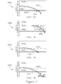
- the following variations of this scheme for defining the breakthrough are defined below and illustrated in Figure 4 in which 410A-C represent the upper boundary, 430A-C represent the lower boundary, 420A-C represent the average, and 450A-C represent the trend line as follows:
- the change in flow direction was triggered after a departure of the trend line from the dynamic window and confirmation by three subsequent contiguous ultrasonic data points that also were outside of the window boundary ("multiple departure” switch) (400A).
- the change in flow direction was triggered immediately once the trend line was out of the dynamic window boundary ("first departure” switch) (400C).
- a dynamic window that used only the initial portion of the cycle and a trend line based upon ultrasonic points in the final portion cycle (“modified first departure” switch): here only the first 30 amplitude points were used to constitute the window boundaries that remained unchanged over the duration of the test, while the trend line was formed using only the 30 last amplitude points of the current cycle (400B). All of these are particular embodiments of algorithm of the claimed invention without exhausting its generality as presented in the general description above.
- FIG. 5 A flowchart illustrating the steps in acquiring and processing the time-domain ultrasonic wave signals and executing the algorithm is shown in Figure 5 .
- the method starts off by using Lab VIEW software 510; data are being acquired and converted into a text file 520. Columns are transposed 530 and maximum and minimum are determined 540 from which amplitude is calculated 550 and then mean and standard deviation are also calculated 560.
- a graph is generated with a dynamic window over time 570 on which a trendline being a 2 nd order polynomial fitting is added 580. Then, upon breakthrough detection 590 a signal is given for intervention or the process is stopped 595.
- thermocouple or similar device may be used to continuously monitor temperature and apply an appropriate input to the program. It should be noted that the ambient temperature effects should not be confused with temperature effects due to the change in the temperature of the fluid in the system - this must also be monitored and independent corrections applied if necessary.
- A is the total amplitude difference of the wave form
- t refers to the time at which the signal was recorded
- T(t- ⁇ ) is the temperature at a time t- ⁇ before the signal A(t) was recorded at time t.
- breakthrough was related to membrane scaling.
- the "breakthrough” provides a "switch” signal. This is a signal to take preventative steps to protect the membrane from significant scaling.
- the signal is used to reverse the flow direction in the module.
- the scaling incubation time is defined as the time interval between the cycle start and the "switch" signal. This approach assumes only that the incubation time for scaling is long enough to establish a representative "window” since an incubation time based on too few data samples would potentially be unreliable.
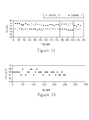
- Plots showing the cumulative standard deviation (%) for various experiments as a function of time (min) are shown in Figure 8.
- Figure 8 presents data for sensor C in the first forward-flow cycle (800A) and sensor A in the first reverse-flow cycle (800B). Standard deviation is calculated as the percentage of the mean amplitude. Results show a very small spread of average amplitude data (standard deviation is ⁇ 1%).
- the data from a range of experiments follow an overall trend in which the standard deviation for the sensors in each flow cycle approaches an asymptotic value after an initial decrease.
- the findings suggest that a minimum number of data points (or a minimum time) is necessary to establish lower and upper boundaries and a relatively constant value for the limits of the "dynamic window".
- the minimum number of data points is ⁇ 10 which correspond to ⁇ 50 min of module operation if the sampling time is every 5 minutes.
- the incubation time is determined only from the governing ultrasonic sensor which samples the membrane where supersaturation will be highest. It should be further noted that it may prove advantageous to use signals from a sensor not at the most downstream position to best control the flow reversal. In the case of a flow-reversal setup this will be the downstream sensor which is (C) in the forward-flow direction and the (original) upstream sensor (A) in the reverse-flow direction.
- the switch signal can also be used to terminate the experiment to study early-stage scaling.
- this novel methodology is simple to employ, gives reliable results and incorporates an appropriate balance between sensitivity and "false-positive" responses.
- This novel methodology was used here for the first time to successfully control flow reversal in a series of systematic and comprehensive reverse osmosis desalination experiments.
- FIG. 9 A schematic illustration of the bench-scale RO system used for evaluating the effectiveness of the ultrasonic early warning system is presented in Figure 9 .
- This RO system utilizes two 10-L plastic tanks containing aqueous solutions: one tank contains dionized (DI) water and other contains the salt solution feed. The feed tank solution is stirred continuously with a magnetic stir bar. The feed solution temperature is controlled at 23 ⁇ 1°C using an in-line coiled stainless steel heat exchanger connected to a chiller (model 9101, Fisher Scientific), and measured with a digital thermometer (model 217GA, Omega). An in-line filter (model PL-U.1x10UL, 0.1- ⁇ m, Serfilco) is installed to eliminate particulate in the bulk flow to the membrane.
- a booster pump (model 7131-1007, Little Giant Pump Co.) is placed before the in-line filter to eliminate possible cavitation in the high pressure pump.
- the feed solution is circulated through the system via a high-flow pump (model TMFR1, Fluid-O-Tech) that can provide variable flow-rates between 5 and 15 cm-s -1 .
- the RO system can operate at pressures between 690 - 1380 KPa (100 - 200 psi).
- the flat-sheet cell was fabricated from polycarbonate, and it is closed with two 12-mm-thick aluminum plates.
- the rectangular flow channel (0.077-m wide by 0.002-m thick) has a cross-sectional area of 1.54 ⁇ 10-4 m 2 .
- a double "O-ring" arrangement provides a leakproof seal at the required pressures.
- Permeate collection is divided into five separate individual sections and corresponding collection ports in order to obtain local permeate flow-rate values at different locations along the flow axis. The length of each port is 0.091 m, so the active permeation area of each port is 7.007 ⁇ 10 -3 m 2 .
- the permeate flow-rate from each of these collection ports (labeled as 1 through 5 where 1 is upstream in the forward-flow direction) is obtained from mass measurements using a balance (model TE2101, Sartorius) with a resolution of 0.1 g.
- Permeate collection occurs sequentially from each port, and flow from the port to the collection vessel is controlled by five three-way solenoid valves (model 8320G041, ASCO), one on each permeate line.
- the solenoid valve When the solenoid valve is open, the permeate flows to the vessel placed directly on the balance. The valve is opened for a total of 5 min until the next valve opens. When the valve is closed, the permeate flows directly back to the feed tank.
- the permeate solution from the vessel drains to the feed tank through a siphon.
- the balance is connected via a RS-232 cable to a laboratory PC.
- a back-pressure regulator (model BP-3-1A11I5J111, Go Regulate) is located at the outlet of the flow cell for maintaining the pressure in a flow loop.
- a pressure sensor (model PX309-300 G-5V, Omega) is located after the first pressure gauge and before the flow cell.
- a flow sensor (model 101-8E, McMillan Co.) is located on the retentate line on the outlet of the flow cell, and both a pressure sensor and a flow sensor are connected to a 12-bit multifunction I/O analog-to-digital converter (NI-USB 6008, National Instruments).
- a custom LabVIEW program (Version 8.5., National Instruments) is used to automatically record pressure and retentate flow every 2 min, and mass measurements from the balance every 30 sec; real-time retentate flow-rates, pressure and mass measurements are recorded via a laboratory PC.
- Three 10-MHz planar ultrasonic sensors (labeled as A, B and C) in a 1.27-cm diameter element (model V111, Panametrics) are mounted on ports 1, 3 and 5 for continuous monitoring of the acoustic signals.
- An ultrasonic pulser/receiver (model 505PRX, Panametrics) in conjunction with the ultrasonic sensors and a digital storage oscilloscope (model TDS3052, Tektronix) is used to process and archive real-time acoustic spectra.
- a multi-channel scanner is used for acquiring the responses from the ultrasonic sensors; the sampling area corresponding to each sensor is about 8 mm 2 .
- a second custom LabVIEW program is used to obtain composite ultrasonic spectra from the three sensors every 5 or 10 min (depending on the experiment).
- the conductivity of the feed and permeate is monitored with a conductivity meter (model 21118537, Fisher Scientific).
- Membrane salt rejection based on conductivity data during all of the experiments was in the range 97-99%.
- SV1 and SV3 Two three-way valves (SV1 and SV3) and one two-way by-pass valve (SV2) are used to ensure that the system can be operated with forward- and reverse-flow.
- the feed solution is initially delivered from the left end to the right side of the flow cell by opening valve SV1 to the right position and valve SV3 to the down position (dashed line in Figure 1 referenced by FF).
- valve SV2 When switching to reverse flow (feed solution enters the flow cell from the right and exits from the left), valve SV2 is opened and valve SV1 is set to the up position and valve SV3 to the left position (dashed line in Figure 1 referenced by RF).
- the membrane used in the experiments is XLE-440 (Filmtec), a polyamide-based extra-low energy RO membrane.
- the membrane was received from the manufacturer in roll form.
- membrane coupons of the appropriate size 510 x 110 mm
- the container used to soak the membrane was covered with aluminum foil to prevent membrane exposure to light.
- Post-mortem characterization included both gravimetric measurements and image analysis. Gravimetric measurements are obtained by comparing the mass of a test coupon to that of a virgin membrane coupon used as a reference. Results are expressed in terms of percent mass change ( ⁇ m%).
- the membrane coupons are also examined via low-magnification light microscopy (20x) and representative images of the membrane coupons surfaces are obtained.
- Commercial image analysis software (Image J, NIH) is used to analyze the microscopic images by calculating the area coverage ( ⁇ A%) that corresponds to the membrane area directly sampled by the ultrasonic sensor.
- EDS energy dispersive spectroscopy
- a numerical model was utilized for predicting the supersaturation index (SI) and the solute mass-transfer coefficient as a function of system inputs including pressure, bulk solute concentration and inlet flow-rates.
- SI supersaturation index
- solute mass-transfer coefficient as a function of system inputs including pressure, bulk solute concentration and inlet flow-rates.
- a simple film transport model (Graetz mass-transfer correlation) was applied to a parallel plate channel in which the channel height is used as the characteristic flow-channel height for calculation of the Sherwood and Reynolds numbers.
- the flow channel was divided into five consecutive sections extending from the module entrance to exit.
- the lumped one-dimensional film model was solved using the flux equation; concentration polarization was incorporated via the osmotic pressure difference between the brine feed (at the wall) and the permeate.
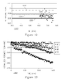
- the model was employed to determine a combination of concentration, flow velocity and pressure conditions that would enable undersaturation conditions on port 1 (SI ⁇ 1), and supersaturation (SI ⁇ 2.5-3) on port 5. As indicated from the modeling results shown in graph 1000 in Figure 10 , these SI values were predicted (line 1010) to occur with a calcium sulfate feed concentration of 0.65 gL -1 (conductivity: 890 ⁇ 99 ⁇ Scm -2 ), a pressure of 758 ⁇ 21 kPa (110 ⁇ 3 psi), and a feed flow-rate of 500 mLmin -1 , which corresponds to a cross-flow velocity of 5.4 cms -1 .
- the experiments conducted enabled the inventors to determine the sensitivity of the externally-mounted ultrasonic sensors in detecting and monitoring early-stage scaling and further enabled to firmly establish proof-of-concept for the methodology.
- DI water was initially utilized as the feed solution for at least 48 hr to complete membrane compaction.
- the permeate flow-rate decreased by 20-30% due to membrane compaction.
- the permeate flow-rate in each ports further deceased by 10-30% initially due to the change of osmotic pressure.
- the net permeate flow-rate decreased due to scaling only or increased due to (partial) cleaning of the scalant.
- the overall permeate flow-rate which is summation of the flow-rates from three selected ports (1, 3 and 5), is presented as the membrane module performance function, SUM.
- Tests 1-3 were operated in automatic switching mode with a slight modification of the dynamic window methodology.
- Test 1 the change in flow direction was triggered after a departure of the trend line from the dynamic window and confirmation by three subsequent contiguous ultrasonic data points that also were outside of the window boundary ("multiple departure" switch, MD) ( Figure 4 , graph 400A).
- Test 2 the change in flow direction was triggered immediately once the trend line was out of the dynamic window boundary ("first departure” switch, FD) ( Figure 4 , graph 400B).
- Test 3 was conducted via a dynamic window that used only the initial portion of the cycle and a trend line based upon ultrasonic points in the final portion cycle ("modified first departure" switch, MFD): here only the first 30 amplitude points were used to constitute the window boundaries that remained unchanged over the duration of the test, while the trend line was formed using only the 30 last amplitude points of the current cycle ( Figure 4 , graph 400C).
- Test 4 is a reference test with no flow reversal (no-switch test, NS) ( Figure 4 , graph 400D). The test results including the total salt phase duration, total number of FF and RF cycles, permeate flow-rate decrease in each port, net permeate flow-rate decrease for entire module (SUM), and post-mortem gravimetric and area coverage analysis are presented in Table 1.
- Test 1 immediately following introduction of the salt solution, the permeate flow-rate decreased 6, 12, and 13% at ports 1, 3, and 5, respectively, due to osmotic pressure changes.
- Test 1 was operated for 78 hr in the salt solution phase with 7 forward flow (FF) and 6 reverse flow (RF) cycles.
- the permeate flow-rate decreased by an additional 25, 17, and 17% at ports 1, 3 and 5, respectively, and the overall permeate flow-rate decreased by 24% during the salt solution phase.
- Results obtained from the ultrasonic sensors, as well as the permeate flow-rate data, were confirmed by post-mortem membrane analysis. The image analysis indicated that no scaling had occurred at port 1, whereas 9 and 16% coverage of the membrane area was observed at ports 3 and 5, respectively (Table 1 above). In addition, negligible mass change was observed on membrane coupons from the respective ports.
- Test 2 was performed using the first departure switch algorithm ( Figure 4 , graph 400B).
- the salt phase in Test 1 lasted 78.5 hr with 17 FF and 17 RF cycles.
- the permeate flow-rate initially decreased 12, 16 and 20% at ports 1, 3, and 5, respectively, due to osmotic pressure changes, and an additional 6, 5 and 10%, respectively, during the salt phase; these individual responses resulted in an overall permeate flow-rate decrease of 7%.
- the experiment was terminated at a RF cycle in which port 1 was the downstream port.
- Test 3 was 75.6 hr in duration with 19 FF and 19 RF cycles.
- the permeate flow-rate decreased 8, 4, and 5% at ports 1, 3, and 5, respectively, resulting in an overall permeate flow-rate decrease of 4% (Table 1).
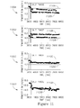
- the total permeate flow-rate as well as that for each individual port are presented in Figure 11 : port 1 is presented in 1100A; port 3 is presented in 1100C; port 5 is presented in 1100B; and overall is presented in 1110D.
- a representative dynamic window result for one of the flow cycles during this test methodology is shown in Figure 12 .
- the post-mortem gravimetric and image analysis results showed no scaling at ports 1 and 3, and only trace amounts of scaling on the downstream port (port 5).
- Test 4 was designed as a reference test for the sensor-controlled automatic FR using a dynamic window methodology. Using the same testing condition as in Tests 1-3, Test 4 was conducted without FR. The test was conducted with a ⁇ 77 hr salt phase using a single FF cycle. With the approximately same test duration as of Tests 2 and 3, the permeate flow-rate at the downstream port decreased by 55% and the overall permeate flow-rate decreased by 31%. The interpretation of the results from the ultrasonic sensors and permeate flow-rate data was confirmed by post-mortem light microscopy of the membrane surface and gravimetric analysis of the membrane coupons at the three permeation ports. Gravimetric measurements yielded a mass change of 0, 9, and 8% at ports 1, 3, and 5, respectively, and the image analysis indicated no scaling at port 1 and significant scaling at ports 3 and 5 (Table 1).
- Table 1 illustrates a summary of the results from Tests 1-4 showing the total salt phase duration, total number of FF and RF cycles, net permeate flow-rate decrease in each port and all sample ports (SUM), and post-mortem metrics: mass and area coverage.
- the apparatus is the same in example 1 except the pulser/receiver is a Olympus model 5072pr, the multiplexer used is MUX-8 (Simex Systems Be-Insp), the reflected waveforms are stored by a Tektronix TDS3012C digital oscilloscope from which they are fed to the computer.
- the A/D interface for weight, temperature, pressures and reflected waveforms is a National Instruments NI-9219 card connected to a PC.
- the process and waveform input data is analyzed by software written on the Lab VIEW platform (version 8.5) which generates the average amplitude, trend line and standard deviation window as described in the patent and in figure 4 .
- the Lab VIEW written software then sends signals via the USB 6008 D/A card to the valves to effect when the trend line intersects the operation window which is held at +/- 1 to 1.2 times the standard deviation of the average amplitude. Intersections in the first 15 minutes of each cycle are ignored since they reflect the noisiness of the initial data.
- the scaling system was a solution of 1 g/L of calcium sulfate dihydrate with a flow rate of 90 L/min and an average applied pressure of 9.5 bar.
- the membrane permeability was 7.35 L/m 2 -h.
- the same apparatus was used as in example 2.
- the feed solution was composed of 7 mM CaCl 2 and 7 mM NaHCO 3 .
- the feed pH was adjusted by bubbling CO 2 into the feed tank and was maintained by a pH controller that determined the frequency of opening and closing a solenoid leading from the CO 2 gas cylinder to an injection pipe in the feedline.
- the feed pH was maintained at 6.8. Given the equilibrium constants and calculating the concentration polarization as described in example 1, but allowing for the lower rejection of carbonic acid (73%) as opposed to calcium chloride (100%) and sodium bicarbonate ( ⁇ 98%) based on the hydrodynamic conditions, it was possible to calculate the calcite supersaturation at the membrane wall as a function of downstream distance from the port entrance.
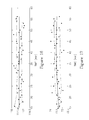
- Figures 19, 20, and 21 show the fluxes for ports 1,2,3, and 5 respectively.
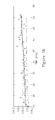
- Figure 20 shows the trend line of the ultrasonic sensor at middle of port 3
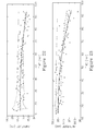
- Figures 22 and 23 show the trend line from the ultrasound sensor at the upstream end of port 5, which is the most downstream port.
- the flux in port 5 begins to decrease at about 63 min whereas the flux in port 3 begins to decrease at about 75 min.
- the flux in ports 1 and 2 are stable.
- the corresponding ultrasonic response from port 5 shows the ultrasonic signal crossing the window first (about 60 min), followed by sensor from port 3 showing decline at a somewhat later time (about 75 min).
Landscapes
- Physics & Mathematics (AREA)
- Biochemistry (AREA)
- Health & Medical Sciences (AREA)
- Life Sciences & Earth Sciences (AREA)
- Chemical & Material Sciences (AREA)
- Analytical Chemistry (AREA)
- Acoustics & Sound (AREA)
- General Health & Medical Sciences (AREA)
- General Physics & Mathematics (AREA)
- Immunology (AREA)
- Pathology (AREA)
- Investigating Or Analyzing Materials By The Use Of Ultrasonic Waves (AREA)
- Separation Using Semi-Permeable Membranes (AREA)
Claims (11)
- Verfahren zum Feststellen von Voraussetzungen von Ablagerungen, welche auf inneren Oberflächen von Leitungen von wasseraufarbeitendem Gerät auftreten, wobei das Verfahren umfasst:- Übermitteln von einem oder mehreren Ultraschallsignalen durch die Wand der Leitungen (10);- Erlangen, in Echtzeit, von für spektrale Parameter indikative Datenproben aus empfangenen Ultraschallsignalen oder deren Reflexionen;- Berechnen eines gleitenden Durchschnitts von einer Streuung der Ultraschallsignale über einen festgelegten Zeitraum basierend auf den Datenproben, welche während der Zeit t=0 bis zur Zeit t erlangt werden;- Anwenden eines statistischen Operanden auf den gleitenden Durchschnitt um eine statistische Verteilungsmetrik zu erhalten;- Bestimmen eines dynamischen Fensters, welches definiert ist durch (i) eine obere Grenze, welche der gleitende Durchschnitt plus mindestens einem Bruchteil der statistischen Verteilungsmetrik ist und (ii) eine untere Grenze, welche der gleitende Durchschnitt minus mindestens einem Bruchteil der statistischen Verteilungsmetrik ist;- Erzeugen einer Trendlinie, welche eine Anpassung von den erlangten Proben ist und- Kontrollieren der Trendlinie innerhalb des dynamischen Fensters um eine Überkreuzung der Trendlinie bei der oberen oder unteren Grenze festzustellen,
wobei das Verfahren weiterhin das dynamische Aktualisieren der Werte der oberen Grenze und der unteren Grenze und der Trendlinie in Echtzeit durch das Addieren von neu erlangten Datenproben zu diesen Datenproben und damit das neue Berechnen des gleitenden Durchschnitts umfasst. - Verfahren nach Anspruch 1, wobei die oberen und unteren Grenzen während eines Anfangszeitraums eingestellt werden und dann unverändert bleiben.
- Verfahren nach Anspruch 1, wobei die statistische Verteilungsmetrik eine Varianz oder eine Standardabweichung ist.
- Verfahren nach Anspruch 1, welches weiterhin das Auslösen eines Alarms nach dem Feststellen einer Überkreuzung umfasst.
- Verfahren nach Anspruch 1, welches weiterhin das Anwenden eines Eingriffs in das wasseraufarbeitende Gerät umfasst, so dass Ablagerungen vermieden werden.
- Verfahren nach Anspruch 5, wobei der Eingriff mindestens eines hiervon umfasst: Flussumkehr, Spülen mit untersättigtem Wasser, osmotisches Spülen und eine Verwendung einer chemischen Reinigungslösung.
- System (100) zum Feststellen von Voraussetzungen von Ablagerungen, welche auf inneren Oberflächen von Leitungen (10) von wasseraufarbeitendem Gerät auftreten, wobei das System umfasst:- mindestens ein Ultraschall-Sende-/Empfangsgerät (20A-20C), welches ausgelegt ist zum: (i) Übermitteln von einem oder mehreren Ultraschallsignalen durch die Wand der Leitungen (10), und (ii) Empfangen der Ultraschallsignale und deren Reflexionen;- einen Probennehmer, der ausgelegt ist, Proben zu entnehmen und in Echtzeit für spektrale Parameter indikative Datenproben aus empfangenen Ultraschallsignalen oder deren Reflexionen zu erlangen; und wobei das System dadurch charakterisiert ist, dass eine Verarbeitungseinheit (60) ausgelegt ist, um: (vi) einen gleitenden Durchschnitt von einer Streuung der Ultraschallsignale über einen festgelegten Zeitraum basierend auf den Datenproben, welche während der Zeit t=0 bis zur Zeit t erlangt werden, zu berechnen; (vii) einen statistischen Operanden auf den gleitenden Durchschnitt anzuwenden, um eine statistische Verteilungsmetrik zu erhalten; (viii) ein dynamisches Fenster zu bestimmen, welches definiert ist durch: (i) eine obere Grenze, welche der gleitende Durchschnitt plus mindestens einem Bruchteil der statistischen Verteilungsmetrik ist, und (ii) eine untere Grenze, welche der gleitende Durchschnitt minus mindestens einem Bruchteil der statistischen Verteilungsmetrik ist; (ix) eine Trendlinie, welche eine Anpassung der erlangten Proben ist, zu erzeugen; und (x) die Trendlinie innerhalb des dynamischen Fensters zu kontrollieren, um eine Überkreuzung der Trendlinie bei der oberen oder unteren Grenze festzustellen;
wobei die Werte der oberen Grenze und der unteren Grenze und der Trendlinie in Echtzeit durch das Addieren von neu erlangten Datenproben zu diesen Datenproben dynamisch aktualisiert werden, um damit den gleitenden Durchschnitt neu zu berechnen. - System nach Anspruch 7, welches weiterhin ein Kontrollmodul (110) umfasst, welches zum Auslösen eines Alarms nach dem Feststellen einer Überkreuzung ausgelegt ist.
- System nach Anspruch 7, welches weiterhin ein Kontrollmodul (110) umfasst, welches zum Anwenden eines Eingriffs in das wasseraufarbeitende Gerät ausgelegt ist, so dass Ablagerungen vermieden werden.
- System nach Anspruch 7, wobei das wasseraufarbeitende Gerät mindestens eines hiervon umfasst: Umkehrosmose, Nanofiltration, Ultrafiltrationsmembranen, Wärmetauscher und Wassertransportleitungen.
- System nach Anspruch 10, wobei der Eingriff mindestens eines hiervon umfasst: Flussumkehr, Spülen mit untersättigtem Wasser, osmotisches Spülen und eine Verwendung einer chemischen Reinigungslösung.
Applications Claiming Priority (2)
| Application Number | Priority Date | Filing Date | Title |
|---|---|---|---|
| US36330510P | 2010-07-12 | 2010-07-12 | |
| PCT/IB2011/053115 WO2012007909A2 (en) | 2010-07-12 | 2011-07-12 | Analyzing ultrasonic signals using a dynamic window for an early detection of scaling in water processing equipment |
Publications (2)
| Publication Number | Publication Date |
|---|---|
| EP2593783A2 EP2593783A2 (de) | 2013-05-22 |
| EP2593783B1 true EP2593783B1 (de) | 2015-09-09 |
Family
ID=44588126
Family Applications (1)
| Application Number | Title | Priority Date | Filing Date |
|---|---|---|---|
| EP11754921.2A Not-in-force EP2593783B1 (de) | 2010-07-12 | 2011-07-12 | Ultraschallsignal analyse mit hilfe eines dynamischen datenverarbeitungsfensters zur früherkennung von verkalkung in wasserbehandlunggeräten |
Country Status (6)
| Country | Link |
|---|---|
| US (1) | US9164062B2 (de) |
| EP (1) | EP2593783B1 (de) |
| ES (1) | ES2561435T3 (de) |
| IL (1) | IL223974A (de) |
| SG (1) | SG187048A1 (de) |
| WO (1) | WO2012007909A2 (de) |
Families Citing this family (8)
| Publication number | Priority date | Publication date | Assignee | Title |
|---|---|---|---|---|
| AU2012357003B2 (en) * | 2011-12-22 | 2015-02-05 | Solenis Technologies Cayman, L.P. | Method and device for detecting and analyzing deposits |
| UA117816C2 (uk) | 2012-11-06 | 2018-10-10 | Байєр Кропсайєнс Акцієнгезелльшафт | Гербіцидна комбінація для толерантних соєвих культур |
| JP6338777B2 (ja) * | 2015-07-01 | 2018-06-06 | 三菱電機株式会社 | ろ過膜蓄積物判定装置及び方法 |
| CN105974353A (zh) * | 2016-06-29 | 2016-09-28 | 南京国电南自电网自动化有限公司 | 一种基于虚拟仪器的互感器幅值与相位检测方法 |
| CN106746121A (zh) * | 2016-12-27 | 2017-05-31 | 山东奥美环境股份有限公司 | 一种脱硫废水回用及盐资源化的处理方法 |
| CN113177378B (zh) * | 2021-05-28 | 2022-05-13 | 中煤科工集团杭州研究院有限公司 | 一种用于预测矿井水在反渗透膜组件内部结垢的分析方法 |
| CN115950789B (zh) * | 2022-08-25 | 2023-08-15 | 广东工业大学 | 一种基于结晶动力学的阻垢剂性能评价方法及装置 |
| WO2024238283A1 (en) * | 2023-05-12 | 2024-11-21 | Ddp Specialty Electronic Materials Us, Llc | System for determining filter status |
Family Cites Families (7)
| Publication number | Priority date | Publication date | Assignee | Title |
|---|---|---|---|---|
| WO2000004987A1 (en) | 1998-07-21 | 2000-02-03 | University Technology Corporation | Method and apparatus for determining the state of fouling/cleaning of membrane modules |
| US20040016699A1 (en) * | 2002-07-29 | 2004-01-29 | Michael Bayevsky | Systems and methods for ultrasonic cleaning of cross-flow membrane filters |
| WO2006116533A2 (en) * | 2005-04-27 | 2006-11-02 | Hw Process Technologies, Inc. | Treating produced waters |
| EP1903335B1 (de) | 2005-06-20 | 2017-03-08 | Airbus Operations S.L. | Prozess zum ultraschallnachweis und zur vorbeugenden kontrolle von defekten in aus verbundmaterialien hergestellten teilen |
| US20090266762A1 (en) * | 2006-09-25 | 2009-10-29 | Toray Industries, Inc | Method for operating reverse osmosis membrane filtration plant, and reverse osmosis membrane filtration plant |
| WO2011097403A1 (en) * | 2010-02-04 | 2011-08-11 | Dxv Water Technologies, Llc | Water treatment systems and methods |
| US20120145633A1 (en) * | 2010-12-09 | 2012-06-14 | General Electric Company | Ultra-sound enhanced centrifugal separation of oil from oily solids in water and wastewater |
-
2011
- 2011-07-12 ES ES11754921.2T patent/ES2561435T3/es active Active
- 2011-07-12 WO PCT/IB2011/053115 patent/WO2012007909A2/en not_active Ceased
- 2011-07-12 SG SG2013002480A patent/SG187048A1/en unknown
- 2011-07-12 EP EP11754921.2A patent/EP2593783B1/de not_active Not-in-force
- 2011-07-12 US US13/809,780 patent/US9164062B2/en not_active Expired - Fee Related
-
2012
- 2012-12-27 IL IL223974A patent/IL223974A/en active IP Right Grant
Non-Patent Citations (1)
| Title |
|---|
| LALOT ET AL: "On-line detection of fouling in a water circulating temperature controller (WCTC) used in injection moulding", APPLIED THERMAL ENGINEERING, PERGAMON, OXFORD, GB, vol. 26, no. 11-12, 1 August 2006 (2006-08-01), pages 1087 - 1094, XP024987740, ISSN: 1359-4311, [retrieved on 20060801], DOI: 10.1016/J.APPLTHERMALENG.2005.11.010 * |
Also Published As
| Publication number | Publication date |
|---|---|
| WO2012007909A3 (en) | 2012-03-22 |
| IL223974A (en) | 2017-07-31 |
| SG187048A1 (en) | 2013-02-28 |
| US9164062B2 (en) | 2015-10-20 |
| WO2012007909A2 (en) | 2012-01-19 |
| US20130238133A1 (en) | 2013-09-12 |
| EP2593783A2 (de) | 2013-05-22 |
| ES2561435T3 (es) | 2016-02-26 |
Similar Documents
| Publication | Publication Date | Title |
|---|---|---|
| EP2593783B1 (de) | Ultraschallsignal analyse mit hilfe eines dynamischen datenverarbeitungsfensters zur früherkennung von verkalkung in wasserbehandlunggeräten | |
| US7910004B2 (en) | Method and system for monitoring reverse osmosis membranes | |
| Mairal et al. | Real-time measurement of inorganic fouling of RO desalination membranes using ultrasonic time-domain reflectometry | |
| Mairal et al. | Investigation of membrane fouling and cleaning using ultrasonic time-domain reflectometry | |
| Ho et al. | Monitoring fouling behavior of reverse osmosis membranes using electrical impedance spectroscopy: A field trial study | |
| JP7344201B2 (ja) | 冷却水監視制御システム | |
| KR100429744B1 (ko) | 여과 감시 및 제어 시스템 | |
| Lu et al. | Ultrasonic sensor control of flow reversal in RO desalination—Part 1: Mitigation of calcium sulfate scaling | |
| Cobry et al. | Comprehensive experimental studies of early-stage membrane scaling during nanofiltration | |
| Sanderson et al. | Ultrasonic time-domain reflectometry as a non-destructive instrumental visualization technique to monitor inorganic fouling and cleaning on reverse osmosis membranes | |
| Thompson et al. | Rapid field assessment of RO desalination of brackish agricultural drainage water | |
| Supekar et al. | Real-time detection of early-stage calcium sulfate and calcium carbonate scaling using Raman spectroscopy | |
| Mizrahi et al. | Ultrasonic sensor control of flow reversal in RO desalination. Part 2: mitigation of calcium carbonate scaling | |
| Olufade et al. | Characterization of the evolution of crystallization fouling in membranes | |
| US20170021308A1 (en) | Control of an ro installation for flushing solutions | |
| An et al. | Non-invasive measurement of membrane scaling and cleaning in spiral-wound reverse osmosis modules by ultrasonic time-domain reflectometry with sound intensity calculation | |
| KR101612231B1 (ko) | 역삼투막 베셀의 세정 진단 장치 및 방법 | |
| Johnson | Predicting log removal performance of membrane systems using in-situ integrity testing | |
| Zhang et al. | Study of membrane fouling and cleaning in spiral wound modules using ultrasonic time-domain reflectometry | |
| Kujundzic et al. | ultrasonic characterization of membranes | |
| Olufade et al. | Application of indirect non-invasive methods to detect the onset of crystallization fouling in a liquid-to-air membrane energy exchanger | |
| Kujundzic et al. | Use of ultrasonic sensors for characterization of membrane fouling and cleaning | |
| JP4728684B2 (ja) | 膜ろ過装置の膜破損診断方法および装置 | |
| US20180036686A1 (en) | Water quality monitoring device, water treatment device, water treatment system, water quality monitoring method, and program | |
| CN222196533U (zh) | 一种在线清洗反渗透系统和净水设备 |
Legal Events
| Date | Code | Title | Description |
|---|---|---|---|
| PUAI | Public reference made under article 153(3) epc to a published international application that has entered the european phase |
Free format text: ORIGINAL CODE: 0009012 |
|
| 17P | Request for examination filed |
Effective date: 20130208 |
|
| AK | Designated contracting states |
Kind code of ref document: A2 Designated state(s): AL AT BE BG CH CY CZ DE DK EE ES FI FR GB GR HR HU IE IS IT LI LT LU LV MC MK MT NL NO PL PT RO RS SE SI SK SM TR |
|
| DAX | Request for extension of the european patent (deleted) | ||
| 17Q | First examination report despatched |
Effective date: 20131107 |
|
| GRAP | Despatch of communication of intention to grant a patent |
Free format text: ORIGINAL CODE: EPIDOSNIGR1 |
|
| INTG | Intention to grant announced |
Effective date: 20150331 |
|
| GRAS | Grant fee paid |
Free format text: ORIGINAL CODE: EPIDOSNIGR3 |
|
| GRAA | (expected) grant |
Free format text: ORIGINAL CODE: 0009210 |
|
| AK | Designated contracting states |
Kind code of ref document: B1 Designated state(s): AL AT BE BG CH CY CZ DE DK EE ES FI FR GB GR HR HU IE IS IT LI LT LU LV MC MK MT NL NO PL PT RO RS SE SI SK SM TR |
|
| REG | Reference to a national code |
Ref country code: GB Ref legal event code: FG4D |
|
| REG | Reference to a national code |
Ref country code: AT Ref legal event code: REF Ref document number: 748540 Country of ref document: AT Kind code of ref document: T Effective date: 20150915 Ref country code: CH Ref legal event code: EP |
|
| REG | Reference to a national code |
Ref country code: IE Ref legal event code: FG4D |
|
| REG | Reference to a national code |
Ref country code: DE Ref legal event code: R096 Ref document number: 602011019633 Country of ref document: DE |
|
| PG25 | Lapsed in a contracting state [announced via postgrant information from national office to epo] |
Ref country code: GR Free format text: LAPSE BECAUSE OF FAILURE TO SUBMIT A TRANSLATION OF THE DESCRIPTION OR TO PAY THE FEE WITHIN THE PRESCRIBED TIME-LIMIT Effective date: 20151210 Ref country code: FI Free format text: LAPSE BECAUSE OF FAILURE TO SUBMIT A TRANSLATION OF THE DESCRIPTION OR TO PAY THE FEE WITHIN THE PRESCRIBED TIME-LIMIT Effective date: 20150909 Ref country code: LV Free format text: LAPSE BECAUSE OF FAILURE TO SUBMIT A TRANSLATION OF THE DESCRIPTION OR TO PAY THE FEE WITHIN THE PRESCRIBED TIME-LIMIT Effective date: 20150909 Ref country code: LT Free format text: LAPSE BECAUSE OF FAILURE TO SUBMIT A TRANSLATION OF THE DESCRIPTION OR TO PAY THE FEE WITHIN THE PRESCRIBED TIME-LIMIT Effective date: 20150909 Ref country code: NO Free format text: LAPSE BECAUSE OF FAILURE TO SUBMIT A TRANSLATION OF THE DESCRIPTION OR TO PAY THE FEE WITHIN THE PRESCRIBED TIME-LIMIT Effective date: 20151209 |
|
| REG | Reference to a national code |
Ref country code: LT Ref legal event code: MG4D Ref country code: NL Ref legal event code: FP |
|
| REG | Reference to a national code |
Ref country code: AT Ref legal event code: MK05 Ref document number: 748540 Country of ref document: AT Kind code of ref document: T Effective date: 20150909 |
|
| REG | Reference to a national code |
Ref country code: ES Ref legal event code: FG2A Ref document number: 2561435 Country of ref document: ES Kind code of ref document: T3 Effective date: 20160226 |
|
| PG25 | Lapsed in a contracting state [announced via postgrant information from national office to epo] |
Ref country code: SE Free format text: LAPSE BECAUSE OF FAILURE TO SUBMIT A TRANSLATION OF THE DESCRIPTION OR TO PAY THE FEE WITHIN THE PRESCRIBED TIME-LIMIT Effective date: 20150909 Ref country code: HR Free format text: LAPSE BECAUSE OF FAILURE TO SUBMIT A TRANSLATION OF THE DESCRIPTION OR TO PAY THE FEE WITHIN THE PRESCRIBED TIME-LIMIT Effective date: 20150909 Ref country code: RS Free format text: LAPSE BECAUSE OF FAILURE TO SUBMIT A TRANSLATION OF THE DESCRIPTION OR TO PAY THE FEE WITHIN THE PRESCRIBED TIME-LIMIT Effective date: 20150909 |
|
| PG25 | Lapsed in a contracting state [announced via postgrant information from national office to epo] |
Ref country code: CZ Free format text: LAPSE BECAUSE OF FAILURE TO SUBMIT A TRANSLATION OF THE DESCRIPTION OR TO PAY THE FEE WITHIN THE PRESCRIBED TIME-LIMIT Effective date: 20150909 Ref country code: EE Free format text: LAPSE BECAUSE OF FAILURE TO SUBMIT A TRANSLATION OF THE DESCRIPTION OR TO PAY THE FEE WITHIN THE PRESCRIBED TIME-LIMIT Effective date: 20150909 Ref country code: SK Free format text: LAPSE BECAUSE OF FAILURE TO SUBMIT A TRANSLATION OF THE DESCRIPTION OR TO PAY THE FEE WITHIN THE PRESCRIBED TIME-LIMIT Effective date: 20150909 Ref country code: IS Free format text: LAPSE BECAUSE OF FAILURE TO SUBMIT A TRANSLATION OF THE DESCRIPTION OR TO PAY THE FEE WITHIN THE PRESCRIBED TIME-LIMIT Effective date: 20160109 Ref country code: IT Free format text: LAPSE BECAUSE OF FAILURE TO SUBMIT A TRANSLATION OF THE DESCRIPTION OR TO PAY THE FEE WITHIN THE PRESCRIBED TIME-LIMIT Effective date: 20150909 |
|
| PG25 | Lapsed in a contracting state [announced via postgrant information from national office to epo] |
Ref country code: PL Free format text: LAPSE BECAUSE OF FAILURE TO SUBMIT A TRANSLATION OF THE DESCRIPTION OR TO PAY THE FEE WITHIN THE PRESCRIBED TIME-LIMIT Effective date: 20150909 Ref country code: PT Free format text: LAPSE BECAUSE OF FAILURE TO SUBMIT A TRANSLATION OF THE DESCRIPTION OR TO PAY THE FEE WITHIN THE PRESCRIBED TIME-LIMIT Effective date: 20160111 Ref country code: AT Free format text: LAPSE BECAUSE OF FAILURE TO SUBMIT A TRANSLATION OF THE DESCRIPTION OR TO PAY THE FEE WITHIN THE PRESCRIBED TIME-LIMIT Effective date: 20150909 Ref country code: RO Free format text: LAPSE BECAUSE OF FAILURE TO SUBMIT A TRANSLATION OF THE DESCRIPTION OR TO PAY THE FEE WITHIN THE PRESCRIBED TIME-LIMIT Effective date: 20150909 |
|
| REG | Reference to a national code |
Ref country code: DE Ref legal event code: R097 Ref document number: 602011019633 Country of ref document: DE |
|
| PLBE | No opposition filed within time limit |
Free format text: ORIGINAL CODE: 0009261 |
|
| STAA | Information on the status of an ep patent application or granted ep patent |
Free format text: STATUS: NO OPPOSITION FILED WITHIN TIME LIMIT |
|
| 26N | No opposition filed |
Effective date: 20160610 |
|
| PG25 | Lapsed in a contracting state [announced via postgrant information from national office to epo] |
Ref country code: DK Free format text: LAPSE BECAUSE OF FAILURE TO SUBMIT A TRANSLATION OF THE DESCRIPTION OR TO PAY THE FEE WITHIN THE PRESCRIBED TIME-LIMIT Effective date: 20150909 Ref country code: SI Free format text: LAPSE BECAUSE OF FAILURE TO SUBMIT A TRANSLATION OF THE DESCRIPTION OR TO PAY THE FEE WITHIN THE PRESCRIBED TIME-LIMIT Effective date: 20150909 |
|
| PG25 | Lapsed in a contracting state [announced via postgrant information from national office to epo] |
Ref country code: BE Free format text: LAPSE BECAUSE OF FAILURE TO SUBMIT A TRANSLATION OF THE DESCRIPTION OR TO PAY THE FEE WITHIN THE PRESCRIBED TIME-LIMIT Effective date: 20150909 |
|
| REG | Reference to a national code |
Ref country code: FR Ref legal event code: PLFP Year of fee payment: 6 |
|
| REG | Reference to a national code |
Ref country code: DE Ref legal event code: R119 Ref document number: 602011019633 Country of ref document: DE |
|
| REG | Reference to a national code |
Ref country code: CH Ref legal event code: PL |
|
| GBPC | Gb: european patent ceased through non-payment of renewal fee |
Effective date: 20160712 |
|
| PG25 | Lapsed in a contracting state [announced via postgrant information from national office to epo] |
Ref country code: MC Free format text: LAPSE BECAUSE OF FAILURE TO SUBMIT A TRANSLATION OF THE DESCRIPTION OR TO PAY THE FEE WITHIN THE PRESCRIBED TIME-LIMIT Effective date: 20150909 |
|
| PG25 | Lapsed in a contracting state [announced via postgrant information from national office to epo] |
Ref country code: LI Free format text: LAPSE BECAUSE OF NON-PAYMENT OF DUE FEES Effective date: 20160731 Ref country code: CH Free format text: LAPSE BECAUSE OF NON-PAYMENT OF DUE FEES Effective date: 20160731 Ref country code: DE Free format text: LAPSE BECAUSE OF NON-PAYMENT OF DUE FEES Effective date: 20170201 |
|
| REG | Reference to a national code |
Ref country code: IE Ref legal event code: MM4A |
|
| PG25 | Lapsed in a contracting state [announced via postgrant information from national office to epo] |
Ref country code: GB Free format text: LAPSE BECAUSE OF NON-PAYMENT OF DUE FEES Effective date: 20160712 |
|
| REG | Reference to a national code |
Ref country code: FR Ref legal event code: PLFP Year of fee payment: 7 |
|
| PG25 | Lapsed in a contracting state [announced via postgrant information from national office to epo] |
Ref country code: IE Free format text: LAPSE BECAUSE OF NON-PAYMENT OF DUE FEES Effective date: 20160712 |
|
| PG25 | Lapsed in a contracting state [announced via postgrant information from national office to epo] |
Ref country code: LU Free format text: LAPSE BECAUSE OF NON-PAYMENT OF DUE FEES Effective date: 20160712 |
|
| PG25 | Lapsed in a contracting state [announced via postgrant information from national office to epo] |
Ref country code: HU Free format text: LAPSE BECAUSE OF FAILURE TO SUBMIT A TRANSLATION OF THE DESCRIPTION OR TO PAY THE FEE WITHIN THE PRESCRIBED TIME-LIMIT; INVALID AB INITIO Effective date: 20110712 Ref country code: CY Free format text: LAPSE BECAUSE OF FAILURE TO SUBMIT A TRANSLATION OF THE DESCRIPTION OR TO PAY THE FEE WITHIN THE PRESCRIBED TIME-LIMIT Effective date: 20150909 Ref country code: SM Free format text: LAPSE BECAUSE OF FAILURE TO SUBMIT A TRANSLATION OF THE DESCRIPTION OR TO PAY THE FEE WITHIN THE PRESCRIBED TIME-LIMIT Effective date: 20150909 |
|
| PG25 | Lapsed in a contracting state [announced via postgrant information from national office to epo] |
Ref country code: TR Free format text: LAPSE BECAUSE OF FAILURE TO SUBMIT A TRANSLATION OF THE DESCRIPTION OR TO PAY THE FEE WITHIN THE PRESCRIBED TIME-LIMIT Effective date: 20150909 Ref country code: MK Free format text: LAPSE BECAUSE OF FAILURE TO SUBMIT A TRANSLATION OF THE DESCRIPTION OR TO PAY THE FEE WITHIN THE PRESCRIBED TIME-LIMIT Effective date: 20150909 Ref country code: MT Free format text: LAPSE BECAUSE OF NON-PAYMENT OF DUE FEES Effective date: 20160731 |
|
| REG | Reference to a national code |
Ref country code: FR Ref legal event code: PLFP Year of fee payment: 8 |
|
| PG25 | Lapsed in a contracting state [announced via postgrant information from national office to epo] |
Ref country code: BG Free format text: LAPSE BECAUSE OF FAILURE TO SUBMIT A TRANSLATION OF THE DESCRIPTION OR TO PAY THE FEE WITHIN THE PRESCRIBED TIME-LIMIT Effective date: 20150909 |
|
| PG25 | Lapsed in a contracting state [announced via postgrant information from national office to epo] |
Ref country code: AL Free format text: LAPSE BECAUSE OF FAILURE TO SUBMIT A TRANSLATION OF THE DESCRIPTION OR TO PAY THE FEE WITHIN THE PRESCRIBED TIME-LIMIT Effective date: 20150909 |
|
| PGFP | Annual fee paid to national office [announced via postgrant information from national office to epo] |
Ref country code: NL Payment date: 20220113 Year of fee payment: 11 Ref country code: ES Payment date: 20220121 Year of fee payment: 11 |
|
| PGFP | Annual fee paid to national office [announced via postgrant information from national office to epo] |
Ref country code: FR Payment date: 20220725 Year of fee payment: 12 |
|
| REG | Reference to a national code |
Ref country code: NL Ref legal event code: MM Effective date: 20220801 |
|
| PG25 | Lapsed in a contracting state [announced via postgrant information from national office to epo] |
Ref country code: NL Free format text: LAPSE BECAUSE OF NON-PAYMENT OF DUE FEES Effective date: 20220801 |
|
| REG | Reference to a national code |
Ref country code: ES Ref legal event code: FD2A Effective date: 20230829 |
|
| PG25 | Lapsed in a contracting state [announced via postgrant information from national office to epo] |
Ref country code: ES Free format text: LAPSE BECAUSE OF NON-PAYMENT OF DUE FEES Effective date: 20220713 |
|
| PG25 | Lapsed in a contracting state [announced via postgrant information from national office to epo] |
Ref country code: FR Free format text: LAPSE BECAUSE OF NON-PAYMENT OF DUE FEES Effective date: 20230731 |