EP2593778B1 - Use of a sensor for detecting liquid spilling - Google Patents
Use of a sensor for detecting liquid spilling Download PDFInfo
- Publication number
- EP2593778B1 EP2593778B1 EP11760391.0A EP11760391A EP2593778B1 EP 2593778 B1 EP2593778 B1 EP 2593778B1 EP 11760391 A EP11760391 A EP 11760391A EP 2593778 B1 EP2593778 B1 EP 2593778B1
- Authority
- EP
- European Patent Office
- Prior art keywords
- composite
- floor
- monitor
- sensor
- particles
- Prior art date
- Legal status (The legal status is an assumption and is not a legal conclusion. Google has not performed a legal analysis and makes no representation as to the accuracy of the status listed.)
- Active
Links
Images



Classifications
-
- G—PHYSICS
- G01—MEASURING; TESTING
- G01N—INVESTIGATING OR ANALYSING MATERIALS BY DETERMINING THEIR CHEMICAL OR PHYSICAL PROPERTIES
- G01N27/00—Investigating or analysing materials by the use of electric, electrochemical, or magnetic means
- G01N27/02—Investigating or analysing materials by the use of electric, electrochemical, or magnetic means by investigating impedance
- G01N27/04—Investigating or analysing materials by the use of electric, electrochemical, or magnetic means by investigating impedance by investigating resistance
- G01N27/12—Investigating or analysing materials by the use of electric, electrochemical, or magnetic means by investigating impedance by investigating resistance of a solid body in dependence upon absorption of a fluid; of a solid body in dependence upon reaction with a fluid, for detecting components in the fluid
- G01N27/125—Composition of the body, e.g. the composition of its sensitive layer
- G01N27/126—Composition of the body, e.g. the composition of its sensitive layer comprising organic polymers
-
- G—PHYSICS
- G01—MEASURING; TESTING
- G01N—INVESTIGATING OR ANALYSING MATERIALS BY DETERMINING THEIR CHEMICAL OR PHYSICAL PROPERTIES
- G01N27/00—Investigating or analysing materials by the use of electric, electrochemical, or magnetic means
- G01N27/02—Investigating or analysing materials by the use of electric, electrochemical, or magnetic means by investigating impedance
- G01N27/04—Investigating or analysing materials by the use of electric, electrochemical, or magnetic means by investigating impedance by investigating resistance
- G01N27/12—Investigating or analysing materials by the use of electric, electrochemical, or magnetic means by investigating impedance by investigating resistance of a solid body in dependence upon absorption of a fluid; of a solid body in dependence upon reaction with a fluid, for detecting components in the fluid
-
- G—PHYSICS
- G01—MEASURING; TESTING
- G01R—MEASURING ELECTRIC VARIABLES; MEASURING MAGNETIC VARIABLES
- G01R27/00—Arrangements for measuring resistance, reactance, impedance, or electric characteristics derived therefrom
- G01R27/02—Measuring real or complex resistance, reactance, impedance, or other two-pole characteristics derived therefrom, e.g. time constant
-
- Y—GENERAL TAGGING OF NEW TECHNOLOGICAL DEVELOPMENTS; GENERAL TAGGING OF CROSS-SECTIONAL TECHNOLOGIES SPANNING OVER SEVERAL SECTIONS OF THE IPC; TECHNICAL SUBJECTS COVERED BY FORMER USPC CROSS-REFERENCE ART COLLECTIONS [XRACs] AND DIGESTS
- Y10—TECHNICAL SUBJECTS COVERED BY FORMER USPC
- Y10T—TECHNICAL SUBJECTS COVERED BY FORMER US CLASSIFICATION
- Y10T436/00—Chemistry: analytical and immunological testing
- Y10T436/21—Hydrocarbon
- Y10T436/218—Total hydrocarbon, flammability, combustibility [e.g., air-fuel mixture, etc.]
Definitions
- Present description concerns generally to a sensor or a sensor system for detecting spilling of aqueous liquids, for instance in confined spaces were such is critical such as in an airplane.
- the system of present description is an early warning system or sentinel for the prevention of corrosion by corrosive liquids. Corrosion caused by corrosive liquids can rapidly change the surface properties of components in engineering structures, and that will finally endanger the functionality of structural parts.
- monitoring technologies are in place providing continuous information on the presence of corrosive liquids, corrosion treatment and even corrosion prevention can start at a very early stage.
- Present invention provides such by early detection of corrosive liquids by extended sensors based on the collapse of percolation conductivity (COPC).
- COPC percolation conductivity
- various leakage sensors for aqueous liquids could be used to monitor the floor beam.
- the challenge is always the limited space available in the floor beam structure, the difference between baseline variations at normal operations and the signals after ingressing liquids, the price of the instrumentation, certification issues etc.
- Such monitoring system must accurately detect intrusion or ingression of aqueous liquids spills into or under the floor cover (e.g. the carpet) for instance in the floor beam area. But the monitoring system may not be disturbed for instance by normal variations of the atmospheric humidity in the confined environment above the floor cover.
- US2005/150778 describes a sensor comprising regions of an amine-containing material (e.g. a polyimine) and regions of a conductive material, wherein the sensor provides an electrical path through the regions of the amine-containing material and the conductive material.
- the sensor is constructed to provide a first response when contacted with a first chemical analyte and a second different response when contacted with a second different chemical analyte.
- US 5256574 describes a chemically actuated electronic switch comprising from 10-30 weight percent of a small particle size, high structure carbon black homogeneously dispersed in a silicone matrix.
- the switch is normally conductive but switches to a high resistance state when contacted with and swollen by liquid hydrocarbons.
- a typical example is the floor beam area in aircraft; the floor beams are covered by protective coatings, and the joints between floor panels are equipped with sophisticated sealing systems.
- a reliable sensor or sensor network for aqueous liquids which is interrogated in the time frame of days, or even more frequently, could help to the reduce repair costs of floor beams considerably and they can even lead to a reduction of the number of inspections.
- An important challenge concerning the installation of sensors in the floor beam area is the limited space available. Furthermore, the sensor has to cover an extended area.
- a sensor is presented that is based on the transition of the percolation threshold of a composite comprising a conducting compound which is embedded in a hydrophilic matrix.
- the components are mixed in an appropriate ratio, resulting in a composition so that the composite is above the percolation threshold, i.e. in the conducting state.
- the disclosure is broadly drawn to a gauge comprising a sensing material that is a composite comprising at least two components.
- a dispersed electrically-conductive material b) a lyophilic matrix for embedding the dispersed electrically-conductive material (usually, but not necessarily performed as a polymer).
- concentration, dispersion and/or orientation of the electrically-conductive particles are tailored to be as far as possible from the percolation threshold (see gap between operational range "A" and the leakage case "B" in figure 1 ) in a way that the composite itself is always in the electrically-conductive state at normal operations.
- the percolation conductivity is essentially interrupted if a relevant amount of solvent (less than 0.5 ml, harmful quantity of aqueous solvents or oily liquids or harmful organic solvents) has entered the lyophilic composite, i.e. the disappearance of conductivity is a consequence of the swelling of the lyophilic embedding matrix (thus by transition through the threshold of percolation conductivity (collapse of percolation conductivity, COPC) into the non-conductive state).
- solvent less than 0.5 ml, harmful quantity of aqueous solvents or oily liquids or harmful organic solvents
- Another aspect is the transition through a threshold of percolation conductivity (collapse of percolation conductivity (COPC)), instead of a gradual measure of the conductivity for instance as a function of water vapour pressure.
- COPC percolation conductivity
- the sensor of present invention explicitly uses that collapse of percolation conductivity (COPC), and variations of the conductivity in the conducting state according to the previous sensor just appear as baseline variations in our applications that are not used for sensing purposes.
- the conductivity changes many orders of magnitude.
- the final resistance in the non-conducting state can go beyond approximately 100 MOhm (depending on the sensor size), and it is mainly determined by the remaining conductivity of the aqueous phase forming an own percolation network.
- the sensors function as an electrical safety fuse that after exposing to a harmful event, it loses its conductivity for a sufficient long time.
- An embodiment concerns a monitor adapted to monitor a floor structure in a confined environment, whereby the monitor comprises a sensing material [1] and at least one electrode [3] for measuring resistance in the sensing material [1], whereby the sensing material [1], which is adapted to detect hidden aqueous liquids and/or corrosive liquids under a carpet or protective cover of an underlying floor structure (e.g.
- the floor beam structure comprises a composite and the composite comprises at least two components: 1) particles or powder of an electrically-conductive material dispersed in 2) a matrix that is hydrophilic or that is highly solvable to aqueous fluids and whereby the concentration, dispersion and/or orientation of the electrically-conductive particles or powder are tailored to grow resistance until a conductivity percolation threshold after entering of a liquid, for instance spilled liquids or condensation liquids, into the composite.
- the monitor is adapted to monitor a floor structure in a confined environment, whereby the monitor, comprises a sensing material [1] and an electrode or plurality of electrodes [3] for measuring resistance in the sensing material [1], which sensing material [1] is adapted to detect hidden aqueous liquids and/or corrosive liquids, under a carpet or protective cover of an underlying floor structure (e.g.
- the sensing material [1] comprises a composite which comprises at least two components: 1) particles or powder of an electrically-conductive material dispersed in 2) a matrix that is hydrophilic or that is highly solvable to aqueous fluids and whereby the concentration, dispersion and/or orientation of the electrically-conductive particles or powder are tailored above a percolation threshold or are tailored to be as far as possible from the percolation threshold (see gap between operational range "A” and the leakage case "B” in figure 1 ) in a way that the composite itself is always in the electrically-conductive state at normal aircraft operations, but has the percolation conductivity interrupted after entering of aqueous liquid into the composite.
- a monitor is adapted to monitor a floor structure in a confined environment, whereby the monitor, comprises a sensing material [1] and an electrode or a plurality of electrodes [3] for measuring resistance in the sensing material [1], whereby the sensing material [1] is adapted to detect hidden aqueous liquids and/or corrosive liquids, for instance spilled liquids or condensation liquids under a carpet or protective cover of the underlying floor structure (e.g.
- the sensing material [1] is in the form of a wired sensor and comprises a composite which comprises itself at least two components: 1) particles or powder of an electrically-conductive material dispersed in 2) an matrix that is hydrophilic or that is highly solvable to aqueous fluids with the concentration, dispersion and/or orientation of the electrically-conductive particles or powder being adapted to induce a resistance jump in said composite (the percolation threshold) if part of the wire is exposed to an aqueous liquid (for instance a water drop).
- the monitor as described above is characterized by any of the following features explained hereunder.
- the monitor is characterised in that the conductivity percolation threshold is sudden collapse of percolation conductivity.
- the monitor is characterised in that the resistance grows until a conductivity percolation threshold is reached followed by a consequent sudden collapse of percolation conductivity.
- the monitor is characterised in that said monitor does not changes its conductivity as a function of water vapour pressure in a confined environment above the carpet or protective cover of floor beams.
- the monitor is characterised in that collapse of percolation conductivity or sudden increase of the resistance is only due to the ingress of aqueous liquid when its composite is exposed to the aqueous liquid.
- the monitor is characterised in that the conductivity is essentially lost when the sensing material [1] placed under the carpet or protective cover of the floor beams takes up the liquid.
- the monitor is characterised in that it is insensitive to an alteration of the atmospheric humidity or the water vapour above the carpet or protective cover of floor beams.
- the monitor is characterised in that the monitor is insensitive to humidity variations under 70%.
- the monitor is characterised in that ingress of aqueous liquid into the floor structure causes collapse of percolation conductivity in said sensing material of said monitor.
- the monitor is characterised in that the monitor operates real-time.
- the monitor is characterised in that the sensing material forms a sensor or sensors. Or the monitor is characterised in that the sensing material forms an in situ sensor or in situ sensors.
- the monitor as embodied in the description above is in a particular embodiment characterized in that the confined environment is an area in an aircraft and the floor structure is the sealed floor beam area in the aircraft.
- the confined environment can be a passengers room, a cargo room or a cockpit room in an aircraft.
- the monitor comprises a sensing system of elongated sensors, sensor tubings, sensor cables, cord sensor or sensor fibres.
- Such sensing system in a particular embodiment comprises a multiple sensor arrangement.
- the multiple sensor arrangement can form an array for instance a regular periodic array.
- the sensing system comprises sensing fibre channels; or the sensing system a multiple fibre arrangement, the multiple fibre arrangement can form a net.
- Another aspect concerns specific features of the elongated sensor so can the elongated sensors be coated by an isolating coating or a fabric [2] that is permeable for the aqueous liquids, for instance a coating comprising nylon cord; the elongated sensors can be channelled in liquid collecting sinks in the floor or between the floor plates above the floor beams; the elongated sensors can be attached to the floor carpet or the floor protection; the elongated sensors can be integrated in the floor carpet or the floor protection; the elongated sensors can be multicore sensor cord cables each sensor cord having a different percolation threshold.
- the isolating coating of said sensor core does not resist an attack by spilled corrosive fluids.
- the monitor according to the embodied invention described above comprises sensors which are elongated sensors, sensor tubings, sensor cables, cord sensor or sensor fibres and the eventually elongated sensors are multicore sensor cord cables and eventually elongated sensors are multicore sensor cord cables each sensor cord having a different percolation threshold which sensors are incorporated in a tape, sheet or fabric for attaching to a surface for instance an the aircraft floor such to capture into the sensing materials the spilled aqueous liquids.
- a preferred embodiment of the monitor is characterized in that the conductivity of the sensing material is interrupted as consequence of the absorption of the aqueous fluid into the matrix embedding the electrically-conductive material powder or particles by transition through the threshold of percolation conductivity (collapse of percolation conductivity into the non-conductive state).
- the disclosure furthermore relates to a monitor according to any of the above described embodiments 1) whereby the conductive particles are of the group consisting metal particle (which can be the metal particle is nickel, cupper or silver or a particle coated with nickel, cupper or silver), a particle coated by said metal, a carbon black particles and particles of conductive ceramics or 2) whereby the conductive particles are a titantiumcarbonitride (TiCN) powder.
- the conductive particles are of the group consisting metal particle (which can be the metal particle is nickel, cupper or silver or a particle coated with nickel, cupper or silver), a particle coated by said metal, a carbon black particles and particles of conductive ceramics or 2) whereby the conductive particles are a titantiumcarbonitride (TiCN) powder.
- the monitor comprises a matrix which is a hydrophilic matrix.
- the matrix comprises a polymer that is hygroscopic, or the matrix comprises polyvinyl alcohol and/or the matrix swells when it is exposed to a liquid water phase.
- the resistance in the composite increases which can be displayed on a screen after processing in that the curve of resistance (Ohm) vs. time (min) shows an increase in the resistance.
- the monitor comprises elongated sensors whereby the integral length of the elongated sensors, sensor tubings, sensor cables, cord sensor or sensor fibres has 2 m or more than 0,2 m; whereby the diameter of elongated sensors, sensor tubings, sensor cables, cord sensor or sensor fibres has a diameter of 1 mm or more than 0.5 mm, whereby the diameter of elongated sensors, sensor tubings, sensor cables, cord sensor or sensor fibres has a diameter of 1 between 0.7 and 1,2 mm, whereby the sensing material covered surface is about 0,30 cm 2 , whereby volume to add when layers have approx.
- 100 micron is between 25 - 35 cm 3 and preferably 29 - 31 cm 3 , whereby the matrix is a polymer with a density between 0.5 to 1.5 g/cm 3 , preferably between 0.8 and 1.2 g/cm 3 , more preferably 0.9 and 1.1 g/cm 3 and most preferably around 1 g/cm 3 .
- the monitor comprises a controller based on a software assisted measurement system and control algorithm.
- the controller can have a computer readable medium tangibly embodying computer code executable on a processor.
- Particular aspects hereby are a processor connected to provide a control signal to an actuator configured to signal or alarm the aqueous liquid spillage, or a processor is connected to provide a control signal to an actuator configured to alert pilot or third party, or the processor is connected to provide a control signal to an actuator configured to locate the aircraft aqueous liquid spillage defect.
- the controller of the monitor operates as a safety fuse for spilling aqueous liquids whereby the noise caused by small conductance variations that occur during operations (temperature variations, aging of adhesives etc) is disregarded by the processor but whereby an essentially loss of conductivity is regarded as an aircraft aqueous liquid spillage.
- the monitor comprises further a memory for storing the information signals and at least one transmitter for transmitting information signals to a base station adapted to receive information signals.
- this base station is adapted to transmit interrogation signals.
- at least one transmitter can be formed by a transponder which is adapted to receive the interrogation signals and to transmit information signals stored in the memory in response to receiving an interrogation signal and furthermore the at least one transmitter or transponder can be adapted to receive and transmit signals in the ether or the at least the base station is adapted to receive and transmit signals via a telephone network or the transmitter or transponder is adapted for information communication via a mobile telephone network.
- the increase of the resistance due to the ingress of water is monitored by a digital multi-channel multimeter that is equipped with appropriate data logging facilities.
- Yet another preferred embodiment concerns a self monitoring floor comprising the monitor according to any one of the above described embodiments, further comprising 1) joining floor panels, 2) joints between the floor panels and eventually a sealing system between said floor panel joints, 3) a cover or protective coating and 4) a floor structure or a floor beam area.
- the invention concerns the use of the above described monitors.
- Particular uses of the monitor according to any one of the previous embodiments or of the self monitoring floor described here above are 1) as a continuous or a intermediate but automated early warning system or sentinel for the prevention of corrosion by corrosive liquids; or 2) as a continuous or a intermediate but automated early warning system or sentinel for the prevention of corrosion by corrosive liquids; or 3) for in-situ providing continuous information and/or monitoring the presence of corrosive liquids so that corrosion treatment or corrosion prevention can start at a very early stage, or 4) to monitor the floor beam for hidden aqueous liquids in an aircraft for instance under a carpet or a protective coating of the floor beam, or 5) to protect underlying floor structure.
- the monitor is particular suitable for a floor structure which comprises or is essentially composed of a corrosive material or for a floor structure which comprises or is essentially composed of aluminium alloys.
- TiCN titaniumcarbonitride
- PVA polyvinyl alcohol
- the matrix material (PVA), a polymer that is hygroscopic, i.e. it swells when it is exposed to a gaseous or liquid water phase.
- the components were mixed with an appropriate amount of water and sufficiently stirred until a homogenous substance was obtained.
- a wire was drawn on an acrylic plate (width of about 2 mm and a length of 150 mm). The material at both ends was in direct contact with respective electrodes. The thickness was slightly varying and estimated to be in the range of 500 micrometer. After a drying time of 16 hours, the resistance was measured with a digital multimeter to be in the range of 25 Ohm. This means an estimated specific resistance of about 3000 S/m. After exposing a part of the wire to a water drop, the resistance grows gradually until the range of 100 Ohm. From this point on, a resistance jump occurred until the range of 100 kOhm and that jump could finally be identified as the percolation threshold.
- the final resistance was reached at about 600 kOhm.
- the corresponding specific resistance can be estimated to be in the range of 2 S/m.
- the curve shown in the diagram ( figure 2 ) represents a kinetic process driven by the diffusion of water into the PVA matrix, i.e. when changing e.g. the mass of the sample, the initial water amount, exposed surface etc. the curve would change its kinetic parameters.
- the conductivity above the percolation threshold is not due to the percolated ceramic powder, but due to the ions dissolved in the aqueous phase that on its own has started to create a percolation network.
- a new sample was prepared with the same specifications such as described above.
- the starting substance (PVA+TiCN+H 2 O) was deposited on a cord of polyamides. That cord is sometimes implemented in aircraft floor beam sealings to enable a proper removal of the sealings between the floor beams during regular maintenance operations.
- an isolated electric wire was mounted into the core of the polyamide cord for the required electric connections.
- the composite was uniformly deposited on the polyamide cord using a specific vessel, i.e. deposition occurred when the cord was pulled through this vessel. At the edges, the composite was in contact with the flex wires of the electrical cable to establish a continuous circuit if resistance measurements are performed.
- An important feature of this invention is the stability of the non-conducting state. Once, a relevant amount of liquid has entered the floor beam area, the sensor will absorb this liquid because ingressing liquid has to pass the positions of the sensor ( figures 4 and 5 , drawings 1 and 2). The absorbed liquid interrupts the electrical contact at a certain position. Due to the relatively high sample amount, the thickness of the coating and the length of the sensor, the drying time of the sensor is extremely long, especially in the confined space of floor plate joints in aircraft. It could be shown that in a lab experiment, the extraordinary high resistance will be maintained for many days. This means that the read-out of the sensor must not necessary be done during flight operations, but it can be done by electronic devices that are not part of the operational electronics. This essentially reduces the certification efforts when implementing the sensors reducing the costs of the overall system.
Landscapes
- Chemical & Material Sciences (AREA)
- Chemical Kinetics & Catalysis (AREA)
- Electrochemistry (AREA)
- Physics & Mathematics (AREA)
- Health & Medical Sciences (AREA)
- Life Sciences & Earth Sciences (AREA)
- Analytical Chemistry (AREA)
- Biochemistry (AREA)
- General Health & Medical Sciences (AREA)
- General Physics & Mathematics (AREA)
- Immunology (AREA)
- Pathology (AREA)
- Investigating Or Analyzing Materials By The Use Of Electric Means (AREA)
Description
- Present description concerns generally to a sensor or a sensor system for detecting spilling of aqueous liquids, for instance in confined spaces were such is critical such as in an airplane. The system of present description is an early warning system or sentinel for the prevention of corrosion by corrosive liquids. Corrosion caused by corrosive liquids can rapidly change the surface properties of components in engineering structures, and that will finally endanger the functionality of structural parts. However, if monitoring technologies are in place providing continuous information on the presence of corrosive liquids, corrosion treatment and even corrosion prevention can start at a very early stage. Present invention provides such by early detection of corrosive liquids by extended sensors based on the collapse of percolation conductivity (COPC). The term collapse refers to the fact that the transition into the non-conducting state must not necessarily have the properties of a thermodynamically well-defined transition.
- Leakage of liquids into the sealed floor beam area in aircraft is normally not monitored in nowadays maintenance operations because the respective structures are hidden and difficult to access. Respective problems can be detected only at regular heavy inspections (D-checks, or heavy maintenance, usually ranging between four and six years) or when corrosion damage gets obvious, when e.g. seats lose mechanical contacts to the seat tracks when the respective structural elements are essentially corroded. A monitoring system would thus enable huge cost savings when the presence of corrosive liquids could be detected at a very early stage.
- In principle, various leakage sensors for aqueous liquids could be used to monitor the floor beam. However, the challenge is always the limited space available in the floor beam structure, the difference between baseline variations at normal operations and the signals after ingressing liquids, the price of the instrumentation, certification issues etc. Such monitoring system must accurately detect intrusion or ingression of aqueous liquids spills into or under the floor cover (e.g. the carpet) for instance in the floor beam area. But the monitoring system may not be disturbed for instance by normal variations of the atmospheric humidity in the confined environment above the floor cover.
- A publication (
US6717664 ) proposes an optical fibre system to enable the use of a boroscope for inspecting longer distances in the hidden space of the floor beam area. However, this would nevertheless require time-consuming manual inspections and probably not all spaces could be accessed. - In another patent publication (
US6063486 ), a sensor is reported that provides a gradual measure of the humidity when measuring the conductivity of a conductive composite at different water vapour pressures. Such sensor is not suitable for the object of present invention. That sensor is intended to measure the humidity over a broader range, and it focuses on repeatability, fast measuring and sensor stability. In our case, variations of the humidity in the floor beam area is usually limited at normal operations (RH=10-20%), and the ingress of aqueous liquids would immediately cause humidities close to RH=100 %, for instance above 75%, preferably above 85%, more preferably above 95%, yet more preferably above 97 %, yet more preferably above 99 % and most preferably above 99% (seefigure 1 ). To discriminate between unimportant baseline variations (change of humidity at normal operations) and the ingress of aqueous liquid, the collapse of percolation conductivity (COPC) is used (see below) that is not mentioned nor exploited in the art. There are also other sensors known that describe the use of the change of conductivity as a function of the concentration of the conducting particle. It is e.g. well-known that the very hygroscopic salt LiCl2 changes its conductivity as a function of water vapour pressure making resistance measurements of that salt to an interesting tool for measuring humidities.DE 199 63 188 discloses a moisture sensor, comprising a moisture sensitive membrane interposed between a pair of electrodes. The moisture sensitive membrane comprises electrically conductive particles dispersed in a hygroscopic polymer. -
US2005/150778 describes a sensor comprising regions of an amine-containing material (e.g. a polyimine) and regions of a conductive material, wherein the sensor provides an electrical path through the regions of the amine-containing material and the conductive material. The sensor is constructed to provide a first response when contacted with a first chemical analyte and a second different response when contacted with a second different chemical analyte. -
US 5256574 describes a chemically actuated electronic switch comprising from 10-30 weight percent of a small particle size, high structure carbon black homogeneously dispersed in a silicone matrix. The switch is normally conductive but switches to a high resistance state when contacted with and swollen by liquid hydrocarbons. - Areas that are prone to corrosion damage are normally isolated from the wet environment. A typical example is the floor beam area in aircraft; the floor beams are covered by protective coatings, and the joints between floor panels are equipped with sophisticated sealing systems.
- However, coatings and sealings can be damaged due to the intensive use of the aircraft. Aqueous liquids arising from spillage (especially in the galley and lavatory area) or from passengers boarding at rainy weather conditions can enter the space between the floor panels, and it is known that this penetration can cause heavy corrosion in the underlying floor structure that is frequently made of aluminium alloys (corrosion is accelerated by galvanic corrosion with composite floor plates). As the regular maintenance of floor beams is scheduled with relatively long periods (usually between four and six years), a starting corrosion problem can remain undiscovered for a long time.
- A reliable sensor or sensor network for aqueous liquids which is interrogated in the time frame of days, or even more frequently, could help to the reduce repair costs of floor beams considerably and they can even lead to a reduction of the number of inspections. An important challenge concerning the installation of sensors in the floor beam area is the limited space available. Furthermore, the sensor has to cover an extended area.
- In the present invention, a sensor is presented that is based on the transition of the percolation threshold of a composite comprising a conducting compound which is embedded in a hydrophilic matrix. The components are mixed in an appropriate ratio, resulting in a composition so that the composite is above the percolation threshold, i.e. in the conducting state.
- When this composite is exposed to water, the system takes up the liquid until the conductivity is essentially lost. The increase of the resistance due to the ingress of water could at a later stage be monitored by a digital multi-channel multimeter that is equipped with appropriate data logging facilities. However, this is not necessary because the sensor "remembers" the ingress of liquids so that the reading-out can be performed by instruments that are not on board. This essentially reduces the certification effort of that technique.
- The applicability of the integral system could already be shown in a relevant lab-environment using different aqueous liquids and it is also implemented in an operational airliner.
- In accordance with the purpose of the invention, as embodied and broadly described herein, the disclosure is broadly drawn to a gauge comprising a sensing material that is a composite comprising at least two components. 1) a dispersed electrically-conductive material b) a lyophilic matrix for embedding the dispersed electrically-conductive material (usually, but not necessarily performed as a polymer). The concentration, dispersion and/or orientation of the electrically-conductive particles are tailored to be as far as possible from the percolation threshold (see gap between operational range "A" and the leakage case "B" in
figure 1 ) in a way that the composite itself is always in the electrically-conductive state at normal operations. Finally, the percolation conductivity is essentially interrupted if a relevant amount of solvent (less than 0.5 ml, harmful quantity of aqueous solvents or oily liquids or harmful organic solvents) has entered the lyophilic composite, i.e. the disappearance of conductivity is a consequence of the swelling of the lyophilic embedding matrix (thus by transition through the threshold of percolation conductivity (collapse of percolation conductivity, COPC) into the non-conductive state). - Another aspect is the transition through a threshold of percolation conductivity (collapse of percolation conductivity (COPC)), instead of a gradual measure of the conductivity for instance as a function of water vapour pressure. The sensor of present invention explicitly uses that collapse of percolation conductivity (COPC), and variations of the conductivity in the conducting state according to the previous sensor just appear as baseline variations in our applications that are not used for sensing purposes. At the COPC, the conductivity changes many orders of magnitude. The final resistance in the non-conducting state can go beyond approximately 100 MOhm (depending on the sensor size), and it is mainly determined by the remaining conductivity of the aqueous phase forming an own percolation network.
- In still another aspect the sensors function as an electrical safety fuse that after exposing to a harmful event, it loses its conductivity for a sufficient long time.
- Some embodiments are set forth directly below. An embodiment concerns a monitor adapted to monitor a floor structure in a confined environment, whereby the monitor comprises a sensing material [1] and at least one electrode [3] for measuring resistance in the sensing material [1], whereby the sensing material [1], which is adapted to detect hidden aqueous liquids and/or corrosive liquids under a carpet or protective cover of an underlying floor structure (e.g. floor beam structure), comprises a composite and the composite comprises at least two components: 1) particles or powder of an electrically-conductive material dispersed in 2) a matrix that is hydrophilic or that is highly solvable to aqueous fluids and whereby the concentration, dispersion and/or orientation of the electrically-conductive particles or powder are tailored to grow resistance until a conductivity percolation threshold after entering of a liquid, for instance spilled liquids or condensation liquids, into the composite.
- In another embodiment of the monitor the monitor is adapted to monitor a floor structure in a confined environment, whereby the monitor, comprises a sensing material [1] and an electrode or plurality of electrodes [3] for measuring resistance in the sensing material [1], which sensing material [1] is adapted to detect hidden aqueous liquids and/or corrosive liquids, under a carpet or protective cover of an underlying floor structure (e.g. floor beam structure), whereby the sensing material [1] comprises a composite which comprises at least two components: 1) particles or powder of an electrically-conductive material dispersed in 2) a matrix that is hydrophilic or that is highly solvable to aqueous fluids and whereby the concentration, dispersion and/or orientation of the electrically-conductive particles or powder are tailored above a percolation threshold or are tailored to be as far as possible from the percolation threshold (see gap between operational range "A" and the leakage case "B" in
figure 1 ) in a way that the composite itself is always in the electrically-conductive state at normal aircraft operations, but has the percolation conductivity interrupted after entering of aqueous liquid into the composite.
According to one aspect a monitor is adapted to monitor a floor structure in a confined environment, whereby the monitor, comprises a sensing material [1] and an electrode or a plurality of electrodes [3] for measuring resistance in the sensing material [1], whereby the sensing material [1] is adapted to detect hidden aqueous liquids and/or corrosive liquids, for instance spilled liquids or condensation liquids under a carpet or protective cover of the underlying floor structure (e.g. floor beam structure), characterized in that the sensing material [1] is in the form of a wired sensor and comprises a composite which comprises itself at least two components: 1) particles or powder of an electrically-conductive material dispersed in 2) an matrix that is hydrophilic or that is highly solvable to aqueous fluids with the concentration, dispersion and/or orientation of the electrically-conductive particles or powder being adapted to induce a resistance jump in said composite (the percolation threshold) if part of the wire is exposed to an aqueous liquid (for instance a water drop). - According to another aspect the monitor as described above is characterized by any of the following features explained hereunder. The monitor is characterised in that the conductivity percolation threshold is sudden collapse of percolation conductivity. The monitor is characterised in that the resistance grows until a conductivity percolation threshold is reached followed by a consequent sudden collapse of percolation conductivity. The monitor is characterised in that said monitor does not changes its conductivity as a function of water vapour pressure in a confined environment above the carpet or protective cover of floor beams. The monitor is characterised in that collapse of percolation conductivity or sudden increase of the resistance is only due to the ingress of aqueous liquid when its composite is exposed to the aqueous liquid. The monitor is characterised in that the conductivity is essentially lost when the sensing material [1] placed under the carpet or protective cover of the floor beams takes up the liquid. The monitor is characterised in that it is insensitive to an alteration of the atmospheric humidity or the water vapour above the carpet or protective cover of floor beams. The monitor is characterised in that the monitor is insensitive to humidity variations of RH=10-20%. The monitor is characterised in that the monitor is insensitive to humidity variations under 70%. The monitor is characterised in that ingress of aqueous liquid into the floor structure causes collapse of percolation conductivity in said sensing material of said monitor. The monitor is characterised in that the concentration, dispersion and/or orientation of the electrically-conductive particles or powder is in a way that the composite itself is normally in the electrically-conductive state but has the percolation conductivity interrupted after entering of aircraft aqueous fluid into the composite of said sensor detects ingress of aqueous liquid or humidities of at least RH=80 % under a carpet or protective cover of floor beams but is relatively insensitive to moisture or humidity variation in the atmosphere of the aircraft above the carpet or protective cover of floor beams of said aircraft. The monitor is characterised in that the monitor is characterised in that the concentration, dispersion and/or orientation of the electrically-conductive particles or powder is in a way that the composite itself is normally in the electrically-conductive state but has the percolation conductivity interrupted after entering of aircraft aqueous fluid into the composite of said sensor detects ingress of aqueous liquid or humidities close to RH=100 % under a carpet or protective cover of floor beams but is relatively insensitive to moisture or humidity variation in the atmosphere of the aircraft above the carpet or protective cover of floor beams of said aircraft. The monitor is characterised in that the monitor operates real-time. The monitor is characterised in that the sensing material forms a sensor or sensors. Or the monitor is characterised in that the sensing material forms an in situ sensor or in situ sensors.
- It is an object to realize an aircraft monitor and more particularly an aircraft floor monitor to protect said aircraft from destruction by ingress of water or watery fluid under the floor cover. Experiments showed that the above described monitors are perfectly suited for this function.
- According to another aspect the monitor as embodied in the description above is in a particular embodiment characterized in that the confined environment is an area in an aircraft and the floor structure is the sealed floor beam area in the aircraft. Such confined environment can be a passengers room, a cargo room or a cockpit room in an aircraft.
- According to other aspect the monitor according to any of the above mentioned embodiments comprises a sensing system of elongated sensors, sensor tubings, sensor cables, cord sensor or sensor fibres. Such sensing system in a particular embodiment comprises a multiple sensor arrangement. The multiple sensor arrangement can form an array for instance a regular periodic array.
- Other aspects concern different sensing system arrangements that can be features of such monitor described above. For instance the sensing system comprises sensing fibre channels; or the sensing system a multiple fibre arrangement, the multiple fibre arrangement can form a net. Another aspect concerns specific features of the elongated sensor so can the elongated sensors be coated by an isolating coating or a fabric [2] that is permeable for the aqueous liquids, for instance a coating comprising nylon cord; the elongated sensors can be channelled in liquid collecting sinks in the floor or between the floor plates above the floor beams; the elongated sensors can be attached to the floor carpet or the floor protection; the elongated sensors can be integrated in the floor carpet or the floor protection; the elongated sensors can be multicore sensor cord cables each sensor cord having a different percolation threshold. Preferably the isolating coating of said sensor core does not resist an attack by spilled corrosive fluids.
- In addition or as an alternative thereto, the monitor according to the embodied invention described above, comprises sensors which are elongated sensors, sensor tubings, sensor cables, cord sensor or sensor fibres and the eventually elongated sensors are multicore sensor cord cables and eventually elongated sensors are multicore sensor cord cables each sensor cord having a different percolation threshold which sensors are incorporated in a tape, sheet or fabric for attaching to a surface for instance an the aircraft floor such to capture into the sensing materials the spilled aqueous liquids.
- A preferred embodiment of the monitor is characterized in that the conductivity of the sensing material is interrupted as consequence of the absorption of the aqueous fluid into the matrix embedding the electrically-conductive material powder or particles by transition through the threshold of percolation conductivity (collapse of percolation conductivity into the non-conductive state).
- The disclosure furthermore relates to a monitor according to any of the above described embodiments 1) whereby the conductive particles are of the group consisting metal particle (which can be the metal particle is nickel, cupper or silver or a particle coated with nickel, cupper or silver), a particle coated by said metal, a carbon black particles and particles of conductive ceramics or 2) whereby the conductive particles are a titantiumcarbonitride (TiCN) powder.
- In accordance with another development the monitor according to any of the above described embodiments, comprises a matrix which is a hydrophilic matrix. For instance the matrix comprises a polymer that is hygroscopic, or the matrix comprises polyvinyl alcohol and/or the matrix swells when it is exposed to a liquid water phase.
- According to one aspect in the monitor after exposure to aqueous liquid the resistance in the composite increases which can be displayed on a screen after processing in that the curve of resistance (Ohm) vs. time (min) shows an increase in the resistance.
- Other component choices are these whereby the monitor comprises elongated sensors whereby the integral length of the elongated sensors, sensor tubings, sensor cables, cord sensor or sensor fibres has 2 m or more than 0,2 m; whereby the diameter of elongated sensors, sensor tubings, sensor cables, cord sensor or sensor fibres has a diameter of 1 mm or more than 0.5 mm, whereby the diameter of elongated sensors, sensor tubings, sensor cables, cord sensor or sensor fibres has a diameter of 1 between 0.7 and 1,2 mm, whereby the sensing material covered surface is about 0,30 cm2, whereby volume to add when layers have approx. 100 micron is between 25 - 35 cm3 and preferably 29 - 31 cm3, whereby the matrix is a polymer with a density between 0.5 to 1.5 g/cm3, preferably between 0.8 and 1.2 g/cm3, more preferably 0.9 and 1.1 g/cm3 and most preferably around 1 g/cm3.
- Other component choices are these whereby the monitor comprises a controller based on a software assisted measurement system and control algorithm. Hereby the controller can have a computer readable medium tangibly embodying computer code executable on a processor. Particular aspects hereby are a processor connected to provide a control signal to an actuator configured to signal or alarm the aqueous liquid spillage, or a processor is connected to provide a control signal to an actuator configured to alert pilot or third party, or the processor is connected to provide a control signal to an actuator configured to locate the aircraft aqueous liquid spillage defect.
- In a preferred embodiment the controller of the monitor operates as a safety fuse for spilling aqueous liquids whereby the noise caused by small conductance variations that occur during operations (temperature variations, aging of adhesives etc) is disregarded by the processor but whereby an essentially loss of conductivity is regarded as an aircraft aqueous liquid spillage.
- In another embodiment, the monitor comprises further a memory for storing the information signals and at least one transmitter for transmitting information signals to a base station adapted to receive information signals. In a specific embodiment this base station is adapted to transmit interrogation signals. Furthermore additionally at least one transmitter can be formed by a transponder which is adapted to receive the interrogation signals and to transmit information signals stored in the memory in response to receiving an interrogation signal and furthermore the at least one transmitter or transponder can be adapted to receive and transmit signals in the ether or the at least the base station is adapted to receive and transmit signals via a telephone network or the transmitter or transponder is adapted for information communication via a mobile telephone network. This will enhance passenger's safety because the presence of spilled aqueous liquids is detectable at a very early stage.
- A preferred embodiment concerns an aircraft comprising sensors which sensor comprises a composite comprise a conducting compound which is embedded in a hydrophilic matrix whereby the components are mixed in a ratio so that the composite is above the percolation threshold so that when the composite is exposed to a water humidity close to RH=100 % or liquid water, the system takes up liquid until the conductivity is essentially lost. Hereby the increase of the resistance due to the ingress of water is monitored by a digital multi-channel multimeter that is equipped with appropriate data logging facilities.
- Yet another preferred embodiment concerns a self monitoring floor comprising the monitor according to any one of the above described embodiments, further comprising 1) joining floor panels, 2) joints between the floor panels and eventually a sealing system between said floor panel joints, 3) a cover or protective coating and 4) a floor structure or a floor beam area.
- The invention concerns the use of the above described monitors. Particular uses of the monitor according to any one of the previous embodiments or of the self monitoring floor described here above, are 1) as a continuous or a intermediate but automated early warning system or sentinel for the prevention of corrosion by corrosive liquids; or 2) as a continuous or a intermediate but automated early warning system or sentinel for the prevention of corrosion by corrosive liquids; or 3) for in-situ providing continuous information and/or monitoring the presence of corrosive liquids so that corrosion treatment or corrosion prevention can start at a very early stage, or 4) to monitor the floor beam for hidden aqueous liquids in an aircraft for instance under a carpet or a protective coating of the floor beam, or 5) to protect underlying floor structure.
- The monitor is particular suitable for a floor structure which comprises or is essentially composed of a corrosive material or for a floor structure which comprises or is essentially composed of aluminium alloys.
- Particular and preferred aspects of the invention are set out in the accompanying independent and dependent claims. Further scope of applicability of the present invention will become apparent from the detailed description given hereinafter. However, it should be understood that the detailed description and specific examples are given by way of illustration only.
- The present invention will become more fully understood from the detailed description given herein below and the accompanying drawings which are given by way of example only, and thus are not limitative of the present invention, and wherein.
-
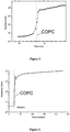
Figure 1 ) is a graphic that displays the resistance of the sensor material after step-wise increasing of humidity (RH). "A" indicates the humidity range usually present in airplanes."B" is the humidity range related to leaking aqueous liquids. "COPC" denotes the collapse of percolation conductivity (note the logarithmic scale). "T" is the possible detection threshold for the sensor (resistance grows by more than factor 1000 above humidity levels for normal aircraft operations). One can see that resistance variations due to varying humidities do not play any role at this scale. -
Figure 2 ) is a graphic that displays the resistance of TiCN/PVA Composite (45 VOl%) after hydration according to the first set-up. -
Figure 3 ) is a graphic that displays the resistance of the TiCN/PVA sensor (45 Vol%) after exposing the complete sensor to a sample of cola. -
Figure 4 is a drawing (Drawing 1 ) that displays an embodiment of a set-up of the floorbeam sensor, the length depend on requirements.- 1) Electrical core consisting of isolated electric wire (if possible already certified, e.g. ASNE 0261-CF24U)
- 2) Coat consisting of a nylon cord (already available as certified for floorbeams) impregnated with COPC-based sensing composite (approx, 100 micron thickness)
- 3) Eletrode to be connected with the COPC-based sensing composite (flex wires at the edges that are embedded in composite)
- 4) Shortcut between COPC-based sensing composite and electric core
-
Figure 5 is a drawing (Drawing 2 ) that displays an embodiment of deposition of the sensor in the floorbeam area (carpet, sealing systems and possible seat tracks are not shown).- 1) Floor plates
- 2) Floor beams
- 3) COPC-based sensor according to
Drawing 1 - 4) Cabin area
- 5) Acesss to cargo area
- 6) Electrodes for resistance measurements during maintenance
- In interpreting the claims, it should be understood that:
- a) the word "comprising" does not exclude the presence of other elements or acts than those listed in a given claim;
- b) the word "a" or "an" preceding an element does not exclude the presence of a plurality of such elements;
- c) any reference signs in the claims do not limit their scope;
- d) several "means" may be represented by the same item of hardware or function;
- g) any of the disclosed devices or portions thereof may be combined together or separated into further portions unless specifically stated otherwise;
- h) no specific sequence of acts is intended to be required unless specifically indicated; and
- i) the term "plurality of" an element includes two or more of the claimed element, and does not imply any particular range of number of elements; that is, a plurality of elements can be as few as two elements.
- The following detailed description of the invention refers to the accompanying drawings. The same reference numbers in different drawings identify the same or similar elements. Also, the following detailed description does not limit the invention. Instead, the scope of the invention is defined by the appended claims.
- An organo-ceramic composite consisting of titaniumcarbonitride (TiCN) powder (70/30) and polyvinyl alcohol (PVA) was produced. The components were weighted in an appropriate ratio, i.e. the concentration was chosen that the system was above the percolation threshold. The weight percentage of TiCN was in the range of 80 % which means that the volume fraction of TiCN was about 45% (density of TiCN about 6200 kg/m3 and PVA about 1300 kg/m3). Although, many different conducting compounds could be used for that sensor, a ceramic compound was selected because it is highly non-combustible in contrast to metal powders or graphite. This makes it a better material for aircraft applications. The matrix material (PVA), a polymer that is hygroscopic, i.e. it swells when it is exposed to a gaseous or liquid water phase. The components were mixed with an appropriate amount of water and sufficiently stirred until a homogenous substance was obtained.
- First set-up: Using a syringe (where the components were mixed and homogenized before), a wire was drawn on an acrylic plate (width of about 2 mm and a length of 150 mm). The material at both ends was in direct contact with respective electrodes. The thickness was slightly varying and estimated to be in the range of 500 micrometer. After a drying time of 16 hours, the resistance was measured with a digital multimeter to be in the range of 25 Ohm. This means an estimated specific resistance of about 3000 S/m. After exposing a part of the wire to a water drop, the resistance grows gradually until the range of 100 Ohm. From this point on, a resistance jump occurred until the range of 100 kOhm and that jump could finally be identified as the percolation threshold. The final resistance was reached at about 600 kOhm. The corresponding specific resistance can be estimated to be in the range of 2 S/m. The curve shown in the diagram (
figure 2 ) represents a kinetic process driven by the diffusion of water into the PVA matrix, i.e. when changing e.g. the mass of the sample, the initial water amount, exposed surface etc. the curve would change its kinetic parameters. Moreover, there are reasons to assume that the conductivity above the percolation threshold is not due to the percolated ceramic powder, but due to the ions dissolved in the aqueous phase that on its own has started to create a percolation network. - In a second set-up (
figure 3 ), a new sample was prepared with the same specifications such as described above. The starting substance (PVA+TiCN+H2O) was deposited on a cord of polyamides. That cord is sometimes implemented in aircraft floor beam sealings to enable a proper removal of the sealings between the floor beams during regular maintenance operations. Before deposition of the coating, an isolated electric wire was mounted into the core of the polyamide cord for the required electric connections. The composite was uniformly deposited on the polyamide cord using a specific vessel, i.e. deposition occurred when the cord was pulled through this vessel. At the edges, the composite was in contact with the flex wires of the electrical cable to establish a continuous circuit if resistance measurements are performed. We used about 4 g of raw material for the coating of 1 m of the polyamide cord. This gives an estimated thickness of the coating of about 400 micrometer. After 16 hours of drying, the resistance of 1 m sensor was in the range of 30 kOhm. After exposing the sensor to a coca-cola sample being a typical corrosive agent when spilled in aircraft areas, the resistance increases characteristically from about 30 kOhm to approximately 80 MOhm. Also here, the remaining resistance is most probably due to the ions dissolved in the aqueous phase that on its own has started to create a percolation network. - An important feature of this invention is the stability of the non-conducting state. Once, a relevant amount of liquid has entered the floor beam area, the sensor will absorb this liquid because ingressing liquid has to pass the positions of the sensor (
figures 4 and5 ,drawings 1 and 2). The absorbed liquid interrupts the electrical contact at a certain position. Due to the relatively high sample amount, the thickness of the coating and the length of the sensor, the drying time of the sensor is extremely long, especially in the confined space of floor plate joints in aircraft. It could be shown that in a lab experiment, the extraordinary high resistance will be maintained for many days. This means that the read-out of the sensor must not necessary be done during flight operations, but it can be done by electronic devices that are not part of the operational electronics. This essentially reduces the certification efforts when implementing the sensors reducing the costs of the overall system.
Claims (14)
- Use of a monitor for monitoring a floor or wall structure in a confined environment for hidden liquids, wherein the monitor comprises a sensing material (1) and a plurality of electrodes (3) for measuring resistance in the sensing material (1), wherein the sensing material (1), which is adapted to detect the hidden liquids, comprises a composite and the composite comprises particles or powder of an electrically-conductive material dispersed in a matrix which is lyophilic to the liquid, and wherein the concentration, dispersion and/or orientation of the electrically-conductive particles or powder are tailored such that the composite has a threshold of collapse of percolation conductivity and such that the resistance shows a transition through the threshold after entering of the liquid into the composite.
- Use of claim 1, wherein the confined environment is an aircraft and the floor or wall structure is a floor or wall beam.
- Use of claim 1 or 2, wherein the sensing material is arranged underneath a protective coating of the floor or wall structure.
- Use of any one preceding claim, wherein the lyophilic matrix is arranged to swell after the liquid has entered the composite.
- Use of any one preceding claim, wherein the lyophilic matrix is hydrophilic for sensing ingress of aqueous liquids.
- Use of any one preceding claim, wherein the monitor comprises an electrical core consisting of isolated electric wire and a coat consisting of a nylon cord impregnated with the composite, wherein one electrode is connected to the composite and wherein a shortcut is provided between the composite and the electrical core.
- Use of any one preceding claim, wherein the monitor is elongated and channelled in liquid collecting sinks in the floor or wall structure.
- Use of the monitor of any one preceding claim, wherein the composite comprises conductive particles selected from the group consisting of: metal particles, particles coated by a metal, carbon black particles, and particles of conductive ceramics.
- Use of claim 8, wherein the metal particles are nickel, copper or silver particles, or particles coated with nickel, copper or silver.
- Use of any one preceding claim, wherein the composite comprises titaniumcarbonitride (TiCN) powder.
- Use of any one preceding claim, wherein the matrix comprises a polymer that is hygroscopic.
- Use of any one preceding claim, wherein the matrix comprises polyvinyl alcohol.
- Use of any one preceding claim, wherein the matrix is formed of a polymer having a density between 0.5 and 1.5 g/cm3.
- Use of any one preceding claim, wherein the floor or wall structure comprises or is essentially composed of aluminium alloys.
Applications Claiming Priority (3)
| Application Number | Priority Date | Filing Date | Title |
|---|---|---|---|
| US39951410P | 2010-07-12 | 2010-07-12 | |
| GBGB1107664.3A GB201107664D0 (en) | 2011-05-09 | 2011-05-09 | Sensor for detecting liquid spilling |
| PCT/BE2011/000046 WO2012006692A1 (en) | 2010-07-12 | 2011-07-12 | Sensor for detecting liquid spilling |
Publications (2)
| Publication Number | Publication Date |
|---|---|
| EP2593778A1 EP2593778A1 (en) | 2013-05-22 |
| EP2593778B1 true EP2593778B1 (en) | 2018-04-11 |
Family
ID=44243788
Family Applications (1)
| Application Number | Title | Priority Date | Filing Date |
|---|---|---|---|
| EP11760391.0A Active EP2593778B1 (en) | 2010-07-12 | 2011-07-12 | Use of a sensor for detecting liquid spilling |
Country Status (4)
| Country | Link |
|---|---|
| US (1) | US8963565B2 (en) |
| EP (1) | EP2593778B1 (en) |
| GB (1) | GB201107664D0 (en) |
| WO (1) | WO2012006692A1 (en) |
Families Citing this family (9)
| Publication number | Priority date | Publication date | Assignee | Title |
|---|---|---|---|---|
| BRPI0409322B8 (en) | 2003-04-11 | 2021-05-25 | Antriabio Inc | method for preparing an insulin-polymer conjugate |
| GB201017238D0 (en) * | 2010-10-13 | 2010-11-24 | Univ Leuven Kath | Sensor for planes |
| US20140317954A1 (en) * | 2012-05-10 | 2014-10-30 | Norgren Automation Solutions, Llc | Method and apparatus for automatically drying wet floors |
| CA2873102A1 (en) * | 2012-05-10 | 2013-11-14 | Norgren Automation Solutions, Llc | Method and apparatus for automatically drying wet floors |
| RU2603555C1 (en) * | 2015-09-30 | 2016-11-27 | Федеральное государственное бюджетное образовательное учреждение высшего образования "Московский технологический университет" | Sensor cable |
| WO2018126326A1 (en) * | 2017-01-06 | 2018-07-12 | Direct-C Limited | Polymeric nanocomposite based sensor and coating systems and their applications |
| US10490430B2 (en) * | 2017-10-30 | 2019-11-26 | Taiwan Semiconductor Manufacturing Co., Ltd. | Flexible linear sensor |
| CN110687378A (en) * | 2019-10-17 | 2020-01-14 | 中国人民解放军海军工程大学 | Dissimilar metal electrical isolation monitoring device |
| US11815428B1 (en) * | 2021-07-29 | 2023-11-14 | ZT Group Int'l, Inc. | Direct leak detection for liquid cooled servers |
Family Cites Families (10)
| Publication number | Priority date | Publication date | Assignee | Title |
|---|---|---|---|---|
| JPS6156952A (en) * | 1984-08-28 | 1986-03-22 | Sharp Corp | Moisture sensitive resistor element |
| US5256574A (en) * | 1989-06-26 | 1993-10-26 | Bell Communications Research, Inc. | Method for selective detection of liquid phase hydrocarbons |
| JP3625348B2 (en) | 1996-12-10 | 2005-03-02 | Tdk株式会社 | Moisture sensitive element |
| TW571093B (en) | 1998-12-28 | 2004-01-11 | Tdk Corp | Moisture sensor |
| US6717664B2 (en) | 2002-06-14 | 2004-04-06 | The Boeing Company | System and method for inspecting a beam using micro fiber-optic technology |
| US20050150778A1 (en) * | 2002-11-18 | 2005-07-14 | Lewis Nathan S. | Use of basic polymers in carbon black composite vapor detectors to obtain enhanced sensitivity and classification performance for volatile fatty acids |
| US6894512B2 (en) * | 2003-03-24 | 2005-05-17 | Israel Aircraft Industries Ltd. | Method for detecting hidden corrosion and a sensor for use in the same |
| NO327090B1 (en) * | 2007-06-28 | 2009-04-20 | Asle Ingmar Johnsen | detector System |
| GB0912444D0 (en) * | 2009-07-17 | 2009-08-26 | Kitchener Renato | Differential, low conductivity to iec61158-2 physical layer converter |
| WO2012054894A2 (en) * | 2010-10-21 | 2012-04-26 | Raymond & Lae Engineering, Inc. | Liquid detection cable |
-
2011
- 2011-05-09 GB GBGB1107664.3A patent/GB201107664D0/en not_active Ceased
- 2011-07-12 US US13/809,517 patent/US8963565B2/en active Active
- 2011-07-12 EP EP11760391.0A patent/EP2593778B1/en active Active
- 2011-07-12 WO PCT/BE2011/000046 patent/WO2012006692A1/en not_active Ceased
Also Published As
| Publication number | Publication date |
|---|---|
| US8963565B2 (en) | 2015-02-24 |
| WO2012006692A1 (en) | 2012-01-19 |
| GB201107664D0 (en) | 2011-06-22 |
| EP2593778A1 (en) | 2013-05-22 |
| US20130113505A1 (en) | 2013-05-09 |
Similar Documents
| Publication | Publication Date | Title |
|---|---|---|
| US8963565B2 (en) | Sensor for detecting liquid spilling | |
| US8400171B2 (en) | Transmission line moisture sensor | |
| EP2063243B1 (en) | Smart coating for damage detected information, inspecting device and damage inspecting method using said coating | |
| EP3635347B1 (en) | Fuel tank with integrated level sensors, in particular for aerial vehicles | |
| US11614378B2 (en) | Polymeric nanocomposite based sensor and coating systems and their applications | |
| US6894512B2 (en) | Method for detecting hidden corrosion and a sensor for use in the same | |
| WO1993024819A1 (en) | Detecting degradation of non-conductive inert wall layers in fluid containers | |
| CA3074601A1 (en) | Hydrocarbon leak detection system and method for pipelines | |
| KR101489891B1 (en) | Marine HNS spill detector using Indium-tin-oxide film sensor | |
| Pfeiffer et al. | Leakage monitoring using percolation sensors for revealing structural damage in engineering structures | |
| HK1185413A (en) | Use of a sensor for detecting liquid spilling | |
| HK1185413B (en) | Use of a sensor for detecting liquid spilling | |
| EP1955377B1 (en) | Sensor for detecting organic liquids | |
| US7421883B2 (en) | Capacitive vapor sensor | |
| Pfeiffer et al. | Liquid detection in confined aircraft structures based on lyotropic percolation thresholds | |
| US3715598A (en) | Integral fault detection system for operating electronics equipment | |
| Pfeiffer et al. | Structural Health Monitoring in an Operational Airliner: An Intermediate Report on Leakage Monitoring with Percolation Sensors | |
| EP2627562B1 (en) | Sensor for detecting hydraulic liquids in aircraft | |
| Pfeiffer et al. | Sigmoidal Sensing Devices for Monitoring to improve Maintenance Operations in Aeronautics | |
| Pfeiffer et al. | The potential of highly non-linear sensing systems in engineering structures–operating applications in civil aircraft and chemical installations | |
| Pfeiffer et al. | Project Overview AISHA-II and Detection of Corrosive and Hydraulic Liquids by Gauges Based On the Collapse of Percolation Conductivity | |
| Schoess | Conductive Polymer Sensor Arrays-A New Frontier Technology for CBM | |
| WO2015182825A1 (en) | Bonded structure damage detection device | |
| Pfeiffer et al. | Highly non-linear sensing devices in structural health monitoring | |
| Pfeiffer et al. | Monitoring of structures and systems of aircraft by highly non‐linear sensing devices |
Legal Events
| Date | Code | Title | Description |
|---|---|---|---|
| PUAI | Public reference made under article 153(3) epc to a published international application that has entered the european phase |
Free format text: ORIGINAL CODE: 0009012 |
|
| 17P | Request for examination filed |
Effective date: 20130206 |
|
| AK | Designated contracting states |
Kind code of ref document: A1 Designated state(s): AL AT BE BG CH CY CZ DE DK EE ES FI FR GB GR HR HU IE IS IT LI LT LU LV MC MK MT NL NO PL PT RO RS SE SI SK SM TR |
|
| DAX | Request for extension of the european patent (deleted) | ||
| REG | Reference to a national code |
Ref country code: HK Ref legal event code: DE Ref document number: 1185413 Country of ref document: HK |
|
| GRAP | Despatch of communication of intention to grant a patent |
Free format text: ORIGINAL CODE: EPIDOSNIGR1 |
|
| INTG | Intention to grant announced |
Effective date: 20171102 |
|
| GRAS | Grant fee paid |
Free format text: ORIGINAL CODE: EPIDOSNIGR3 |
|
| GRAA | (expected) grant |
Free format text: ORIGINAL CODE: 0009210 |
|
| AK | Designated contracting states |
Kind code of ref document: B1 Designated state(s): AL AT BE BG CH CY CZ DE DK EE ES FI FR GB GR HR HU IE IS IT LI LT LU LV MC MK MT NL NO PL PT RO RS SE SI SK SM TR |
|
| REG | Reference to a national code |
Ref country code: GB Ref legal event code: FG4D |
|
| REG | Reference to a national code |
Ref country code: CH Ref legal event code: EP |
|
| REG | Reference to a national code |
Ref country code: AT Ref legal event code: REF Ref document number: 988585 Country of ref document: AT Kind code of ref document: T Effective date: 20180415 |
|
| REG | Reference to a national code |
Ref country code: IE Ref legal event code: FG4D |
|
| REG | Reference to a national code |
Ref country code: DE Ref legal event code: R096 Ref document number: 602011047420 Country of ref document: DE |
|
| REG | Reference to a national code |
Ref country code: FR Ref legal event code: PLFP Year of fee payment: 8 |
|
| REG | Reference to a national code |
Ref country code: NL Ref legal event code: MP Effective date: 20180411 |
|
| REG | Reference to a national code |
Ref country code: LT Ref legal event code: MG4D |
|
| PG25 | Lapsed in a contracting state [announced via postgrant information from national office to epo] |
Ref country code: NL Free format text: LAPSE BECAUSE OF FAILURE TO SUBMIT A TRANSLATION OF THE DESCRIPTION OR TO PAY THE FEE WITHIN THE PRESCRIBED TIME-LIMIT Effective date: 20180411 |
|
| PG25 | Lapsed in a contracting state [announced via postgrant information from national office to epo] |
Ref country code: NO Free format text: LAPSE BECAUSE OF FAILURE TO SUBMIT A TRANSLATION OF THE DESCRIPTION OR TO PAY THE FEE WITHIN THE PRESCRIBED TIME-LIMIT Effective date: 20180711 Ref country code: PL Free format text: LAPSE BECAUSE OF FAILURE TO SUBMIT A TRANSLATION OF THE DESCRIPTION OR TO PAY THE FEE WITHIN THE PRESCRIBED TIME-LIMIT Effective date: 20180411 Ref country code: ES Free format text: LAPSE BECAUSE OF FAILURE TO SUBMIT A TRANSLATION OF THE DESCRIPTION OR TO PAY THE FEE WITHIN THE PRESCRIBED TIME-LIMIT Effective date: 20180411 Ref country code: LT Free format text: LAPSE BECAUSE OF FAILURE TO SUBMIT A TRANSLATION OF THE DESCRIPTION OR TO PAY THE FEE WITHIN THE PRESCRIBED TIME-LIMIT Effective date: 20180411 Ref country code: AL Free format text: LAPSE BECAUSE OF FAILURE TO SUBMIT A TRANSLATION OF THE DESCRIPTION OR TO PAY THE FEE WITHIN THE PRESCRIBED TIME-LIMIT Effective date: 20180411 Ref country code: SE Free format text: LAPSE BECAUSE OF FAILURE TO SUBMIT A TRANSLATION OF THE DESCRIPTION OR TO PAY THE FEE WITHIN THE PRESCRIBED TIME-LIMIT Effective date: 20180411 Ref country code: BG Free format text: LAPSE BECAUSE OF FAILURE TO SUBMIT A TRANSLATION OF THE DESCRIPTION OR TO PAY THE FEE WITHIN THE PRESCRIBED TIME-LIMIT Effective date: 20180711 Ref country code: FI Free format text: LAPSE BECAUSE OF FAILURE TO SUBMIT A TRANSLATION OF THE DESCRIPTION OR TO PAY THE FEE WITHIN THE PRESCRIBED TIME-LIMIT Effective date: 20180411 |
|
| PG25 | Lapsed in a contracting state [announced via postgrant information from national office to epo] |
Ref country code: LV Free format text: LAPSE BECAUSE OF FAILURE TO SUBMIT A TRANSLATION OF THE DESCRIPTION OR TO PAY THE FEE WITHIN THE PRESCRIBED TIME-LIMIT Effective date: 20180411 Ref country code: RS Free format text: LAPSE BECAUSE OF FAILURE TO SUBMIT A TRANSLATION OF THE DESCRIPTION OR TO PAY THE FEE WITHIN THE PRESCRIBED TIME-LIMIT Effective date: 20180411 Ref country code: GR Free format text: LAPSE BECAUSE OF FAILURE TO SUBMIT A TRANSLATION OF THE DESCRIPTION OR TO PAY THE FEE WITHIN THE PRESCRIBED TIME-LIMIT Effective date: 20180712 Ref country code: HR Free format text: LAPSE BECAUSE OF FAILURE TO SUBMIT A TRANSLATION OF THE DESCRIPTION OR TO PAY THE FEE WITHIN THE PRESCRIBED TIME-LIMIT Effective date: 20180411 |
|
| REG | Reference to a national code |
Ref country code: AT Ref legal event code: MK05 Ref document number: 988585 Country of ref document: AT Kind code of ref document: T Effective date: 20180411 |
|
| PG25 | Lapsed in a contracting state [announced via postgrant information from national office to epo] |
Ref country code: PT Free format text: LAPSE BECAUSE OF FAILURE TO SUBMIT A TRANSLATION OF THE DESCRIPTION OR TO PAY THE FEE WITHIN THE PRESCRIBED TIME-LIMIT Effective date: 20180813 |
|
| REG | Reference to a national code |
Ref country code: DE Ref legal event code: R097 Ref document number: 602011047420 Country of ref document: DE |
|
| PG25 | Lapsed in a contracting state [announced via postgrant information from national office to epo] |
Ref country code: AT Free format text: LAPSE BECAUSE OF FAILURE TO SUBMIT A TRANSLATION OF THE DESCRIPTION OR TO PAY THE FEE WITHIN THE PRESCRIBED TIME-LIMIT Effective date: 20180411 Ref country code: DK Free format text: LAPSE BECAUSE OF FAILURE TO SUBMIT A TRANSLATION OF THE DESCRIPTION OR TO PAY THE FEE WITHIN THE PRESCRIBED TIME-LIMIT Effective date: 20180411 Ref country code: SK Free format text: LAPSE BECAUSE OF FAILURE TO SUBMIT A TRANSLATION OF THE DESCRIPTION OR TO PAY THE FEE WITHIN THE PRESCRIBED TIME-LIMIT Effective date: 20180411 Ref country code: RO Free format text: LAPSE BECAUSE OF FAILURE TO SUBMIT A TRANSLATION OF THE DESCRIPTION OR TO PAY THE FEE WITHIN THE PRESCRIBED TIME-LIMIT Effective date: 20180411 Ref country code: CZ Free format text: LAPSE BECAUSE OF FAILURE TO SUBMIT A TRANSLATION OF THE DESCRIPTION OR TO PAY THE FEE WITHIN THE PRESCRIBED TIME-LIMIT Effective date: 20180411 Ref country code: EE Free format text: LAPSE BECAUSE OF FAILURE TO SUBMIT A TRANSLATION OF THE DESCRIPTION OR TO PAY THE FEE WITHIN THE PRESCRIBED TIME-LIMIT Effective date: 20180411 |
|
| PLBE | No opposition filed within time limit |
Free format text: ORIGINAL CODE: 0009261 |
|
| STAA | Information on the status of an ep patent application or granted ep patent |
Free format text: STATUS: NO OPPOSITION FILED WITHIN TIME LIMIT |
|
| PG25 | Lapsed in a contracting state [announced via postgrant information from national office to epo] |
Ref country code: IT Free format text: LAPSE BECAUSE OF FAILURE TO SUBMIT A TRANSLATION OF THE DESCRIPTION OR TO PAY THE FEE WITHIN THE PRESCRIBED TIME-LIMIT Effective date: 20180411 Ref country code: SM Free format text: LAPSE BECAUSE OF FAILURE TO SUBMIT A TRANSLATION OF THE DESCRIPTION OR TO PAY THE FEE WITHIN THE PRESCRIBED TIME-LIMIT Effective date: 20180411 |
|
| REG | Reference to a national code |
Ref country code: CH Ref legal event code: PL |
|
| 26N | No opposition filed |
Effective date: 20190114 |
|
| PG25 | Lapsed in a contracting state [announced via postgrant information from national office to epo] |
Ref country code: LU Free format text: LAPSE BECAUSE OF NON-PAYMENT OF DUE FEES Effective date: 20180712 Ref country code: MC Free format text: LAPSE BECAUSE OF FAILURE TO SUBMIT A TRANSLATION OF THE DESCRIPTION OR TO PAY THE FEE WITHIN THE PRESCRIBED TIME-LIMIT Effective date: 20180411 |
|
| REG | Reference to a national code |
Ref country code: IE Ref legal event code: MM4A |
|
| PG25 | Lapsed in a contracting state [announced via postgrant information from national office to epo] |
Ref country code: LI Free format text: LAPSE BECAUSE OF NON-PAYMENT OF DUE FEES Effective date: 20180731 Ref country code: IE Free format text: LAPSE BECAUSE OF NON-PAYMENT OF DUE FEES Effective date: 20180712 Ref country code: CH Free format text: LAPSE BECAUSE OF NON-PAYMENT OF DUE FEES Effective date: 20180731 |
|
| PG25 | Lapsed in a contracting state [announced via postgrant information from national office to epo] |
Ref country code: SI Free format text: LAPSE BECAUSE OF FAILURE TO SUBMIT A TRANSLATION OF THE DESCRIPTION OR TO PAY THE FEE WITHIN THE PRESCRIBED TIME-LIMIT Effective date: 20180411 |
|
| PG25 | Lapsed in a contracting state [announced via postgrant information from national office to epo] |
Ref country code: MT Free format text: LAPSE BECAUSE OF NON-PAYMENT OF DUE FEES Effective date: 20180712 |
|
| PG25 | Lapsed in a contracting state [announced via postgrant information from national office to epo] |
Ref country code: TR Free format text: LAPSE BECAUSE OF FAILURE TO SUBMIT A TRANSLATION OF THE DESCRIPTION OR TO PAY THE FEE WITHIN THE PRESCRIBED TIME-LIMIT Effective date: 20180411 |
|
| PG25 | Lapsed in a contracting state [announced via postgrant information from national office to epo] |
Ref country code: HU Free format text: LAPSE BECAUSE OF FAILURE TO SUBMIT A TRANSLATION OF THE DESCRIPTION OR TO PAY THE FEE WITHIN THE PRESCRIBED TIME-LIMIT; INVALID AB INITIO Effective date: 20110712 |
|
| PG25 | Lapsed in a contracting state [announced via postgrant information from national office to epo] |
Ref country code: MK Free format text: LAPSE BECAUSE OF NON-PAYMENT OF DUE FEES Effective date: 20180411 Ref country code: CY Free format text: LAPSE BECAUSE OF FAILURE TO SUBMIT A TRANSLATION OF THE DESCRIPTION OR TO PAY THE FEE WITHIN THE PRESCRIBED TIME-LIMIT Effective date: 20180411 |
|
| PG25 | Lapsed in a contracting state [announced via postgrant information from national office to epo] |
Ref country code: IS Free format text: LAPSE BECAUSE OF FAILURE TO SUBMIT A TRANSLATION OF THE DESCRIPTION OR TO PAY THE FEE WITHIN THE PRESCRIBED TIME-LIMIT Effective date: 20180811 |
|
| PGFP | Annual fee paid to national office [announced via postgrant information from national office to epo] |
Ref country code: GB Payment date: 20250619 Year of fee payment: 15 |
|
| PGFP | Annual fee paid to national office [announced via postgrant information from national office to epo] |
Ref country code: BE Payment date: 20250619 Year of fee payment: 15 |
|
| PGFP | Annual fee paid to national office [announced via postgrant information from national office to epo] |
Ref country code: FR Payment date: 20250619 Year of fee payment: 15 |
|
| PGFP | Annual fee paid to national office [announced via postgrant information from national office to epo] |
Ref country code: DE Payment date: 20250620 Year of fee payment: 15 |