EP2593744B1 - Optoelectronic digital apparatus for assisting an operator in determining the shooting attitude to be given to a hand-held grenade launcher so as to strike a moving target, and respective operation method - Google Patents
Optoelectronic digital apparatus for assisting an operator in determining the shooting attitude to be given to a hand-held grenade launcher so as to strike a moving target, and respective operation method Download PDFInfo
- Publication number
- EP2593744B1 EP2593744B1 EP11768075.1A EP11768075A EP2593744B1 EP 2593744 B1 EP2593744 B1 EP 2593744B1 EP 11768075 A EP11768075 A EP 11768075A EP 2593744 B1 EP2593744 B1 EP 2593744B1
- Authority
- EP
- European Patent Office
- Prior art keywords
- pitch
- grenade
- projectile
- imp
- target
- Prior art date
- Legal status (The legal status is an assumption and is not a legal conclusion. Google has not performed a legal analysis and makes no representation as to the accuracy of the status listed.)
- Active
Links
Images



Classifications
-
- F—MECHANICAL ENGINEERING; LIGHTING; HEATING; WEAPONS; BLASTING
- F41—WEAPONS
- F41G—WEAPON SIGHTS; AIMING
- F41G1/00—Sighting devices
- F41G1/46—Sighting devices for particular applications
- F41G1/48—Sighting devices for particular applications for firing grenades from rifles
-
- F—MECHANICAL ENGINEERING; LIGHTING; HEATING; WEAPONS; BLASTING
- F41—WEAPONS
- F41G—WEAPON SIGHTS; AIMING
- F41G1/00—Sighting devices
- F41G1/46—Sighting devices for particular applications
- F41G1/473—Sighting devices for particular applications for lead-indicating or range-finding, e.g. for use with rifles or shotguns
-
- F—MECHANICAL ENGINEERING; LIGHTING; HEATING; WEAPONS; BLASTING
- F41—WEAPONS
- F41G—WEAPON SIGHTS; AIMING
- F41G3/00—Aiming or laying means
- F41G3/06—Aiming or laying means with rangefinder
-
- F—MECHANICAL ENGINEERING; LIGHTING; HEATING; WEAPONS; BLASTING
- F41—WEAPONS
- F41G—WEAPON SIGHTS; AIMING
- F41G3/00—Aiming or laying means
- F41G3/14—Indirect aiming means
- F41G3/16—Sighting devices adapted for indirect laying of fire
Definitions
- the present invention relates to an optoelectronic digital apparatus for assisting an operator in determining the shooting attitude to be given to a hand-held grenade launcher so as to strike a moving target and to a respective operation method.
- a weapon system that comprises, not only a traditional hand-held weapon such as a rifle, but also a grenade launcher, which is coupled to the hand-held weapon to enable the operator to launch towards a moving target high caliber ammunition, greater than or equal to 40 mm, which as known, is indicated by the word "grenade”.
- the probability of failure in hitting a moving target with a grenade launched from a weapon system of the type described above crucially depends on determining the correct shooting attitude to be given to a grenade launcher by the operator.
- Such an assessment results, however, to be extremely complex and therefore susceptible to errors as the operator must make, extremely quickly, especially in combat scenarios, a visual estimate of the distance from the moving target, a visual estimate of the angle of the site where the moving target is, and determine the shooting attitude to be given to the grenade launcher taking into account the movement of the target, the distance, the angle and the trajectory of the grenade, which trajectory, as known, results to be particularly difficult to determine.
- EP 0785 406 A2 relates to a improved method and device for aiming and firing a rifle-mounted grenade launcher without having to approximate the range of a target and then manually adjust the position of subsequently fired grenades.
- the grenadier initiates the process by pointing the grenade launcher at the stationary target.
- the range and azimuth of the stationary target are determined by a microprocessor controlled laser range finder/digital compass combination.
- a ballistic solution is calculated by the microprocessor and the superelevation required to place the grenade on stationary target is displayed on one of several video displays.
- the aim of the present invention is therefore to provide an optoelectronic digital apparatus adapted for assisting an operator both in determining the shooting attitude to be given to the hand-held grenade launcher and in the spatial orientation to be given, moment by moment, to the grenade launcher according to the given shooting attitude responding to the guidance of the grenade launcher by the operator itself, so as to increase the probability of success of striking a moving target with a grenade.
- an optoelectronic digital apparatus for assisting an operator in determining the shooting attitude to be given to a hand-held grenade launcher so as to strike a moving target with a grenade, as stated in claim 1 and preferably, but not necessarily, in any of the claims depending directly or indirectly from claim 1.
- a method for assisting an operator is further provided, by way of an optoelectronic digital apparatus, in determining the shooting attitude to be given to a hand-held grenade launcher so as to strike a moving target, by way of a grenade according to that stated in claim 8 and preferably, but not necessarily, in any of the claims depending directly or indirectly from claim 8.
- a computer product loadable onto the memory of an electronic calculator for assisting an operator, when implemented by the electronic computer itself, in determining the shooting attitude to be given to a hand-held grenade launcher so as to strike a moving target in accordance to that stated in claim 15.
- the assisting optoelectronic apparatus 2 is also configured so as to communicate to the operator, moment by moment, the angular pitch and heading movements to be given to the grenade launcher 1 to strike the target k, based on the differences in space present between the determined shooting attitude and the instantaneous attitude given to the grenade launcher 1 by the operator and the given next motion of the target k.
- the grenade launcher 1 can be preferably, but not necessarily, mounted on a hand-held weapon 3, for example, a rifle and in the example shown in Figure 1 comprises a grenade launch tube 4 presenting a longitudinal axis L coincident and integral with a first Cartesian axis X BODY of a predetermined body reference system ⁇ BODY associated with the grenade launcher 1, and presenting a second Cartesian axis Y BODY , orthogonal to the first Cartesian axis X BODY , and a third Cartesian axis Z BODY orthogonal to the first X BODY and to the second Cartesian axis Y BODY .
- the grenade launcher 1 also comprises a pointing device 5 adapted to enable the operator to aim at the moving target k and then place the grenade launcher 1 in a pointing attitude on the basis of the display of the target k itself.
- the pointing device 5 is of a known type and therefore will not be further described except to clarify that it can be configured so that, for example, in the pointing attitude, the longitudinal axis L of the grenade launch tube 4 intersects the target k.
- the assisting optoelectronic apparatus 2 comprises an electronic distance measuring device 6, which is configured to measure the distance Dist target of the target K from the grenade launcher 1; and an electronic attitude measuring device 7, which is configured for determining the instantaneous attitude of the grenade launcher 1, i.e. the pitch angle ⁇ pitch and the heading angle ⁇ head that characterize the attitude itself.
- the assisting optoelectronic apparatus 2 also comprises a user interface 8 by which an operator is able to issue commands to the assisting optoelectronic apparatus 2 and receives indications on variation in attitude ⁇ pitch and ⁇ head to be given to the grenade launcher 1 to strike the moving target k.
- the assisting optoelectronic apparatus 2 also comprises an electronic processing unit 9, which is configured so as to compute the pitch angle ⁇ pitch, and the heading angle ⁇ f head that characterize the shooting attitude, and communicates to the operator, by way of the user interface 8 and, in response to the movement of the grenade launcher 1 itself by the operator, the variation in attitude ⁇ pitcht ⁇ head to be given to the grenade launcher 1 to orientate it so as to strike the moving target k.
- an electronic processing unit 9 which is configured so as to compute the pitch angle ⁇ pitch, and the heading angle ⁇ f head that characterize the shooting attitude, and communicates to the operator, by way of the user interface 8 and, in response to the movement of the grenade launcher 1 itself by the operator, the variation in attitude ⁇ pitcht ⁇ head to be given to the grenade launcher 1 to orientate it so as to strike the moving target k.
- the assisting optoelectronic apparatus 2 further comprises a memory unit 10 containing a series of ammunition-data indicating a plurality of different grenade types employable in the grenade launcher 1.
- the memory unit 10 further contains, for each type of grenade, a series of ballistic data associated with the grenade itself, such as: the frontal area S of the grenade i.e. the area of the front surface of the grenade itself; the mass m of the grenade; the coefficient of aerodynamic resistance Cd of the grenade; the lift coefficient Cl of the grenade; the launching speed of the grenade Vin; a coefficient Vin1 correlated with the launching speed variation Vin of the grenade at changing temperature T.
- a series of ballistic data associated with the grenade itself such as: the frontal area S of the grenade i.e. the area of the front surface of the grenade itself; the mass m of the grenade; the coefficient of aerodynamic resistance Cd of the grenade; the lift coefficient Cl of the grenade; the launching speed of the grenade Vin; a coefficient Vin1 correlated with the launching speed variation Vin of the
- the memory unit 10 is also adapted for further storing: environmental data indicating the atmospheric pressure p, the thermodynamic constant of air R; and precision data indicating a minimum desired precision err y of impact of the grenade on the target K along a vertical axis (e.g. the axis Y in Figure 1 ), which is orthogonal to a flat Earth's ground reference surface, and a minimum desired precision err x of impact of the grenade on the target K along a horizontal axis (e.g. the axis X in Figure 1 ) parallel to a flat Earth's ground surface in the shooting direction (errors related to the action range of the grenade in use).
- environmental data indicating the atmospheric pressure p, the thermodynamic constant of air R
- precision data indicating a minimum desired precision err y of impact of the grenade on the target K along a vertical axis (e.g. the axis Y in Figure 1 ), which is orthogonal to a flat Earth
- the assisting optoelectronic apparatus 2 also comprises sensors 11 adapted to measure the air temperature T, corresponding in the initial step, to the temperature of the grenade.
- the distance measuring device 6 may comprise, for example, a LASER rangefinder (acronym for Light Amplification by Stimulated Emission of Radiation), which is configured so as to emit laser pulses towards the target determining the distance Dist target of the target from the grenade launcher 1 in function of the "flight time" t flight of the LASER pulse.
- a LASER rangefinder ancronym for Light Amplification by Stimulated Emission of Radiation
- the electronic attitude measuring device 7 in the example shown in Figure 2 it comprises an inertial electronic platform 12 configured to provide in output the acceleration components Ax, Ay, Az and angular velocity components Gx, Gy and Gz of the grenade launcher 1 determined with respect to the body reference system ⁇ BODY .
- the inertial electronic platform 12 conveniently comprises one or more accelerometers (not illustrated), for example, a dual-axis accelerometer and two single-axis accelerometers, presenting two measuring axes arranged along the axes X BODY and Y BODY of the body reference system ⁇ BODY ; and one or more gyroscopes presenting a total of three measuring axes arranged parallel to the axes X BODY , Y BODY and Z BODY of the body reference system ⁇ BODY .
- accelerometers not illustrated
- a dual-axis accelerometer and two single-axis accelerometers presenting two measuring axes arranged along the axes X BODY and Y BODY of the body reference system ⁇ BODY .
- gyroscopes presenting a total of three measuring axes arranged parallel to the axes X BODY , Y BODY and Z BODY of the body reference system ⁇ BODY .
- the attitude measuring device 7 also comprises a computing module 13 receiving the input acceleration components Ax, Ay, Az, and the angular velocity components Gx, Gy and Gz measured by the electronic inertial platform 12 thus processing them to provide in output the pitch angle ⁇ pitch , and the heading angle ⁇ head .
- the pitch ⁇ pitch and heading ⁇ head angles can be conveniently determined by the computing module 13 by way of, for example, the computing method described in the patent application filed in Italy on April 12, 2010 with the No. TV2010A000060, which is here incorporated as reference.
- the user interface 8 comprising a screen or display 14 to visualize one or more graphic interfaces, a control device 15, and preferably but not necessarily a voice message generating device 16.
- the electronic processing unit 9 can be configured so as to ensure that the display 14 and/or the voice message generating device 16 notifies the operator attitude variations ⁇ pitch and ⁇ head to be given to the grenade launcher 1, while the control device 15 may comprise a keyboard provided with a set of keys through which the operator imparts commands to the assisting optoelectronic apparatus 2.
- the display 14 is conveniently of an OLED type (acronym for Organic Light Emitting Diode) while the electronic processing unit 9 is configured to ensure that also the display 14 visualizes a supporting graphical interface 14a representing the attitude variation ⁇ pitch and ⁇ head to be given to the grenade launcher 1 to strike the moving target k.
- OLED Organic Light Emitting Diode
- the electronic processing unit 9 is configured to ensure that the assisting graphical interface 14a visualized by the display 14 comprises a graphical attitude cross 18 provided with a plurality of luminous segments arranged aligned one after the other so as to form a first and a second attitude branch which are mutually orthogonal and intersect a common central point.
- the electronic processing unit 9 is configured to switch on/off:
- the attitude branch 20 is subdivided in correspondence to the midpoint in a first 20a and in a second luminous branch 20b, wherein the first luminous branch 20a comprises a predetermined number N1 of segments adapted to be switched on/off in function of the negative variation of the pitch angle ⁇ pitch , while the second luminous branch 20b comprises a predetermined number N1 of segments adapted for being switched on/off in function of the negative variation of the pitch angle ⁇ pitch .
- the second luminous branch 21 is in turn divided in correspondence to the midpoint in a first 21a and in a second luminous branch 21b, wherein the first luminous branch 21a comprises a predetermined number N3 of segments adapted for being switched on/off in function of the negative variation of the heading angle ⁇ head , while the second luminous branch 21b comprises a predetermined number N4 of segments adapted for being switched on/off in function of the positive variation of the heading angle ⁇ head .
- the general attitude of the grenade launcher 1 is characterized by a pitch angle ⁇ PITCH (t i ) and a heading angle ⁇ HEAD (t i ), wherein the pitch angle ⁇ PITCH (t i ) corresponds to the angle present between the first Cartesian axis X BODY and a reference plane lying on Earth's ground level; while the heading angle ⁇ HEAD (t i ) corresponds to the azimuth angle present between the first Cartesian axis Y BODY and Earth's geographic NORTH.
- the voice message generating device 16 it can be configured so as to communicate voice messages containing the attitude variation ⁇ head and ⁇ pitch to be given to the grenade launcher 1 to strike the moving target.
- the voice message generating device 16 can comprise, for example, an electronic digital unit configured to produce digital voice messages and a loudspeaker such as a headset connected to the electronic digital unit and usable by the operator for listening to information relative to the attitude variation ⁇ head and ⁇ pitch to be given to the grenade launcher 1.
- the electronic processing unit 9 can comprise a microprocessor receiving in input: pitch ⁇ pitch and heading ⁇ head angles; the distance Dist target of the target; and commands given by the user by way of the control device 15.
- the electronic processing unit 9 also receives a series of data indicative of the type of grenade to be launched such as: the frontal area S, the mass m, the coefficient of aerodynamic resistance Cd; the lift coefficient C1; the speed of release Vin of the grenade; the coefficient of variation Vin1.
- the electronic processing unit 9 further receives a series of data indicative of the atmospheric pressure p; of the thermodynamic constant of the air R; and data indicative of minimum desired precision impact err y and err x along the X and Y axis respectively.
- the electronic processing unit 9 is adapted to implement a computing method that processes the input variables listed above to communicate to the operator in output, moment by moment, the attitude variation ⁇ pitch and ⁇ head to be given to the grenade launcher 1 for achieving the correct shooting attitude necessary to strike a moving target k.
- the electronic processing unit 9 is adapted to vary the number N1 and/or N2 of switching on/off of the segments contained in the first luminous branch 20, and the number N3 and/or N4 of switching on/off of the segments contained in the second luminous branch 21, so as to conveniently visually notify the operator the angle to be given so as to place the grenade launcher 1 in the shooting attitude.
- the configuration/setting of the assisting optoelectronic apparatus 2 can provide that: the electronic processing unit 9 notifies the operator by way of the user interface 8 the different types of grenades usable contained in the memory unit 10 and determines in the memory unit 10 itself the data that characterize the grenade ballistics, in response to a selection command of the grenade given by the operator.
- the operator selects, by way of the user interface 8, the type of shooting trajectory to be given to the grenade, which may correspond to a first type, later indicated with “flat shot” an example of which is shown in Figure 9 , or a second type, later indicated with “non-flat shot” an example of which is shown in Figure 10 (block 100).
- the method essentially provides a series of data acquisition operations, and a series of computing attitude operations to be given to the grenade launcher 1 to strike the moving target k on the basis of the acquired data.
- the method preferably, but not necessarily, provides that the electronic processing unit 9 communicates to the operator through the user interface 8 a request of pointing/tracking of the target k by way of the grenade launcher for a given time interval.
- the memory unit 10 can be conveniently structured so as to comprise a circular memory buffer 10a (shown in Figure 1 ) in which the sampled data Dist targed ( tci ⁇ pitch (t ci ), ⁇ head (t ci ) acquired during sampling stored.
- the electronic processing unit 9 temporally sorts the distance/attitude data Dist target (t ci ), ⁇ pitch (t ci ), ⁇ head (t ci ) contained in the buffer memory 30 (block 170), and processes the same sorted data Dist target (t ci ), ⁇ pitch (t ci ), ⁇ head (t ci ) to determine the positions PI taken by the target k in time with respect to the Cartesian system S (X,Y,Z) (shown in Figure 1 ) whose origin S (0,0,0) is positioned at a predetermined point of the grenade launcher 1, for example at the muzzle of the grenade launch tube 4 (block 180).
- XT Xtarget t c ⁇ 0 , Xtarget t c ⁇ 1 , ...
- ZT Ztarget t c ⁇ 0 , Ztarget t c ⁇ 1 , ... , Ztarget t cn
- the electronic processing unit 9 computes on the basis of vectors IP containing the coordinates of the positions taken by the target k in time, and by way of an optimization method, e.g. such as the method of least squares or any other similar motion approximation method of the polynomial functions, preferably but not necessarily, of first degree, which allow to establish with a certain degree of approximation, the actual positions Pi(t c0 ),Pi(t cn ) and next positions Pi(tc n+1 ) P(t cn+k ) taken by the target k during its movement (block 190).
- an optimization method e.g. such as the method of least squares or any other similar motion approximation method of the polynomial functions, preferably but not necessarily, of first degree, which allow to establish with a certain degree of approximation, the actual positions Pi(t c0 ),Pi(t cn ) and next positions Pi(tc n+1 ) P(t cn+k )
- the method implements the following relations that allow to determine, by way of the polynomial functions F(X), F(y), F(Z) preferably but not necessarily of first degree, the movement of the target in space:
- the electronic processing unit 9 computes the ideal grenade motion (block 200), implementing an algorithm that determines, starting from an assistance request moment tact, the solution to the problem of the ideal grenade motion subject to gravitational force, by way of the determination of range GIT, of the output speed V IN from the grenade launcher 1, the ideal pitch angle ⁇ ideal pitch and of the flight time t flight used by the grenade to strike the target k.
- the assistance request moment tact can correspond to the moment when the operator by way of the graphical interface 8 gives a command signal requesting the computation of shooting attitude.
- the electronic processor 1 computes:
- the electronic processing unit 9 computes by way of the polynomial functions F(X), F(y), F(Z) the target position XT(t imp ),YT(t imp ),ZT(t imp ) at impact moment t imp , and determines the distance Dist target of the target k with respect to the grenade launcher 1 at impact moment t imp itself by way of the following relation:
- the electronic processing unit 9 determines (block 230) a pitch angle ⁇ ipitch corresponding to the angle to be given to the grenade launcher 1 to strike the target k under ideal conditions, by way of the following relation:
- the electronic processing unit 9 determines whether:
- the assisting optoelectronic apparatus 2 In the event in which at least one of the conditions f) and g) is not satisfied (output NO from block 240), the assisting optoelectronic apparatus 2 generates a message that alerts the operator of a condition of non possibility to compute the shooting angle and requests execution of a new pointing of the target and a new data acquisition (blocks 110-230).
- the electronic processing unit 9 further computes the speed of the grenade Vi projectile at moment t i by way of the following relation f) (block 280):
- V i projectile ⁇ ⁇ x i 2 + ⁇ ⁇ y i 2 dt 2
- the electronic processing unit 9 determines the new trajectory slope, the new speed of the grenade, and so on until determining the whole actual trajectory corresponding to the ideal start angle ⁇ ipitch.
- the electronic processing unit 9 verifies whether a first or second condition is satisfied in which:
- the electronic processing unit 9 executes again the described steps in blocks 270, 280, 290, 300, 310 so as to continue the process of "integration" of the infinitesimal displacements of the grenade to determine the actual trajectory thereof.
- the electronic processing unit 9 implements again the above described steps provided in the blocks 260-340.
- the electronic processing unit 9 provides to re-implement the block operations 220-370.
- the electronic processing unit 9 determines the effective pitch angle ⁇ pitch (t act ) and verifies if the following first condition a1) is satisfied (block 400):
- the electronic processing unit 9 determines that the pitch angle ⁇ pitch (t act ) corresponds to the final pitch angle ⁇ f pitch , i.e. that the grenade launcher 1 has a correct pitch attitude (block 410) and therefore does not require movements of the grenade launcher 1 adapted to vary the pitch angle ⁇ pitch (t act ) itself.
- the electronic processing unit 9 commands, by way of the user interface 8, the maintaining of segments N1 and N2 in the off condition so as to communicate to the operator the absence of rotations i.e. variations of the pitch angle to be given to the grenade launcher 1 (block 410) ( Figure 8 ).
- the electronic processing unit 9 determines the integer to be assigned to the unknown value n pitch to satisfy the condition a2) :
- the electronic processing unit 9 also determines the heading angle ⁇ head (t act ) and verifies if the following condition b1) is satisfied (block 450):
- the electronic processing unit 9 determines that the heading angle ⁇ head (t act ) corresponds to the final heading angle ⁇ f head , i.e. that the grenade launcher 1 has a correct heading attitude (block 460) and therefore does not require movements of the grenade launcher 1 adapted to vary the heading angle ⁇ head itself.
- the electronic processing unit 9 commands, through the user interface 8, the maintaining of segments N3 and N4 in a switching off position so as to communicate to the operator the absence of rotations ⁇ head to be given to the grenade launcher 1 ( Figure 5 and 8 ).
- the electronic processing unit 9 determines the integer to be assigned to the unknown value n head to satisfy the following condition b2):
- the electronic processing unit 9 communicates to the operator the correct positioning of the grenade launcher 1 in the shooting attitude (block 500).
- the electronic processing unit 9 controls the switching off of all segments and preferably, but not necessarily, the switching on of a central graphical icon comprising for example a circle centered on the center.
- the electronic processing unit 9 verifies if the computing interval ⁇ t from the moment in which the operation has been carried out in block 210 (block 510) has passed and in a negative case (output no from block 510) remains in a waiting condition, while in a positive case (output yes from block 510) updates the actual moment t act by giving it the current moment, measured for example by way of an internal clock (block 520), and executes again the operation implemented in the block 200 and the subsequent operations.
- the above described assisting optoelectronic apparatus is extremely advantageous because it automatically provides to the military operator a precise indication of the orientation to be given to the grenade launcher in such a way so as to successfully strike a moving target.
Landscapes
- Engineering & Computer Science (AREA)
- General Engineering & Computer Science (AREA)
- Physics & Mathematics (AREA)
- Optics & Photonics (AREA)
- Aiming, Guidance, Guns With A Light Source, Armor, Camouflage, And Targets (AREA)
- Measurement Of The Respiration, Hearing Ability, Form, And Blood Characteristics Of Living Organisms (AREA)
- Golf Clubs (AREA)
Description
- The present invention relates to an optoelectronic digital apparatus for assisting an operator in determining the shooting attitude to be given to a hand-held grenade launcher so as to strike a moving target and to a respective operation method.
- The changing scenario of use of the armed forces have recently imposed a comprehensive reconsideration of the tasks and equipment to be allocated to military operators in the operations settings and in particular the more widespread and effective use of high caliber ammunition so as to allow high precision during combat and consequentially a high capacity of reducing enemy capability.
- For this purpose, it became necessary to equip the military operator with a weapon system that comprises, not only a traditional hand-held weapon such as a rifle, but also a grenade launcher, which is coupled to the hand-held weapon to enable the operator to launch towards a moving target high caliber ammunition, greater than or equal to 40 mm, which as known, is indicated by the word "grenade".
- However, the use of weapon systems integrating a grenade launcher of the above described type has had to date a relatively limited distribution because the probability of failure of striking a moving target by a single grenade was found to be quite high, and therefore not acceptable in war scenarios.
- In fact, the probability of failure in hitting a moving target with a grenade launched from a weapon system of the type described above crucially depends on determining the correct shooting attitude to be given to a grenade launcher by the operator. Such an assessment results, however, to be extremely complex and therefore susceptible to errors as the operator must make, extremely quickly, especially in combat scenarios, a visual estimate of the distance from the moving target, a visual estimate of the angle of the site where the moving target is, and determine the shooting attitude to be given to the grenade launcher taking into account the movement of the target, the distance, the angle and the trajectory of the grenade, which trajectory, as known, results to be particularly difficult to determine.
-
EP 0785 406 A2 relates to a improved method and device for aiming and firing a rifle-mounted grenade launcher without having to approximate the range of a target and then manually adjust the position of subsequently fired grenades. The grenadier initiates the process by pointing the grenade launcher at the stationary target. The range and azimuth of the stationary target are determined by a microprocessor controlled laser range finder/digital compass combination. A ballistic solution is calculated by the microprocessor and the superelevation required to place the grenade on stationary target is displayed on one of several video displays. - Therefore, the use of weapon systems provided with hand-held grenade launchers of the above described type has proven to be very inconvenient to date, as it involves a high localization risk of the military operator along with a low probability of striking a target with grenades.
- The aim of the present invention is therefore to provide an optoelectronic digital apparatus adapted for assisting an operator both in determining the shooting attitude to be given to the hand-held grenade launcher and in the spatial orientation to be given, moment by moment, to the grenade launcher according to the given shooting attitude responding to the guidance of the grenade launcher by the operator itself, so as to increase the probability of success of striking a moving target with a grenade.
- According to the present invention an optoelectronic digital apparatus is provided for assisting an operator in determining the shooting attitude to be given to a hand-held grenade launcher so as to strike a moving target with a grenade, as stated in
claim 1 and preferably, but not necessarily, in any of the claims depending directly or indirectly fromclaim 1. - According to the present invention a method for assisting an operator is further provided, by way of an optoelectronic digital apparatus, in determining the shooting attitude to be given to a hand-held grenade launcher so as to strike a moving target, by way of a grenade according to that stated in
claim 8 and preferably, but not necessarily, in any of the claims depending directly or indirectly fromclaim 8. - According to the present invention being further provided is a computer product loadable onto the memory of an electronic calculator for assisting an operator, when implemented by the electronic computer itself, in determining the shooting attitude to be given to a hand-held grenade launcher so as to strike a moving target in accordance to that stated in
claim 15. - The present invention will now be described with reference to the annexed drawings, which illustrate a non limitative embodiment, in which:
-
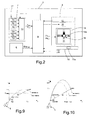
Figure 1 schematically shows a grenade launcher in a target pointing attitude provided with an assisting optoelectronic digital apparatus, made according to the dictates of the present invention; -
Figure 2 is a block diagram of the assisting optoelectronic apparatus shown inFigure 1 ; -
Figure 3 is a schematic view from above and side elevation of the grenade launcher offigure 1 in a shooting attitude; -
Figures 4a ,4b and4c show as a whole a flowchart containing the operations implemented by the assisting optoelectronic digital apparatus shown inFigure 1 ; -
Figures 5, 6 7 and 8 schematically show examples of the graphical cross generated by the assisting optoelectronic apparatus to indicate to the military operator the direction to be given to the grenade launcher to strike the moving target; -
Figures 9 and 10 show two examples of the ideal and actual grenade trajectory in a Cartesian plane of reference, when a respectively "flat" and a "non-flat" shot typology is executed. - With reference to
Figure 1 , withnumber 1 is indicated as a whole a hand-held grenade launcher, to which an assistingoptoelectronic apparatus 2 is coupled being configured so as to assist an operator in determining the shooting attitude to be given to thegrenade launcher 1 itself so as to strike a moving target K. - The assisting
optoelectronic apparatus 2 is also configured so as to communicate to the operator, moment by moment, the angular pitch and heading movements to be given to thegrenade launcher 1 to strike the target k, based on the differences in space present between the determined shooting attitude and the instantaneous attitude given to thegrenade launcher 1 by the operator and the given next motion of the target k. - The
grenade launcher 1 can be preferably, but not necessarily, mounted on a hand-heldweapon 3, for example, a rifle and in the example shown inFigure 1 comprises agrenade launch tube 4 presenting a longitudinal axis L coincident and integral with a first Cartesian axis XBODY of a predetermined body reference system ΣBODY associated with thegrenade launcher 1, and presenting a second Cartesian axis YBODY, orthogonal to the first Cartesian axis XBODY, and a third Cartesian axis ZBODY orthogonal to the first XBODY and to the second Cartesian axis YBODY. - The
grenade launcher 1 also comprises apointing device 5 adapted to enable the operator to aim at the moving target k and then place thegrenade launcher 1 in a pointing attitude on the basis of the display of the target k itself. - The
pointing device 5 is of a known type and therefore will not be further described except to clarify that it can be configured so that, for example, in the pointing attitude, the longitudinal axis L of thegrenade launch tube 4 intersects the target k. - With reference to
Figure 2 , the assistingoptoelectronic apparatus 2 comprises an electronicdistance measuring device 6, which is configured to measure the distance Disttarget of the target K from thegrenade launcher 1; and an electronicattitude measuring device 7, which is configured for determining the instantaneous attitude of thegrenade launcher 1, i.e. the pitch angle Δαpitch and the heading angle Δαhead that characterize the attitude itself. - The assisting
optoelectronic apparatus 2 also comprises auser interface 8 by which an operator is able to issue commands to the assistingoptoelectronic apparatus 2 and receives indications on variation in attitude Δαpitch and Δαhead to be given to thegrenade launcher 1 to strike the moving target k. - The assisting
optoelectronic apparatus 2 also comprises anelectronic processing unit 9, which is configured so as to compute the pitch angle Δαpitch, and the heading angle αfhead that characterize the shooting attitude, and communicates to the operator, by way of theuser interface 8 and, in response to the movement of thegrenade launcher 1 itself by the operator, the variation in attitude Δαpitcht Δαhead to be given to thegrenade launcher 1 to orientate it so as to strike the moving target k. - The assisting
optoelectronic apparatus 2 further comprises amemory unit 10 containing a series of ammunition-data indicating a plurality of different grenade types employable in thegrenade launcher 1. - The
memory unit 10 further contains, for each type of grenade, a series of ballistic data associated with the grenade itself, such as: the frontal area S of the grenade i.e. the area of the front surface of the grenade itself; the mass m of the grenade; the coefficient of aerodynamic resistance Cd of the grenade; the lift coefficient Cl of the grenade; the launching speed of the grenade Vin; a coefficient Vin1 correlated with the launching speed variation Vin of the grenade at changing temperature T. - The
memory unit 10 is also adapted for further storing: environmental data indicating the atmospheric pressure p, the thermodynamic constant of air R; and precision data indicating a minimum desired precision erry of impact of the grenade on the target K along a vertical axis (e.g. the axis Y inFigure 1 ), which is orthogonal to a flat Earth's ground reference surface, and a minimum desired precision errx of impact of the grenade on the target K along a horizontal axis (e.g. the axis X inFigure 1 ) parallel to a flat Earth's ground surface in the shooting direction (errors related to the action range of the grenade in use). - The assisting
optoelectronic apparatus 2 also comprisessensors 11 adapted to measure the air temperature T, corresponding in the initial step, to the temperature of the grenade. - With reference to
Figure 2 , thedistance measuring device 6 may comprise, for example, a LASER rangefinder (acronym for Light Amplification by Stimulated Emission of Radiation), which is configured so as to emit laser pulses towards the target determining the distance Disttarget of the target from thegrenade launcher 1 in function of the "flight time" tflight of the LASER pulse. - Regarding instead the electronic
attitude measuring device 7, in the example shown inFigure 2 it comprises an inertialelectronic platform 12 configured to provide in output the acceleration components Ax, Ay, Az and angular velocity components Gx, Gy and Gz of thegrenade launcher 1 determined with respect to the body reference system ΣBODY. - In particular, in the example shown in
Figure 2 , the inertialelectronic platform 12 conveniently comprises one or more accelerometers (not illustrated), for example, a dual-axis accelerometer and two single-axis accelerometers, presenting two measuring axes arranged along the axes XBODY and YBODY of the body reference system ΣBODY; and one or more gyroscopes presenting a total of three measuring axes arranged parallel to the axes XBODY, YBODY and ZBODY of the body reference system ΣBODY. - The attitude measuring
device 7 also comprises acomputing module 13 receiving the input acceleration components Ax, Ay, Az, and the angular velocity components Gx, Gy and Gz measured by the electronicinertial platform 12 thus processing them to provide in output the pitch angle Δαpitch, and the heading angle Δαhead. - In this case, the pitch Δαpitch and heading Δαhead angles can be conveniently determined by the
computing module 13 by way of, for example, the computing method described in the patent application filed in Italy on April 12, 2010 with the No. TV2010A000060, which is here incorporated as reference. - Regarding the
user interface 8, comprising a screen or display 14 to visualize one or more graphic interfaces, acontrol device 15, and preferably but not necessarily a voicemessage generating device 16. - In particular, the
electronic processing unit 9 can be configured so as to ensure that thedisplay 14 and/or the voicemessage generating device 16 notifies the operator attitude variations Δαpitch and Δαhead to be given to thegrenade launcher 1, while thecontrol device 15 may comprise a keyboard provided with a set of keys through which the operator imparts commands to the assistingoptoelectronic apparatus 2. - In the example shown in
Figure 2 , thedisplay 14 is conveniently of an OLED type (acronym for Organic Light Emitting Diode) while theelectronic processing unit 9 is configured to ensure that also thedisplay 14 visualizes a supportinggraphical interface 14a representing the attitude variation Δαpitch and Δαhead to be given to thegrenade launcher 1 to strike the moving target k. - In detail, the
electronic processing unit 9 is configured to ensure that the assistinggraphical interface 14a visualized by thedisplay 14 comprises agraphical attitude cross 18 provided with a plurality of luminous segments arranged aligned one after the other so as to form a first and a second attitude branch which are mutually orthogonal and intersect a common central point. - More in detail, in the example shown in
Figures 5-8 , theelectronic processing unit 9 is configured to switch on/off: - the segments of a
vertical attitude branch 20 as a function of the positive or negative variation Δαpitch of the pitch angle αpitch to be given to thegrenade launcher 1 so as to orient it in the shooting attitude; - the segments of a
horizontal attitude branch 21 as a function of positive or negative variation of Δαhead the heading angle αhead to be given to thegrenade launcher 1 so as to orient it in the shooting attitude. - More specifically, in the example shown in
Figures 5-8 , theattitude branch 20 is subdivided in correspondence to the midpoint in a first 20a and in a secondluminous branch 20b, wherein the firstluminous branch 20a comprises a predetermined number N1 of segments adapted to be switched on/off in function of the negative variation of the pitch angle Δαpitch, while the secondluminous branch 20b comprises a predetermined number N1 of segments adapted for being switched on/off in function of the negative variation of the pitch angle Δαpitch. - The second
luminous branch 21 is in turn divided in correspondence to the midpoint in a first 21a and in a secondluminous branch 21b, wherein the firstluminous branch 21a comprises a predetermined number N3 of segments adapted for being switched on/off in function of the negative variation of the heading angle Δαhead, while the secondluminous branch 21b comprises a predetermined number N4 of segments adapted for being switched on/off in function of the positive variation of the heading angle Δαhead. - It should be specified that with the following term "shooting attitude" of the
grenade launcher 1 it will be intended the condition in which thegrenade launcher 1 is oriented in space ensuring that the grenade will strike the target K; while with the term "pointing attitude" it will be intended the condition in which the operator points at the target by way of the pointing device 5 (Figure 1 ). - More specifically, with reference to
figure 3 , at a generic moment ti, the general attitude of thegrenade launcher 1 is characterized by a pitch angle ΔαPITCH(ti) and a heading angle αHEAD(ti), wherein the pitch angle αPITCH(ti) corresponds to the angle present between the first Cartesian axis XBODY and a reference plane lying on Earth's ground level; while the heading angle αHEAD(ti) corresponds to the azimuth angle present between the first Cartesian axis YBODY and Earth's geographic NORTH. - As for the voice
message generating device 16 it can be configured so as to communicate voice messages containing the attitude variation Δαhead and Δαpitch to be given to thegrenade launcher 1 to strike the moving target. The voicemessage generating device 16 can comprise, for example, an electronic digital unit configured to produce digital voice messages and a loudspeaker such as a headset connected to the electronic digital unit and usable by the operator for listening to information relative to the attitude variation Δαhead and Δαpitch to be given to thegrenade launcher 1. - Regarding the
electronic processing unit 9, it can comprise a microprocessor receiving in input: pitch Δαpitch and heading Δαhead angles; the distance Disttarget of the target; and commands given by the user by way of thecontrol device 15. - The
electronic processing unit 9 also receives a series of data indicative of the type of grenade to be launched such as: the frontal area S, the mass m, the coefficient of aerodynamic resistance Cd; the lift coefficient C1; the speed of release Vin of the grenade; the coefficient of variation Vin1. - The
electronic processing unit 9 further receives a series of data indicative of the atmospheric pressure p; of the thermodynamic constant of the air R; and data indicative of minimum desired precision impact erry and errx along the X and Y axis respectively. - The
electronic processing unit 9 is adapted to implement a computing method that processes the input variables listed above to communicate to the operator in output, moment by moment, the attitude variation Δαpitch and Δαhead to be given to thegrenade launcher 1 for achieving the correct shooting attitude necessary to strike a moving target k. - More specifically, the
electronic processing unit 9 is adapted to vary the number N1 and/or N2 of switching on/off of the segments contained in the firstluminous branch 20, and the number N3 and/or N4 of switching on/off of the segments contained in the secondluminous branch 21, so as to conveniently visually notify the operator the angle to be given so as to place thegrenade launcher 1 in the shooting attitude. - With reference to
Figures 4a ,4b and4c it will be described below the computing method implemented by theelectronic processing unit 9 to determine the attitude variations Δαpitch and Δαhead to be given to thegrenade launcher 1 to strike the moving target K where it is assumed that the assistingoptoelectronic apparatus 2 is configured/set on the basis of a particular type of grenade. - In particular, the configuration/setting of the assisting
optoelectronic apparatus 2 can provide that: theelectronic processing unit 9 notifies the operator by way of theuser interface 8 the different types of grenades usable contained in thememory unit 10 and determines in thememory unit 10 itself the data that characterize the grenade ballistics, in response to a selection command of the grenade given by the operator. - In the initial step, the operator selects, by way of the
user interface 8, the type of shooting trajectory to be given to the grenade, which may correspond to a first type, later indicated with "flat shot" an example of which is shown inFigure 9 , or a second type, later indicated with "non-flat shot" an example of which is shown inFigure 10 (block 100). - The method essentially provides a series of data acquisition operations, and a series of computing attitude operations to be given to the
grenade launcher 1 to strike the moving target k on the basis of the acquired data. - In particular, the method preferably, but not necessarily, provides that the
electronic processing unit 9 communicates to the operator through the user interface 8 a request of pointing/tracking of the target k by way of the grenade launcher for a given time interval. - The operator orients the
grenade launcher 1 towards the target k so as to position it in the pointing attitude (block 110) (Figure 1 ) and simultaneously imparts by way of the user interface 8 a command to activate data acquisition (t=tC0) (block 120). At this step, the assistingoptoelectronic apparatus 2 samples at each sampling instant tci (i comprised between 0 and n): the distances of the target k from thegrenade launcher 1 Disttarget=(Disttarget(tC0),...,Disttarget(tCn)). the pitch angles αpitch=(αpitch(tC0),..,αpitch(tCn)) and the heading angles αhead=(αhead(tc0),...,αhead(tCn)) that define the attitude of the grenade launcher 1 (block 130) and stores the sampled data in the memory unit 10 (block 140). - To this aim, the
memory unit 10 can be conveniently structured so as to comprise acircular memory buffer 10a (shown inFigure 1 ) in which the sampled data Disttarged(tci αpitch(tci), αhead(tci) acquired during sampling stored. - The
electronic processing unit 9 verifies whether thememory buffer 10 is saturated/full (block 150) and in a negative case (output NO from block 150), increases the sampling moment tci=tci +1 (block 160) and repeats again thesteps - In a positive case (output YES from block 150), i.e. if the
memory buffer 10 is saturated/full, theelectronic processing unit 9 temporally sorts the distance/attitude data Disttarget(tci), αpitch(tci), αhead(tci) contained in the buffer memory 30 (block 170), and processes the same sorted data Disttarget(tci), αpitch(tci), αhead(tci) to determine the positions PI taken by the target k in time with respect to the Cartesian system S (X,Y,Z) (shown inFigure 1 ) whose origin S (0,0,0) is positioned at a predetermined point of thegrenade launcher 1, for example at the muzzle of the grenade launch tube 4 (block 180). - In detail, the
electronic processing unit 9 computes the target position vectors PI=Pi(tci)=(XT(tci),YT(tci),ZT(tci) starting from the initial sampling moment tci=tc0 to to a final sampling moment tci=tcn:


- The
electronic processing unit 9 computes on the basis of vectors IP containing the coordinates of the positions taken by the target k in time, and by way of an optimization method, e.g. such as the method of least squares or any other similar motion approximation method of the polynomial functions, preferably but not necessarily, of first degree, which allow to establish with a certain degree of approximation, the actual positions Pi(tc0),Pi(tcn) and next positions Pi(tcn+1) P(tcn+k) taken by the target k during its movement (block 190). - In particular, in this step the method implements the following relations that allow to determine, by way of the polynomial functions F(X), F(y), F(Z) preferably but not necessarily of first degree, the movement of the target in space:
- a)


- At this point, the
electronic processing unit 9 computes the ideal grenade motion (block 200), implementing an algorithm that determines, starting from an assistance request moment tact, the solution to the problem of the ideal grenade motion subject to gravitational force, by way of the determination of range GIT, of the output speed VIN from thegrenade launcher 1, the ideal pitch angle αidealpitch and of the flight time tflight used by the grenade to strike the target k. - It should be made clear that the assistance request moment tact can correspond to the moment when the operator by way of the
graphical interface 8 gives a command signal requesting the computation of shooting attitude. - In particular, the
electronic processor 1 computes: - b)

- The
electronic processing unit 9 initializes a counter Inum=0 (block 210) and computes (block 220) the impact moment timp of the grenade on the target k by way of the following relation: - c)

- The
electronic processing unit 9 computes by way of the polynomial functions F(X), F(y), F(Z) the target position XT(timp),YT(timp),ZT(timp) at impact moment timp, and determines the distance Disttarget of the target k with respect to thegrenade launcher 1 at impact moment timp itself by way of the following relation: - d)

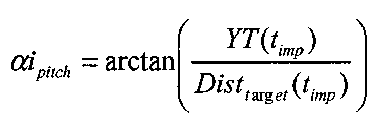
- The
electronic processing unit 9 determines (block 230) a pitch angle αipitch corresponding to the angle to be given to thegrenade launcher 1 to strike the target k under ideal conditions, by way of the following relation: - e)
- At this point, the
electronic processing unit 9 determines whether: - f) the impact distance of Disttarget is comprised within a predetermined distance range delimited by a minimum dTMIN and a maximum dTMAX value;
- g) the pitch angle αipitch is comprised within a predetermined angular range delimited by a minimum α1 and a maximum α2 value, in which α1 conveniently has a value of about -0.78 and α2 conveniently is equal to approximately 0.78 (block 240).
- In the event in which at least one of the conditions f) and g) is not satisfied (output NO from block 240), the assisting
optoelectronic apparatus 2 generates a message that alerts the operator of a condition of non possibility to compute the shooting angle and requests execution of a new pointing of the target and a new data acquisition (blocks 110-230). - However, if the conditions f) and g) are both satisfied (output YES from block 240), the
electronic processing unit 9 initializes an integrating counter i=1 (block 250) to determine the actual trajectory of the grenade on the basis of the ideal trajectory, of the ballistic data, of the environmental data and of the accuracy data. - In particular, the
electronic processing unit 9 computes a real infinitesimal displacement Δxi and Δyi of the grenade with respect to the axes X and Y, in a moment of time t=tact+i*dt, where dt is a predetermined integrating interval by way of the following relations h) and i) (block 260): - h)

- i)

- At this point, the
electronic processing unit 9 increases the integrating counter i=i+1 and computes the slope of the actual trajectory of the grenade at moment ti=tact+i*dt by way of the following relation) (block 270) : - l)

- The
electronic processing unit 9 further computes the speed of the grenade Viprojectile at moment ti by way of the following relation f) (block 280): - m)

- The
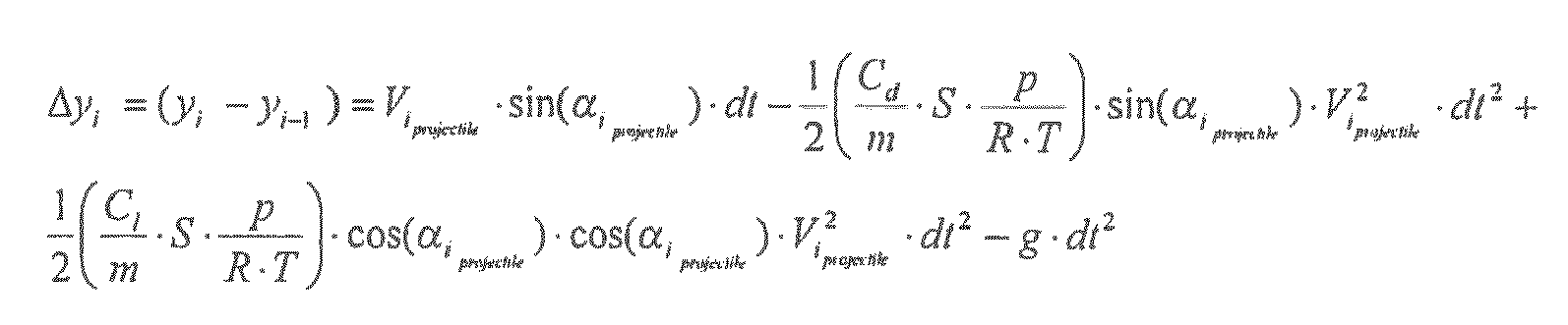
electronic processing unit 9 increases again the integrating counter i=i+1 (block 290) and computes the subsequent real infinitesimal displacements Δxi Δyi afflicting the grenade in moments of time ti=tact+i*dt. - In this case, the calculation of each infinitesimal displacement Δxi and Δyi of the grenade along the actual trajectory made in each time interval dt is calculated by way of the following relation n) and o) (block 300):
- n)

- o)

- With reference to
Figure 4c , following the computation of the infinitesimal displacement, theelectronic processing unit 9 determines the new trajectory slope, the new speed of the grenade, and so on until determining the whole actual trajectory corresponding to the ideal start angle αipitch. - In particular, for each integration step of the trajectory, the
electronic processing unit 9 verifies whether a first or second condition is satisfied in which: - p) the first condition is satisfied when X1=ΔXi+Xi-1>=XT(timp) and the selected shot is flat;
- q) the second condition is satisfied when: Yi=ΔYi+Yi-1 <=YT(timp), variation Δyi of the grenade is negative and the selected shot is non-flat (block 310).
- If the first p) and the second q) condition are not satisfied (output no from block 310), the
electronic processing unit 9 executes again the described steps inblocks - However, if one or both conditions p) or q) are satisfied (output yes from block 310), then the
electronic processing unit 9 verifies (block 320) if the third and fourth conditions are satisfied in which: - r) the third condition is satisfied when the displacement Xi of the grenade is in the range delimited by a minimum value XT(timp)timp)-errx and a maximum value XT(timp)+errx; while
- s) the fourth condition is satisfied when the displacement Yi of the grenade is in the range delimited by a minimum value YT(timp)-erry and a maximum value YT(timp)+erry (block 320).
- If the third r) and fourth s) condition is satisfied (output yes from block 320), the
electronic processing unit 9 gives to the pitch shooting angle the value of the pitch angle given from the method in the initial step (i.e. in the block 270) of the computing cycle αipitch:
- If at least one of r) or s) conditions is not met (output no from block 320) then the
electronic processing unit 9 starts computing a new trajectory (block 340), in which the starting angle αipitch varies by way of the relation s) in case of "flat" shot, or by way of the relation t) in case of "non flat" shot: s)
- t)

- In this case, the
electronic processing unit 9 implements again the above described steps provided in the blocks 260-340. - Following the computation of the shooting pitch angle αfpitch=αipitch, the
electronic processing unit 9 computes the shooting heading angle αfhead by way of the following mathematical relation u):
- At this point the
electronic processing unit 9 increases the counter Inum=Inum+1 (block 360) and verifies (block 370) if: - u) Inum>=ITMAX; where ITMAX is a predetermined threshold indicating a maximum number of interactions that can be made during a predetermined computing interval Δt;
- v)

- In the event that either condition u) or v) is not satisfied (output no from block 370), the
electronic processing unit 9 provides to re-implement the block operations 220-370. - With reference to
Figure 4d , whereas if the two conditions u) or v) are satisfied (output yes from block 370), theelectronic processing unit 9 confirms the assignment to the shooting pitch angle, and assigns the shooting heading angle αfhead=αfhead(Inum), preferably but not necessarily to a parameter ISP indicating the moment of explosion of the grenade, the impact moment timp; to the target distance Disttarget the value range of the range GIT(timp) and to a counting parameter of the number of cycles NUMCI the counter value Inum (block 380). - At moment tact, the
electronic processing unit 9 determines the effective pitch angle αpitch(tact) and verifies if the following first condition a1) is satisfied (block 400): - a1)

- In a positive case, i.e. if the condition a1) is satisfied (output YES from block 400), the
electronic processing unit 9 determines that the pitch angle αpitch(tact) corresponds to the final pitch angle αfpitch, i.e. that thegrenade launcher 1 has a correct pitch attitude (block 410) and therefore does not require movements of thegrenade launcher 1 adapted to vary the pitch angle αpitch(tact) itself. - The
electronic processing unit 9 commands, by way of theuser interface 8, the maintaining of segments N1 and N2 in the off condition so as to communicate to the operator the absence of rotations i.e. variations of the pitch angle to be given to the grenade launcher 1 (block 410) (Figure 8 ). - In a negative case (output NO from block 400), i.e. if the condition a1) is not satisfied, the
electronic processing unit 9 determines the integer to be assigned to the unknown value npitch to satisfy the condition a2) : - a2)

- At this point if npitch has a positive value, the
electronic processing unit 9 controls the switching on of a number N1' = npitch of the luminous segments of thegraphical attitude cross 18 by way of the user interface 8 (Figures 5,7 ), while if npitch has a negative value, theelectronic processing unit 9 controls the switching on of a number N2' =npitch of the luminous segments of thegraphical attitude cross 14 by way of the user interface 8 (block 430) (Figure 6 ). - At moment tact, the
electronic processing unit 9 also determines the heading angle αhead(tact) and verifies if the following condition b1) is satisfied (block 450): - b1)

- In a positive case (output yes from block 450), i.e. if the condition b1) is satisfied, the
electronic processing unit 9 determines that the heading angle αhead(tact) corresponds to the final heading angle αfhead, i.e. that thegrenade launcher 1 has a correct heading attitude (block 460) and therefore does not require movements of thegrenade launcher 1 adapted to vary the heading angle αhead itself. - The
electronic processing unit 9 commands, through theuser interface 8, the maintaining of segments N3 and N4 in a switching off position so as to communicate to the operator the absence of rotations αhead to be given to the grenade launcher 1 (Figure 5 and 8 ). - In a negative case, i.e. if the condition b1) is not satisfied, the
electronic processing unit 9 determines the integer to be assigned to the unknown value nhead to satisfy the following condition b2): - b2) Δαhead=nhead*Sa (block 470)
- At this point if nhead has a positive value, the
electronic processing unit 9 controls the switching on of a number N3'= nhead of the luminous segments of the graphical attitude cross 18 (Figure 7 ), while if nhead has a negative value, theelectronic processing unit 9 controls the switching on of a number N4'=nhead of the luminous segments of the graphical attitude cross 18 (block 480) (Figure 6 ). - In the case in which the relations a1) and b1) are satisfied the
electronic processing unit 9 communicates to the operator the correct positioning of thegrenade launcher 1 in the shooting attitude (block 500). In this case, in the example shown infigure 8 , theelectronic processing unit 9 controls the switching off of all segments and preferably, but not necessarily, the switching on of a central graphical icon comprising for example a circle centered on the center. - At this point the
electronic processing unit 9 verifies if the computing interval Δt from the moment in which the operation has been carried out in block 210 (block 510) has passed and in a negative case (output no from block 510) remains in a waiting condition, while in a positive case (output yes from block 510) updates the actual moment tact by giving it the current moment, measured for example by way of an internal clock (block 520), and executes again the operation implemented in theblock 200 and the subsequent operations. - From the above described it should be noted that the above described operations shown in
Figures 4a-4d can be encoded in a software program stored in thememory unit 10 and configured so that when it is loaded onto theelectronic processing unit 9 the latter executes the same operations thereof so as to assist the operator in moving the grenade launcher. - The above described assisting optoelectronic apparatus is extremely advantageous because it automatically provides to the military operator a precise indication of the orientation to be given to the grenade launcher in such a way so as to successfully strike a moving target.
- Finally, it is clear that changes and variations to the electronic apparatus and to the functioning method may be applied without extending beyond the scope of the present invention defined by the appended claims.
αidealpitch=(1/2) arcsin (GIT*g/VIN 2)
tflight=2*(VIN/g) sin (αidealpitch)
wherein XT(tact), YT(tact) and ZT(tact) are the coordinates of the position PI of the grenade at the assistance request moment tact.
Claims (15)
- An optoelectronic digital apparatus (2) for assisting an operator in determining the shooting attitude to be given to a hand-held grenade launcher (1) so as to strike a moving target (k), through a grenade; said apparatus (2) comprising:o measuring electronic means (6)(7) configured so as to measure the pitch angle (αpitch) and the heading angle (αhead) indicative of the attitude of the grenade launcher (1), and the distance (Disttarget) of the target (k) from the hand-held grenade launcher (1);o user interface means (8) configured so as to receive an operator-assistance request at a first operative time (tact), and communicate indications on the attitude to be given to the grenade launcher to cause the grenade launcher (1) to strike a moving target (k);o memory means (10) containing ammunition-data (S, m, Cd, C1, VIN, VIN1 indicative of the ballistic behaviour of said grenade; environmental-data indicative of the environmental parameters (p, R); and precision-data (errx, erry) indicative of the required impact precision; ando processing electronic means (9) configured so as to:wherein the step of determining the shooting attitude comprises the following steps:measure, through said measuring electronic means (7), a plurality of pitch angles (αpitch (tci) and heading angles (αhead(tci)) taken in a sequence from the grenade launcher (1) in a predetermined data sampling range, during which the operator moves the grenade launcher (1) to maintain it pointed towards the moving target (k);measure, through said measuring electronic means (6), a plurality of distances Disttarget(tci) taken in a sequence by the target (k) from the grenade launcher (1) during said data sampling range;determine a displacement mathematical function (F(X),F(y),F(Z)) associated to the motion of the target (k), on the basis of the pitch angles (αpuch(tci)) of the heading angles (αheading(tci)) and of the distances (Disttarget(tci)) measured during said data sampling range;determine an ideal pitch angle (αidealpitch) and a theoretical impact time (timp) of the grenade on the target (k), through said displacement mathematical function and on the basis of the ammunition-data so that the grenade strikes the target (k) at the position of the target (k) at said first operative time (tact);determine, on the basis of said ideal pitch angle (αidealpitch), ammunition-data, environmental-data and precision-data, a shooting attitude comprising a shooting pitch angle (αfpitch) and a shooting heading angle (αfhead) to be given to the grenade launcher (1) so that the grenade strikes the target (k) at said theoretical impacttime (timp);measure, through said measuring electronic means (7), the actual pitch angle (αpirch(tact)) and the actual heading angle (αheading(tact)) indicating the attitude given by the operator to the grenade launcher (1) at said first operative time (tact);compute a pitch difference (Δαpitch(tact)) between the shooting pitch angle (αfpitch) and the actual pitch angle (αpitch(tact)) measured at said first operative time (tact);compute a heading difference (Δαpitch(tact)) between the shooting heading pitch (αfhead) and the heading angle (αhead(tact)) measured at said first operative time (tact);communicate, through said user interface (8), data indicative of the variation of the pitch angle and/or of the heading angle which the operator must give to the grenade launcher (1) so that the pitch difference (Δαpitch(tact)) and the heading difference (Δαhead(tact)) measured at said first operative time (tact) is zero;- determine an initial pitch angle (αipitch) through said displacement mathematical function (F(X,F(y),F(Z)) on the basis of said ammunition-data and of said theoretical impact time (timp);- compute a trajectory of said grenade on the basis of said initial pitch angle (αipitch) and of said ammunition-data and of said environmental-data;- vary said initial pitch angle (αipitch) until the corresponding trajectory of the grenade satisfies a convergence condition towards said target (k);- assign, to said shooting pitch angle (αfpitch), the pitch angle (αipitch) corresponding to the trajectory of the grenade that satisfies said convergence condition.
- The apparatus according to claim 1, wherein said processing electronic means (9) are configured so as to:- receive, through said interface means (8), a selection control of a flat-trajectory shot type or of a non-flat-trajectory shot type;- in case a flat-trajectory shot is selected, vary said initial pitch angle (αipitch) through the following relation:
 - in case a non-flat-trajectory shot is selected, vary said initial pitch angle (αipitch) through the following relation:wherein XT(timp) and YT(timp) are the coordinates of the position of the target (k) at said theoretical impact time (timp); xi and yi are the coordinates of the position taken by the grenade along the trajectory at a time i, determined with respect to a reference Cartesian system (S(X,Y,Z)); and max(yi) is the maximum value of the coordinate of the trajectory of the grenade along a first axis (Y) of the reference Cartesian system (S(X,Y,Z)).
- The apparatus according to claim 2, wherein said processing electronic means (9) are configured so as to compute said shooting heading angle (αfhead) through the following relation:

- The apparatus according to claim 3, wherein said processing electronic means (9) are configured so as to:- compute a first infinitesimal displacement (xi, yi) associated to the trajectory of said grenade along said first (Y) and second axis (X) on the basis of said initial pitch angle (αipitch) and of said ballistic data and of said environmental-data, through the relations:

 - compute a first angle of inclination of the grenade through the relation:
 - compute a shooting speed of the grenade through the relation:
 - sequentially compute infinitesimal displacements (xi, yi) associated to the trajectory of said grenade along said first (Y) and second axis (X) on the basis of said initial pitch angle (αipitch) of said ballistic data and of said environmental-data, in which each computation implements said relations:

- The apparatus according to claim 4, wherein said processing electronic means (9) are configured so as to determine the convergence condition of said trajectory towards the target (j) when a first or a second condition is satisfied- said first condition occurring if:Xi=ΔXi+Xi-1>=XT (timp) and the selected shot type is a flat-trajectory shot;- said first condition occurring if:Yi=ΔYi+Yi-1 <=YT(timp), the variation Δyi of the grenade is negative; and the selected shot type is a non-flat-trajectory shot.
- The apparatus according to claim 5, wherein said processing electronic means (9) are configured so as to vary said initial pitch angle (αipitch) when a third or a fourth condition are not satisfied; in which- the third condition is satisfied if the position Xi of the grenade is comprised in the range defined by a minimum value XT (timp)-errx and a maximum value corresponding to XT (timp) +errx in which errx is a value of said precision-data that indicates the precision required along said second axis (X); while- the fourth condition is satisfied if the value Yi of the grenade is comprised in the range defined by a minimum value YT(timp)-erry and a maximum value corresponding to YT(timp)+erry in which erry is a value of said precision-data that indicates the precision required along said first axis (Y).
- The apparatus according to claim 6, wherein said interface means (8) comprise a display (14) displaying a graphical attitude cross (18) provided with a plurality of luminous segments arranged aligned one after the other so as to form a first (20) and a second attitude branch (21);
said processing electronic means (9) being configured to switch on/off:- the segments of a first attitude branch (20) as a function of the variation of the pitch angle (Δαpitch) to be given to the grenade launcher (1) so as to orient it in the shooting attitude; and/or- the segments of a second attitude branch (21) orthogonal to the first attitude branch (20), as a function of the variation of the heading angle (Δαhead) to be given to the grenade launcher (1) so as to orient it in the shooting attitude. - A method for assisting an operator through an optoelectronic digital apparatus (2) in determining the shooting attitude of a hand-held grenade launcher (1) so as to strike a moving target (k) through the grenade, wherein said digital apparatus (2) comprises measuring electronic means (6) (7) configured so as to measure the pitch angle (αpitch) and the heading angle (αhead) indicative of the attitude of the grenade launcher (1), and the distance (Disttarget) of the target (k) from the hand-held grenade launcher (1); user interface means (8) configured so as to receive an operator-assistance request at a first operative time (tact), and communicate indications on the attitude to be given to the grenade launcher (1) so as to strike the moving target (k); memory means containing ammunition-data (S, m, Cd, C1,VIN,VIN1) indicative of the ballistic behaviour of said grenade; environmental-data indicative of the environmental parameters (p,R); and precision-data (errx,erry) indicative of the required impact precision;
said method comprising the steps of:o measuring, through said measuring electronic means (7), a plurality of pitch angles (αpitch(tci) and heading angles (αhead(tci)) taken in a sequence by the grenade launcher (1) in a predetermined data sampling range, during which the operator moves the grenade launcher (1) to maintain it pointed towards the moving target (k);o measuring, through said measuring electronic means (6), a plurality of distances Disttarget(tci) taken in a sequence by the target (k) from the grenade launcher (1) during said data sampling range;o determining a displacement mathematical function (F(X),F(y),F(Z)) associated to the motion of said target, on the basis of the pitch angles (αpitch(tci)), of the heading angles (αheading(tci)) and of the distances (Disttarget(tci) measured during said data sampling range;o determining an ideal pitch angle (αidealpitch) and a theoretical impact time (timp) of the grenade on the target (k), through said displacement mathematical function and on the basis of the ammunition-data so that the grenade strikes the target (k) at the position of the target (k) at said first operative time (tact);o determining, on the basis of said ideal pitch angle (αidealpitch) and of the ammunition-data, a shooting attitude comprising a shooting pitch angle (αfpitch) and a shooting heading angle (αfhead) to be given to the grenade launcher (1) so that the grenade strikes the target (k) at said theoretical impact time (timp);o measuring, through said measuring electronic means (7), the actual pitch angle (αpitch(tact)) and the actual heading angle (αheading(tact)) indicating the attitude given by the operator to the grenade launcher (1) at said first operative time (tact);o computing a pitch difference (Δαpitch (tact)) between the shooting pitch angle (αfpitch) and the actual pitch angle (αpitch(tact)) measured at said first operative time (tact);o computing a heading difference (Δαhead(tact)) between the shooting heading angle (αfhead) and the heading angle (αhead(tact)) measured at said first operative time (tact);o communicating, through said user interface (8), data indicative of the variation of the pitch angle and/or of the heading angle which the operator must give to the grenade launcher (1) so that the pitch difference (Δαpitch(tact)) and the heading difference (Δαhead(tact)) measured at said first operative time (tact) is zero.wherein the step of determining the shooting attitude comprises the following steps:- determining an initial pitch angle (αipitch) through said displacement mathematical function (F(X),F(y),F(Z)) on the basis of said ammunition-data and of said theoretical impact time (timp);- computing a trajectory of said grenade on the basis of said initial pitch angle (αipitch) and of said ammunition-data and of said environmental-data;- varying said initial pitch angle (αipitch) until the corresponding trajectory of the grenade satisfies a convergence condition towards said target (k);- assigning the pitch angle (αipitch) corresponding to the trajectory of the grenade that satisfies said convergence condition to said shooting pitch angle (αfpitch). - The method according to claim 8, comprising the steps of:- receiving, through said interface means (8), a selection control of a flat-trajectory shot type or of a non-flat-trajectory shot type;- in case a flat-trajectory shot is selected, varying said initial pitch angle (αipitch) through the following relation:
 - in case a non-flat-trajectory shot is selected, varying said initial pitch angle (αipitch) through the following relation:wherein XT(timp) and YT(timp) are the coordinates of the position of the target (k) at said theoretical impact time (timp); xi and yi are the coordinates of the position taken by the grenade along the trajectory at a time i, determined with respect to a reference Cartesian system (S(X,Y,Z)); and max(yi) is the maximum value of the coordinate of the trajectory of the grenade along a first axis (Y) of the reference Cartesian system (S(X,Y,Z)).
- The method according to claim 9, comprising the steps of computing said shooting heading angle (αfhead) through the following relation:

- The method according to claim 10, comprising the steps of:- computing a first infinitesimal displacement (xi, yi) associated to the trajectory of said grenade along said first (Y) and second axis (X) on the basis of said initial pitch angle (αipitch) and of said ballistic data and of said environmental-data, through the relations:

 - computing a first angle of inclination of the grenade through the relation:
 - computing a shooting speed of the grenade through the relation:
 - sequentially computing infinitesimal displacements (xi, yi) associated to the trajectory of said grenade along said first (Y) and second axis (X) on the basis of said initial pitch angle (αipicch), of said ballistic data and of said environmental-data, in which each computation implements said relations:
- The method according to claim 8, comprising the steps of:- determining the convergence condition of said trajectory towards the target (j) when a first or a second condition is satisfied- said first condition occurring if:Xi=ΔXi+Xi-1>=XT (timp) and the selected shot type is a flat-trajectory shot;- said second condition occurring if:Yi=ΔYi+Yi-1 <=YT(timp), the variation Δyi of the grenade is negative; and the selected shot type is a non-flat-trajectory shot.
- The method according to claim 8, comprising the steps of:- varying said initial pitch angle (αipitch) when a third or fourth condition are not satisfied; wherein- the third condition is satisfied if the position Xi of the grenade is comprised in the range defined by a minimum value XT(timp)-errx and a maximum value corresponding to XT(timp)+errx in which errx is a value of said precision-data that indicates the precision required along said second axis (X); while- the fourth condition is satisfied if the position Yi of the grenade is comprised in the range defined by a minimum value YT(timp)-erry and a maximum value corresponding to YT(timp)+erry in which erry is a value of said precision-data that indicates the precision required along said first axis (Y).
- The method according to claim 13, wherein said interface means (8) comprise a display (14) adapted to display a graphical attitude cross (18) provided with a plurality of luminous segments arranged aligned one after the other so as to form a first (20) and a second attitude branch (21);
said method comprising the steps of switching on/off:- the segments of a first attitude branch (20) as a function of the variation of the pitch angle (Δαpitch) to be given to the grenade launcher (1) so as to orient it in the shooting attitude; and/or- the segments of a second attitude branch (21) orthogonal to the first attitude branch (20), as a function of the variation of the heading angle (Δαhead) to be given to the grenade launcher (1) so as to orient it in the shooting attitude. - A computer product loadable on a memory of an electronic processing unit designed to implement, when run by the electronic processing unit, the method according to any of claims 8 to 14, so as to assist an operator in determining the shooting attitude to be given to a hand-held grenade launcher (1) to strike a moving target (k).
Priority Applications (1)
| Application Number | Priority Date | Filing Date | Title |
|---|---|---|---|
| PL11768075T PL2593744T3 (en) | 2010-07-12 | 2011-07-12 | Optoelectronic digital apparatus for assisting an operator in determining the shooting attitude to be given to a hand-held grenade launcher so as to strike a moving target, and respective operation method |
Applications Claiming Priority (2)
| Application Number | Priority Date | Filing Date | Title |
|---|---|---|---|
| ITTV2010A000100A IT1401016B1 (en) | 2010-07-12 | 2010-07-12 | OPTOELECTRONIC DIGITAL APPARATUS TO ASSIST A OPERATOR IN DETERMINING THE SHOE STRUCTURE TO BE ATTACHED TO A PORTABLE GRENADE LAUNCHER TO HIT A TARGET IN MOVEMENT, AND ITS FUNCTIONING METHOD. |
| PCT/IB2011/001620 WO2012007820A1 (en) | 2010-07-12 | 2011-07-12 | Optoelectronic digital apparatus for assisting an operator in determining the shooting attitude to be given to a hand-held grenade launcher so as to strike a moving target, and respective operation method |
Publications (2)
| Publication Number | Publication Date |
|---|---|
| EP2593744A1 EP2593744A1 (en) | 2013-05-22 |
| EP2593744B1 true EP2593744B1 (en) | 2014-12-03 |
Family
ID=43446441
Family Applications (1)
| Application Number | Title | Priority Date | Filing Date |
|---|---|---|---|
| EP11768075.1A Active EP2593744B1 (en) | 2010-07-12 | 2011-07-12 | Optoelectronic digital apparatus for assisting an operator in determining the shooting attitude to be given to a hand-held grenade launcher so as to strike a moving target, and respective operation method |
Country Status (7)
| Country | Link |
|---|---|
| US (1) | US8757487B2 (en) |
| EP (1) | EP2593744B1 (en) |
| BR (1) | BR112013000884A2 (en) |
| EA (1) | EA024098B1 (en) |
| IT (1) | IT1401016B1 (en) |
| PL (1) | PL2593744T3 (en) |
| WO (1) | WO2012007820A1 (en) |
Families Citing this family (17)
| Publication number | Priority date | Publication date | Assignee | Title |
|---|---|---|---|---|
| DE102011105303A1 (en) | 2011-06-22 | 2012-12-27 | Diehl Bgt Defence Gmbh & Co. Kg | fire control |
| EP2776787B1 (en) | 2011-11-08 | 2019-04-03 | Saab Ab | Route planning system and method for minimizing exposure to threats |
| US9163949B2 (en) * | 2011-11-08 | 2015-10-20 | Saab Ab | Dynamic route planning |
| RU2513629C1 (en) * | 2012-10-08 | 2014-04-20 | Николай Евгеньевич Староверов | System of grenade launcher control /versions/ |
| DE102013007229A1 (en) * | 2013-04-26 | 2014-10-30 | Rheinmetall Waffe Munition Gmbh | Method for operating a weapon system |
| DE102013019281A1 (en) | 2013-11-19 | 2015-05-21 | Rheinmetall Soldier Electronics Gmbh | Reflex sight with virtual sight |
| EP2950034A1 (en) * | 2014-05-30 | 2015-12-02 | Patents Factory Ltd. Sp. z o.o. | A method and an apparatus for target aiming |
| US10415933B1 (en) * | 2015-01-20 | 2019-09-17 | Leupold & Stevens, Inc. | Real-time ballistic solutions for moving-target aiming calculations |
| US10502527B2 (en) | 2015-01-20 | 2019-12-10 | Leupold & Stevens, Inc. | Real-time ballistic solutions for calculating an aiming adjustment and for indicating a subsonic threshold |
| US9826359B2 (en) | 2015-05-01 | 2017-11-21 | The Nielsen Company (Us), Llc | Methods and apparatus to associate geographic locations with user devices |
| US9746286B2 (en) | 2015-06-09 | 2017-08-29 | William J. Piepmeyer | System and method for target engagement |
| US10522061B2 (en) * | 2017-03-22 | 2019-12-31 | Solera Holdings, Inc. | Vehicle smart mirror system with heads-up display |
| CN110595441B (en) * | 2018-06-13 | 2021-10-12 | 杭州海康微影传感科技有限公司 | Aiming device |
| CN108874063A (en) * | 2018-06-15 | 2018-11-23 | 郑州艾莫弗信息技术有限公司 | A kind of computer research and development computer cabinet with dedusting function |
| IL280020B (en) | 2021-01-07 | 2022-02-01 | Israel Weapon Ind I W I Ltd | Grenade launcher aiming comtrol system |
| CN114216363B (en) * | 2021-12-13 | 2024-09-10 | 北京一兵科技有限公司 | Auxiliary shooting device and method |
| US12560407B2 (en) * | 2023-09-01 | 2026-02-24 | Bae Systems Information And Electronic Systems Integration Inc. | Target lead estimation based on launcher slew |
Family Cites Families (9)
| Publication number | Priority date | Publication date | Assignee | Title |
|---|---|---|---|---|
| FR2344807A1 (en) * | 1976-03-17 | 1977-10-14 | Realisa Electroniques Et | Antitank rocket firing tube sight - employs laser and calculator on same axes of rotation as tube |
| FR2459443A1 (en) * | 1979-06-15 | 1981-01-09 | Thomson Brandt | Aiming procedure for projectile - includes successive checking of bearing and elevation until they fall within accepted limits |
| DE3837922A1 (en) * | 1988-11-09 | 1990-05-10 | Rheinmetall Gmbh | Method and device for aiming at moving targets, and use of the device for a Panzerfaust (standard German infantry anti-tank weapon) |
| FR2722280B1 (en) * | 1994-07-05 | 1996-08-14 | Thomson Csf | PRECISION SHOOTING AID FOR AN INDIVIDUAL WEAPON |
| US5824942A (en) * | 1996-01-22 | 1998-10-20 | Raytheon Company | Method and device for fire control of a high apogee trajectory weapon |
| US7966763B1 (en) * | 2008-05-22 | 2011-06-28 | The United States Of America As Represented By The Secretary Of The Navy | Targeting system for a projectile launcher |
| US8152065B2 (en) * | 2009-05-05 | 2012-04-10 | Drs Sustainment Systems, Inc. | Hand controller for controlling a long-range sensing system of a weapons system |
| US8157169B2 (en) * | 2009-11-02 | 2012-04-17 | Raytheon Company | Projectile targeting system |
| IT1399418B1 (en) | 2010-04-12 | 2013-04-16 | Selex Galileo Spa | ELECTRONIC APPLIANCE TO DETERMINE THE STRUCTURE OF A WEAPON AND ITS FUNCTIONING METHOD. |
-
2010
- 2010-07-12 IT ITTV2010A000100A patent/IT1401016B1/en active
-
2011
- 2011-07-12 EA EA201390093A patent/EA024098B1/en not_active IP Right Cessation
- 2011-07-12 BR BR112013000884A patent/BR112013000884A2/en not_active Application Discontinuation
- 2011-07-12 EP EP11768075.1A patent/EP2593744B1/en active Active
- 2011-07-12 WO PCT/IB2011/001620 patent/WO2012007820A1/en not_active Ceased
- 2011-07-12 PL PL11768075T patent/PL2593744T3/en unknown
- 2011-07-12 US US13/810,160 patent/US8757487B2/en active Active
Also Published As
| Publication number | Publication date |
|---|---|
| EA201390093A1 (en) | 2013-06-28 |
| ITTV20100100A1 (en) | 2012-01-13 |
| IT1401016B1 (en) | 2013-07-05 |
| EA024098B1 (en) | 2016-08-31 |
| US8757487B2 (en) | 2014-06-24 |
| PL2593744T3 (en) | 2015-06-30 |
| EP2593744A1 (en) | 2013-05-22 |
| WO2012007820A1 (en) | 2012-01-19 |
| WO2012007820A8 (en) | 2012-11-01 |
| BR112013000884A2 (en) | 2016-05-17 |
| US20130181047A1 (en) | 2013-07-18 |
Similar Documents
| Publication | Publication Date | Title |
|---|---|---|
| US8757487B2 (en) | Optoelectronic digital apparatus for assisting an operator in determining the shooting attitude to be given to a hand-held grenade launcher so as to strike a moving target, and respective operation method | |
| US11680774B2 (en) | Methods and systems for training and safety for firearm use | |
| KR102140097B1 (en) | Method of fire control for gun-based anti-aircraft defence | |
| US8563910B2 (en) | Systems and methods for targeting a projectile payload | |
| RU2663764C1 (en) | Method of firing guided missile and system of precision-guided weapons that implements it | |
| KR20130087307A (en) | Trajectory correction method for artillery projectiles | |
| US20230140441A1 (en) | Target acquisition system for an indirect-fire weapon | |
| CN114502465B (en) | Attitude Determination via Pulse Beacons and Low-Cost Inertial Measurement Units | |
| KR102924735B1 (en) | Method, computer program and weapon system for calculating the rupture point of a projectile | |
| US10082366B2 (en) | Fire-control device for a small arm and small arm | |
| US9157702B2 (en) | Munition guidance system and method of assembling the same | |
| WO2012007825A1 (en) | Optoelectronic apparatus for assisting an operator in determining the shooting attitude to be given to a hand-held grenade launcher so as to strike a target, and respective operation method | |
| RU2666378C1 (en) | Method of remote detonation of projectile | |
| KR101560295B1 (en) | Apparatus for simulation target training | |
| US12000674B1 (en) | Handheld integrated targeting system (HITS) | |
| RU2555643C1 (en) | Method of automatic armaments homing at moving target | |
| RU2674401C2 (en) | Method of firing guided artillery projectile | |
| RU2618811C1 (en) | Method for determining conditions of possible unmanned aircraft launch | |
| KR102318621B1 (en) | Attitude control method and attitude control system for wehicle mounted remote control weapon system | |
| RU2676301C1 (en) | Method of shooting with anti-aircraft projectile | |
| RU2674037C1 (en) | Method of surface-to-air projectiles firing to air targets | |
| CN119554931B (en) | Cooperative method, system and storage medium of sequential high-dynamic aircraft | |
| SE544180C2 (en) | Method for controlling target objects | |
| KR102312653B1 (en) | Guided weapon system using weather data and operation method of the same | |
| Zhao et al. | Intelligent simulated electromagnetic gun system based on STM32 |
Legal Events
| Date | Code | Title | Description |
|---|---|---|---|
| PUAI | Public reference made under article 153(3) epc to a published international application that has entered the european phase |
Free format text: ORIGINAL CODE: 0009012 |
|
| 17P | Request for examination filed |
Effective date: 20130117 |
|
| AK | Designated contracting states |
Kind code of ref document: A1 Designated state(s): AL AT BE BG CH CY CZ DE DK EE ES FI FR GB GR HR HU IE IS IT LI LT LU LV MC MK MT NL NO PL PT RO RS SE SI SK SM TR |
|
| DAX | Request for extension of the european patent (deleted) | ||
| 17Q | First examination report despatched |
Effective date: 20131106 |
|
| REG | Reference to a national code |
Ref country code: DE Ref legal event code: R079 Ref document number: 602011011981 Country of ref document: DE Free format text: PREVIOUS MAIN CLASS: F41G0003060000 Ipc: F41G0003160000 |
|
| GRAP | Despatch of communication of intention to grant a patent |
Free format text: ORIGINAL CODE: EPIDOSNIGR1 |
|
| RIC1 | Information provided on ipc code assigned before grant |
Ipc: F41G 3/16 20060101AFI20140612BHEP Ipc: F41G 1/48 20060101ALI20140612BHEP Ipc: F41G 3/06 20060101ALI20140612BHEP Ipc: F41G 1/44 20060101ALI20140612BHEP Ipc: F41G 1/473 20060101ALI20140612BHEP |
|
| INTG | Intention to grant announced |
Effective date: 20140624 |
|
| GRAS | Grant fee paid |
Free format text: ORIGINAL CODE: EPIDOSNIGR3 |
|
| GRAA | (expected) grant |
Free format text: ORIGINAL CODE: 0009210 |
|
| RAP1 | Party data changed (applicant data changed or rights of an application transferred) |
Owner name: SELEX ES S.P.A. |
|
| RIN1 | Information on inventor provided before grant (corrected) |
Inventor name: FOSSATI, ENRICO Inventor name: MAGI, ANDREA Inventor name: SANTINI, NICOLA |
|
| AK | Designated contracting states |
Kind code of ref document: B1 Designated state(s): AL AT BE BG CH CY CZ DE DK EE ES FI FR GB GR HR HU IE IS IT LI LT LU LV MC MK MT NL NO PL PT RO RS SE SI SK SM TR |
|
| REG | Reference to a national code |
Ref country code: GB Ref legal event code: FG4D |
|
| REG | Reference to a national code |
Ref country code: AT Ref legal event code: REF Ref document number: 699612 Country of ref document: AT Kind code of ref document: T Effective date: 20141215 Ref country code: CH Ref legal event code: EP |
|
| REG | Reference to a national code |
Ref country code: IE Ref legal event code: FG4D |
|
| REG | Reference to a national code |
Ref country code: DE Ref legal event code: R096 Ref document number: 602011011981 Country of ref document: DE Effective date: 20150115 |
|
| REG | Reference to a national code |
Ref country code: NL Ref legal event code: T3 |
|
| REG | Reference to a national code |
Ref country code: AT Ref legal event code: MK05 Ref document number: 699612 Country of ref document: AT Kind code of ref document: T Effective date: 20141203 |
|
| PG25 | Lapsed in a contracting state [announced via postgrant information from national office to epo] |
Ref country code: LT Free format text: LAPSE BECAUSE OF FAILURE TO SUBMIT A TRANSLATION OF THE DESCRIPTION OR TO PAY THE FEE WITHIN THE PRESCRIBED TIME-LIMIT Effective date: 20141203 Ref country code: FI Free format text: LAPSE BECAUSE OF FAILURE TO SUBMIT A TRANSLATION OF THE DESCRIPTION OR TO PAY THE FEE WITHIN THE PRESCRIBED TIME-LIMIT Effective date: 20141203 Ref country code: NO Free format text: LAPSE BECAUSE OF FAILURE TO SUBMIT A TRANSLATION OF THE DESCRIPTION OR TO PAY THE FEE WITHIN THE PRESCRIBED TIME-LIMIT Effective date: 20150303 Ref country code: ES Free format text: LAPSE BECAUSE OF FAILURE TO SUBMIT A TRANSLATION OF THE DESCRIPTION OR TO PAY THE FEE WITHIN THE PRESCRIBED TIME-LIMIT Effective date: 20141203 |
|
| REG | Reference to a national code |
Ref country code: LT Ref legal event code: MG4D |
|
| PG25 | Lapsed in a contracting state [announced via postgrant information from national office to epo] |
Ref country code: AT Free format text: LAPSE BECAUSE OF FAILURE TO SUBMIT A TRANSLATION OF THE DESCRIPTION OR TO PAY THE FEE WITHIN THE PRESCRIBED TIME-LIMIT Effective date: 20141203 Ref country code: SE Free format text: LAPSE BECAUSE OF FAILURE TO SUBMIT A TRANSLATION OF THE DESCRIPTION OR TO PAY THE FEE WITHIN THE PRESCRIBED TIME-LIMIT Effective date: 20141203 Ref country code: LV Free format text: LAPSE BECAUSE OF FAILURE TO SUBMIT A TRANSLATION OF THE DESCRIPTION OR TO PAY THE FEE WITHIN THE PRESCRIBED TIME-LIMIT Effective date: 20141203 Ref country code: GR Free format text: LAPSE BECAUSE OF FAILURE TO SUBMIT A TRANSLATION OF THE DESCRIPTION OR TO PAY THE FEE WITHIN THE PRESCRIBED TIME-LIMIT Effective date: 20150304 Ref country code: CY Free format text: LAPSE BECAUSE OF FAILURE TO SUBMIT A TRANSLATION OF THE DESCRIPTION OR TO PAY THE FEE WITHIN THE PRESCRIBED TIME-LIMIT Effective date: 20141203 Ref country code: HR Free format text: LAPSE BECAUSE OF FAILURE TO SUBMIT A TRANSLATION OF THE DESCRIPTION OR TO PAY THE FEE WITHIN THE PRESCRIBED TIME-LIMIT Effective date: 20141203 Ref country code: RS Free format text: LAPSE BECAUSE OF FAILURE TO SUBMIT A TRANSLATION OF THE DESCRIPTION OR TO PAY THE FEE WITHIN THE PRESCRIBED TIME-LIMIT Effective date: 20141203 |
|
| REG | Reference to a national code |
Ref country code: PL Ref legal event code: T3 |
|
| PG25 | Lapsed in a contracting state [announced via postgrant information from national office to epo] |
Ref country code: RO Free format text: LAPSE BECAUSE OF FAILURE TO SUBMIT A TRANSLATION OF THE DESCRIPTION OR TO PAY THE FEE WITHIN THE PRESCRIBED TIME-LIMIT Effective date: 20141203 Ref country code: SK Free format text: LAPSE BECAUSE OF FAILURE TO SUBMIT A TRANSLATION OF THE DESCRIPTION OR TO PAY THE FEE WITHIN THE PRESCRIBED TIME-LIMIT Effective date: 20141203 Ref country code: CZ Free format text: LAPSE BECAUSE OF FAILURE TO SUBMIT A TRANSLATION OF THE DESCRIPTION OR TO PAY THE FEE WITHIN THE PRESCRIBED TIME-LIMIT Effective date: 20141203 Ref country code: PT Free format text: LAPSE BECAUSE OF FAILURE TO SUBMIT A TRANSLATION OF THE DESCRIPTION OR TO PAY THE FEE WITHIN THE PRESCRIBED TIME-LIMIT Effective date: 20150403 Ref country code: EE Free format text: LAPSE BECAUSE OF FAILURE TO SUBMIT A TRANSLATION OF THE DESCRIPTION OR TO PAY THE FEE WITHIN THE PRESCRIBED TIME-LIMIT Effective date: 20141203 |
|
| PG25 | Lapsed in a contracting state [announced via postgrant information from national office to epo] |
Ref country code: IS Free format text: LAPSE BECAUSE OF FAILURE TO SUBMIT A TRANSLATION OF THE DESCRIPTION OR TO PAY THE FEE WITHIN THE PRESCRIBED TIME-LIMIT Effective date: 20150403 |
|
| REG | Reference to a national code |
Ref country code: DE Ref legal event code: R097 Ref document number: 602011011981 Country of ref document: DE |
|
| PLBE | No opposition filed within time limit |
Free format text: ORIGINAL CODE: 0009261 |
|
| STAA | Information on the status of an ep patent application or granted ep patent |
Free format text: STATUS: NO OPPOSITION FILED WITHIN TIME LIMIT |
|
| PG25 | Lapsed in a contracting state [announced via postgrant information from national office to epo] |
Ref country code: DK Free format text: LAPSE BECAUSE OF FAILURE TO SUBMIT A TRANSLATION OF THE DESCRIPTION OR TO PAY THE FEE WITHIN THE PRESCRIBED TIME-LIMIT Effective date: 20141203 |
|
| 26N | No opposition filed |
Effective date: 20150904 |
|
| PG25 | Lapsed in a contracting state [announced via postgrant information from national office to epo] |
Ref country code: IT Free format text: LAPSE BECAUSE OF FAILURE TO SUBMIT A TRANSLATION OF THE DESCRIPTION OR TO PAY THE FEE WITHIN THE PRESCRIBED TIME-LIMIT Effective date: 20141203 |
|
| PG25 | Lapsed in a contracting state [announced via postgrant information from national office to epo] |
Ref country code: SI Free format text: LAPSE BECAUSE OF FAILURE TO SUBMIT A TRANSLATION OF THE DESCRIPTION OR TO PAY THE FEE WITHIN THE PRESCRIBED TIME-LIMIT Effective date: 20141203 Ref country code: MC Free format text: LAPSE BECAUSE OF FAILURE TO SUBMIT A TRANSLATION OF THE DESCRIPTION OR TO PAY THE FEE WITHIN THE PRESCRIBED TIME-LIMIT Effective date: 20141203 |
|
| REG | Reference to a national code |
Ref country code: CH Ref legal event code: PL |
|
| GBPC | Gb: european patent ceased through non-payment of renewal fee |
Effective date: 20150712 |
|
| PG25 | Lapsed in a contracting state [announced via postgrant information from national office to epo] |
Ref country code: LU Free format text: LAPSE BECAUSE OF FAILURE TO SUBMIT A TRANSLATION OF THE DESCRIPTION OR TO PAY THE FEE WITHIN THE PRESCRIBED TIME-LIMIT Effective date: 20150712 |
|
| REG | Reference to a national code |
Ref country code: IE Ref legal event code: MM4A |
|
| PG25 | Lapsed in a contracting state [announced via postgrant information from national office to epo] |
Ref country code: LI Free format text: LAPSE BECAUSE OF NON-PAYMENT OF DUE FEES Effective date: 20150731 Ref country code: CH Free format text: LAPSE BECAUSE OF NON-PAYMENT OF DUE FEES Effective date: 20150731 Ref country code: GB Free format text: LAPSE BECAUSE OF NON-PAYMENT OF DUE FEES Effective date: 20150712 |
|
| PG25 | Lapsed in a contracting state [announced via postgrant information from national office to epo] |
Ref country code: BE Free format text: LAPSE BECAUSE OF FAILURE TO SUBMIT A TRANSLATION OF THE DESCRIPTION OR TO PAY THE FEE WITHIN THE PRESCRIBED TIME-LIMIT Effective date: 20141203 |
|
| REG | Reference to a national code |
Ref country code: FR Ref legal event code: PLFP Year of fee payment: 6 |
|
| PG25 | Lapsed in a contracting state [announced via postgrant information from national office to epo] |
Ref country code: IE Free format text: LAPSE BECAUSE OF NON-PAYMENT OF DUE FEES Effective date: 20150712 |
|
| PG25 | Lapsed in a contracting state [announced via postgrant information from national office to epo] |
Ref country code: MT Free format text: LAPSE BECAUSE OF FAILURE TO SUBMIT A TRANSLATION OF THE DESCRIPTION OR TO PAY THE FEE WITHIN THE PRESCRIBED TIME-LIMIT Effective date: 20141203 |
|
| PG25 | Lapsed in a contracting state [announced via postgrant information from national office to epo] |
Ref country code: SM Free format text: LAPSE BECAUSE OF FAILURE TO SUBMIT A TRANSLATION OF THE DESCRIPTION OR TO PAY THE FEE WITHIN THE PRESCRIBED TIME-LIMIT Effective date: 20141203 Ref country code: HU Free format text: LAPSE BECAUSE OF FAILURE TO SUBMIT A TRANSLATION OF THE DESCRIPTION OR TO PAY THE FEE WITHIN THE PRESCRIBED TIME-LIMIT; INVALID AB INITIO Effective date: 20110712 Ref country code: BG Free format text: LAPSE BECAUSE OF FAILURE TO SUBMIT A TRANSLATION OF THE DESCRIPTION OR TO PAY THE FEE WITHIN THE PRESCRIBED TIME-LIMIT Effective date: 20141203 |
|
| REG | Reference to a national code |
Ref country code: FR Ref legal event code: PLFP Year of fee payment: 7 |
|
| PG25 | Lapsed in a contracting state [announced via postgrant information from national office to epo] |
Ref country code: MK Free format text: LAPSE BECAUSE OF FAILURE TO SUBMIT A TRANSLATION OF THE DESCRIPTION OR TO PAY THE FEE WITHIN THE PRESCRIBED TIME-LIMIT Effective date: 20141203 |
|
| REG | Reference to a national code |
Ref country code: FR Ref legal event code: PLFP Year of fee payment: 8 |
|
| PG25 | Lapsed in a contracting state [announced via postgrant information from national office to epo] |
Ref country code: AL Free format text: LAPSE BECAUSE OF FAILURE TO SUBMIT A TRANSLATION OF THE DESCRIPTION OR TO PAY THE FEE WITHIN THE PRESCRIBED TIME-LIMIT Effective date: 20141203 |
|
| PGFP | Annual fee paid to national office [announced via postgrant information from national office to epo] |
Ref country code: NL Payment date: 20190729 Year of fee payment: 9 |
|
| REG | Reference to a national code |
Ref country code: NL Ref legal event code: MM Effective date: 20200801 |
|
| PG25 | Lapsed in a contracting state [announced via postgrant information from national office to epo] |
Ref country code: NL Free format text: LAPSE BECAUSE OF NON-PAYMENT OF DUE FEES Effective date: 20200801 |
|
| PGFP | Annual fee paid to national office [announced via postgrant information from national office to epo] |
Ref country code: TR Payment date: 20230623 Year of fee payment: 13 Ref country code: PL Payment date: 20230621 Year of fee payment: 13 |
|
| PGFP | Annual fee paid to national office [announced via postgrant information from national office to epo] |
Ref country code: DE Payment date: 20250728 Year of fee payment: 15 |
|
| PGFP | Annual fee paid to national office [announced via postgrant information from national office to epo] |
Ref country code: FR Payment date: 20250725 Year of fee payment: 15 |
|
| PG25 | Lapsed in a contracting state [announced via postgrant information from national office to epo] |
Ref country code: PL Free format text: LAPSE BECAUSE OF NON-PAYMENT OF DUE FEES Effective date: 20240712 |