EP2593671B1 - Verfahren und system zur beobachtung der biegebeanspruchung von windturbinenschaufeln - Google Patents
Verfahren und system zur beobachtung der biegebeanspruchung von windturbinenschaufeln Download PDFInfo
- Publication number
- EP2593671B1 EP2593671B1 EP11733561.2A EP11733561A EP2593671B1 EP 2593671 B1 EP2593671 B1 EP 2593671B1 EP 11733561 A EP11733561 A EP 11733561A EP 2593671 B1 EP2593671 B1 EP 2593671B1
- Authority
- EP
- European Patent Office
- Prior art keywords
- strain
- bending
- sensors
- resultant bending
- average
- Prior art date
- Legal status (The legal status is an assumption and is not a legal conclusion. Google has not performed a legal analysis and makes no representation as to the accuracy of the status listed.)
- Not-in-force
Links
Images


Classifications
-
- G—PHYSICS
- G01—MEASURING; TESTING
- G01L—MEASURING FORCE, STRESS, TORQUE, WORK, MECHANICAL POWER, MECHANICAL EFFICIENCY, OR FLUID PRESSURE
- G01L1/00—Measuring force or stress, in general
- G01L1/005—Measuring force or stress, in general by electrical means and not provided for in G01L1/06 - G01L1/22
-
- F—MECHANICAL ENGINEERING; LIGHTING; HEATING; WEAPONS; BLASTING
- F03—MACHINES OR ENGINES FOR LIQUIDS; WIND, SPRING, OR WEIGHT MOTORS; PRODUCING MECHANICAL POWER OR A REACTIVE PROPULSIVE THRUST, NOT OTHERWISE PROVIDED FOR
- F03D—WIND MOTORS
- F03D17/00—Monitoring or testing of wind motors, e.g. diagnostics
-
- F—MECHANICAL ENGINEERING; LIGHTING; HEATING; WEAPONS; BLASTING
- F03—MACHINES OR ENGINES FOR LIQUIDS; WIND, SPRING, OR WEIGHT MOTORS; PRODUCING MECHANICAL POWER OR A REACTIVE PROPULSIVE THRUST, NOT OTHERWISE PROVIDED FOR
- F03D—WIND MOTORS
- F03D7/00—Controlling wind motors
-
- F—MECHANICAL ENGINEERING; LIGHTING; HEATING; WEAPONS; BLASTING
- F03—MACHINES OR ENGINES FOR LIQUIDS; WIND, SPRING, OR WEIGHT MOTORS; PRODUCING MECHANICAL POWER OR A REACTIVE PROPULSIVE THRUST, NOT OTHERWISE PROVIDED FOR
- F03D—WIND MOTORS
- F03D80/00—Details, components or accessories not provided for in groups F03D1/00 - F03D17/00
- F03D80/40—Ice detection; De-icing means
-
- G—PHYSICS
- G01—MEASURING; TESTING
- G01L—MEASURING FORCE, STRESS, TORQUE, WORK, MECHANICAL POWER, MECHANICAL EFFICIENCY, OR FLUID PRESSURE
- G01L1/00—Measuring force or stress, in general
- G01L1/24—Measuring force or stress, in general by measuring variations of optical properties of material when it is stressed, e.g. by photoelastic stress analysis using infrared, visible light, ultraviolet
- G01L1/242—Measuring force or stress, in general by measuring variations of optical properties of material when it is stressed, e.g. by photoelastic stress analysis using infrared, visible light, ultraviolet the material being an optical fibre
- G01L1/246—Measuring force or stress, in general by measuring variations of optical properties of material when it is stressed, e.g. by photoelastic stress analysis using infrared, visible light, ultraviolet the material being an optical fibre using integrated gratings, e.g. Bragg gratings
-
- G—PHYSICS
- G01—MEASURING; TESTING
- G01M—TESTING STATIC OR DYNAMIC BALANCE OF MACHINES OR STRUCTURES; TESTING OF STRUCTURES OR APPARATUS, NOT OTHERWISE PROVIDED FOR
- G01M5/00—Investigating the elasticity of structures, e.g. deflection of bridges or air-craft wings
- G01M5/0016—Investigating the elasticity of structures, e.g. deflection of bridges or air-craft wings of aircraft wings or blades
-
- G—PHYSICS
- G01—MEASURING; TESTING
- G01M—TESTING STATIC OR DYNAMIC BALANCE OF MACHINES OR STRUCTURES; TESTING OF STRUCTURES OR APPARATUS, NOT OTHERWISE PROVIDED FOR
- G01M5/00—Investigating the elasticity of structures, e.g. deflection of bridges or air-craft wings
- G01M5/0033—Investigating the elasticity of structures, e.g. deflection of bridges or air-craft wings by determining damage, crack or wear
-
- G—PHYSICS
- G01—MEASURING; TESTING
- G01M—TESTING STATIC OR DYNAMIC BALANCE OF MACHINES OR STRUCTURES; TESTING OF STRUCTURES OR APPARATUS, NOT OTHERWISE PROVIDED FOR
- G01M5/00—Investigating the elasticity of structures, e.g. deflection of bridges or air-craft wings
- G01M5/0091—Investigating the elasticity of structures, e.g. deflection of bridges or air-craft wings by using electromagnetic excitation or detection
-
- F—MECHANICAL ENGINEERING; LIGHTING; HEATING; WEAPONS; BLASTING
- F05—INDEXING SCHEMES RELATING TO ENGINES OR PUMPS IN VARIOUS SUBCLASSES OF CLASSES F01-F04
- F05B—INDEXING SCHEME RELATING TO WIND, SPRING, WEIGHT, INERTIA OR LIKE MOTORS, TO MACHINES OR ENGINES FOR LIQUIDS COVERED BY SUBCLASSES F03B, F03D AND F03G
- F05B2260/00—Function
- F05B2260/83—Testing, e.g. methods, components or tools therefor
-
- F—MECHANICAL ENGINEERING; LIGHTING; HEATING; WEAPONS; BLASTING
- F05—INDEXING SCHEMES RELATING TO ENGINES OR PUMPS IN VARIOUS SUBCLASSES OF CLASSES F01-F04
- F05B—INDEXING SCHEME RELATING TO WIND, SPRING, WEIGHT, INERTIA OR LIKE MOTORS, TO MACHINES OR ENGINES FOR LIQUIDS COVERED BY SUBCLASSES F03B, F03D AND F03G
- F05B2260/00—Function
- F05B2260/845—Redundancy
-
- F—MECHANICAL ENGINEERING; LIGHTING; HEATING; WEAPONS; BLASTING
- F05—INDEXING SCHEMES RELATING TO ENGINES OR PUMPS IN VARIOUS SUBCLASSES OF CLASSES F01-F04
- F05B—INDEXING SCHEME RELATING TO WIND, SPRING, WEIGHT, INERTIA OR LIKE MOTORS, TO MACHINES OR ENGINES FOR LIQUIDS COVERED BY SUBCLASSES F03B, F03D AND F03G
- F05B2270/00—Control
- F05B2270/30—Control parameters, e.g. input parameters
- F05B2270/331—Mechanical loads
-
- F—MECHANICAL ENGINEERING; LIGHTING; HEATING; WEAPONS; BLASTING
- F05—INDEXING SCHEMES RELATING TO ENGINES OR PUMPS IN VARIOUS SUBCLASSES OF CLASSES F01-F04
- F05B—INDEXING SCHEME RELATING TO WIND, SPRING, WEIGHT, INERTIA OR LIKE MOTORS, TO MACHINES OR ENGINES FOR LIQUIDS COVERED BY SUBCLASSES F03B, F03D AND F03G
- F05B2270/00—Control
- F05B2270/80—Devices generating input signals, e.g. transducers, sensors, cameras or strain gauges
- F05B2270/802—Calibration thereof
-
- F—MECHANICAL ENGINEERING; LIGHTING; HEATING; WEAPONS; BLASTING
- F05—INDEXING SCHEMES RELATING TO ENGINES OR PUMPS IN VARIOUS SUBCLASSES OF CLASSES F01-F04
- F05B—INDEXING SCHEME RELATING TO WIND, SPRING, WEIGHT, INERTIA OR LIKE MOTORS, TO MACHINES OR ENGINES FOR LIQUIDS COVERED BY SUBCLASSES F03B, F03D AND F03G
- F05B2270/00—Control
- F05B2270/80—Devices generating input signals, e.g. transducers, sensors, cameras or strain gauges
- F05B2270/808—Strain gauges; Load cells
-
- Y—GENERAL TAGGING OF NEW TECHNOLOGICAL DEVELOPMENTS; GENERAL TAGGING OF CROSS-SECTIONAL TECHNOLOGIES SPANNING OVER SEVERAL SECTIONS OF THE IPC; TECHNICAL SUBJECTS COVERED BY FORMER USPC CROSS-REFERENCE ART COLLECTIONS [XRACs] AND DIGESTS
- Y02—TECHNOLOGIES OR APPLICATIONS FOR MITIGATION OR ADAPTATION AGAINST CLIMATE CHANGE
- Y02E—REDUCTION OF GREENHOUSE GAS [GHG] EMISSIONS, RELATED TO ENERGY GENERATION, TRANSMISSION OR DISTRIBUTION
- Y02E10/00—Energy generation through renewable energy sources
- Y02E10/70—Wind energy
- Y02E10/72—Wind turbines with rotation axis in wind direction
Definitions
- the present invention relates to the detection of ice or other foreign matter on wind turbine blades.
- Figure 1 illustrates a wind turbine 1.
- the wind turbine comprises a wind turbine tower 2 on which a wind turbine nacelle 3 is mounted.
- a wind turbine rotor 4 comprising at least one wind turbine blade 5 is mounted on a hub 6.
- the hub 6 is connected to nacelle 3 through a low speed shaft (not shown) extending from the nacelle front.
- the wind turbine illustrated in Figure 1 may be a small model intended for domestic or light utility usage, or may be a large model, such as those that are used in large scale electricity generation or on a wind farm for example. In the latter case, the diameter of the rotor could be as large as 100 metres or more.
- Ice formation on wind turbine blades is a well known problem, as wind turbines are frequently installed in cold and stormy environments.
- the accrual of ice or other matter, such as dirt, is a hazard and leads to reduced wind turbine performance. It is a hazard because ice or other matter on the turbine blades may fall from the blades at any time, and in large amounts. It reduces wind turbine performance because it affects the aerodynamic behaviour of the blades and because the turbine may need to be stopped to remove hazardous ice or dirt.
- Optical strain sensors such as Fibre Bragg Grating strain sensors, are known for monitoring strain in wind turbine blades.
- Optical strain sensors for measuring the strain in wind turbine blades, and in particular for measuring the flapwise bending strain are typically positioned at the root of the turbine blade. Measurement of flapwise bending strain of a wind turbine blade requires a measurement technique capable of distinguishing between strain on a strain sensor as a result of bending forces and strain resulting from other forces such as centripetal force.
- strain sensors are arranged pairwise around the root of the turbine blade, with the sensors in each pair arranged diametrically opposite each other.
- the strain due to bending detected by the sensors in each pair should be approximately equal but of opposite sign, as one sensors will be under tension and one under compression. Strain due to centripetal force should be the same for both sensors.
- Using two pairs of sensors allows a bending strain to be determined in two dimensions, i.e. edgewise and flapwise. From changes in these bending strains, the build up of ice can be detected.
- a method of monitoring bending strain on a wind turbine blade comprising:
- the individual strain measurements may be converted into bending moments before calculating resultant bending moments and average resultant bending moment. This is useful if the relationship between bending strain and bending moment is not the same for all of the sensors. This might be the case if the blade cross-section at the position of the sensors is not symmetrical and homogenous. Accordingly, the terms "resultant bending strain” and “average resultant bending strain” as used herein should be interpreted to include “resultant bending moment” and average resultant bending moment” respectively.
- Each resultant bending strain is preferably calculated from bending strain measurements taken from a different pair of strain sensors, where the strain sensors in each pair provide bending strain measurements in directions non-parallel to one another.
- each bending strain measurement may be a simple strain measurement output from a strain sensor or may be a strain measurement from a strain sensor processed to remove non-bending components from the strain measurement.
- the confidence value may be calculated in a number of ways.
- the confidence value may be based on an absolute difference between the resultant bending strains derived from measurement from the first sensor with the average resultant bending strain.
- the confidence value may be based on a number of standard deviations that the bending strain measurement from the first sensor is from the average resultant bending strain.
- the method further comprises locating at least four strain sensors on the turbine blade; and further comprises the step of comparing the confidence value with a confidence threshold, and if the confidence value is less than the confidence threshold, re-calculating an average resultant bending strain without using the strain measurement from the first strain sensor.
- the method further comprises the step of calculating a confidence value for the average resultant bending strain.
- the confidence value for the average resultant bending strain is based on a comparison of the plurality of resultant bending strains with each other, or with the average resultant bending strain.
- the confidence value for the average resultant bending strain may, for example, be based on the value of a standard deviation of a normal distribution fitted to the plurality of resultant bending strains.
- the strain sensors are located to provide bending strain measurements in at least three non-parallel directions.
- the sensors are all positioned substantially equidistant from the root end of the blade.
- each of the strain sensors is an optical strain sensor, such as a Fibre Bragg Grating sensor.
- the method further comprises locating at least five strain sensors on the turbine blade.
- the strain sensors are located symmetrically around the longitudinal axis of the blade. This allows for a simple calculation of bending strain for each strain sensor and the ability to recalculate the average bending strain based on measurements from only three or four of the strain sensors if one or two strain sensors give erroneous measurements. To provide for greater redundancy and greater resolution precision and confidence, a greater number of strain sensors may be used.
- the method further comprises calculating non-bending components of the strain measurements from the strain sensors.
- the method further comprises calculating twisting torque about the longitudinal axis of the blade from the strain measurements from the strain sensors.
- the twisting torque may be calculated as an average from a plurality of measurements.
- the term "twisting torque" is intended to mean the twisting forces on the blade as distinguished from any bending forces on the blade.
- a method of monitoring bending strain on a wind turbine blade comprising:
- Each resultant bending strain is preferably calculated from bending strain measurements taken from a different pair of strain sensors, where the strain sensors in each pair provide bending strain measurements in directions non-parallel to one another.
- each bending strain measurement may be a simple strain measurement output from a strain sensor or may be a strain measurement from a strain sensor processed to remove non-bending components from the strain measurement.
- the sensors are all positioned substantially equidistant from the root end of the blade.
- the invention is a system for monitoring bending strain on a wind turbine blade, comprising:
- the strain sensors are located to provide bending strain measurements in at least three non-parallel directions.
- each of the strain sensors is an optical strain sensor, such as a Fibre Bragg Grating sensor.
- the system comprises at least four strain sensors on the turbine blade, and the signal processor is further configured to compare the confidence value with a confidence threshold, and if the confidence value is less than the confidence threshold, re-calculate an average resultant bending strain without using the strain measurement from the first strain sensor.
- the signal processor is further configured to calculate a confidence value for the average resultant bending strain.
- the signal processor is configured to calculate the confidence value for the average resultant bending strain based on a comparison of the plurality of resultant bending strains with each other, or with the average resultant bending strain.
- the confidence value for the average resultant bending strain may, for example, be based on the value of a standard deviation of a normal distribution fitted to the plurality of resultant bending strains.
- the system comprises at least five strain sensors on the turbine blade.
- the strain sensors are located symmetrically around the longitudinal axis of the blade.
- the invention is a system for monitoring bending strain on a wind turbine blade, comprising:
- the strain sensors are configured to allow both twisting torque about the longitudinal axis of the blade and bending moments to be derived from their outputs.
- the plurality of strain sensors comprise at least one pair of adjacent strain sensors positioned on the blade such that their sensitive axes are non-parallel with the longitudinal axis of the blade.
- the sensitive axes of each pair of sensors are disposed symmetrically about a line parallel with the longitudinal axis of the blade but are not perpendicular to it. The strain measurements from each pair of sensors can then be simply combined to resolve bending strain and torque strain.
- each pair of sensors may be arranged in a "V" shape or an "X" shape.
- a confidence value or error threshold such a value may equally be expressed as an error value or error threshold. Confidence values can be compared with a threshold confidence determine if the confidence value is less than the confidence threshold. To provide the same information, a corresponding error value can be compared with an error threshold to determine if the error value is greater than the error threshold. Accordingly, the term “confidence value” should be understood to encompass “error value” and the term “confidence threshold” should be understood to encompass "error threshold”.
- the invention is a system for monitoring a wind turbine blade comprising a pair of strain sensors located on the wind turbine blade positioned on the blade such that their sensitive axes are non-parallel with a longitudinal axis of the blade, the sensitive axes being disposed symmetrically about a line parallel with the longitudinal axis of the blade but not perpendicular to it.
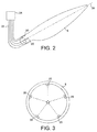
- FIG. 2 shows a wind turbine blade 5 with five pairs of strain sensors 20 positioned around a root end of the turbine blade, in accordance with an embodiment of the present invention.
- the pairs of strain sensors 20 are Fibre Bragg Grating (FBG) sensors within optical fibres, arranged in a "V" configuration.
- FBG Fibre Bragg Grating
- Each of the optical fibres 22 in which the FBGs are formed is connected to a signal processor 24.
- the signal processor 24 has an output 26, for providing strain measurements for use in diagnostics and/or control of the wind turbine.
- Figure 3 is a schematic cross section of the root of the blade shown in Figure 2 . It can be seen from Figure 3 that the FBGs 20 are disposed symmetrically around the longitudinal axis of the blade 5. The sensors are also positioned equidistant from the root end of the blade in the longitudinal direction.
- optical strain sensor may alternatively be used, such as long Period Gratings.
- Piezoelectric or semiconductor strain sensors may also be used, but for wind turbines it is preferable to use sensors that do not contain electrically conductive components, as electrically conductive components significantly increase the chances of lightening strikes on the wind turbine.
- the strain sensors are configured to allow for a determination of twisting torque about the longitudinal axis 26 of the blade 5.
- the signal processor 24 is configured to determine the twisting torque and to compare the twisting torque with a comparison value or predicted value for the torque based on one or more other measured parameters that correlate with twisting torque when the blade is operating under normal operating conditions.
- the bending moment on the blade is used as the parameter that correlates with the torque on the blade under normal operating conditions.
- Other parameters may be used, in addition, to improve correlation, or as an alternative to bending moment.
- measurement of wind speed, angle of attack of the blades and air temperature may be used as measured parameters.
- the comparison may be made with the measured torque or with a value derived from it. So, in this example, the comparison may be made between the measured torque and a predicted torque derived from the amount of bending moment on the blade, or it may be made between the bending moment (the comparison value) and value derived from the measured torque, or it may be made between a value derived from the measured torque and an expected value derived from the bending moment.
- the measured torque may be mathematically manipulated in some way before the comparison is made without affecting the ability to detect the presence of ice on the blade or damage to the blade.
- the comparison values with which comparison is made may be stored in a look-up table in a memory connected to the processor or may be calculated continually from the measured parameter or parameters.
- a look-up table in a memory connected to the processor or may be calculated continually from the measured parameter or parameters.
- complex computer models of the mechanical properties of the blade are used. These models may be based on finite element analysis, for example. These computer models can be used to provide the relationship between measured strains and the bending moment and twisting torque. They can also be used to provide the relationship between bending moment and twisting torque.
- values for populating a look-up table may be derived by operating the wind turbine under conditions in which it is known that no ice is present (herein referred to as normal operating conditions), or based on empirical data obtained from wind turbine blades of identical design.
- the look-up table may comprise torque values for a range of measured bending moments.
- the torque about the longitudinal axis of the blade falls below the comparison value by more than a predetermined amount, then it can be inferred that ice or some other matter that disrupts the flow of air across the blade is present. If the torque is higher than expected under normal operating conditions then some kind of structural damage to the blade may have occurred.
- the predetermined amount of difference used as the threshold for the determination of ice build-up can be based on the known resolution of the sensors used and/or a confidence value associated with the measurements used. There may also be an amount of ice or debris on the blade that can be safely tolerated. The predetermined amount may also be based on known variations in the relationship between the torque and the measured parameter due to environmental changes, such as air density or pressure, that typically remain within known limits.
- strain sensors 20 are placed round the root of the blade 5.
- the same sensors 20 are used to determine bending moment and torque.
- separate sets of sensors, of the same or different types may be used.
- the strain sensors 20 are positioned symmetrically around the longitudinal axis of the turbine blade 5, and are equidistant from the root end of the blade. Positioning the sensors symmetrically i.e. angularly equally spaced with respect to the longitudinal axis 26 of the blade, has advantages in the processing of strain measurements from the strain sensors. However, it should be clear that symmetrical disposition of the sensors is not essential for operation of the system in accordance with the present invention.
- the strain sensors are all placed in the round, homogenous part of a turbine blade close to the hub it is not necessary for all of the sensors to be equally spaced from the root end of the blade, as the measured strains will be the same irrespective of the longitudinal position of the sensors within that round cross-section portion of the blade.
- the blade cross-section at the position of the sensors is not symmetrical in any way, then the sensors should be arranged to be equidistant from the root and of the blade.
- Twisting torque and bending moments can be derived from the measured twisting and bending strains using the computer models described above, which are typically based on finite element analysis, or based on empirical data.
- the strain sensors are arranged in pairs. Each sensor in a pair is arranged to be sensitive to strain in a direction non-parallel to the longitudinal axis 26 of the blade. For ease of signal processing the sensors 20 in each pair are best arranged so that they are symmetrically disposed about a line parallel to the longitudinal axis of the blade.
- Figures 4a, 4b and 4c show possible configurations of the sensor pairs.
- Figure 4a shows "V" shaped pairs of sensors arranged on the root of the blade. Each pair of sensors may be FBGs, embedded in the same or different optical fibres. By comparing the strain measured by each sensor with the strain measured by the other sensor in the pair, both torque and longitudinal strain (from which bending moments may be derived) can be determined.
- Figure 4b shows “X” shaped pairs of sensors and
- Figure 4c shows "V” shaped pairs of sensors with greater spacing between the sensors in each pair. All of these arrangements operate on the same principle.
- the bending strain measured by each pair of sensors 20 is determined by its position.
- the bending strain measured by each pair of FBG is the strain in a radial direction, i.e. in a direction towards the centre of the root of the turbine blade 5, although it is derived from a measure of strain in a direction parallel to the longitudinal axis of the blade. This is clearly illustrated in Figure 3 by the dotted lines extending from each sensor.
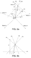
- Figure 5a is a graphical illustration of how the bending strain measurements from the sensors are used to provide a resultant bending strain measurement.
- the FBG strain sensors shown in Figures 2, and 3 are affected not only by bending strain but also by strain parallel to the longitudinal axis of the blade, by twisting strain and by temperature changes.
- the strain measurements from each sensor are added together and then divided by the number of sensors to provide an average strain. Contributions to the strain resulting from strain in a longitudinal direction of a turbine blade e.g. those due to centripetal force, will be the same for all of the sensors.
- the contribution to the strain measurements from bending forces acting in the plane defined by the sensors will add up to zero if the sensors are symmetrically disposed. Accordingly, subtraction of the average strain measurement from the strain measurement taken by each of the sensors will result in removal longitudinal strain from the strain measurement.
- Twisting strain is removed from the strain measurements by adding the strain measurements within each pair of sensors together.
- the resulting strain measurement for each pair of sensors is referred to herein as a bending strain measurement.
- Temperature compensation may still be required, and one or more temperature sensors may be provided on the blade for that purpose. Temperature sensors may also be provided to determine if conditions are such that ice formation is a possibility.
- the bending strain measurement from each of the sensors is illustrated as vector F1, F2, F3, F4 and F5 respectively.
- the bending strain measured by each of the sensors can be understood as a force that points in the radial direction defined by the mounting position of the sensor.
- the bending strains are illustrated in Figure 5a as emanating from a single point, the centre of the root of the blade.
- the actual or resultant bending strain is illustrated by vector R which comprises both edgewise and flapwise components, and from which the edgewise and flapwise components can be simply derived.
- the resultant strain R can be determined from the five bending strain measurements F1 to F5.
- the bending strain measured by each strain sensor is the component of the resultant bending strain in the radial direction defined by the position of the sensor. This is clearly shown in Figure 4a where lines P1 to P5 are drawn from the resultant bending strain R to each of the measured bending strains F1 to F5, at right angles to each of the measured bending strains. So one way to calculate the resultant bending strain from the measured bending strain is to simply determine where the lines P1 to P5 cross. This can be understood algebraically as solving simultaneous equations for two variables, i.e. the magnitude and direction of the resultant bending strain, from five simultaneous equations.
- the individual strain measurements may be converted into bending moments before calculating resultant bending moments and average resultant bending moment, rather than calculating resultant bending strains and an average resultant bending strain directly from the strain measurements. This is useful if the relationship between bending strain and bending moment is not the same for all of the sensors. This might be the case if the blade cross-section at the position of the sensors is not symmetrical and homogenous.
- is the magnitude of the strain F N detected by each strain sensor.
- the resultant bending strain can be calculated as an average of all of the possible solutions i.e. an average of all of the crossing points of lines P1 to P5 in Figure 5b .
- the average can be a simple mean for the magnitude and direction, calculated by summing and dividing all of the possible solutions.
- a two-dimensional normal distribution can be fitted to the results, which provides not only a convenient average but also a convenient measure of confidence in the result, based on the standard deviation from the mean. Other measures of confidence or accuracy in the resultant bending strain are also possible, such a simple average of the deviation of each result from the mean.
- Providing a measure of confidence in the average resultant bending strain can be extremely useful. It allows the basis for a decision on whether to stop the turbine to remove ice or clean the blades to factor in how accurate the measurements are. If the confidence value is high that there is a tolerable amount of ice on the turbine blade then the turbine blade can continue to operate. If the confidence value is low, a greater margin of error can be used and any amount of ice close to the maximum tolerable level may require the turbine to be stopped.
- FIG. 6a is a similar diagram to that of Figure 5a , but for a different set of example measurements.
- the bending strain measurements (from which non bending strain contributions have been subtracted) are represented by lines F1 to F5.
- Perpendicular lines P1 to P5 have been drawn from the ends of each of F1 to F5, and the crossing points of lines P1 to P5 represent possible solutions for the resultant bending strain R. It can be seen in Figure 5a that the result obtained from sensor 1 i.e. bending strain F1, provides very different solutions from the results obtained using combinations of the other sensors.
- the line P1 does not cross the lines P2, P3, P4 or P5 near the area in which lines P2 to P5 cross each other.
- Figure 6b is a detailed view of the crossing points of the lines P1 to P5 in Figure 6a .
- the strain measurement F1 is clearly erroneous and should be ignored.
- the resultant bending strain can be better calculated using only the measurements from sensors 2 to 5 i.e. bending strains F2 to F5 as illustrated.
- the solutions for resultant bending strain R provided using that strain measurement are compared to the average solution for R. If the difference between the results using one of the strain sensors are all (or alternatively on average) greater than a threshold difference value, then measurements from that strain sensor can be discarded and the calculations (including those calculations removing non-bending strain contributions from the strain measurements) are repeated without input from the faulty sensor.
- the threshold value can be set as an absolute value or as a number of standard deviations away from the mean value or any other suitable method, such as a proportion of the average resultant bending strain.
- This process of comparing each result with an average result can be fully automated within the signal processor and may provide a confidence value for each sensor and provide an alert when a faulty sensor is detected i.e. when the threshold level is exceeded. This allows the system to provide more accurate results and provide automated diagnostics.
- any suitable analysis methods may be used to give a resultant bending strain and confidence values both in the average bending strain and in the measurement from each individual sensor.
- sufficient strain sensors need to be provided.
- the minimum number of FBG strain sensors needed to provide a resultant bending strain measurement in two dimensions is three FBG sensors.
- more than three strain sensors need to be provided.
- five or more sensors are provided. The more sensors that are provided the greater the resolution, precision and confidence of measurement that can be obtained and the lower the threshold for discarding erroneous measurements can be set.
Landscapes
- Engineering & Computer Science (AREA)
- Physics & Mathematics (AREA)
- General Physics & Mathematics (AREA)
- Aviation & Aerospace Engineering (AREA)
- Sustainable Development (AREA)
- Life Sciences & Earth Sciences (AREA)
- Sustainable Energy (AREA)
- Chemical & Material Sciences (AREA)
- Combustion & Propulsion (AREA)
- Mechanical Engineering (AREA)
- General Engineering & Computer Science (AREA)
- Electromagnetism (AREA)
- Wind Motors (AREA)
- Length Measuring Devices By Optical Means (AREA)
Claims (17)
- Verfahren zum Überwachen einer Biegebeanspruchung an einem Windturbinenblatt, umfassend:Anordnen von zumindest drei Beanspruchungssensoren auf dem Turbinenblatt, wobei in Gebrauch jeder Beanspruchungssensor eine Beanspruchungsmessung bereitstellt, wobei die Beanspruchungssensoren so angeordnet sind, das randseitiges Biegen und Biegen in Schlagrichtung aus den Beanspruchungsmessungen bestimmt werden kann;Berechnen einer Mehrzahl von resultierenden Biegebeanspruchungen unter Verwendung der Beanspruchungsmessungen;Berechnen einer mittleren resultierenden Biegebeanspruchung aus der einer Mehrzahl von resultierenden Biegebeanspruchungen; undBerechnen eines Vertrauenswertes für einen ersten Sensor basierend auf einem Vergleich der resultierenden Biegebeanspruchungen abgeleitet von der Beanspruchungsmessung des ersten Sensors mit der mittleren resultierenden Biegebeanspruchung.
- Verfahren nach Anspruch 1, wobei die individuellen Beanspruchungsmessungen in Biegemomente umgewandelt werden bevor resultierende Biegemomente und mittlere resultierende Biegemomente berechnet werden.
- Verfahren nach einem der Ansprüche 1 oder 2, wobei der Vertrauenswert auf einer absoluten Differenz zwischen den resultierenden Biegebeanspruchungen abgeleitet von der Messung des ersten Sensors mit der mittleren resultierenden Biegebeanspruchung basiert wird.
- Verfahren nach einem der Ansprüche 1 oder 2, wobei der Vertrauenswert auf einer Anzahl von Standardabweichungen der Biegebeanspruchungsmessung des ersten Sensors von der mittleren resultierenden Biegebeanspruchung basiert wird.
- Verfahren nach einem der vorhergehenden Ansprüche, weiterhin umfassend
Anordnen von zumindest vier Beanspruchungssensoren auf dem Turbinenblatt; und weiterhin umfassend den Schritt:Vergleichen des Vertrauenswertes mit einem Vertrauensschwellwert, und, wenn der Vertrauenswert kleiner ist, als der Vertrauensschwellwert, Neuberechnen einer mittleren resultierenden Biegebeanspruchung ohne Verwenden der Beanspruchungsmessung des ersten Beanspruchungssensors. - Verfahren nach einem der vorhergehenden Ansprüche, weiterhin umfassend den Schritt Berechnen eines Vertrauenswertes für die mittlere resultierende Biegebeanspruchung.
- Verfahren nach Anspruch 6, wobei der Vertrauenswert für die mittlere resultierende Biegebeanspruchung auf einem Vergleich der Mehrzahl von resultierenden Biegebeanspruchungen miteinander oder mit der mittleren resultierenden Biegebeanspruchung basiert wird.
- Verfahren nach einem der vorhergehenden Ansprüche, weiterhin umfassend Berechnen nicht biegender Komponenten der Beanspruchungsmessungen der Beanspruchungssensoren.
- Verfahren zum Überwachen einer Biegebeanspruchung an einem Windturbinenblatt, umfassend:Anordnen von zumindest drei Beanspruchungssensoren auf dem Turbinenblatt, wobei in Gebrauch jeder Beanspruchungssensor eine Beanspruchungsmessung bereitstellt, wobei die Beanspruchungssensoren so angeordnet sind, das randseitiges Biegen und Biegen in Schlagrichtung aus den Beanspruchungsmessungen bestimmt werden kann;Berechnen einer Mehrzahl von resultierenden Biegebeanspruchungen unter Verwendung der Beanspruchungsmessungen;Berechnen einer mittleren resultierenden Biegebeanspruchung aus der einer Mehrzahl von resultierenden Biegebeanspruchungen; undBerechnen eines Vertrauenswertes für die mittlere resultierende Biegebeanspruchung basierend auf einem Vergleich der Mehrzahl von resultierenden Biegebeanspruchungen miteinander oder mit der mittleren resultierenden Biegebeanspruchung.
- Verfahren nach einem der vorhergehenden Ansprüche, wobei jede resultierende Biegebeanspruchung von Biegebeanspruchungsmessungen, die von einem unterschiedlichen Paar von Beanspruchungssensoren ausgeführt wurden, berechnet wird, wobei die Beanspruchungssensoren in jedem Paar Biegebeanspruchungsmessungen in zueinander nicht parallelen Richtungen vorsehen.
- Verfahren nach einem der vorhergehenden Ansprüche, wobei die Sensoren alle im Wesentlichen abstandsgleich von dem Fußende des Blattes angeordnet sind.
- System zum Überwachen einer Biegebeanspruchung an einem Windturbinenblatt, umfassend:zumindest drei Beanspruchungssensoren angeordnet auf dem Turbinenblatt, wobei in Gebrauch jeder Beanspruchungssensor eine Beanspruchungsmessung bereitstellt, wobei die Beanspruchungssensoren so angeordnet sind, das randseitiges Biegen und Biegen in Schlagrichtung aus den Beanspruchungsmessungen bestimmt werden kann; undeinen Signalprozessor verbunden mit jedem der Beanspruchungssensoren, der Signalprozessor ausgebildet zum:Berechnen einer Mehrzahl von resultierenden Biegebeanspruchungen unter Verwendung der Beanspruchungsmessungen;Berechnen einer mittleren resultierenden Biegebeanspruchung aus der einer Mehrzahl von resultierenden Biegebeanspruchungen; undBerechnen eines Vertrauenswertes für einen ersten Sensor basierend auf einem Vergleich der resultierenden Biegebeanspruchungen abgeleitet von der Beanspruchungsmessung des ersten Sensors mit der mittleren resultierenden Biegebeanspruchung.
- System nach Anspruch 12, wobei das System zumindest vier Beanspruchungssensoren auf dem Turbinenblatt umfasst, und wobei der Signalprozessor weiterhin ausgebildet ist zum Vergleichen des Vertrauenswertes mit einem Vertrauensschwellwert, und, wenn der Vertrauenswert kleiner ist, als der Vertrauensschwellwert, Neuberechnen einer mittleren resultierenden Biegebeanspruchung ohne Verwenden der Beanspruchungsmessung des ersten Beanspruchungssensors.
- System nach einem der Ansprüche 12 oder 13, wobei der Signalprozessor weiterhin ausgebildet ist zum Berechnen eines Vertrauenswertes für die mittlere resultierende Biegebeanspruchung.
- System nach Anspruch 14, wobei der Signalprozessor ausgebildet ist zum Berechnen des Vertrauenswertes für die mittlere resultierende Biegebeanspruchung basierend auf einem Vergleich der Mehrzahl von resultierenden Biegebeanspruchungen miteinander oder mit der mittleren resultierenden Biegebeanspruchung.
- System zum Überwachen einer Biegebeanspruchung an einem Windturbinenblatt, umfassend:zumindest drei Beanspruchungssensoren angeordnet auf dem Turbinenblatt, wobei in Gebrauch jeder Beanspruchungssensor eine Beanspruchungsmessung bereitstellt, wobei die Beanspruchungssensoren so angeordnet sind, das randseitiges Biegen und Biegen in Schlagrichtung aus den Beanspruchungsmessungen bestimmt werden kann; undeinen Signalprozessor verbunden mit jedem der Beanspruchungssensoren, der Signalprozessor ausgebildet zum:Berechnen einer Mehrzahl von resultierenden Biegebeanspruchungen unter Verwendung der Beanspruchungsmessungen;Berechnen einer mittleren resultierenden Biegebeanspruchung aus der einer Mehrzahl von resultierenden Biegebeanspruchungen; undBerechnen eines Vertrauenswertes für die mittlere resultierende Biegebeanspruchung basierend auf einem Vergleich der Mehrzahl von resultierenden Biegebeanspruchungen miteinander oder mit der mittleren resultierenden Biegebeanspruchung.
- System nach Anspruch 16, wobei die Mehrzahl von Beanspruchungssensoren zumindest ein Paar von nebeneinanderliegenden Beanspruchungssensoren umfasst, die auf dem Blatt so angeordnet sind, dass ihre sensitiven Achsen nicht parallel mit der Längsachse des Blattes sind.
Applications Claiming Priority (3)
| Application Number | Priority Date | Filing Date | Title |
|---|---|---|---|
| US36407910P | 2010-07-14 | 2010-07-14 | |
| GB1021226.4A GB2482038B (en) | 2010-07-14 | 2010-07-14 | Ice detection method and system for wind turbine blades |
| PCT/DK2011/050275 WO2012007005A2 (en) | 2010-07-14 | 2011-07-12 | Ice detection method and system for wind turbine blades |
Publications (3)
| Publication Number | Publication Date |
|---|---|
| EP2593671A2 EP2593671A2 (de) | 2013-05-22 |
| EP2593671B1 true EP2593671B1 (de) | 2016-06-29 |
| EP2593671B8 EP2593671B8 (de) | 2016-09-21 |
Family
ID=43567199
Family Applications (1)
| Application Number | Title | Priority Date | Filing Date |
|---|---|---|---|
| EP11733561.2A Not-in-force EP2593671B8 (de) | 2010-07-14 | 2011-07-12 | Verfahren und system zur beobachtung der biegebeanspruchung von windturbinenschaufeln |
Country Status (5)
| Country | Link |
|---|---|
| US (1) | US9032807B2 (de) |
| EP (1) | EP2593671B8 (de) |
| ES (1) | ES2587230T3 (de) |
| GB (1) | GB2482038B (de) |
| WO (1) | WO2012007005A2 (de) |
Families Citing this family (13)
| Publication number | Priority date | Publication date | Assignee | Title |
|---|---|---|---|---|
| GB2482009B (en) | 2010-07-14 | 2014-07-23 | Vestas Wind Sys As | Ice detection and system for wind turbine blades |
| WO2015014366A1 (en) * | 2013-07-30 | 2015-02-05 | Vestas Wind Systems A/S | Wind turbine operating method and device based on load and acceleration measurements in the blade |
| CN107810321B (zh) * | 2015-06-30 | 2020-08-11 | 维斯塔斯风力系统集团公司 | 测量风力涡轮机上的载荷的方法 |
| CN106338242B (zh) * | 2015-07-15 | 2019-01-29 | 成都阜特科技股份有限公司 | 一种风力发电机组叶片覆冰量测量方法及其测量装置 |
| JP6452583B2 (ja) * | 2015-09-24 | 2019-01-16 | 株式会社シルフィード | 小形風力発電機のブレーキ制御方法及び小形風力発電機 |
| CN107061160A (zh) * | 2017-04-26 | 2017-08-18 | 浙江运达风电股份有限公司 | 一种基于叶片载荷检测的风力发电机组叶片冰载运行安全控制方法及系统 |
| US10539119B2 (en) | 2017-07-10 | 2020-01-21 | WindESCo, Inc. | System and method for augmenting control of a wind turbine assembly |
| DE102017115927A1 (de) * | 2017-07-14 | 2019-01-17 | fos4X GmbH | Dehnungs- und Vibrations-Messsystem zur Überwachung von Rotorblättern |
| CN109958588B (zh) * | 2017-12-14 | 2020-08-07 | 北京金风科创风电设备有限公司 | 结冰预测方法、装置、存储介质、模型生成方法及装置 |
| ES2985392T3 (es) | 2019-11-25 | 2024-11-05 | Vestas Wind Sys As | Reducción de cargas máximas fuera de la vertical en una turbina eólica |
| WO2021150239A1 (en) * | 2020-01-24 | 2021-07-29 | General Electric Company | System and method for controlling a wind turbine |
| CN113029405B (zh) * | 2021-02-04 | 2022-04-22 | 南京航空航天大学 | 基于光纤应变组合桥路的桨叶弯矩解耦与标定方法 |
| EP4239189A1 (de) | 2022-03-02 | 2023-09-06 | General Electric Renovables España S.L. | Schwingungen in windturbinen |
Family Cites Families (18)
| Publication number | Priority date | Publication date | Assignee | Title |
|---|---|---|---|---|
| US6915237B2 (en) * | 2002-05-14 | 2005-07-05 | Analysis And Measurement Services Corporation | Integrated system for verifying the performance and health of instruments and processes |
| US7246991B2 (en) * | 2002-09-23 | 2007-07-24 | John Vanden Bosche | Wind turbine blade deflection control system |
| US7086834B2 (en) * | 2004-06-10 | 2006-08-08 | General Electric Company | Methods and apparatus for rotor blade ice detection |
| US7822560B2 (en) | 2004-12-23 | 2010-10-26 | General Electric Company | Methods and apparatuses for wind turbine fatigue load measurement and assessment |
| ES2386895T3 (es) | 2005-07-28 | 2012-09-05 | General Electric Company | Sistema de detección de congelación para un aerogenerador |
| DE102006036157B4 (de) * | 2006-08-01 | 2016-09-15 | Senvion Gmbh | Kalibrierverfahren |
| US7677075B2 (en) * | 2006-09-29 | 2010-03-16 | General Electric Company | Methods and apparatus for evaluating sensors and/or for controlling operation of an apparatus that includes a sensor |
| DE102007007047A1 (de) | 2007-02-08 | 2008-08-14 | Hottinger Baldwin Messtechnik Gmbh | Vorrichtung zur Erfassung von Schwingungen oder Durchbiegungen von Rotorblättern einer Windkraftanlage |
| US20090246019A1 (en) * | 2007-05-04 | 2009-10-01 | Mark Volanthen | Wind turbine monitoring |
| GB2454253B (en) * | 2007-11-02 | 2011-02-16 | Insensys Ltd | Strain sensors |
| ATE528504T1 (de) | 2007-11-07 | 2011-10-15 | Vestas Wind Sys As | Diagnose von anstellwinkel- und lastfehlern |
| KR20100088676A (ko) | 2007-11-21 | 2010-08-10 | 볼보 컨스트럭션 이큅먼트 에이비 | 센서를 보정하는 방법 |
| US8215905B2 (en) * | 2007-12-31 | 2012-07-10 | General Electric Corporation | Methods and apparatus for error reduction in rotor loading measurements |
| ES2524043T3 (es) * | 2008-03-07 | 2014-12-03 | Vestas Wind Systems A/S | Un sistema de control y un procedimiento para controlar una turbina eólica |
| NL2001878C2 (nl) | 2008-08-07 | 2010-02-09 | Stichting Energie | Systeem en werkwijze voor compensatie van rotoronbalans voor een windturbine. |
| GB2463696A (en) * | 2008-09-22 | 2010-03-24 | Vestas Wind Sys As | Edge-wise bending insensitive strain sensor system |
| DE102009009039A1 (de) | 2009-02-16 | 2010-08-19 | Prüftechnik Dieter Busch AG | Windenergieanlage mit Überwachungssensoren |
| GB2482009B (en) * | 2010-07-14 | 2014-07-23 | Vestas Wind Sys As | Ice detection and system for wind turbine blades |
-
2010
- 2010-07-14 GB GB1021226.4A patent/GB2482038B/en not_active Expired - Fee Related
-
2011
- 2011-07-12 EP EP11733561.2A patent/EP2593671B8/de not_active Not-in-force
- 2011-07-12 US US13/809,984 patent/US9032807B2/en not_active Expired - Fee Related
- 2011-07-12 WO PCT/DK2011/050275 patent/WO2012007005A2/en not_active Ceased
- 2011-07-12 ES ES11733561.2T patent/ES2587230T3/es active Active
Also Published As
| Publication number | Publication date |
|---|---|
| WO2012007005A3 (en) | 2012-05-10 |
| US9032807B2 (en) | 2015-05-19 |
| WO2012007005A2 (en) | 2012-01-19 |
| GB2482038B (en) | 2014-07-23 |
| US20130174664A1 (en) | 2013-07-11 |
| EP2593671A2 (de) | 2013-05-22 |
| ES2587230T3 (es) | 2016-10-21 |
| EP2593671B8 (de) | 2016-09-21 |
| GB2482038A (en) | 2012-01-18 |
| GB201021226D0 (en) | 2011-01-26 |
Similar Documents
| Publication | Publication Date | Title |
|---|---|---|
| EP2593672B1 (de) | Verfahren und system zur erkennung von vereisung auf windturbinenschaufeln | |
| EP2593671B1 (de) | Verfahren und system zur beobachtung der biegebeanspruchung von windturbinenschaufeln | |
| Oh et al. | A novel method and its field tests for monitoring and diagnosing blade health for wind turbines | |
| EP2886853B1 (de) | Überwachungssystem und Überwachungsverfahren für einen Windturbinengenerator | |
| CN104641107B (zh) | 用于监控转子叶片的状态的方法和装置 | |
| US20100004878A1 (en) | Wind turbine monitoring | |
| EP2956663B1 (de) | Erkennung von anomalien in einer klingenstruktur | |
| US11448195B2 (en) | Sensor arrangement for a wind turbine | |
| CN112796957B (zh) | 一种风机叶片的检测方法和装置以及设备 | |
| EP2112375A2 (de) | Feststellung von Vereisung für eine Windturbine | |
| CN105604806B (zh) | 风力发电机的塔架状态监测方法和系统 | |
| EP3415753B1 (de) | Anomalieüberwachungsvorrichtung und anomalieüberwachungsverfahren für windpark | |
| EP3062131B1 (de) | Verfahren zur detektion von schäden an windturbinenschaufel und windturbine | |
| CN106643906A (zh) | 变桨轴承的监测方法和监测系统 | |
| CN105822508B (zh) | 一种监测风力发电设备的叶片形变的系统 | |
| EP3361093B1 (de) | Verfahren zur detektion von schäden an windturbinenschaufeln und windturbinen | |
| CN115126665A (zh) | 风力发电机的风机叶片监测方法及装置、存储介质、风力发电机 | |
| US20210148336A1 (en) | A method for determining wind turbine blade edgewise load recurrence | |
| CN212254562U (zh) | 汽轮机动叶片振动监测系统 | |
| Ovenden et al. | Real-time monitoring of wind turbine blade alignment using laser displacement and strain measurement | |
| Jeżyński et al. | Stress diagnostic and monitoring of blade in rotational motion | |
| Marsh | In-service monitoring of turbine blades | |
| Xue et al. | Consistency Monitoring of Wind Turbine Blade Loads Based on MEMS Optical Fiber Sensing | |
| GB2483659A (en) | Strain sensor with strain attenuating substrate | |
| CN119532132A (zh) | 风力发电机偏航传动系统运行状况的故障检测系统及方法 |
Legal Events
| Date | Code | Title | Description |
|---|---|---|---|
| PUAI | Public reference made under article 153(3) epc to a published international application that has entered the european phase |
Free format text: ORIGINAL CODE: 0009012 |
|
| 17P | Request for examination filed |
Effective date: 20130214 |
|
| AK | Designated contracting states |
Kind code of ref document: A2 Designated state(s): AL AT BE BG CH CY CZ DE DK EE ES FI FR GB GR HR HU IE IS IT LI LT LU LV MC MK MT NL NO PL PT RO RS SE SI SK SM TR |
|
| DAX | Request for extension of the european patent (deleted) | ||
| REG | Reference to a national code |
Ref country code: DE Ref legal event code: R079 Ref document number: 602011027746 Country of ref document: DE Free format text: PREVIOUS MAIN CLASS: F03D0007040000 Ipc: F03D0017000000 |
|
| GRAP | Despatch of communication of intention to grant a patent |
Free format text: ORIGINAL CODE: EPIDOSNIGR1 |
|
| RIC1 | Information provided on ipc code assigned before grant |
Ipc: G01M 5/00 20060101ALI20160108BHEP Ipc: G01L 1/24 20060101ALI20160108BHEP Ipc: F03D 80/40 20160101ALI20160108BHEP Ipc: F03D 17/00 20160101AFI20160108BHEP |
|
| INTG | Intention to grant announced |
Effective date: 20160201 |
|
| GRAS | Grant fee paid |
Free format text: ORIGINAL CODE: EPIDOSNIGR3 |
|
| GRAA | (expected) grant |
Free format text: ORIGINAL CODE: 0009210 |
|
| AK | Designated contracting states |
Kind code of ref document: B1 Designated state(s): AL AT BE BG CH CY CZ DE DK EE ES FI FR GB GR HR HU IE IS IT LI LT LU LV MC MK MT NL NO PL PT RO RS SE SI SK SM TR |
|
| REG | Reference to a national code |
Ref country code: GB Ref legal event code: FG4D |
|
| REG | Reference to a national code |
Ref country code: CH Ref legal event code: EP |
|
| REG | Reference to a national code |
Ref country code: AT Ref legal event code: REF Ref document number: 809326 Country of ref document: AT Kind code of ref document: T Effective date: 20160715 |
|
| REG | Reference to a national code |
Ref country code: IE Ref legal event code: FG4D |
|
| REG | Reference to a national code |
Ref country code: FR Ref legal event code: PLFP Year of fee payment: 6 |
|
| RAP2 | Party data changed (patent owner data changed or rights of a patent transferred) |
Owner name: VESTAS WIND SYSTEMS A/S |
|
| REG | Reference to a national code |
Ref country code: DE Ref legal event code: R096 Ref document number: 602011027746 Country of ref document: DE |
|
| REG | Reference to a national code |
Ref country code: ES Ref legal event code: FG2A Ref document number: 2587230 Country of ref document: ES Kind code of ref document: T3 Effective date: 20161021 |
|
| REG | Reference to a national code |
Ref country code: LT Ref legal event code: MG4D |
|
| PG25 | Lapsed in a contracting state [announced via postgrant information from national office to epo] |
Ref country code: FI Free format text: LAPSE BECAUSE OF FAILURE TO SUBMIT A TRANSLATION OF THE DESCRIPTION OR TO PAY THE FEE WITHIN THE PRESCRIBED TIME-LIMIT Effective date: 20160629 Ref country code: LT Free format text: LAPSE BECAUSE OF FAILURE TO SUBMIT A TRANSLATION OF THE DESCRIPTION OR TO PAY THE FEE WITHIN THE PRESCRIBED TIME-LIMIT Effective date: 20160629 Ref country code: NO Free format text: LAPSE BECAUSE OF FAILURE TO SUBMIT A TRANSLATION OF THE DESCRIPTION OR TO PAY THE FEE WITHIN THE PRESCRIBED TIME-LIMIT Effective date: 20160929 |
|
| REG | Reference to a national code |
Ref country code: NL Ref legal event code: MP Effective date: 20160629 |
|
| PG25 | Lapsed in a contracting state [announced via postgrant information from national office to epo] |
Ref country code: LV Free format text: LAPSE BECAUSE OF FAILURE TO SUBMIT A TRANSLATION OF THE DESCRIPTION OR TO PAY THE FEE WITHIN THE PRESCRIBED TIME-LIMIT Effective date: 20160629 Ref country code: SE Free format text: LAPSE BECAUSE OF FAILURE TO SUBMIT A TRANSLATION OF THE DESCRIPTION OR TO PAY THE FEE WITHIN THE PRESCRIBED TIME-LIMIT Effective date: 20160629 Ref country code: GR Free format text: LAPSE BECAUSE OF FAILURE TO SUBMIT A TRANSLATION OF THE DESCRIPTION OR TO PAY THE FEE WITHIN THE PRESCRIBED TIME-LIMIT Effective date: 20160930 Ref country code: RS Free format text: LAPSE BECAUSE OF FAILURE TO SUBMIT A TRANSLATION OF THE DESCRIPTION OR TO PAY THE FEE WITHIN THE PRESCRIBED TIME-LIMIT Effective date: 20160629 Ref country code: NL Free format text: LAPSE BECAUSE OF FAILURE TO SUBMIT A TRANSLATION OF THE DESCRIPTION OR TO PAY THE FEE WITHIN THE PRESCRIBED TIME-LIMIT Effective date: 20160629 Ref country code: HR Free format text: LAPSE BECAUSE OF FAILURE TO SUBMIT A TRANSLATION OF THE DESCRIPTION OR TO PAY THE FEE WITHIN THE PRESCRIBED TIME-LIMIT Effective date: 20160629 |
|
| REG | Reference to a national code |
Ref country code: AT Ref legal event code: MK05 Ref document number: 809326 Country of ref document: AT Kind code of ref document: T Effective date: 20160629 |
|
| PG25 | Lapsed in a contracting state [announced via postgrant information from national office to epo] |
Ref country code: BE Free format text: LAPSE BECAUSE OF NON-PAYMENT OF DUE FEES Effective date: 20160731 |
|
| PG25 | Lapsed in a contracting state [announced via postgrant information from national office to epo] |
Ref country code: CZ Free format text: LAPSE BECAUSE OF FAILURE TO SUBMIT A TRANSLATION OF THE DESCRIPTION OR TO PAY THE FEE WITHIN THE PRESCRIBED TIME-LIMIT Effective date: 20160629 Ref country code: IS Free format text: LAPSE BECAUSE OF FAILURE TO SUBMIT A TRANSLATION OF THE DESCRIPTION OR TO PAY THE FEE WITHIN THE PRESCRIBED TIME-LIMIT Effective date: 20161029 Ref country code: RO Free format text: LAPSE BECAUSE OF FAILURE TO SUBMIT A TRANSLATION OF THE DESCRIPTION OR TO PAY THE FEE WITHIN THE PRESCRIBED TIME-LIMIT Effective date: 20160629 Ref country code: IT Free format text: LAPSE BECAUSE OF FAILURE TO SUBMIT A TRANSLATION OF THE DESCRIPTION OR TO PAY THE FEE WITHIN THE PRESCRIBED TIME-LIMIT Effective date: 20160629 Ref country code: SK Free format text: LAPSE BECAUSE OF FAILURE TO SUBMIT A TRANSLATION OF THE DESCRIPTION OR TO PAY THE FEE WITHIN THE PRESCRIBED TIME-LIMIT Effective date: 20160629 Ref country code: EE Free format text: LAPSE BECAUSE OF FAILURE TO SUBMIT A TRANSLATION OF THE DESCRIPTION OR TO PAY THE FEE WITHIN THE PRESCRIBED TIME-LIMIT Effective date: 20160629 |
|
| PG25 | Lapsed in a contracting state [announced via postgrant information from national office to epo] |
Ref country code: BE Free format text: LAPSE BECAUSE OF FAILURE TO SUBMIT A TRANSLATION OF THE DESCRIPTION OR TO PAY THE FEE WITHIN THE PRESCRIBED TIME-LIMIT Effective date: 20160629 Ref country code: SM Free format text: LAPSE BECAUSE OF FAILURE TO SUBMIT A TRANSLATION OF THE DESCRIPTION OR TO PAY THE FEE WITHIN THE PRESCRIBED TIME-LIMIT Effective date: 20160629 Ref country code: PT Free format text: LAPSE BECAUSE OF FAILURE TO SUBMIT A TRANSLATION OF THE DESCRIPTION OR TO PAY THE FEE WITHIN THE PRESCRIBED TIME-LIMIT Effective date: 20161031 Ref country code: PL Free format text: LAPSE BECAUSE OF FAILURE TO SUBMIT A TRANSLATION OF THE DESCRIPTION OR TO PAY THE FEE WITHIN THE PRESCRIBED TIME-LIMIT Effective date: 20160629 Ref country code: AT Free format text: LAPSE BECAUSE OF FAILURE TO SUBMIT A TRANSLATION OF THE DESCRIPTION OR TO PAY THE FEE WITHIN THE PRESCRIBED TIME-LIMIT Effective date: 20160629 |
|
| REG | Reference to a national code |
Ref country code: CH Ref legal event code: PL |
|
| REG | Reference to a national code |
Ref country code: DE Ref legal event code: R097 Ref document number: 602011027746 Country of ref document: DE |
|
| PG25 | Lapsed in a contracting state [announced via postgrant information from national office to epo] |
Ref country code: CH Free format text: LAPSE BECAUSE OF NON-PAYMENT OF DUE FEES Effective date: 20160731 Ref country code: LI Free format text: LAPSE BECAUSE OF NON-PAYMENT OF DUE FEES Effective date: 20160731 |
|
| REG | Reference to a national code |
Ref country code: IE Ref legal event code: MM4A |
|
| PLBE | No opposition filed within time limit |
Free format text: ORIGINAL CODE: 0009261 |
|
| STAA | Information on the status of an ep patent application or granted ep patent |
Free format text: STATUS: NO OPPOSITION FILED WITHIN TIME LIMIT |
|
| PG25 | Lapsed in a contracting state [announced via postgrant information from national office to epo] |
Ref country code: DK Free format text: LAPSE BECAUSE OF FAILURE TO SUBMIT A TRANSLATION OF THE DESCRIPTION OR TO PAY THE FEE WITHIN THE PRESCRIBED TIME-LIMIT Effective date: 20160629 |
|
| 26N | No opposition filed |
Effective date: 20170330 |
|
| REG | Reference to a national code |
Ref country code: FR Ref legal event code: PLFP Year of fee payment: 7 |
|
| PG25 | Lapsed in a contracting state [announced via postgrant information from national office to epo] |
Ref country code: IE Free format text: LAPSE BECAUSE OF NON-PAYMENT OF DUE FEES Effective date: 20160712 |
|
| PG25 | Lapsed in a contracting state [announced via postgrant information from national office to epo] |
Ref country code: BG Free format text: LAPSE BECAUSE OF FAILURE TO SUBMIT A TRANSLATION OF THE DESCRIPTION OR TO PAY THE FEE WITHIN THE PRESCRIBED TIME-LIMIT Effective date: 20160929 Ref country code: LU Free format text: LAPSE BECAUSE OF NON-PAYMENT OF DUE FEES Effective date: 20160712 Ref country code: SI Free format text: LAPSE BECAUSE OF FAILURE TO SUBMIT A TRANSLATION OF THE DESCRIPTION OR TO PAY THE FEE WITHIN THE PRESCRIBED TIME-LIMIT Effective date: 20160629 |
|
| PG25 | Lapsed in a contracting state [announced via postgrant information from national office to epo] |
Ref country code: HU Free format text: LAPSE BECAUSE OF FAILURE TO SUBMIT A TRANSLATION OF THE DESCRIPTION OR TO PAY THE FEE WITHIN THE PRESCRIBED TIME-LIMIT; INVALID AB INITIO Effective date: 20110712 Ref country code: CY Free format text: LAPSE BECAUSE OF FAILURE TO SUBMIT A TRANSLATION OF THE DESCRIPTION OR TO PAY THE FEE WITHIN THE PRESCRIBED TIME-LIMIT Effective date: 20160629 |
|
| PG25 | Lapsed in a contracting state [announced via postgrant information from national office to epo] |
Ref country code: TR Free format text: LAPSE BECAUSE OF FAILURE TO SUBMIT A TRANSLATION OF THE DESCRIPTION OR TO PAY THE FEE WITHIN THE PRESCRIBED TIME-LIMIT Effective date: 20160629 Ref country code: MT Free format text: LAPSE BECAUSE OF NON-PAYMENT OF DUE FEES Effective date: 20160731 Ref country code: MC Free format text: LAPSE BECAUSE OF FAILURE TO SUBMIT A TRANSLATION OF THE DESCRIPTION OR TO PAY THE FEE WITHIN THE PRESCRIBED TIME-LIMIT Effective date: 20160629 Ref country code: MK Free format text: LAPSE BECAUSE OF FAILURE TO SUBMIT A TRANSLATION OF THE DESCRIPTION OR TO PAY THE FEE WITHIN THE PRESCRIBED TIME-LIMIT Effective date: 20160629 |
|
| REG | Reference to a national code |
Ref country code: FR Ref legal event code: PLFP Year of fee payment: 8 |
|
| PG25 | Lapsed in a contracting state [announced via postgrant information from national office to epo] |
Ref country code: AL Free format text: LAPSE BECAUSE OF FAILURE TO SUBMIT A TRANSLATION OF THE DESCRIPTION OR TO PAY THE FEE WITHIN THE PRESCRIBED TIME-LIMIT Effective date: 20160629 |
|
| PGFP | Annual fee paid to national office [announced via postgrant information from national office to epo] |
Ref country code: GB Payment date: 20180731 Year of fee payment: 8 |
|
| GBPC | Gb: european patent ceased through non-payment of renewal fee |
Effective date: 20190712 |
|
| PG25 | Lapsed in a contracting state [announced via postgrant information from national office to epo] |
Ref country code: GB Free format text: LAPSE BECAUSE OF NON-PAYMENT OF DUE FEES Effective date: 20190712 |
|
| PG25 | Lapsed in a contracting state [announced via postgrant information from national office to epo] |
Ref country code: FR Free format text: LAPSE BECAUSE OF NON-PAYMENT OF DUE FEES Effective date: 20190731 |
|
| PGFP | Annual fee paid to national office [announced via postgrant information from national office to epo] |
Ref country code: ES Payment date: 20230816 Year of fee payment: 13 |
|
| PGFP | Annual fee paid to national office [announced via postgrant information from national office to epo] |
Ref country code: DE Payment date: 20230726 Year of fee payment: 13 |
|
| REG | Reference to a national code |
Ref country code: DE Ref legal event code: R119 Ref document number: 602011027746 Country of ref document: DE |
|
| PG25 | Lapsed in a contracting state [announced via postgrant information from national office to epo] |
Ref country code: DE Free format text: LAPSE BECAUSE OF NON-PAYMENT OF DUE FEES Effective date: 20250201 |
|
| REG | Reference to a national code |
Ref country code: ES Ref legal event code: FD2A Effective date: 20250828 |
|
| PG25 | Lapsed in a contracting state [announced via postgrant information from national office to epo] |
Ref country code: ES Free format text: LAPSE BECAUSE OF NON-PAYMENT OF DUE FEES Effective date: 20240713 |