EP2593632B1 - Siebvorrichtung für unbehandelten bohrschlamm und verfahren zur verwendung davon - Google Patents
Siebvorrichtung für unbehandelten bohrschlamm und verfahren zur verwendung davon Download PDFInfo
- Publication number
- EP2593632B1 EP2593632B1 EP11807109.1A EP11807109A EP2593632B1 EP 2593632 B1 EP2593632 B1 EP 2593632B1 EP 11807109 A EP11807109 A EP 11807109A EP 2593632 B1 EP2593632 B1 EP 2593632B1
- Authority
- EP
- European Patent Office
- Prior art keywords
- filter
- secondary filter
- outlet
- sieve device
- held back
- Prior art date
- Legal status (The legal status is an assumption and is not a legal conclusion. Google has not performed a legal analysis and makes no representation as to the accuracy of the status listed.)
- Active
Links
- 238000005553 drilling Methods 0.000 title claims description 81
- 238000000034 method Methods 0.000 title claims description 11
- 239000007788 liquid Substances 0.000 claims description 50
- 238000005520 cutting process Methods 0.000 claims description 34
- 239000004744 fabric Substances 0.000 claims description 33
- 239000012530 fluid Substances 0.000 claims description 16
- 238000011144 upstream manufacturing Methods 0.000 claims description 8
- 238000004891 communication Methods 0.000 claims description 7
- 239000000463 material Substances 0.000 claims description 7
- 238000001556 precipitation Methods 0.000 claims description 2
- 238000012216 screening Methods 0.000 description 26
- 239000002245 particle Substances 0.000 description 7
- 239000007787 solid Substances 0.000 description 5
- 230000015572 biosynthetic process Effects 0.000 description 4
- 238000005755 formation reaction Methods 0.000 description 4
- 230000008569 process Effects 0.000 description 3
- 230000009471 action Effects 0.000 description 2
- 230000008901 benefit Effects 0.000 description 2
- 230000007547 defect Effects 0.000 description 2
- 238000012544 monitoring process Methods 0.000 description 2
- 238000005070 sampling Methods 0.000 description 2
- 238000000926 separation method Methods 0.000 description 2
- 239000003795 chemical substances by application Substances 0.000 description 1
- 238000001816 cooling Methods 0.000 description 1
- 238000011161 development Methods 0.000 description 1
- 230000000694 effects Effects 0.000 description 1
- 238000005516 engineering process Methods 0.000 description 1
- 238000001914 filtration Methods 0.000 description 1
- 239000012634 fragment Substances 0.000 description 1
- 230000005484 gravity Effects 0.000 description 1
- 230000001050 lubricating effect Effects 0.000 description 1
- 230000007246 mechanism Effects 0.000 description 1
- 238000007873 sieving Methods 0.000 description 1
- 239000011343 solid material Substances 0.000 description 1
Images


Classifications
-
- E—FIXED CONSTRUCTIONS
- E21—EARTH OR ROCK DRILLING; MINING
- E21B—EARTH OR ROCK DRILLING; OBTAINING OIL, GAS, WATER, SOLUBLE OR MELTABLE MATERIALS OR A SLURRY OF MINERALS FROM WELLS
- E21B21/00—Methods or apparatus for flushing boreholes, e.g. by use of exhaust air from motor
- E21B21/06—Arrangements for treating drilling fluids outside the borehole
- E21B21/063—Arrangements for treating drilling fluids outside the borehole by separating components
- E21B21/065—Separating solids from drilling fluids
-
- B—PERFORMING OPERATIONS; TRANSPORTING
- B01—PHYSICAL OR CHEMICAL PROCESSES OR APPARATUS IN GENERAL
- B01D—SEPARATION
- B01D41/00—Regeneration of the filtering material or filter elements outside the filter for liquid or gaseous fluids
-
- B—PERFORMING OPERATIONS; TRANSPORTING
- B01—PHYSICAL OR CHEMICAL PROCESSES OR APPARATUS IN GENERAL
- B01D—SEPARATION
- B01D2311/00—Details relating to membrane separation process operations and control
- B01D2311/14—Pressure control
-
- B—PERFORMING OPERATIONS; TRANSPORTING
- B01—PHYSICAL OR CHEMICAL PROCESSES OR APPARATUS IN GENERAL
- B01D—SEPARATION
- B01D2321/00—Details relating to membrane cleaning, regeneration, sterilization or to the prevention of fouling
- B01D2321/40—Automatic control of cleaning processes
-
- B—PERFORMING OPERATIONS; TRANSPORTING
- B01—PHYSICAL OR CHEMICAL PROCESSES OR APPARATUS IN GENERAL
- B01D—SEPARATION
- B01D39/00—Filtering material for liquid or gaseous fluids
- B01D39/08—Filter cloth, i.e. woven, knitted or interlaced material
-
- B—PERFORMING OPERATIONS; TRANSPORTING
- B01—PHYSICAL OR CHEMICAL PROCESSES OR APPARATUS IN GENERAL
- B01D—SEPARATION
- B01D46/00—Filters or filtering processes specially modified for separating dispersed particles from gases or vapours
- B01D46/56—Filters or filtering processes specially modified for separating dispersed particles from gases or vapours with multiple filtering elements, characterised by their mutual disposition
- B01D46/62—Filters or filtering processes specially modified for separating dispersed particles from gases or vapours with multiple filtering elements, characterised by their mutual disposition connected in series
-
- B—PERFORMING OPERATIONS; TRANSPORTING
- B01—PHYSICAL OR CHEMICAL PROCESSES OR APPARATUS IN GENERAL
- B01D—SEPARATION
- B01D46/00—Filters or filtering processes specially modified for separating dispersed particles from gases or vapours
- B01D46/66—Regeneration of the filtering material or filter elements inside the filter
-
- E—FIXED CONSTRUCTIONS
- E21—EARTH OR ROCK DRILLING; MINING
- E21B—EARTH OR ROCK DRILLING; OBTAINING OIL, GAS, WATER, SOLUBLE OR MELTABLE MATERIALS OR A SLURRY OF MINERALS FROM WELLS
- E21B21/00—Methods or apparatus for flushing boreholes, e.g. by use of exhaust air from motor
- E21B21/06—Arrangements for treating drilling fluids outside the borehole
Definitions
- the present invention relates to a sieve device. More particularly it concerns a sieve device for untreated drilling mud brought up from a well, and a method for using the sieve device, where the sieve device is provided with a filter device arranged to separate a share of the drilling liquid from the drill cuttings, and where the sieve device is connected to a first outlet arranged to be able to receive the drill cuttings held back on the filter device, and a second outlet arranged to be able to receive the drilling liquid which has been flowing through the filter device and has been directed to the second outlet through a channel.
- Drilling of wells in the oil and gas industry brings large quantities of untreated drilling mud out of the well and up to the earth surface or up to an offshore drilling rig.
- the untreated drilling mud contains fragments of drilled earth formations and drilling liquid or drilling mud and also any other fluids flowing into the well from the formation surrounding the well.
- the drilling liquid is circulated into the well.
- the drilled earth formations are termed drill cuttings.
- drill cuttings is in this document meant solid material exceeding a predetermined particle size decided by the mesh size of the filter device.
- a person skilled in the art will be familiar with the drilling liquid having several functions, among which are lubricating and cooling of the drill bit used in the drilling operation, carrying the drill cuttings out of the well bore, and being a weight agent for well control.
- the drilling liquid may be very expensive. For this reason, among others, there is a desire to recycle the drilling liquid being circulated out from the well together with the drill cuttings.
- sieve devices in the art known as "shale shakers" is common. These are large screening machines including one or more filter devices in the form of clamped screen cloths being vibrated by means of, as an example, one or more displaced clump weights.
- the present applicant has developed and described in Norwegian Patent N0323519 a sieving apparatus for screening and separation of fluid from a material containing fractions of a solid and a fluid, the material being placed on a topside of the at least one screening element including an endless screening cloth arranged to be moved about at least two mutually spaced apart turning rollers, the apparatus including at least one suction nozzle directed up against an underside of the endless screening cloth.
- the screening cloth thus rotates about two spaced apart turning rolls and the intended separation is provided by means of airflow instead of vibrating a stationary sieve by means of displaced clump weights.
- the apparatus is sold under the trademark "MudCube®".
- the screening cloths are exposed to a considerable wear and they will be worn to pieces if they are not replaced within a given period of use.
- the wear is particularly large for a screening cloth used in the above vibratory screening apparatus or shale shaker.
- the drilling liquid to be reused in the well is also called return liquid in the trade.
- the shale shaker screening cloth will normally be covered by untreated drilling mud supplied to the screening cloth. Thus it has turned out to be very difficult to detect defects in the screening cloth prior to sampling of the return liquid. Such samples are taken at set intervals by a so-called "Mud-logger". By the very fact that sampling is not continuous, solid particles of a size exceeding the screen mesh width may for a certain period of time be returned uncontrolled to the well.
- the applicant has earlier arranged an additional stationary filter in connection with the MudCube®.
- a filter guard will cause the supply of untreated drilling mud to the MudCube® to be stopped such that it is not flooded by untreated drilling mud.
- the object of the invention is to remedy or reduce at least one of the disadvantages of the prior art, or at least to provide a useful alternative to the prior art.
- a sieve device for untreated drilling mud containing drilling fluid and drill cuttings being brought up from a well, where the sieve device is provided with a filter device arranged to separate a share of the drilling liquid from the drill cuttings, and where the sieve device is connected to a first outlet arranged to be able to receive the drill cuttings held back on the filter device, and a second outlet arranged to be able to receive the drilling liquid flowing through the filter device and being directed to the second outlet via a channel, where the sieve device is further provided with:
- the filter guard may be arranged to give a signal to for example an operator before the bypass arrangement is opened as a consequence of held back untreated drilling mud on the secondary filter.
- An operator may thereby in a controlled manner be able to make a decision about stopping the supply of untreated drilling mud to the sieve device by, for example, rerouting the supply to another sieve device, or if untreated drilling mud and not only drilling liquid shall be allowed to flow into the return liquid.
- the signal from the filter guard may for example be initiated as a consequence of weight and/or volume of the mass being held back on the secondary filter.
- underpressure is used to suck fluids through the rotating filter device.
- the filter guard may, as an alternative or addition to said filter guard based on weight and/or volume, be based on monitoring of a pressure differential between an upstream and a downstream side of the secondary filter. Such monitoring has turned out to be particularly useful in giving an early warning about the secondary filter filling up with untreated drilling mud.
- the secondary filter may have a mesh width corresponding to the mesh width of the filter device.
- the secondary filter will thereby hold back solid particles having a size exceeding the mesh width of the filter device.
- the secondary filter may have a mesh width somewhat larger, for example 25% larger, than the mesh width of the filter device.
- the effect of this is that the filter may let some particles through which should have been held back by the filter device, but where the particles are not of such a size that they are able to create problems for use of the return liquid, as long as they are supplied in limited amounts.
- By use of such a larger mesh width it will take somewhat longer for the secondary filter to get clogged.
- Position reports such as “over” and “under” refer to positions relative to the Figures and to positions relevant in the usage positions of the apparatus.
- the reference numeral 1 indicates a sieve device including a filter device in the form of a filter cloth 3.
- the filter cloth 3 in Fig. 1 is only indicated by hachure in three places, but it is to be understood that the filter cloth 3 extends over turning rollers 5 arranged at each end portion of the sieve device 1.
- the turning rollers 5 are in Fig. 1 only visible in one of the end portions of the sieve device 1.
- the turning rollers 5 rotate and bring along the filter cloth 3. Between the turning rollers 5 the filter cloth 3 is carried glidingly against five longitudinal supporting elements 7.
- Untreated drilling mud including drilling liquid and solid particles in the form of drill cuttings are led from a supply portion 9 and onto the filter cloth 3.
- the drilling liquid may also contain fluids that may flow into the well from the surrounding formations.
- the sieve device 1 shown in the Figures is a development of a sieve device described in said Norwegian Patent NO323519 by the applicant and in the publication WO 2007/004889 .
- the publications describe, as mentioned above, an apparatus of the kind that separates a share of the drilling liquid from the drill cuttings by means of an airflow directed through the cloth in such a way that the airflow directs a considerable share of the liquid fraction of the contaminated drilling mud through the filter cloth 3, while drill cuttings larger than the mesh width of the filter cloth 3, are withheld and brought to a first outlet (not shown) located in an end portion at a turning roller 5.
- the airflow is provided by means of an underpressure-generating device (not shown) in fluid communication with a second outlet 11.
- a secondary filter 13 is arranged in connection with a chute or channel 15 leading drilling liquid having passed the filter cloth 3 further on to the second outlet 11.
- the secondary filter 13 will not take up further space in for example a drilling rig.
- the secondary filter 13 does not occupy further area or "footprint" than what is already occupied by the sieve device 1.
- the secondary filter 13 may be placed wholly or partly separate from the sieve device 1. As long as the integrity of the filter cloth 3 is intact, the secondary filter 13 will only receive drilling liquid.
- the secondary filter 13 has preferably a mesh size at least as large as the mesh size of the filter cloth 3.
- the drilling liquid will thus also pass through the secondary filter 13 and flow on, as return liquid, in the channel 15 and out through the second outlet 11. If damage occurs in the filter cloth 3, such as a hole or a tear, the filter cloth 3 will also let through drill cuttings of a size exceeding the filter cloth's 3 mesh size. These drill cuttings will, together with the drilling liquid, be led over the secondary filter 13.
- the secondary filter 13 will hold back drill cuttings of a size exceeding the secondary filter 13 mesh size. Drill cuttings will thus gradually fill up the secondary filter 13.
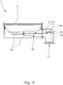
- FIG. 3 is shown a simplified sectional view of the sieve device shown in Fig. 1 seen through the line 2-2, where a filter guard in the form of a float 17 is in a passive or inactivated, first position.
- a bypass device constituted by a hinged plate 19 is releasably attached to a float arm 17' by means of an engagement element 21.
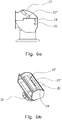
- the engagement element 21 is best seen in Figs. 6a and 6b .
- the plate 19 closes the passage toward the second outlet 11. Fluid being led into the second outlet 11 must therefore first pass through the secondary filter 13.
- the float 17 may be connected to a signal transmitter giving a signal or an alarm when the float 17 is lifted above a certain level by the drilling liquid. Thereby an operator may be warned that the filter is clogged. Action may then be taken in a controlled manner.
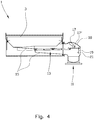
- the drill cuttings Due to the specific gravity of the drill cuttings a substantial portion of the drill cuttings may at least initially, sink to the secondary filter 13 while the drilling liquid is drained through the flow path provided by means of the plate 19 released from its engagement with the float arm 17' and thereby providing an opening for flow. If supply of drilling mud continues, drill cuttings will also gradually be led into the second outlet 11. It may therefore be advantageous if the second outlet 11 is in fluid communication with for example a not shown precipitation tank so that drill cuttings may be separated from the drilling liquid before the drilling liquid continues into the second outlet 11.
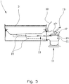
- a secondary filter 13 in the act of being removed from or led into the sieve device 1.
- a lid 18 being a part of a housing enclosing the float 17 and the plate 19 is shown in an open position.
- the secondary filter 13 is provided with vertical walls defining space. The advantage of said space is that it may limit the movement of the drill cuttings on the secondary filter 13.
- two filters whereof the one is arranged below the other, constitute the secondary filter 13.
- one of the two secondary filters may be removed from the sieve device and emptied while the other of the two secondary filters maintains the filtering of the untreated drilling mud.
- On minor damage to the filter cloth operation may be mainly maintained without any danger for untreated drill cuttings being mixed into the return liquid before it flows into the second outlet 11. This is done by regularly emptying each of the secondary filters 13. It is to be understood that more than two filters may also be placed one above the other.
- the filter guard is shown in the form of a float 17. It is however to be understood that the filter guard in an alternative, not shown embodiment, may be constituted by a weight arranged to be able to be influenced by the mass of drilling liquid and drill cuttings being carried by the secondary filter 13. On registering a mass exceeding a predetermined level, a signal may be given to a driving device arranged to be able to provide an alternative flow path for example of the kind explained in the above embodiment example. The weight may in addition be connected to an alarm.
- the filter guard may, in addition or as an alternative, be based on measuring a pressure differential across the secondary filter 13. On registering a pressure differential exceeding a predetermined level, a signal may be given to a driving device arranged to be able to provide an alternative flow path for example of a kind explained in the above embodiment example. Also in this case a signal to an alarm may be given.
- the embodiment example is directed to a sieve device including a rotating screening cloth
- the invention may also be used for sieve devices of the vibratory type having only one or more stationary screening cloths.
- the secondary filter is arranged separately from that part of the sieve device being directly connected to the displaced clump weight effecting the shaking movement in the vibratory separator.
- the secondary filter according to the present invention thus provides an improved control of the sieve device integrity at the same time as an operator is warned that the screening cloth may be damaged.
- the secondary filter will provide a possibility to take controlled actions.
- the secondary filter thus functions as an "auxiliary filter” or a "warning filter”.
Landscapes
- Engineering & Computer Science (AREA)
- Geology (AREA)
- Mining & Mineral Resources (AREA)
- Life Sciences & Earth Sciences (AREA)
- Chemical Kinetics & Catalysis (AREA)
- Chemical & Material Sciences (AREA)
- Physics & Mathematics (AREA)
- Fluid Mechanics (AREA)
- Environmental & Geological Engineering (AREA)
- Mechanical Engineering (AREA)
- General Life Sciences & Earth Sciences (AREA)
- Geochemistry & Mineralogy (AREA)
- Combined Means For Separation Of Solids (AREA)
- Filtration Of Liquid (AREA)
- Excavating Of Shafts Or Tunnels (AREA)
- Confectionery (AREA)
- Earth Drilling (AREA)
Claims (8)
- Siebvorrichtung (1) für unbehandelten Bauschlamm aufweisend Bohrflüssigkeit und Bohrspäne, welcher aus einem Bohrloch hochgeholt wurde, wobei die Siebvorrichtung (1) mit einer Filtervorrichtung (3) versehen ist, welche dazu eingerichtet ist, um einen Teil der Bohrflüssigkeit von den Bohrspänen zu trennen, und wobei die Siebvorrichtung (1) mit einem ersten Auslass, welcher dazu eingerichtet ist, die Bohrspäne, welche auf der Filtervorrichtung (3) zurückgehalten wurden, aufnehmen zu können, und mit einem zweiten Auslass (11), welcher dazu eingerichtet ist, Bohrflüssigkeit, welche durch die Filtervorrichtung (3) gelaufen ist und mittels eines Kanals (15) zu dem zweiten Auslass (11) geführt wurde, aufnehmen zu können, verbunden ist, wobei die Siebvorrichtung mit mindestens einem sekundären Filter (13) versehen ist, welcher dazu eingerichtet ist, um Bohrspäne von Bohrflüssigkeit trennen zu können, wobei der sekundäre Filter (13) auf solche Weise in dem besagten Kanal (15) angeordnet ist, dass Bohrflüssigkeit durch den sekundären Filter(13) und dann weiter zu besagtem zweiten Auslass (11) geleitet wird, dadurch gekennzeichnet, dass die Siebvorrichtung (1) zudem ausgestattet ist mit:- einem Filterschutz (17), welcher in Verbindung mit dem sekundären Filter (13) angeordnet ist; und- einer Umgehungsvorrichtung (19), welche mittels des Filterschutzes (17) angeordnet ist, um zur Übertragung von unbehandeltem Bohrschlamm, welcher auf dem sekundären Filter (13) zurückgehalten wird, in den besagten zweiten Auslass (11) für Bohrflüssigkeit, geöffnet werden zu können.
- Siebvorrichtung (1) nach Anspruch 1, wobei der Filterschutz (17) gesteuert wird durch eines oder einer Kombination von einem Gewicht von Material, welches auf dem sekundären Filter (13) zurückgehalten wird oder einem Volumen von Material, welches auf dem sekundären Filter (13) zurückgehalten wird.
- Siebvorrichtung (1) nach Anspruch 1, wobei mindestens ein Teil des sekundären Filters (13) innerhalb einer durch die Filtervorrichtung (3) bestimmten Grundfläche angeordnet ist.
- Siebvorrichtung (1) nach Anspruch 1, wobei die Siebvorrichtung (1) von dem Typ ist, bei dem die Filtervorrichtung (3) ein Filtertuch enthält, welches so angeordnet ist, dass es sich um zwei voneinander beabstandet positionierte Drehrollen (5) drehen kann.
- Siebvorrichtung (1) nach Anspruch 4, wobei der Filterschutz (17) gesteuert wird durch eines von oder eine Kombination aus:einer Druckdifferenz vor und hinter dem sekundären Filter;einem Gewicht von Material, welches auf dem sekundären Filter (13) zurückgehaltenen wird; odereinem Volumen von Material, welches auf dem sekundären Filter (13) zurückgehaltenen wird.
- Siebvorrichtung (1) nach Anspruch 1, wobei der sekundäre Filter (13) aus mindestens zwei Filtern gebildet wird, wobei der eine unter dem anderen angeordnet ist.
- Verfahren zur Kontrolle der Integrität einer Filtervorrichtung (3) in einer Siebvorrichtung (1), welche dazu eingerichtet ist, um einen Teil der Bohrflüssigkeit in einer unbehandelten Bohrschlamm von den Bohrspänen in der unbehandelten Bohrschlamm zu trennen,
wobei die Siebvorrichtung (1) mit einem ersten Auslass, welcher dazu eingerichtet ist, die Bohrspäne, welche auf der Filtervorrichtung (3) zurückgehalten wurden, aufnehmen zu können, und mit einem zweiten Auslass (11), welcher dazu eingerichtet ist, Bohrflüssigkeit, welche durch die Filtervorrichtung (3) läuft und mittels eines Kanals (15) zu dem zweiten Auslass (11) geführt wird, aufnehmen zu können, verbunden ist,
dadurch gekennzeichnet, dass das Verfahren zudem die folgenden Schritte umfasst:- Platzieren wenigstens einen sekundären Filters (13) in besagten Kanal (15);- Bemerken von unbehandelter Bohrspülung, welcher auf oder durch den sekundären Filter (13) zurückgehalten wird; und- wenn die Menge des unbehandelten Bohrschlamms, welcher auf oder durch den sekundären Filter (13) zurückgehalten wird, einen Grenzwert überschreitet, oder ein Flüssigkeitsstrom durch den sekundären Filter kleiner als ein Grenzwert wird, Öffnen einer Umgehungsvorrichtung (19) zur Übertragung von dem unbehandelten Bohrschlamm zwischen der vorgeschalteten Seite des sekundären Filters (13) und dem zweiten Auslass (11). - Verfahren nach Anspruch 7, wobei das Verfahren femer das Anordnen eines Niederschlagsbehälters in Verbindung mit dem zweiten Auslass (11) umfasst.
Applications Claiming Priority (2)
| Application Number | Priority Date | Filing Date | Title |
|---|---|---|---|
| NO20101011A NO332397B1 (no) | 2010-07-15 | 2010-07-15 | Siktinnretning for urenset boreslam og en framgangmate ved bruk av samme |
| PCT/NO2011/000185 WO2012008844A1 (en) | 2010-07-15 | 2011-06-27 | Sieve device for untreated drilling mud and a method of using same |
Publications (3)
| Publication Number | Publication Date |
|---|---|
| EP2593632A1 EP2593632A1 (de) | 2013-05-22 |
| EP2593632A4 EP2593632A4 (de) | 2017-12-20 |
| EP2593632B1 true EP2593632B1 (de) | 2018-10-17 |
Family
ID=45469657
Family Applications (1)
| Application Number | Title | Priority Date | Filing Date |
|---|---|---|---|
| EP11807109.1A Active EP2593632B1 (de) | 2010-07-15 | 2011-06-27 | Siebvorrichtung für unbehandelten bohrschlamm und verfahren zur verwendung davon |
Country Status (5)
| Country | Link |
|---|---|
| US (1) | US9399896B2 (de) |
| EP (1) | EP2593632B1 (de) |
| CA (1) | CA2804972C (de) |
| NO (1) | NO332397B1 (de) |
| WO (1) | WO2012008844A1 (de) |
Families Citing this family (6)
| Publication number | Priority date | Publication date | Assignee | Title |
|---|---|---|---|---|
| US9249646B2 (en) | 2011-11-16 | 2016-02-02 | Weatherford Technology Holdings, Llc | Managed pressure cementing |
| CN104612609A (zh) * | 2015-01-31 | 2015-05-13 | 成都科盛石油科技有限公司 | 基于筛分网滑道的石油钻井液分离筛 |
| CN104989300A (zh) * | 2015-06-17 | 2015-10-21 | 成都高普石油工程技术有限公司 | 一种净化石油钻井液的分离装置 |
| CN112122090A (zh) * | 2020-10-12 | 2020-12-25 | 濮阳市中原锐实达石油设备有限公司 | 一种用于钻井泥浆的固液气分离一体筛 |
| CN114295584B (zh) * | 2021-12-30 | 2023-08-04 | 中国地质大学(武汉) | 基于散射式红外浊度计的泥浆含砂量在线检测装置和方法 |
| CN114702162B (zh) * | 2022-04-11 | 2023-01-17 | 西安石油大学 | 一种环保型基于多级净化的钻井液集成处理系统 |
Family Cites Families (14)
| Publication number | Priority date | Publication date | Assignee | Title |
|---|---|---|---|---|
| US3464557A (en) * | 1966-12-12 | 1969-09-02 | Bowser Inc | Movable filter and magnetic sealing means |
| US3563255A (en) * | 1968-12-27 | 1971-02-16 | Royden Barnard Morris | Apparatus for collecting and washing well cuttings |
| US3849313A (en) * | 1972-11-30 | 1974-11-19 | Pullman Inc | Belt for a vacuum filter |
| US3911741A (en) * | 1973-01-16 | 1975-10-14 | Robert W Rochon | Pneumatic fluid weighing device |
| US3963605A (en) * | 1974-03-14 | 1976-06-15 | Phillips Petroleum Company | Coated shaker screen apparatus and method |
| US5454957A (en) * | 1993-04-19 | 1995-10-03 | Roff, Jr.; John W. | Closed loop system and method of processing cuttings |
| DK0825895T3 (da) | 1994-09-13 | 1999-08-23 | Rig Technology Ltd | Forbedringer for apparatur vedrørende vibrerende sigtning |
| US6530482B1 (en) * | 2000-04-26 | 2003-03-11 | Michael D. Wiseman | Tandem shale shaker |
| CA2322304C (en) * | 2000-10-04 | 2009-01-27 | Surface To Surface Inc. | Apparatus and method for recycling drilling slurry |
| US7198156B2 (en) | 2000-11-17 | 2007-04-03 | Varco I/P, Inc. | Dam basket for vibratory separators |
| NO326594B1 (no) | 2005-03-18 | 2009-01-19 | Cubility As | Siktapparat og fremgangsmate ved bruk av samme |
| NO322618B1 (no) * | 2005-04-20 | 2006-11-06 | 2K Tech As | Anordning og fremgangsmate for tilstandskontroll. |
| NO323519B1 (no) | 2005-06-30 | 2007-04-06 | Virdrill As | Sikt- og fluidseparasjonsapparat samt fremgangsmate ved bruk av samme. |
| US8556083B2 (en) | 2008-10-10 | 2013-10-15 | National Oilwell Varco L.P. | Shale shakers with selective series/parallel flow path conversion |
-
2010
- 2010-07-15 NO NO20101011A patent/NO332397B1/no unknown
-
2011
- 2011-06-27 WO PCT/NO2011/000185 patent/WO2012008844A1/en active Application Filing
- 2011-06-27 EP EP11807109.1A patent/EP2593632B1/de active Active
- 2011-06-27 US US13/809,241 patent/US9399896B2/en active Active
- 2011-06-27 CA CA2804972A patent/CA2804972C/en active Active
Non-Patent Citations (1)
| Title |
|---|
| None * |
Also Published As
| Publication number | Publication date |
|---|---|
| WO2012008844A1 (en) | 2012-01-19 |
| EP2593632A4 (de) | 2017-12-20 |
| CA2804972C (en) | 2018-09-11 |
| US20130112631A1 (en) | 2013-05-09 |
| US9399896B2 (en) | 2016-07-26 |
| CA2804972A1 (en) | 2012-01-19 |
| NO332397B1 (no) | 2012-09-10 |
| NO20101011A1 (no) | 2012-01-16 |
| EP2593632A1 (de) | 2013-05-22 |
Similar Documents
| Publication | Publication Date | Title |
|---|---|---|
| EP2593632B1 (de) | Siebvorrichtung für unbehandelten bohrschlamm und verfahren zur verwendung davon | |
| US9079222B2 (en) | Shale shaker | |
| US8695809B2 (en) | Return drilling fluid processing | |
| US8201693B2 (en) | Apparatus and method for separating solids from a solids laden liquid | |
| US9364777B2 (en) | Apparatus and method for separating solids from a solids laden drilling fluid | |
| US6530482B1 (en) | Tandem shale shaker | |
| JP4924954B2 (ja) | 振動分離機 | |
| US8869986B2 (en) | Screening methods and apparatus | |
| WO2008042646A1 (en) | Self-cleaning shaker | |
| US8807343B2 (en) | Screening method and apparatus | |
| NO319318B1 (no) | Separasjonssystem med kontinuerlig belte for boreslam | |
| CA2723992C (en) | Cuttings transfer system | |
| US10711545B2 (en) | Shale shaker with stair-stepped arrangements of screens and methods of using same, and methods of retrofitting shale shakers | |
| US20170001219A1 (en) | Sieving Apparatus And Method Of Using Same | |
| WO2020256921A1 (en) | Vibratory separators |
Legal Events
| Date | Code | Title | Description |
|---|---|---|---|
| PUAI | Public reference made under article 153(3) epc to a published international application that has entered the european phase |
Free format text: ORIGINAL CODE: 0009012 |
|
| 17P | Request for examination filed |
Effective date: 20130104 |
|
| AK | Designated contracting states |
Kind code of ref document: A1 Designated state(s): AL AT BE BG CH CY CZ DE DK EE ES FI FR GB GR HR HU IE IS IT LI LT LU LV MC MK MT NL NO PL PT RO RS SE SI SK SM TR |
|
| DAX | Request for extension of the european patent (deleted) | ||
| RAP1 | Party data changed (applicant data changed or rights of an application transferred) |
Owner name: CUBILITY AS |
|
| RA4 | Supplementary search report drawn up and despatched (corrected) |
Effective date: 20171116 |
|
| RIC1 | Information provided on ipc code assigned before grant |
Ipc: B01D 41/00 20060101ALI20171110BHEP Ipc: E21B 21/06 20060101AFI20171110BHEP |
|
| GRAP | Despatch of communication of intention to grant a patent |
Free format text: ORIGINAL CODE: EPIDOSNIGR1 |
|
| STAA | Information on the status of an ep patent application or granted ep patent |
Free format text: STATUS: GRANT OF PATENT IS INTENDED |
|
| INTG | Intention to grant announced |
Effective date: 20180625 |
|
| GRAS | Grant fee paid |
Free format text: ORIGINAL CODE: EPIDOSNIGR3 |
|
| GRAA | (expected) grant |
Free format text: ORIGINAL CODE: 0009210 |
|
| STAA | Information on the status of an ep patent application or granted ep patent |
Free format text: STATUS: THE PATENT HAS BEEN GRANTED |
|
| AK | Designated contracting states |
Kind code of ref document: B1 Designated state(s): AL AT BE BG CH CY CZ DE DK EE ES FI FR GB GR HR HU IE IS IT LI LT LU LV MC MK MT NL NO PL PT RO RS SE SI SK SM TR |
|
| REG | Reference to a national code |
Ref country code: GB Ref legal event code: FG4D |
|
| REG | Reference to a national code |
Ref country code: CH Ref legal event code: EP |
|
| REG | Reference to a national code |
Ref country code: IE Ref legal event code: FG4D |
|
| REG | Reference to a national code |
Ref country code: AT Ref legal event code: REF Ref document number: 1054248 Country of ref document: AT Kind code of ref document: T Effective date: 20181115 |
|
| REG | Reference to a national code |
Ref country code: DE Ref legal event code: R096 Ref document number: 602011053036 Country of ref document: DE |
|
| REG | Reference to a national code |
Ref country code: NL Ref legal event code: MP Effective date: 20181017 |
|
| REG | Reference to a national code |
Ref country code: LT Ref legal event code: MG4D |
|
| REG | Reference to a national code |
Ref country code: AT Ref legal event code: MK05 Ref document number: 1054248 Country of ref document: AT Kind code of ref document: T Effective date: 20181017 |
|
| REG | Reference to a national code |
Ref country code: NO Ref legal event code: T2 Effective date: 20181017 |
|
| PG25 | Lapsed in a contracting state [announced via postgrant information from national office to epo] |
Ref country code: NL Free format text: LAPSE BECAUSE OF FAILURE TO SUBMIT A TRANSLATION OF THE DESCRIPTION OR TO PAY THE FEE WITHIN THE PRESCRIBED TIME-LIMIT Effective date: 20181017 |
|
| PG25 | Lapsed in a contracting state [announced via postgrant information from national office to epo] |
Ref country code: FI Free format text: LAPSE BECAUSE OF FAILURE TO SUBMIT A TRANSLATION OF THE DESCRIPTION OR TO PAY THE FEE WITHIN THE PRESCRIBED TIME-LIMIT Effective date: 20181017 Ref country code: LT Free format text: LAPSE BECAUSE OF FAILURE TO SUBMIT A TRANSLATION OF THE DESCRIPTION OR TO PAY THE FEE WITHIN THE PRESCRIBED TIME-LIMIT Effective date: 20181017 Ref country code: PL Free format text: LAPSE BECAUSE OF FAILURE TO SUBMIT A TRANSLATION OF THE DESCRIPTION OR TO PAY THE FEE WITHIN THE PRESCRIBED TIME-LIMIT Effective date: 20181017 Ref country code: BG Free format text: LAPSE BECAUSE OF FAILURE TO SUBMIT A TRANSLATION OF THE DESCRIPTION OR TO PAY THE FEE WITHIN THE PRESCRIBED TIME-LIMIT Effective date: 20190117 Ref country code: AT Free format text: LAPSE BECAUSE OF FAILURE TO SUBMIT A TRANSLATION OF THE DESCRIPTION OR TO PAY THE FEE WITHIN THE PRESCRIBED TIME-LIMIT Effective date: 20181017 Ref country code: IS Free format text: LAPSE BECAUSE OF FAILURE TO SUBMIT A TRANSLATION OF THE DESCRIPTION OR TO PAY THE FEE WITHIN THE PRESCRIBED TIME-LIMIT Effective date: 20190217 Ref country code: ES Free format text: LAPSE BECAUSE OF FAILURE TO SUBMIT A TRANSLATION OF THE DESCRIPTION OR TO PAY THE FEE WITHIN THE PRESCRIBED TIME-LIMIT Effective date: 20181017 Ref country code: HR Free format text: LAPSE BECAUSE OF FAILURE TO SUBMIT A TRANSLATION OF THE DESCRIPTION OR TO PAY THE FEE WITHIN THE PRESCRIBED TIME-LIMIT Effective date: 20181017 Ref country code: LV Free format text: LAPSE BECAUSE OF FAILURE TO SUBMIT A TRANSLATION OF THE DESCRIPTION OR TO PAY THE FEE WITHIN THE PRESCRIBED TIME-LIMIT Effective date: 20181017 |
|
| PG25 | Lapsed in a contracting state [announced via postgrant information from national office to epo] |
Ref country code: AL Free format text: LAPSE BECAUSE OF FAILURE TO SUBMIT A TRANSLATION OF THE DESCRIPTION OR TO PAY THE FEE WITHIN THE PRESCRIBED TIME-LIMIT Effective date: 20181017 Ref country code: SE Free format text: LAPSE BECAUSE OF FAILURE TO SUBMIT A TRANSLATION OF THE DESCRIPTION OR TO PAY THE FEE WITHIN THE PRESCRIBED TIME-LIMIT Effective date: 20181017 Ref country code: RS Free format text: LAPSE BECAUSE OF FAILURE TO SUBMIT A TRANSLATION OF THE DESCRIPTION OR TO PAY THE FEE WITHIN THE PRESCRIBED TIME-LIMIT Effective date: 20181017 Ref country code: GR Free format text: LAPSE BECAUSE OF FAILURE TO SUBMIT A TRANSLATION OF THE DESCRIPTION OR TO PAY THE FEE WITHIN THE PRESCRIBED TIME-LIMIT Effective date: 20190118 Ref country code: PT Free format text: LAPSE BECAUSE OF FAILURE TO SUBMIT A TRANSLATION OF THE DESCRIPTION OR TO PAY THE FEE WITHIN THE PRESCRIBED TIME-LIMIT Effective date: 20190217 |
|
| REG | Reference to a national code |
Ref country code: DE Ref legal event code: R097 Ref document number: 602011053036 Country of ref document: DE |
|
| PG25 | Lapsed in a contracting state [announced via postgrant information from national office to epo] |
Ref country code: IT Free format text: LAPSE BECAUSE OF FAILURE TO SUBMIT A TRANSLATION OF THE DESCRIPTION OR TO PAY THE FEE WITHIN THE PRESCRIBED TIME-LIMIT Effective date: 20181017 Ref country code: DK Free format text: LAPSE BECAUSE OF FAILURE TO SUBMIT A TRANSLATION OF THE DESCRIPTION OR TO PAY THE FEE WITHIN THE PRESCRIBED TIME-LIMIT Effective date: 20181017 Ref country code: CZ Free format text: LAPSE BECAUSE OF FAILURE TO SUBMIT A TRANSLATION OF THE DESCRIPTION OR TO PAY THE FEE WITHIN THE PRESCRIBED TIME-LIMIT Effective date: 20181017 |
|
| PLBE | No opposition filed within time limit |
Free format text: ORIGINAL CODE: 0009261 |
|
| STAA | Information on the status of an ep patent application or granted ep patent |
Free format text: STATUS: NO OPPOSITION FILED WITHIN TIME LIMIT |
|
| PG25 | Lapsed in a contracting state [announced via postgrant information from national office to epo] |
Ref country code: EE Free format text: LAPSE BECAUSE OF FAILURE TO SUBMIT A TRANSLATION OF THE DESCRIPTION OR TO PAY THE FEE WITHIN THE PRESCRIBED TIME-LIMIT Effective date: 20181017 Ref country code: RO Free format text: LAPSE BECAUSE OF FAILURE TO SUBMIT A TRANSLATION OF THE DESCRIPTION OR TO PAY THE FEE WITHIN THE PRESCRIBED TIME-LIMIT Effective date: 20181017 Ref country code: SK Free format text: LAPSE BECAUSE OF FAILURE TO SUBMIT A TRANSLATION OF THE DESCRIPTION OR TO PAY THE FEE WITHIN THE PRESCRIBED TIME-LIMIT Effective date: 20181017 Ref country code: SM Free format text: LAPSE BECAUSE OF FAILURE TO SUBMIT A TRANSLATION OF THE DESCRIPTION OR TO PAY THE FEE WITHIN THE PRESCRIBED TIME-LIMIT Effective date: 20181017 |
|
| 26N | No opposition filed |
Effective date: 20190718 |
|
| PG25 | Lapsed in a contracting state [announced via postgrant information from national office to epo] |
Ref country code: SI Free format text: LAPSE BECAUSE OF FAILURE TO SUBMIT A TRANSLATION OF THE DESCRIPTION OR TO PAY THE FEE WITHIN THE PRESCRIBED TIME-LIMIT Effective date: 20181017 |
|
| REG | Reference to a national code |
Ref country code: DE Ref legal event code: R119 Ref document number: 602011053036 Country of ref document: DE |
|
| PG25 | Lapsed in a contracting state [announced via postgrant information from national office to epo] |
Ref country code: MC Free format text: LAPSE BECAUSE OF FAILURE TO SUBMIT A TRANSLATION OF THE DESCRIPTION OR TO PAY THE FEE WITHIN THE PRESCRIBED TIME-LIMIT Effective date: 20181017 |
|
| REG | Reference to a national code |
Ref country code: CH Ref legal event code: PL |
|
| REG | Reference to a national code |
Ref country code: BE Ref legal event code: MM Effective date: 20190630 |
|
| PG25 | Lapsed in a contracting state [announced via postgrant information from national office to epo] |
Ref country code: TR Free format text: LAPSE BECAUSE OF FAILURE TO SUBMIT A TRANSLATION OF THE DESCRIPTION OR TO PAY THE FEE WITHIN THE PRESCRIBED TIME-LIMIT Effective date: 20181017 |
|
| PG25 | Lapsed in a contracting state [announced via postgrant information from national office to epo] |
Ref country code: DE Free format text: LAPSE BECAUSE OF NON-PAYMENT OF DUE FEES Effective date: 20200101 Ref country code: IE Free format text: LAPSE BECAUSE OF NON-PAYMENT OF DUE FEES Effective date: 20190627 |
|
| PG25 | Lapsed in a contracting state [announced via postgrant information from national office to epo] |
Ref country code: CH Free format text: LAPSE BECAUSE OF NON-PAYMENT OF DUE FEES Effective date: 20190630 Ref country code: LI Free format text: LAPSE BECAUSE OF NON-PAYMENT OF DUE FEES Effective date: 20190630 Ref country code: BE Free format text: LAPSE BECAUSE OF NON-PAYMENT OF DUE FEES Effective date: 20190630 Ref country code: LU Free format text: LAPSE BECAUSE OF NON-PAYMENT OF DUE FEES Effective date: 20190627 |
|
| PG25 | Lapsed in a contracting state [announced via postgrant information from national office to epo] |
Ref country code: FR Free format text: LAPSE BECAUSE OF NON-PAYMENT OF DUE FEES Effective date: 20190630 |
|
| PG25 | Lapsed in a contracting state [announced via postgrant information from national office to epo] |
Ref country code: CY Free format text: LAPSE BECAUSE OF FAILURE TO SUBMIT A TRANSLATION OF THE DESCRIPTION OR TO PAY THE FEE WITHIN THE PRESCRIBED TIME-LIMIT Effective date: 20181017 |
|
| PG25 | Lapsed in a contracting state [announced via postgrant information from national office to epo] |
Ref country code: HU Free format text: LAPSE BECAUSE OF FAILURE TO SUBMIT A TRANSLATION OF THE DESCRIPTION OR TO PAY THE FEE WITHIN THE PRESCRIBED TIME-LIMIT; INVALID AB INITIO Effective date: 20110627 Ref country code: MT Free format text: LAPSE BECAUSE OF FAILURE TO SUBMIT A TRANSLATION OF THE DESCRIPTION OR TO PAY THE FEE WITHIN THE PRESCRIBED TIME-LIMIT Effective date: 20181017 |
|
| PG25 | Lapsed in a contracting state [announced via postgrant information from national office to epo] |
Ref country code: MK Free format text: LAPSE BECAUSE OF FAILURE TO SUBMIT A TRANSLATION OF THE DESCRIPTION OR TO PAY THE FEE WITHIN THE PRESCRIBED TIME-LIMIT Effective date: 20181017 |
|
| PGFP | Annual fee paid to national office [announced via postgrant information from national office to epo] |
Ref country code: NO Payment date: 20230606 Year of fee payment: 13 |
|
| PGFP | Annual fee paid to national office [announced via postgrant information from national office to epo] |
Ref country code: GB Payment date: 20230621 Year of fee payment: 13 |