EP2593632B1 - Sieve device for untreated drilling mud and a method of using same - Google Patents
Sieve device for untreated drilling mud and a method of using same Download PDFInfo
- Publication number
- EP2593632B1 EP2593632B1 EP11807109.1A EP11807109A EP2593632B1 EP 2593632 B1 EP2593632 B1 EP 2593632B1 EP 11807109 A EP11807109 A EP 11807109A EP 2593632 B1 EP2593632 B1 EP 2593632B1
- Authority
- EP
- European Patent Office
- Prior art keywords
- filter
- secondary filter
- outlet
- sieve device
- held back
- Prior art date
- Legal status (The legal status is an assumption and is not a legal conclusion. Google has not performed a legal analysis and makes no representation as to the accuracy of the status listed.)
- Active
Links
Images


Classifications
-
- E—FIXED CONSTRUCTIONS
- E21—EARTH DRILLING; MINING
- E21B—EARTH DRILLING, e.g. DEEP DRILLING; OBTAINING OIL, GAS, WATER, SOLUBLE OR MELTABLE MATERIALS OR A SLURRY OF MINERALS FROM WELLS
- E21B21/00—Methods or apparatus for flushing boreholes, e.g. by use of exhaust air from motor
- E21B21/06—Arrangements for treating drilling fluids outside the borehole
- E21B21/063—Arrangements for treating drilling fluids outside the borehole by separating components
- E21B21/065—Separating solids from drilling fluids
-
- B—PERFORMING OPERATIONS; TRANSPORTING
- B01—PHYSICAL OR CHEMICAL PROCESSES OR APPARATUS IN GENERAL
- B01D—SEPARATION
- B01D41/00—Regeneration of the filtering material or filter elements outside the filter for liquid or gaseous fluids
-
- B—PERFORMING OPERATIONS; TRANSPORTING
- B01—PHYSICAL OR CHEMICAL PROCESSES OR APPARATUS IN GENERAL
- B01D—SEPARATION
- B01D2311/00—Details relating to membrane separation process operations and control
- B01D2311/14—Pressure control
-
- B—PERFORMING OPERATIONS; TRANSPORTING
- B01—PHYSICAL OR CHEMICAL PROCESSES OR APPARATUS IN GENERAL
- B01D—SEPARATION
- B01D2321/00—Details relating to membrane cleaning, regeneration, sterilization or to the prevention of fouling
- B01D2321/40—Automatic control of cleaning processes
-
- B—PERFORMING OPERATIONS; TRANSPORTING
- B01—PHYSICAL OR CHEMICAL PROCESSES OR APPARATUS IN GENERAL
- B01D—SEPARATION
- B01D39/00—Filtering material for liquid or gaseous fluids
- B01D39/08—Filter cloth, i.e. woven, knitted or interlaced material
-
- B—PERFORMING OPERATIONS; TRANSPORTING
- B01—PHYSICAL OR CHEMICAL PROCESSES OR APPARATUS IN GENERAL
- B01D—SEPARATION
- B01D46/00—Filters or filtering processes specially modified for separating dispersed particles from gases or vapours
- B01D46/56—Filters or filtering processes specially modified for separating dispersed particles from gases or vapours with multiple filtering elements, characterised by their mutual disposition
- B01D46/62—Filters or filtering processes specially modified for separating dispersed particles from gases or vapours with multiple filtering elements, characterised by their mutual disposition connected in series
-
- B—PERFORMING OPERATIONS; TRANSPORTING
- B01—PHYSICAL OR CHEMICAL PROCESSES OR APPARATUS IN GENERAL
- B01D—SEPARATION
- B01D46/00—Filters or filtering processes specially modified for separating dispersed particles from gases or vapours
- B01D46/66—Regeneration of the filtering material or filter elements inside the filter
-
- E—FIXED CONSTRUCTIONS
- E21—EARTH DRILLING; MINING
- E21B—EARTH DRILLING, e.g. DEEP DRILLING; OBTAINING OIL, GAS, WATER, SOLUBLE OR MELTABLE MATERIALS OR A SLURRY OF MINERALS FROM WELLS
- E21B21/00—Methods or apparatus for flushing boreholes, e.g. by use of exhaust air from motor
- E21B21/06—Arrangements for treating drilling fluids outside the borehole
Definitions
- the present invention relates to a sieve device. More particularly it concerns a sieve device for untreated drilling mud brought up from a well, and a method for using the sieve device, where the sieve device is provided with a filter device arranged to separate a share of the drilling liquid from the drill cuttings, and where the sieve device is connected to a first outlet arranged to be able to receive the drill cuttings held back on the filter device, and a second outlet arranged to be able to receive the drilling liquid which has been flowing through the filter device and has been directed to the second outlet through a channel.
- Drilling of wells in the oil and gas industry brings large quantities of untreated drilling mud out of the well and up to the earth surface or up to an offshore drilling rig.
- the untreated drilling mud contains fragments of drilled earth formations and drilling liquid or drilling mud and also any other fluids flowing into the well from the formation surrounding the well.
- the drilling liquid is circulated into the well.
- the drilled earth formations are termed drill cuttings.
- drill cuttings is in this document meant solid material exceeding a predetermined particle size decided by the mesh size of the filter device.
- a person skilled in the art will be familiar with the drilling liquid having several functions, among which are lubricating and cooling of the drill bit used in the drilling operation, carrying the drill cuttings out of the well bore, and being a weight agent for well control.
- the drilling liquid may be very expensive. For this reason, among others, there is a desire to recycle the drilling liquid being circulated out from the well together with the drill cuttings.
- sieve devices in the art known as "shale shakers" is common. These are large screening machines including one or more filter devices in the form of clamped screen cloths being vibrated by means of, as an example, one or more displaced clump weights.
- the present applicant has developed and described in Norwegian Patent N0323519 a sieving apparatus for screening and separation of fluid from a material containing fractions of a solid and a fluid, the material being placed on a topside of the at least one screening element including an endless screening cloth arranged to be moved about at least two mutually spaced apart turning rollers, the apparatus including at least one suction nozzle directed up against an underside of the endless screening cloth.
- the screening cloth thus rotates about two spaced apart turning rolls and the intended separation is provided by means of airflow instead of vibrating a stationary sieve by means of displaced clump weights.
- the apparatus is sold under the trademark "MudCube®".
- the screening cloths are exposed to a considerable wear and they will be worn to pieces if they are not replaced within a given period of use.
- the wear is particularly large for a screening cloth used in the above vibratory screening apparatus or shale shaker.
- the drilling liquid to be reused in the well is also called return liquid in the trade.
- the shale shaker screening cloth will normally be covered by untreated drilling mud supplied to the screening cloth. Thus it has turned out to be very difficult to detect defects in the screening cloth prior to sampling of the return liquid. Such samples are taken at set intervals by a so-called "Mud-logger". By the very fact that sampling is not continuous, solid particles of a size exceeding the screen mesh width may for a certain period of time be returned uncontrolled to the well.
- the applicant has earlier arranged an additional stationary filter in connection with the MudCube®.
- a filter guard will cause the supply of untreated drilling mud to the MudCube® to be stopped such that it is not flooded by untreated drilling mud.
- the object of the invention is to remedy or reduce at least one of the disadvantages of the prior art, or at least to provide a useful alternative to the prior art.
- a sieve device for untreated drilling mud containing drilling fluid and drill cuttings being brought up from a well, where the sieve device is provided with a filter device arranged to separate a share of the drilling liquid from the drill cuttings, and where the sieve device is connected to a first outlet arranged to be able to receive the drill cuttings held back on the filter device, and a second outlet arranged to be able to receive the drilling liquid flowing through the filter device and being directed to the second outlet via a channel, where the sieve device is further provided with:
- the filter guard may be arranged to give a signal to for example an operator before the bypass arrangement is opened as a consequence of held back untreated drilling mud on the secondary filter.
- An operator may thereby in a controlled manner be able to make a decision about stopping the supply of untreated drilling mud to the sieve device by, for example, rerouting the supply to another sieve device, or if untreated drilling mud and not only drilling liquid shall be allowed to flow into the return liquid.
- the signal from the filter guard may for example be initiated as a consequence of weight and/or volume of the mass being held back on the secondary filter.
- underpressure is used to suck fluids through the rotating filter device.
- the filter guard may, as an alternative or addition to said filter guard based on weight and/or volume, be based on monitoring of a pressure differential between an upstream and a downstream side of the secondary filter. Such monitoring has turned out to be particularly useful in giving an early warning about the secondary filter filling up with untreated drilling mud.
- the secondary filter may have a mesh width corresponding to the mesh width of the filter device.
- the secondary filter will thereby hold back solid particles having a size exceeding the mesh width of the filter device.
- the secondary filter may have a mesh width somewhat larger, for example 25% larger, than the mesh width of the filter device.
- the effect of this is that the filter may let some particles through which should have been held back by the filter device, but where the particles are not of such a size that they are able to create problems for use of the return liquid, as long as they are supplied in limited amounts.
- By use of such a larger mesh width it will take somewhat longer for the secondary filter to get clogged.
- Position reports such as “over” and “under” refer to positions relative to the Figures and to positions relevant in the usage positions of the apparatus.
- the reference numeral 1 indicates a sieve device including a filter device in the form of a filter cloth 3.
- the filter cloth 3 in Fig. 1 is only indicated by hachure in three places, but it is to be understood that the filter cloth 3 extends over turning rollers 5 arranged at each end portion of the sieve device 1.
- the turning rollers 5 are in Fig. 1 only visible in one of the end portions of the sieve device 1.
- the turning rollers 5 rotate and bring along the filter cloth 3. Between the turning rollers 5 the filter cloth 3 is carried glidingly against five longitudinal supporting elements 7.
- Untreated drilling mud including drilling liquid and solid particles in the form of drill cuttings are led from a supply portion 9 and onto the filter cloth 3.
- the drilling liquid may also contain fluids that may flow into the well from the surrounding formations.
- the sieve device 1 shown in the Figures is a development of a sieve device described in said Norwegian Patent NO323519 by the applicant and in the publication WO 2007/004889 .
- the publications describe, as mentioned above, an apparatus of the kind that separates a share of the drilling liquid from the drill cuttings by means of an airflow directed through the cloth in such a way that the airflow directs a considerable share of the liquid fraction of the contaminated drilling mud through the filter cloth 3, while drill cuttings larger than the mesh width of the filter cloth 3, are withheld and brought to a first outlet (not shown) located in an end portion at a turning roller 5.
- the airflow is provided by means of an underpressure-generating device (not shown) in fluid communication with a second outlet 11.
- a secondary filter 13 is arranged in connection with a chute or channel 15 leading drilling liquid having passed the filter cloth 3 further on to the second outlet 11.
- the secondary filter 13 will not take up further space in for example a drilling rig.
- the secondary filter 13 does not occupy further area or "footprint" than what is already occupied by the sieve device 1.
- the secondary filter 13 may be placed wholly or partly separate from the sieve device 1. As long as the integrity of the filter cloth 3 is intact, the secondary filter 13 will only receive drilling liquid.
- the secondary filter 13 has preferably a mesh size at least as large as the mesh size of the filter cloth 3.
- the drilling liquid will thus also pass through the secondary filter 13 and flow on, as return liquid, in the channel 15 and out through the second outlet 11. If damage occurs in the filter cloth 3, such as a hole or a tear, the filter cloth 3 will also let through drill cuttings of a size exceeding the filter cloth's 3 mesh size. These drill cuttings will, together with the drilling liquid, be led over the secondary filter 13.
- the secondary filter 13 will hold back drill cuttings of a size exceeding the secondary filter 13 mesh size. Drill cuttings will thus gradually fill up the secondary filter 13.
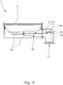
- FIG. 3 is shown a simplified sectional view of the sieve device shown in Fig. 1 seen through the line 2-2, where a filter guard in the form of a float 17 is in a passive or inactivated, first position.
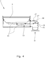
- a bypass device constituted by a hinged plate 19 is releasably attached to a float arm 17' by means of an engagement element 21.
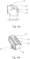
- the engagement element 21 is best seen in Figs. 6a and 6b .
- the plate 19 closes the passage toward the second outlet 11. Fluid being led into the second outlet 11 must therefore first pass through the secondary filter 13.
- the float 17 may be connected to a signal transmitter giving a signal or an alarm when the float 17 is lifted above a certain level by the drilling liquid. Thereby an operator may be warned that the filter is clogged. Action may then be taken in a controlled manner.
- the drill cuttings Due to the specific gravity of the drill cuttings a substantial portion of the drill cuttings may at least initially, sink to the secondary filter 13 while the drilling liquid is drained through the flow path provided by means of the plate 19 released from its engagement with the float arm 17' and thereby providing an opening for flow. If supply of drilling mud continues, drill cuttings will also gradually be led into the second outlet 11. It may therefore be advantageous if the second outlet 11 is in fluid communication with for example a not shown precipitation tank so that drill cuttings may be separated from the drilling liquid before the drilling liquid continues into the second outlet 11.
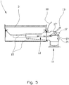
- a secondary filter 13 in the act of being removed from or led into the sieve device 1.
- a lid 18 being a part of a housing enclosing the float 17 and the plate 19 is shown in an open position.
- the secondary filter 13 is provided with vertical walls defining space. The advantage of said space is that it may limit the movement of the drill cuttings on the secondary filter 13.
- two filters whereof the one is arranged below the other, constitute the secondary filter 13.
- one of the two secondary filters may be removed from the sieve device and emptied while the other of the two secondary filters maintains the filtering of the untreated drilling mud.
- On minor damage to the filter cloth operation may be mainly maintained without any danger for untreated drill cuttings being mixed into the return liquid before it flows into the second outlet 11. This is done by regularly emptying each of the secondary filters 13. It is to be understood that more than two filters may also be placed one above the other.
- the filter guard is shown in the form of a float 17. It is however to be understood that the filter guard in an alternative, not shown embodiment, may be constituted by a weight arranged to be able to be influenced by the mass of drilling liquid and drill cuttings being carried by the secondary filter 13. On registering a mass exceeding a predetermined level, a signal may be given to a driving device arranged to be able to provide an alternative flow path for example of the kind explained in the above embodiment example. The weight may in addition be connected to an alarm.
- the filter guard may, in addition or as an alternative, be based on measuring a pressure differential across the secondary filter 13. On registering a pressure differential exceeding a predetermined level, a signal may be given to a driving device arranged to be able to provide an alternative flow path for example of a kind explained in the above embodiment example. Also in this case a signal to an alarm may be given.
- the embodiment example is directed to a sieve device including a rotating screening cloth
- the invention may also be used for sieve devices of the vibratory type having only one or more stationary screening cloths.
- the secondary filter is arranged separately from that part of the sieve device being directly connected to the displaced clump weight effecting the shaking movement in the vibratory separator.
- the secondary filter according to the present invention thus provides an improved control of the sieve device integrity at the same time as an operator is warned that the screening cloth may be damaged.
- the secondary filter will provide a possibility to take controlled actions.
- the secondary filter thus functions as an "auxiliary filter” or a "warning filter”.
Description
- The present invention relates to a sieve device. More particularly it concerns a sieve device for untreated drilling mud brought up from a well, and a method for using the sieve device, where the sieve device is provided with a filter device arranged to separate a share of the drilling liquid from the drill cuttings, and where the sieve device is connected to a first outlet arranged to be able to receive the drill cuttings held back on the filter device, and a second outlet arranged to be able to receive the drilling liquid which has been flowing through the filter device and has been directed to the second outlet through a channel.
- Drilling of wells in the oil and gas industry brings large quantities of untreated drilling mud out of the well and up to the earth surface or up to an offshore drilling rig. The untreated drilling mud contains fragments of drilled earth formations and drilling liquid or drilling mud and also any other fluids flowing into the well from the formation surrounding the well. The drilling liquid is circulated into the well. The drilled earth formations are termed drill cuttings. By drill cuttings is in this document meant solid material exceeding a predetermined particle size decided by the mesh size of the filter device.
- A person skilled in the art will be familiar with the drilling liquid having several functions, among which are lubricating and cooling of the drill bit used in the drilling operation, carrying the drill cuttings out of the well bore, and being a weight agent for well control.
- The drilling liquid may be very expensive. For this reason, among others, there is a desire to recycle the drilling liquid being circulated out from the well together with the drill cuttings. To separate valuable drilling liquid from the drill cuttings, the use of sieve devices in the art known as "shale shakers" is common. These are large screening machines including one or more filter devices in the form of clamped screen cloths being vibrated by means of, as an example, one or more displaced clump weights.
- The present applicant has developed and described in Norwegian Patent
N0323519 - By use of the screening apparatuses the screening cloths are exposed to a considerable wear and they will be worn to pieces if they are not replaced within a given period of use.
- The wear is particularly large for a screening cloth used in the above vibratory screening apparatus or shale shaker.
- When a screening cloth is worn to pieces, for example by a hole appearing in the screening cloth, solid particles otherwise being held back by the screening cloth, will stay mixed with the drilling liquid to be reused in the well. The drilling liquid to be reused in the well is also called return liquid in the trade.
- In use the shale shaker screening cloth will normally be covered by untreated drilling mud supplied to the screening cloth. Thus it has turned out to be very difficult to detect defects in the screening cloth prior to sampling of the return liquid. Such samples are taken at set intervals by a so-called "Mud-logger". By the very fact that sampling is not continuous, solid particles of a size exceeding the screen mesh width may for a certain period of time be returned uncontrolled to the well.
- To be able to detect defects in the rotating screening cloth in the MudCube®, the applicant has earlier arranged an additional stationary filter in connection with the MudCube®. When the filter is clogged by material passing the rotating screening cloth as a consequence of damage to this, a filter guard will cause the supply of untreated drilling mud to the MudCube® to be stopped such that it is not flooded by untreated drilling mud.
- Even if the above explained additional stationary filter prevents untreated drilling mud from being conveyed to the return liquid, an automatic stop of supply to the screening device may create problems for the process upstream of the screening device.
- Further background technology is known from the publication
US 2010/0809652 describing a sieve device having at least two filters with a system for controlling inflow of drilling fluid to each filter. - From the
publication WO 96/08301 - From the publication
WO 2006/092634 is known to control fluid level on the filter in each section and to keep the weight of fluid on the filter under control such that a vibration mechanism gets an even loading. - The object of the invention is to remedy or reduce at least one of the disadvantages of the prior art, or at least to provide a useful alternative to the prior art.
- The object is achieved by the features disclosed in the below description and in the subsequent claims.
- According to a first aspect of the present invention there is provided a sieve device for untreated drilling mud containing drilling fluid and drill cuttings being brought up from a well, where the sieve device is provided with a filter device arranged to separate a share of the drilling liquid from the drill cuttings, and where the sieve device is connected to a first outlet arranged to be able to receive the drill cuttings held back on the filter device, and a second outlet arranged to be able to receive the drilling liquid flowing through the filter device and being directed to the second outlet via a channel, where the sieve device is further provided with:
- at least one secondary filter arranged to be able to separate drill cuttings from drilling liquid, where the secondary filter is arranged in said channel in such a way that drilling liquid is lead through the filter and on to said second outlet;
- a filter guard arranged in connection with the secondary filter; and
- a bypass arrangement which by means of the filter guard is arranged to be able to open for communication of untreated drilling mud withheld on/by the secondary filter, into said second outlet for drilling liquid.
- By arranging for bypass of untreated drilling mud intercepted by the secondary filter, the process upstream of the sieve device will not be affected by breakage or damages to the filter device.
- The filter guard may be arranged to give a signal to for example an operator before the bypass arrangement is opened as a consequence of held back untreated drilling mud on the secondary filter. An operator may thereby in a controlled manner be able to make a decision about stopping the supply of untreated drilling mud to the sieve device by, for example, rerouting the supply to another sieve device, or if untreated drilling mud and not only drilling liquid shall be allowed to flow into the return liquid.
- The signal from the filter guard may for example be initiated as a consequence of weight and/or volume of the mass being held back on the secondary filter.
- In one variation of the sieve device of the present applicant, underpressure is used to suck fluids through the rotating filter device. By using such suction the filter guard may, as an alternative or addition to said filter guard based on weight and/or volume, be based on monitoring of a pressure differential between an upstream and a downstream side of the secondary filter. Such monitoring has turned out to be particularly useful in giving an early warning about the secondary filter filling up with untreated drilling mud.
- The secondary filter may have a mesh width corresponding to the mesh width of the filter device. The secondary filter will thereby hold back solid particles having a size exceeding the mesh width of the filter device.
- In an alternative embodiment the secondary filter may have a mesh width somewhat larger, for example 25% larger, than the mesh width of the filter device. The effect of this is that the filter may let some particles through which should have been held back by the filter device, but where the particles are not of such a size that they are able to create problems for use of the return liquid, as long as they are supplied in limited amounts. By use of such a larger mesh width it will take somewhat longer for the secondary filter to get clogged.
- In a second aspect of the invention there is provided a method to have control of the integrity of a filter device in a sieve device arranged to separate a share of a drilling liquid in an untreated drilling mud from drill cuttings in the untreated drilling mud, and where the sieve device is connected to a first outlet arranged to be able to receive the drill cuttings being held back on the filter device, and a second outlet arranged to be able to receive the drilling liquid flowing through the filter device and being directed to the second outlet via a channel, where the method further includes the steps of:
- placing at least one secondary filter in said channel;
- registering untreated drilling mud being held back on or by the secondary filter; and
- when the quantity of untreated drilling mud being held back on or by the secondary filter exceeds a limit value, or fluid flow through the secondary filter becomes less than a limit value, opening a bypass device (19) for communication of the untreated drilling mud between an upstream side of the secondary filter and the second outlet.
-
Fig. 1 shows a top view of a sieve device, where the sieve device is of the kind being constituted by a rotating screening cloth; -
Fig. 2 shows a perspective view of a portion of the sieve device inFig. 1 seen through the section 2-2 obliquely from above, but where the screening cloth is not shown; -
Fig. 3 shows a sectional view of the sieve device inFig. 1 seen through the line 2-2, where the sieve device is provided with a secondary filter and a filter guard in a closed or inactive position; -
Fig. 4 shows the sieve device ofFig. 3 , but where the filter guard is in an open or activated position and where a bypass arrangement is opened for communication between an upstream side of the secondary filter and an outlet for drilling liquid; -
Fig. 5 shows the sieve device ofFig. 4 , but where the filter guard is deactivated and where a portion of the secondary filter is in the process of being removed from or installed in the sieve device; -
Fig. 6a shows to a larger scale a side view of the filter guard and the bypass arrangement inFig. 3 ; and -
Fig. 6b shows the filter guard and the bypass arrangement inFig. 6a in perspective. - The Figures are only to be regarded as principle sketches where only elements important for the understanding of the present invention are shown. Moreover, only elements discussed in the following description are indicated by reference numerals.
- Position reports such as "over" and "under" refer to positions relative to the Figures and to positions relevant in the usage positions of the apparatus.
- In the Figures the
reference numeral 1 indicates a sieve device including a filter device in the form of afilter cloth 3. For the sake of clarity thefilter cloth 3 inFig. 1 is only indicated by hachure in three places, but it is to be understood that thefilter cloth 3 extends over turningrollers 5 arranged at each end portion of thesieve device 1. The turningrollers 5 are inFig. 1 only visible in one of the end portions of thesieve device 1. - In use the turning
rollers 5 rotate and bring along thefilter cloth 3. Between the turningrollers 5 thefilter cloth 3 is carried glidingly against five longitudinal supportingelements 7. - Untreated drilling mud including drilling liquid and solid particles in the form of drill cuttings, are led from a
supply portion 9 and onto thefilter cloth 3. The drilling liquid may also contain fluids that may flow into the well from the surrounding formations. - The
sieve device 1 shown in the Figures is a development of a sieve device described in said Norwegian PatentNO323519 WO 2007/004889 . The publications describe, as mentioned above, an apparatus of the kind that separates a share of the drilling liquid from the drill cuttings by means of an airflow directed through the cloth in such a way that the airflow directs a considerable share of the liquid fraction of the contaminated drilling mud through thefilter cloth 3, while drill cuttings larger than the mesh width of thefilter cloth 3, are withheld and brought to a first outlet (not shown) located in an end portion at a turningroller 5. The airflow is provided by means of an underpressure-generating device (not shown) in fluid communication with asecond outlet 11.
Asecondary filter 13 is arranged in connection with a chute orchannel 15 leading drilling liquid having passed thefilter cloth 3 further on to thesecond outlet 11.
By placing thesecondary filter 13 integrated in thechannel 15 as shown inFig. 2 , thesecondary filter 13 will not take up further space in for example a drilling rig. Thus thesecondary filter 13 does not occupy further area or "footprint" than what is already occupied by thesieve device 1. It is however to be understood that in alternative embodiments thesecondary filter 13 may be placed wholly or partly separate from thesieve device 1.
As long as the integrity of thefilter cloth 3 is intact, thesecondary filter 13 will only receive drilling liquid. Thesecondary filter 13 has preferably a mesh size at least as large as the mesh size of thefilter cloth 3. The drilling liquid will thus also pass through thesecondary filter 13 and flow on, as return liquid, in thechannel 15 and out through thesecond outlet 11.
If damage occurs in thefilter cloth 3, such as a hole or a tear, thefilter cloth 3 will also let through drill cuttings of a size exceeding the filter cloth's 3 mesh size. These drill cuttings will, together with the drilling liquid, be led over thesecondary filter 13. - The
secondary filter 13 will hold back drill cuttings of a size exceeding thesecondary filter 13 mesh size. Drill cuttings will thus gradually fill up thesecondary filter 13. - In
Fig. 3 is shown a simplified sectional view of the sieve device shown inFig. 1 seen through the line 2-2, where a filter guard in the form of afloat 17 is in a passive or inactivated, first position. A bypass device constituted by a hingedplate 19 is releasably attached to a float arm 17' by means of anengagement element 21. Theengagement element 21 is best seen inFigs. 6a and 6b . As long as theplate 19 is in engagement with the float arm 17', theplate 19 closes the passage toward thesecond outlet 11. Fluid being led into thesecond outlet 11 must therefore first pass through thesecondary filter 13. - The same is shown in
Fig. 4 as inFig. 3 , but thesecondary filter 13 has been clogged by drill cuttings to such an extent that drilling liquid is also being held back on thesecondary filter 13. Thefloat 17 is lifted up, by the drilling liquid, from the first position shown inFig. 3 by the drilling liquid to a second, upright position as shown inFig. 4 . Moving from the first position to the second position, theengagement element 21 is freed from its engagement with the float arm 17', and theplate 19 being supported in a not shown hinge device, opens for a flow path between an upstream side of thesecondary filter 13 and the second outlet opening 11. - The
float 17 may be connected to a signal transmitter giving a signal or an alarm when thefloat 17 is lifted above a certain level by the drilling liquid. Thereby an operator may be warned that the filter is clogged. Action may then be taken in a controlled manner. - Due to the specific gravity of the drill cuttings a substantial portion of the drill cuttings may at least initially, sink to the
secondary filter 13 while the drilling liquid is drained through the flow path provided by means of theplate 19 released from its engagement with the float arm 17' and thereby providing an opening for flow. If supply of drilling mud continues, drill cuttings will also gradually be led into thesecond outlet 11. It may therefore be advantageous if thesecond outlet 11 is in fluid communication with for example a not shown precipitation tank so that drill cuttings may be separated from the drilling liquid before the drilling liquid continues into thesecond outlet 11. - In
Fig. 5 is shown asecondary filter 13 in the act of being removed from or led into thesieve device 1. Alid 18 being a part of a housing enclosing thefloat 17 and theplate 19 is shown in an open position. In the embodiment shown thesecondary filter 13 is provided with vertical walls defining space. The advantage of said space is that it may limit the movement of the drill cuttings on thesecondary filter 13. - In a not shown embodiment two filters whereof the one is arranged below the other, constitute the
secondary filter 13. Thus one of the two secondary filters may be removed from the sieve device and emptied while the other of the two secondary filters maintains the filtering of the untreated drilling mud. On minor damage to the filter cloth operation may be mainly maintained without any danger for untreated drill cuttings being mixed into the return liquid before it flows into thesecond outlet 11. This is done by regularly emptying each of the secondary filters 13. It is to be understood that more than two filters may also be placed one above the other. - In the embodiment example the filter guard is shown in the form of a
float 17. It is however to be understood that the filter guard in an alternative, not shown embodiment, may be constituted by a weight arranged to be able to be influenced by the mass of drilling liquid and drill cuttings being carried by thesecondary filter 13. On registering a mass exceeding a predetermined level, a signal may be given to a driving device arranged to be able to provide an alternative flow path for example of the kind explained in the above embodiment example. The weight may in addition be connected to an alarm. - If the sieve device is based on the use of for example an airflow, the filter guard may, in addition or as an alternative, be based on measuring a pressure differential across the
secondary filter 13. On registering a pressure differential exceeding a predetermined level, a signal may be given to a driving device arranged to be able to provide an alternative flow path for example of a kind explained in the above embodiment example. Also in this case a signal to an alarm may be given. - Although the embodiment example is directed to a sieve device including a rotating screening cloth, the invention may also be used for sieve devices of the vibratory type having only one or more stationary screening cloths. In such an application it may be an advantage, but it is not necessary, that the secondary filter is arranged separately from that part of the sieve device being directly connected to the displaced clump weight effecting the shaking movement in the vibratory separator.
- The secondary filter according to the present invention thus provides an improved control of the sieve device integrity at the same time as an operator is warned that the screening cloth may be damaged. The secondary filter will provide a possibility to take controlled actions. The secondary filter thus functions as an "auxiliary filter" or a "warning filter".
Claims (8)
- A sieve device (1) for untreated drilling mud containing drilling liquid and drill cuttings being brought up from a well, where the sieve device (1) is provided with a filter device (3) arranged to separate a share of the drilling liquid from the drill cuttings, and where the sieve device (1) is connected to a first outlet arranged to be able to receive the drill cuttings held back on the filter device (3), and a second outlet (11) arranged to be able to receive the drilling liquid that has flowed through the filter device (3) and been led to the second outlet (11) via a channel (15), where the sieve device is provided with at least one secondary filter (13) arranged to be able to separate drill cuttings from drilling liquid, where the secondary filter (13) is arranged in said channel (15) in such a way that drilling liquid is led through the secondary filter (13) and on to said second outlet (11), characterised in that the sieve device (1) is further provided with:- a filter guard (17) arranged in connection with the secondary filter (13); and- a bypass device (19), which by means of the filter guard (17) is arranged to be able to open for communication of untreated drilling mud held back on the secondary filter (13), into said second outlet (11) for drilling liquid.
- A sieve device according to claim 1, where the filter guard (17) is controlled by one or a combination of a weight of material held back on the secondary filter (13) or a volume of material held back on the secondary filter (13).
- A sieve device according to claim 1, where at least a portion of the secondary filter (13) is arranged within a footprint determined by the filter device (3) .
- A sieve device according to claim 1, where the sieve device (1) is of the type where the filter device (3) includes a filter cloth arranged to be able to rotate about two spaced apart positioned turning rollers (5).
- A sieve device according to claim 4, where the filter guard (17) is controlled by one of or a combination of: a pressure difference upstream and downstream of the secondary filter; a weight of material held back on the secondary filter (13); or a volume of material held back on the secondary filter (13).
- A sieve device according to claim 1, where the secondary filter (13) is constituted by at least two filters, the one arranged below the other.
- A method to keep control of the integrity of a filter device (3) in a sieve device (1) arranged to separate a share of a drilling liquid in an untreated drilling mud from drill cuttings in the untreated drilling mud, where the sieve device (1) is connected to a first outlet arranged to be able to receive the drill cuttings being held back on the filter device (3), and a second outlet (11) arranged to be able to receive the drilling liquid flowing through the filter device (3) and being led to the second outlet (11) via a channel (15), characterised in that the method further includes the steps of:- placing at least one secondary filter (13) in said channel (15);- registering untreated drilling mud being held back on or by the secondary filter (13); and- when the quantity of untreated drilling mud being held back on or by the secondary filter (13) exceeds a limit value, or fluid flow through the secondary filter becomes less than a limit value, opening a bypass device (19) for communication of the untreated drilling mud between an upstream side of the secondary filter (13) and the second outlet (11).
- A method according to claim 7, where the method further comprises arranging a precipitation tank in connection with the second outlet (11).
Applications Claiming Priority (2)
| Application Number | Priority Date | Filing Date | Title |
|---|---|---|---|
| NO20101011A NO332397B1 (en) | 2010-07-15 | 2010-07-15 | Screening device for uncleaned drilling mud and a progress feed using the same |
| PCT/NO2011/000185 WO2012008844A1 (en) | 2010-07-15 | 2011-06-27 | Sieve device for untreated drilling mud and a method of using same |
Publications (3)
| Publication Number | Publication Date |
|---|---|
| EP2593632A1 EP2593632A1 (en) | 2013-05-22 |
| EP2593632A4 EP2593632A4 (en) | 2017-12-20 |
| EP2593632B1 true EP2593632B1 (en) | 2018-10-17 |
Family
ID=45469657
Family Applications (1)
| Application Number | Title | Priority Date | Filing Date |
|---|---|---|---|
| EP11807109.1A Active EP2593632B1 (en) | 2010-07-15 | 2011-06-27 | Sieve device for untreated drilling mud and a method of using same |
Country Status (5)
| Country | Link |
|---|---|
| US (1) | US9399896B2 (en) |
| EP (1) | EP2593632B1 (en) |
| CA (1) | CA2804972C (en) |
| NO (1) | NO332397B1 (en) |
| WO (1) | WO2012008844A1 (en) |
Families Citing this family (5)
| Publication number | Priority date | Publication date | Assignee | Title |
|---|---|---|---|---|
| CA2876482C (en) | 2011-11-16 | 2019-04-09 | Weatherford/Lamb, Inc. | Managed pressure cementing |
| CN104612609A (en) * | 2015-01-31 | 2015-05-13 | 成都科盛石油科技有限公司 | Petroleum drilling fluid separating sieve based on separating screening net slideways |
| CN104989300A (en) * | 2015-06-17 | 2015-10-21 | 成都高普石油工程技术有限公司 | Separation device for purifying petroleum drilling fluid |
| CN114295584B (en) * | 2021-12-30 | 2023-08-04 | 中国地质大学(武汉) | Mud sand content online detection device and method based on scattering type infrared turbidimeter |
| CN114702162B (en) * | 2022-04-11 | 2023-01-17 | 西安石油大学 | Environment-friendly drilling fluid integrated processing system based on multistage purification |
Family Cites Families (14)
| Publication number | Priority date | Publication date | Assignee | Title |
|---|---|---|---|---|
| US3464557A (en) * | 1966-12-12 | 1969-09-02 | Bowser Inc | Movable filter and magnetic sealing means |
| US3563255A (en) * | 1968-12-27 | 1971-02-16 | Royden Barnard Morris | Apparatus for collecting and washing well cuttings |
| US3849313A (en) * | 1972-11-30 | 1974-11-19 | Pullman Inc | Belt for a vacuum filter |
| US3911741A (en) * | 1973-01-16 | 1975-10-14 | Robert W Rochon | Pneumatic fluid weighing device |
| US3963605A (en) * | 1974-03-14 | 1976-06-15 | Phillips Petroleum Company | Coated shaker screen apparatus and method |
| US5454957A (en) | 1993-04-19 | 1995-10-03 | Roff, Jr.; John W. | Closed loop system and method of processing cuttings |
| WO1996008301A1 (en) | 1994-09-13 | 1996-03-21 | Rig Technology Limited | Improvements in and relating to vibratory screening apparatus |
| US6530482B1 (en) * | 2000-04-26 | 2003-03-11 | Michael D. Wiseman | Tandem shale shaker |
| CA2322304C (en) * | 2000-10-04 | 2009-01-27 | Surface To Surface Inc. | Apparatus and method for recycling drilling slurry |
| US7198156B2 (en) | 2000-11-17 | 2007-04-03 | Varco I/P, Inc. | Dam basket for vibratory separators |
| NO326594B1 (en) | 2005-03-18 | 2009-01-19 | Cubility As | Screening apparatus and method using the same |
| NO322618B1 (en) * | 2005-04-20 | 2006-11-06 | 2K Tech As | Condition control device and method. |
| NO323519B1 (en) | 2005-06-30 | 2007-04-06 | Virdrill As | Sieve and fluid separation apparatus and method using the same. |
| US8556083B2 (en) | 2008-10-10 | 2013-10-15 | National Oilwell Varco L.P. | Shale shakers with selective series/parallel flow path conversion |
-
2010
- 2010-07-15 NO NO20101011A patent/NO332397B1/en unknown
-
2011
- 2011-06-27 CA CA2804972A patent/CA2804972C/en active Active
- 2011-06-27 WO PCT/NO2011/000185 patent/WO2012008844A1/en active Application Filing
- 2011-06-27 US US13/809,241 patent/US9399896B2/en active Active
- 2011-06-27 EP EP11807109.1A patent/EP2593632B1/en active Active
Non-Patent Citations (1)
| Title |
|---|
| None * |
Also Published As
| Publication number | Publication date |
|---|---|
| NO20101011A1 (en) | 2012-01-16 |
| US20130112631A1 (en) | 2013-05-09 |
| US9399896B2 (en) | 2016-07-26 |
| CA2804972A1 (en) | 2012-01-19 |
| EP2593632A4 (en) | 2017-12-20 |
| EP2593632A1 (en) | 2013-05-22 |
| WO2012008844A1 (en) | 2012-01-19 |
| CA2804972C (en) | 2018-09-11 |
| NO332397B1 (en) | 2012-09-10 |
Similar Documents
| Publication | Publication Date | Title |
|---|---|---|
| EP2593632B1 (en) | Sieve device for untreated drilling mud and a method of using same | |
| US7909170B2 (en) | Self-cleaning shaker | |
| US9079222B2 (en) | Shale shaker | |
| US8201693B2 (en) | Apparatus and method for separating solids from a solids laden liquid | |
| US8695809B2 (en) | Return drilling fluid processing | |
| US9364777B2 (en) | Apparatus and method for separating solids from a solids laden drilling fluid | |
| JP4924954B2 (en) | Vibration separator | |
| US6530482B1 (en) | Tandem shale shaker | |
| US8869986B2 (en) | Screening methods and apparatus | |
| US8807343B2 (en) | Screening method and apparatus | |
| NO319318B1 (en) | Separation system with continuous belt for drilling mud | |
| NO20121182A1 (en) | OPTIMIZATION OF VACUUM SYSTEMS AND PROCEDURES FOR DRYING DRILL | |
| US10711545B2 (en) | Shale shaker with stair-stepped arrangements of screens and methods of using same, and methods of retrofitting shale shakers | |
| CA2723992C (en) | Cuttings transfer system | |
| CA2951868A1 (en) | Drilling fluid recovery chute | |
| NO339717B1 (en) | Screening apparatus and method using the same | |
| WO2020256921A1 (en) | Vibratory separators |
Legal Events
| Date | Code | Title | Description |
|---|---|---|---|
| PUAI | Public reference made under article 153(3) epc to a published international application that has entered the european phase |
Free format text: ORIGINAL CODE: 0009012 |
|
| 17P | Request for examination filed |
Effective date: 20130104 |
|
| AK | Designated contracting states |
Kind code of ref document: A1 Designated state(s): AL AT BE BG CH CY CZ DE DK EE ES FI FR GB GR HR HU IE IS IT LI LT LU LV MC MK MT NL NO PL PT RO RS SE SI SK SM TR |
|
| DAX | Request for extension of the european patent (deleted) | ||
| RAP1 | Party data changed (applicant data changed or rights of an application transferred) |
Owner name: CUBILITY AS |
|
| RA4 | Supplementary search report drawn up and despatched (corrected) |
Effective date: 20171116 |
|
| RIC1 | Information provided on ipc code assigned before grant |
Ipc: B01D 41/00 20060101ALI20171110BHEP Ipc: E21B 21/06 20060101AFI20171110BHEP |
|
| GRAP | Despatch of communication of intention to grant a patent |
Free format text: ORIGINAL CODE: EPIDOSNIGR1 |
|
| STAA | Information on the status of an ep patent application or granted ep patent |
Free format text: STATUS: GRANT OF PATENT IS INTENDED |
|
| INTG | Intention to grant announced |
Effective date: 20180625 |
|
| GRAS | Grant fee paid |
Free format text: ORIGINAL CODE: EPIDOSNIGR3 |
|
| GRAA | (expected) grant |
Free format text: ORIGINAL CODE: 0009210 |
|
| STAA | Information on the status of an ep patent application or granted ep patent |
Free format text: STATUS: THE PATENT HAS BEEN GRANTED |
|
| AK | Designated contracting states |
Kind code of ref document: B1 Designated state(s): AL AT BE BG CH CY CZ DE DK EE ES FI FR GB GR HR HU IE IS IT LI LT LU LV MC MK MT NL NO PL PT RO RS SE SI SK SM TR |
|
| REG | Reference to a national code |
Ref country code: GB Ref legal event code: FG4D |
|
| REG | Reference to a national code |
Ref country code: CH Ref legal event code: EP |
|
| REG | Reference to a national code |
Ref country code: IE Ref legal event code: FG4D |
|
| REG | Reference to a national code |
Ref country code: AT Ref legal event code: REF Ref document number: 1054248 Country of ref document: AT Kind code of ref document: T Effective date: 20181115 |
|
| REG | Reference to a national code |
Ref country code: DE Ref legal event code: R096 Ref document number: 602011053036 Country of ref document: DE |
|
| REG | Reference to a national code |
Ref country code: NL Ref legal event code: MP Effective date: 20181017 |
|
| REG | Reference to a national code |
Ref country code: LT Ref legal event code: MG4D |
|
| REG | Reference to a national code |
Ref country code: AT Ref legal event code: MK05 Ref document number: 1054248 Country of ref document: AT Kind code of ref document: T Effective date: 20181017 |
|
| REG | Reference to a national code |
Ref country code: NO Ref legal event code: T2 Effective date: 20181017 |
|
| PG25 | Lapsed in a contracting state [announced via postgrant information from national office to epo] |
Ref country code: NL Free format text: LAPSE BECAUSE OF FAILURE TO SUBMIT A TRANSLATION OF THE DESCRIPTION OR TO PAY THE FEE WITHIN THE PRESCRIBED TIME-LIMIT Effective date: 20181017 |
|
| PG25 | Lapsed in a contracting state [announced via postgrant information from national office to epo] |
Ref country code: FI Free format text: LAPSE BECAUSE OF FAILURE TO SUBMIT A TRANSLATION OF THE DESCRIPTION OR TO PAY THE FEE WITHIN THE PRESCRIBED TIME-LIMIT Effective date: 20181017 Ref country code: LT Free format text: LAPSE BECAUSE OF FAILURE TO SUBMIT A TRANSLATION OF THE DESCRIPTION OR TO PAY THE FEE WITHIN THE PRESCRIBED TIME-LIMIT Effective date: 20181017 Ref country code: PL Free format text: LAPSE BECAUSE OF FAILURE TO SUBMIT A TRANSLATION OF THE DESCRIPTION OR TO PAY THE FEE WITHIN THE PRESCRIBED TIME-LIMIT Effective date: 20181017 Ref country code: BG Free format text: LAPSE BECAUSE OF FAILURE TO SUBMIT A TRANSLATION OF THE DESCRIPTION OR TO PAY THE FEE WITHIN THE PRESCRIBED TIME-LIMIT Effective date: 20190117 Ref country code: AT Free format text: LAPSE BECAUSE OF FAILURE TO SUBMIT A TRANSLATION OF THE DESCRIPTION OR TO PAY THE FEE WITHIN THE PRESCRIBED TIME-LIMIT Effective date: 20181017 Ref country code: IS Free format text: LAPSE BECAUSE OF FAILURE TO SUBMIT A TRANSLATION OF THE DESCRIPTION OR TO PAY THE FEE WITHIN THE PRESCRIBED TIME-LIMIT Effective date: 20190217 Ref country code: ES Free format text: LAPSE BECAUSE OF FAILURE TO SUBMIT A TRANSLATION OF THE DESCRIPTION OR TO PAY THE FEE WITHIN THE PRESCRIBED TIME-LIMIT Effective date: 20181017 Ref country code: HR Free format text: LAPSE BECAUSE OF FAILURE TO SUBMIT A TRANSLATION OF THE DESCRIPTION OR TO PAY THE FEE WITHIN THE PRESCRIBED TIME-LIMIT Effective date: 20181017 Ref country code: LV Free format text: LAPSE BECAUSE OF FAILURE TO SUBMIT A TRANSLATION OF THE DESCRIPTION OR TO PAY THE FEE WITHIN THE PRESCRIBED TIME-LIMIT Effective date: 20181017 |
|
| PG25 | Lapsed in a contracting state [announced via postgrant information from national office to epo] |
Ref country code: AL Free format text: LAPSE BECAUSE OF FAILURE TO SUBMIT A TRANSLATION OF THE DESCRIPTION OR TO PAY THE FEE WITHIN THE PRESCRIBED TIME-LIMIT Effective date: 20181017 Ref country code: SE Free format text: LAPSE BECAUSE OF FAILURE TO SUBMIT A TRANSLATION OF THE DESCRIPTION OR TO PAY THE FEE WITHIN THE PRESCRIBED TIME-LIMIT Effective date: 20181017 Ref country code: RS Free format text: LAPSE BECAUSE OF FAILURE TO SUBMIT A TRANSLATION OF THE DESCRIPTION OR TO PAY THE FEE WITHIN THE PRESCRIBED TIME-LIMIT Effective date: 20181017 Ref country code: GR Free format text: LAPSE BECAUSE OF FAILURE TO SUBMIT A TRANSLATION OF THE DESCRIPTION OR TO PAY THE FEE WITHIN THE PRESCRIBED TIME-LIMIT Effective date: 20190118 Ref country code: PT Free format text: LAPSE BECAUSE OF FAILURE TO SUBMIT A TRANSLATION OF THE DESCRIPTION OR TO PAY THE FEE WITHIN THE PRESCRIBED TIME-LIMIT Effective date: 20190217 |
|
| REG | Reference to a national code |
Ref country code: DE Ref legal event code: R097 Ref document number: 602011053036 Country of ref document: DE |
|
| PG25 | Lapsed in a contracting state [announced via postgrant information from national office to epo] |
Ref country code: IT Free format text: LAPSE BECAUSE OF FAILURE TO SUBMIT A TRANSLATION OF THE DESCRIPTION OR TO PAY THE FEE WITHIN THE PRESCRIBED TIME-LIMIT Effective date: 20181017 Ref country code: DK Free format text: LAPSE BECAUSE OF FAILURE TO SUBMIT A TRANSLATION OF THE DESCRIPTION OR TO PAY THE FEE WITHIN THE PRESCRIBED TIME-LIMIT Effective date: 20181017 Ref country code: CZ Free format text: LAPSE BECAUSE OF FAILURE TO SUBMIT A TRANSLATION OF THE DESCRIPTION OR TO PAY THE FEE WITHIN THE PRESCRIBED TIME-LIMIT Effective date: 20181017 |
|
| PLBE | No opposition filed within time limit |
Free format text: ORIGINAL CODE: 0009261 |
|
| STAA | Information on the status of an ep patent application or granted ep patent |
Free format text: STATUS: NO OPPOSITION FILED WITHIN TIME LIMIT |
|
| PG25 | Lapsed in a contracting state [announced via postgrant information from national office to epo] |
Ref country code: EE Free format text: LAPSE BECAUSE OF FAILURE TO SUBMIT A TRANSLATION OF THE DESCRIPTION OR TO PAY THE FEE WITHIN THE PRESCRIBED TIME-LIMIT Effective date: 20181017 Ref country code: RO Free format text: LAPSE BECAUSE OF FAILURE TO SUBMIT A TRANSLATION OF THE DESCRIPTION OR TO PAY THE FEE WITHIN THE PRESCRIBED TIME-LIMIT Effective date: 20181017 Ref country code: SK Free format text: LAPSE BECAUSE OF FAILURE TO SUBMIT A TRANSLATION OF THE DESCRIPTION OR TO PAY THE FEE WITHIN THE PRESCRIBED TIME-LIMIT Effective date: 20181017 Ref country code: SM Free format text: LAPSE BECAUSE OF FAILURE TO SUBMIT A TRANSLATION OF THE DESCRIPTION OR TO PAY THE FEE WITHIN THE PRESCRIBED TIME-LIMIT Effective date: 20181017 |
|
| 26N | No opposition filed |
Effective date: 20190718 |
|
| PG25 | Lapsed in a contracting state [announced via postgrant information from national office to epo] |
Ref country code: SI Free format text: LAPSE BECAUSE OF FAILURE TO SUBMIT A TRANSLATION OF THE DESCRIPTION OR TO PAY THE FEE WITHIN THE PRESCRIBED TIME-LIMIT Effective date: 20181017 |
|
| REG | Reference to a national code |
Ref country code: DE Ref legal event code: R119 Ref document number: 602011053036 Country of ref document: DE |
|
| PG25 | Lapsed in a contracting state [announced via postgrant information from national office to epo] |
Ref country code: MC Free format text: LAPSE BECAUSE OF FAILURE TO SUBMIT A TRANSLATION OF THE DESCRIPTION OR TO PAY THE FEE WITHIN THE PRESCRIBED TIME-LIMIT Effective date: 20181017 |
|
| REG | Reference to a national code |
Ref country code: CH Ref legal event code: PL |
|
| REG | Reference to a national code |
Ref country code: BE Ref legal event code: MM Effective date: 20190630 |
|
| PG25 | Lapsed in a contracting state [announced via postgrant information from national office to epo] |
Ref country code: TR Free format text: LAPSE BECAUSE OF FAILURE TO SUBMIT A TRANSLATION OF THE DESCRIPTION OR TO PAY THE FEE WITHIN THE PRESCRIBED TIME-LIMIT Effective date: 20181017 |
|
| PG25 | Lapsed in a contracting state [announced via postgrant information from national office to epo] |
Ref country code: DE Free format text: LAPSE BECAUSE OF NON-PAYMENT OF DUE FEES Effective date: 20200101 Ref country code: IE Free format text: LAPSE BECAUSE OF NON-PAYMENT OF DUE FEES Effective date: 20190627 |
|
| PG25 | Lapsed in a contracting state [announced via postgrant information from national office to epo] |
Ref country code: CH Free format text: LAPSE BECAUSE OF NON-PAYMENT OF DUE FEES Effective date: 20190630 Ref country code: LI Free format text: LAPSE BECAUSE OF NON-PAYMENT OF DUE FEES Effective date: 20190630 Ref country code: BE Free format text: LAPSE BECAUSE OF NON-PAYMENT OF DUE FEES Effective date: 20190630 Ref country code: LU Free format text: LAPSE BECAUSE OF NON-PAYMENT OF DUE FEES Effective date: 20190627 |
|
| PG25 | Lapsed in a contracting state [announced via postgrant information from national office to epo] |
Ref country code: FR Free format text: LAPSE BECAUSE OF NON-PAYMENT OF DUE FEES Effective date: 20190630 |
|
| PG25 | Lapsed in a contracting state [announced via postgrant information from national office to epo] |
Ref country code: CY Free format text: LAPSE BECAUSE OF FAILURE TO SUBMIT A TRANSLATION OF THE DESCRIPTION OR TO PAY THE FEE WITHIN THE PRESCRIBED TIME-LIMIT Effective date: 20181017 |
|
| PG25 | Lapsed in a contracting state [announced via postgrant information from national office to epo] |
Ref country code: HU Free format text: LAPSE BECAUSE OF FAILURE TO SUBMIT A TRANSLATION OF THE DESCRIPTION OR TO PAY THE FEE WITHIN THE PRESCRIBED TIME-LIMIT; INVALID AB INITIO Effective date: 20110627 Ref country code: MT Free format text: LAPSE BECAUSE OF FAILURE TO SUBMIT A TRANSLATION OF THE DESCRIPTION OR TO PAY THE FEE WITHIN THE PRESCRIBED TIME-LIMIT Effective date: 20181017 |
|
| PG25 | Lapsed in a contracting state [announced via postgrant information from national office to epo] |
Ref country code: MK Free format text: LAPSE BECAUSE OF FAILURE TO SUBMIT A TRANSLATION OF THE DESCRIPTION OR TO PAY THE FEE WITHIN THE PRESCRIBED TIME-LIMIT Effective date: 20181017 |
|
| PGFP | Annual fee paid to national office [announced via postgrant information from national office to epo] |
Ref country code: NO Payment date: 20230606 Year of fee payment: 13 |
|
| PGFP | Annual fee paid to national office [announced via postgrant information from national office to epo] |
Ref country code: GB Payment date: 20230621 Year of fee payment: 13 |