EP2593209B1 - Kompakter adsorptionstrockner - Google Patents
Kompakter adsorptionstrockner Download PDFInfo
- Publication number
- EP2593209B1 EP2593209B1 EP11732432.7A EP11732432A EP2593209B1 EP 2593209 B1 EP2593209 B1 EP 2593209B1 EP 11732432 A EP11732432 A EP 11732432A EP 2593209 B1 EP2593209 B1 EP 2593209B1
- Authority
- EP
- European Patent Office
- Prior art keywords
- cartridges
- control head
- connection
- adsorption dryer
- cartridge
- Prior art date
- Legal status (The legal status is an assumption and is not a legal conclusion. Google has not performed a legal analysis and makes no representation as to the accuracy of the status listed.)
- Not-in-force
Links
- 238000001179 sorption measurement Methods 0.000 title claims description 36
- 239000012530 fluid Substances 0.000 claims description 13
- 239000007789 gas Substances 0.000 claims description 7
- 238000005516 engineering process Methods 0.000 claims description 6
- 239000000428 dust Substances 0.000 claims description 3
- 239000003795 chemical substances by application Substances 0.000 claims 1
- 239000002274 desiccant Substances 0.000 description 21
- 230000008929 regeneration Effects 0.000 description 12
- 238000011069 regeneration method Methods 0.000 description 12
- 238000007789 sealing Methods 0.000 description 7
- 230000006978 adaptation Effects 0.000 description 4
- 238000012423 maintenance Methods 0.000 description 4
- 239000003463 adsorbent Substances 0.000 description 3
- 238000010926 purge Methods 0.000 description 3
- 238000005299 abrasion Methods 0.000 description 2
- 238000009434 installation Methods 0.000 description 2
- 238000010521 absorption reaction Methods 0.000 description 1
- 239000011324 bead Substances 0.000 description 1
- 230000005540 biological transmission Effects 0.000 description 1
- 230000015572 biosynthetic process Effects 0.000 description 1
- 238000001035 drying Methods 0.000 description 1
- 230000000694 effects Effects 0.000 description 1
- 238000004519 manufacturing process Methods 0.000 description 1
- 239000000463 material Substances 0.000 description 1
- 230000003584 silencer Effects 0.000 description 1
Images



Classifications
-
- B—PERFORMING OPERATIONS; TRANSPORTING
- B01—PHYSICAL OR CHEMICAL PROCESSES OR APPARATUS IN GENERAL
- B01D—SEPARATION
- B01D53/00—Separation of gases or vapours; Recovering vapours of volatile solvents from gases; Chemical or biological purification of waste gases, e.g. engine exhaust gases, smoke, fumes, flue gases, aerosols
- B01D53/02—Separation of gases or vapours; Recovering vapours of volatile solvents from gases; Chemical or biological purification of waste gases, e.g. engine exhaust gases, smoke, fumes, flue gases, aerosols by adsorption, e.g. preparative gas chromatography
- B01D53/04—Separation of gases or vapours; Recovering vapours of volatile solvents from gases; Chemical or biological purification of waste gases, e.g. engine exhaust gases, smoke, fumes, flue gases, aerosols by adsorption, e.g. preparative gas chromatography with stationary adsorbents
-
- B—PERFORMING OPERATIONS; TRANSPORTING
- B01—PHYSICAL OR CHEMICAL PROCESSES OR APPARATUS IN GENERAL
- B01D—SEPARATION
- B01D53/00—Separation of gases or vapours; Recovering vapours of volatile solvents from gases; Chemical or biological purification of waste gases, e.g. engine exhaust gases, smoke, fumes, flue gases, aerosols
- B01D53/02—Separation of gases or vapours; Recovering vapours of volatile solvents from gases; Chemical or biological purification of waste gases, e.g. engine exhaust gases, smoke, fumes, flue gases, aerosols by adsorption, e.g. preparative gas chromatography
- B01D53/04—Separation of gases or vapours; Recovering vapours of volatile solvents from gases; Chemical or biological purification of waste gases, e.g. engine exhaust gases, smoke, fumes, flue gases, aerosols by adsorption, e.g. preparative gas chromatography with stationary adsorbents
- B01D53/0407—Constructional details of adsorbing systems
- B01D53/0415—Beds in cartridges
-
- B—PERFORMING OPERATIONS; TRANSPORTING
- B01—PHYSICAL OR CHEMICAL PROCESSES OR APPARATUS IN GENERAL
- B01D—SEPARATION
- B01D53/00—Separation of gases or vapours; Recovering vapours of volatile solvents from gases; Chemical or biological purification of waste gases, e.g. engine exhaust gases, smoke, fumes, flue gases, aerosols
- B01D53/26—Drying gases or vapours
-
- B—PERFORMING OPERATIONS; TRANSPORTING
- B01—PHYSICAL OR CHEMICAL PROCESSES OR APPARATUS IN GENERAL
- B01D—SEPARATION
- B01D53/00—Separation of gases or vapours; Recovering vapours of volatile solvents from gases; Chemical or biological purification of waste gases, e.g. engine exhaust gases, smoke, fumes, flue gases, aerosols
- B01D53/26—Drying gases or vapours
- B01D53/261—Drying gases or vapours by adsorption
-
- B—PERFORMING OPERATIONS; TRANSPORTING
- B01—PHYSICAL OR CHEMICAL PROCESSES OR APPARATUS IN GENERAL
- B01D—SEPARATION
- B01D2257/00—Components to be removed
- B01D2257/80—Water
-
- B—PERFORMING OPERATIONS; TRANSPORTING
- B01—PHYSICAL OR CHEMICAL PROCESSES OR APPARATUS IN GENERAL
- B01D—SEPARATION
- B01D2258/00—Sources of waste gases
- B01D2258/06—Polluted air
-
- B—PERFORMING OPERATIONS; TRANSPORTING
- B01—PHYSICAL OR CHEMICAL PROCESSES OR APPARATUS IN GENERAL
- B01D—SEPARATION
- B01D2259/00—Type of treatment
- B01D2259/40—Further details for adsorption processes and devices
- B01D2259/40083—Regeneration of adsorbents in processes other than pressure or temperature swing adsorption
- B01D2259/40086—Regeneration of adsorbents in processes other than pressure or temperature swing adsorption by using a purge gas
-
- B—PERFORMING OPERATIONS; TRANSPORTING
- B01—PHYSICAL OR CHEMICAL PROCESSES OR APPARATUS IN GENERAL
- B01D—SEPARATION
- B01D2259/00—Type of treatment
- B01D2259/40—Further details for adsorption processes and devices
- B01D2259/402—Further details for adsorption processes and devices using two beds
Definitions
- Adsorption dryers are usually cold regenerated and have been in use for a long time.
- one adsorber vessel dries the gas stream which is supplied via the control head by adsorption, while the other adsorber vessel effects the regeneration of the desiccant with a regeneration gas stream.
- the regeneration gas stream used is generally a partial stream of the dried gas stream which is expanded to approximately ambient pressure.
- the duration of the regeneration phase corresponds approximately to the duration of the adsorption phase, wherein the regeneration phase is divided into an active regeneration phase with the flow of regeneration air and a passive regeneration phase without the flow of regeneration air.
- the commonly used desiccant has a limited life, whereby an exchange is inevitable.
- the service life of the desiccant depends primarily on the local operating conditions.
- Replacement of the desiccant and, depending on the design of the adsorption dryer and the replacement of other actuating means or the entire control head are expensive and require special expertise.
- the adsorber containers be evenly and compactly filled with desiccant to avoid any movement of individual desiccant beads when passing through gas to be dried. As a result, impermissible abrasion and the formation of open flow channels are avoided.
- a generic adsorption dryer is in the DE 103 55 928 A1 described.
- Adsorber in this two Adsorber relier can be used in a control head, so that after loosening the Adsorber varier the control head can remain on site via the pipe connections in the fluid system. All valves are arranged in the control head and can be replaced separately if necessary.
- the adsorber containers are each formed by a housing having a bottom, a container shell and a lid. Desiccant is contained in the adsorber container, alternatively a desiccant cartridge may be used.
- the adsorber and the control head are screwed together via an internal thread on the adsorber and an external thread arranged on the control head.
- a container head is provided as a further component in each case, which is used in each case between an adsorber and the control head. It is described as advantageous that prior to screwing the adsorber container of the container head is preassembled on the fixed part, so that it is held there in the correct position. The compressive strength is achieved by screwing on the adsorber container.
- the proposed device already improves the maintenance and servicing of the adsorption dryer on site, yet the structure is complicated and the replacement of the adsorber container on site is not quick and easy. Furthermore, length variations and diameter variations of the adsorber in adaptation to the local conditions are only possible with considerable effort. Due to the threaded connection, the outer diameter of the adsorber and the connection region of the control head are predetermined.
- the object of the present invention is to provide an adsorption dryer which enables quick and easy on-site maintenance and servicing.
- it should be possible to replace the adsorber quickly and easily.
- An adaptation of the dimensions of the adsorber to the local conditions should be feasible without complex design measures.
- the pressure tightness of the adsorber should correspond to the highest requirements during operation. The disadvantages of the prior art should be avoided.
- the invention thus proposes to use cartridges which are already pressure-tight, so that the pressure-tightness of the system or of the adsorption dryer does not first take place during installation on site.
- the cartridges When the cartridges are replaced, they can be removed from the adsorption dryer and replaced with new or already refilled cartridges.
- the cartridges with spent desiccant are refilled at the manufacturer or a service company, whereby the pressure-tightness of the cartridges can be tested in advance in the factory. This minimizes the risk of leakage when replacing the cartridges.
- connection of the cartridges with the control head takes place directly over the central tube itself.
- a free end of the central tube faces the cartridge or against the lid and can be inserted into a corresponding opening of the control head in this.
- the central tube for example, on its outer side of the free end have a thread which is in an internal thread of the opening the control head can be screwed, but advantageously a quick connection is provided.
- Such quick connections or simplified connection devices are already known from compressed air technology.
- the central tube for this purpose at its free end, ie the connection region, one or more circumferential grooves, into which engages a corresponding element of a control head arranged in the connecting means.
- the cartridges must be pushed or plugged in this case only in one of the openings of the control head, the connection area of the central tube then engages within the control head and a pressure-tight connection is ensured.
- a screw is conceivable, with suitable sealing elements cause sufficient tightness.
- the sealing element may for example be designed as sealing rings, which are held in grooves.
- a significant advantage of the invention is also that the filling of the cartridges can be made at the factory and thus meet the highest requirements. It can be achieved a denser bed, which operates almost abrasion-free in operation. Errors in the filling and unwanted Lekagen the container are thus almost impossible.
- the control head includes the entire valve technology and the necessary pipe connections and tank connections.
- the second end of the cartridge is free of any connection and valve technology, which makes the cartridge change very easy.
- the control head may according to the invention, for example, have four pilot operated diaphragm valves for the supply of compressed air or purge air, with two ball check valves are provided on the outlet side. Also different control head sizes can be easily realized with the same cartridge size, since only the connection of the connection area of the central tube with the control head are a prerequisite for a functional adsorption dryer.
- the central tube itself is used as a tie rod, which clamp the lid and the bottom of the cartridge against the cartridge shell
- an adaptation of the size and dimension of a cartridge, for example, to local circumstances or changing a production series is also fast, easy and problem-free.
- the diameter and the length of a cartridge is irrelevant for a possible connection with a control head already used on site, only the diameter and the execution of the connection area of the central tube is important.
- the length of a cartridge by replacing the cartridge shell can be changed quickly and easily and the pressure tightness can be ensured by bracing the components against each other.
- the cartridges according to the invention have two different possibilities for introducing the fluid.
- the fluid is introduced through one or more lid openings in the lid through this into the desiccant, flows in the bottom region of the cartridge through central tube openings in the central tube and is passed through the central tube back into the control head.
- the flow direction is reversed, purge air is introduced through the central tube and through the openings in the bottom area in the desiccant and thus regenerated the desiccant.
- the flow direction is reversed.
- the fluid flows through the central tube to the bottom area, where it emerges from the central tube, flows from bottom to top through the desiccant and finally through lid openings out of the cartridge.
- the second variant is preferably used when the cartridges are arranged hanging in the control head.
- condensate droplets may then separate, collect and remain.
- a chamber can be provided for this purpose.
- the chamber or the space can advantageously be filled with desiccant.
- this moisture is then automatically discharged, the condensate must not be removed manually.
- a separate chamber or a separate room for the resulting condensate may be advantageous, but is not essential.
- a filter element in the region of the outlet of the fluid from the desiccant, ie in the first variant in front of the central tube openings and in the second variant in front of the lid openings, a filter element be provided. This prevents discharge of abrasion of the desiccant from the cartridge.
- a silencer may be provided, which is arranged for example between the cartridges and significantly reduces the noise of the adsorption dryer.
- a hanging arrangement of the cartridges in the control head has proved to be particularly advantageous.
- a reverse arrangement is possible, namely that the cartridges are inserted from above into the control head and, so to speak, stand on this.
- a lateral arrangement in which the cartridges are aligned horizontally for example, conceivable, if this should be advantageous due to the local conditions.
- the openings of the control head are arranged accordingly in this case.
- the adsorption dryer may have a wall mount, but depending on the design of the pipe but can also be dispensed with such a wall mount.
- the lid, the bottom and the cartridge shell are preferably sealed against each other via suitable sealing means, for example O-rings.
- the central tube may have on its outer side a thread on which the bottom or the lid can be screwed. It is also conceivable that the bottom and the lid are pushed only through openings on the central tube and clamped by an externally arranged nut. In this case, the central tube extends not only through the lid, but also through the bottom of the cartridge, whereby the central tube then forms on the lid side the connection area for the control head and on the bottom side a tensioning portion with an external thread.
- the cartridge according to the invention itself is already designed pressure-tight, another pressure-tight housing surrounding the cartridge is not necessary.
- saving material and weight due to the saving of the housing which is advantageous even when installing the adsorption dryer on site.
- the lower weight of the adsorption dryer improves the possibilities of suspended installation and makes service even easier.
- dispensing with the housing of the adsorption dryer builds smaller overall, which is particularly advantageous for adsorption dryers with low power, as they are often operated near the end of the station and / or used as built-in appliances.
- the adsorption dryer according to the invention can be designed for a wide variety of requirements, it is particularly suitable for fluid flows of about 3 Nm 3 / h to about 150 Nm 3 / h (standard cubic meters of air per hour).
- the adsorption dryer according to the invention is particularly suitable for combination with an input filter (ultrafine filter), advantageously it can also be integrated into the adsorption dryer. It has an interface for the transmission of alarm and maintenance messages and is advantageously controlled electronically. Also, a second input filter (microfilter) may be provided.
- the control head can according to the invention provide means which allow pivoting of the control head with the cartridges in the installed state. By pivoting the entire control head with the cartridges they can be brought into a position in which sufficient space for removing and inserting the cartridges is available. It is also conceivable that not the entire control head is pivotable, but only that area which has the means for connecting the cartridge to the control head. A second area, which has, for example, the pipe connections, however, remains in its position.
- the control head is divided in this embodiment in a pivotable and in a non-pivoting portion.
- control head may also according to the invention provide means in the form of fittings that allow changing the inlet and outlet connections by mounting in different positions. This is a reverse one Flow direction of the control head in the pipeline allows. This is advantageous for adaptation to the conditions at the site.
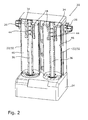
- FIGS. 1 and 2 show two different embodiments of a Adsorptionsstrockners invention 20.
- Two adsorber or cartridges 22 are inserted into a control head 24, according to Fig. 1 hanging and according to FIG. 2 standing.
- a horizontal arrangement of the cartridges 22 is possible, ultimately, the cartridges 22 can be used in any position and at any angle in the control head 24, always depending on the design of the control head 24 and the conditions on site.
- the control head 24 includes i.a. Pipe connections 26, valves 28 and not shown means for connecting the control head 24 with the cartridges 22.
- Pipe connections 26, valves 28 and not shown means for connecting the control head 24 with the cartridges 22 In the illustrated embodiment, four pilot-operated diaphragm valves and outlet side ball check valves are provided.
- the cartridges 22 on a cover 30, a cartridge shell 32 and a bottom 34.
- a central tube 36 is disposed within the cartridge and extends through the lid 30 and depending on the embodiment also through the bottom 34 therethrough.
- the cover side thus results in a free end of the central tube 36, which serves as a connection region for the control head 24.
- the individual elements of the cartridges 22 are sealed against each other by sealing means, which are arranged in the sealing means grooves 38 provided for this purpose.
- the cartridges 22 are thus designed pressure-tight.
- the cartridges 22 are provided with threads and sealing rings in the grooves 40, which need only be screwed into corresponding means for connecting the cartridges 22 to the control head 24 in the control head 24.
- the embodiment according to FIG. 3 is suitable in particular for a standing use in a control head 24.
- the fluid is introduced through the lid openings 42, which face the control head in this embodiment, in an inner space 46 of the cartridge 22, which is filled with adsorbent, not shown.
- the central tube 36 does not extend through the base 34 in this embodiment variant.
- the introduced fluid rises through the desiccant and passes to an exit dust filter 48 which retains dissolved or abraded adsorbent prior to entry into the central tube ports 44 and ultimately into the central tube 36.
- the embodiment according to FIG. 4 is particularly suitable for a suspended arrangement in a control head, the connection region of the central tube 36 is inserted from below into the control head 24.
- the fluid gets at this Embodiment through the central tube 36 into the cartridge 22 and exits through central tube openings 44 in the bottom region of this in the adsorbent.
- the central tube 36 extends through the bottom 34 and is closed by a closure cap 50.
- Fig. 5 shows the adsorption dryer according to the invention according to Fig. 1 in side view.
- One of the main advantages of this view is particularly clear, namely that the free ends of the cartridges 22 are free of connections and valve technology.
- the invention is not limited to the illustrated embodiments, but rather, for example, a hanging arrangement of the embodiment according to FIG. 3 or a standing use of the embodiment according to FIG. 4 possible.
Landscapes
- Chemical & Material Sciences (AREA)
- Engineering & Computer Science (AREA)
- Analytical Chemistry (AREA)
- General Chemical & Material Sciences (AREA)
- Oil, Petroleum & Natural Gas (AREA)
- Chemical Kinetics & Catalysis (AREA)
- Drying Of Gases (AREA)
- Drying Of Solid Materials (AREA)
Description
- Die Erfindung betrifft einen Adsorptionstrockner zur Aufbereitung von Gasen, insbesondere von Druckluft, aufweisend
- 1. einen Steuerkopf mit Ventilen, Rohranschlüssen und Mitteln zur Aufnahme von Kartuschen,
- 2. mindestens zwei mit dem Steuerkopf verbindbare und mit Trockenmittel gefüllte Kartuschen, denen über den Steuerkopf bedarfsweise ein Fluidstrom zuführbar ist und deren freie Enden frei von jeglicher Anschluss- und Ventiltechnik sind.
- Adsorptionstrockner sind in der Regel kaltregenerierend ausgeführt und seit langem im Einsatz. Von zwei mit Trockenmittel gefüllten Adsorberbehälter bzw. Kartuschen trocknet ein Adsorberbehälter den Gasstrom, der über den Steuerkopf zugeführt wird, durch Adsorption, während der andere Adsorberbehälter die Regeneration des Trockenmittels mit einem Regenerationsgasstrom bewirkt. Als Regenerationsgasstrom wird in der Regel ein annähernd auf Umgebungsdruck entspannter Teilstrom des getrockneten Gasstroms verwendet. Die Dauer der Regenerationsphase entspricht in etwa der Dauer der Adsorptionsphase, wobei sich die Regenerationsphase aufteilt in eine aktive Regenerationsphase mit Strömung der Regenerationsluft und eine passive Regenerationsphase ohne Strömung der Regenerationsluft.
- Vor Erreichen der Aufnahmekapazität des Trockenmittels erfolgt mit Hilfe von Umschaltventilen ein Umschalten der Fluidströme und damit ein Funktionstausch der beiden Adsorberbehälter. Das heißt, dass beide Behälter zwischen Adsorption und Regeneration und dazu auch zwischen Betriebsdruck und Umgebungsdruck wechseln.
- Das üblicherweise eingesetzte Trockenmittel hat nur eine begrenzte Lebensdauer, wodurch ein Austausch unumgänglich ist. Die Lebensdauer des Trockenmittels ist dabei in erster Linie von den Betriebsbedingungen vor Ort abhängig. Der Austausch des Trockenmittels sowie je nach Ausführung des Adsorptionstrockners auch der Austausch von weiteren Betätigungsmittel oder des gesamten Steuerkopfes sind aufwendig und erfordern besondere Fachkenntnisse. Zum Beispiel ist beim Befüllen des Trockenmittels wesentlich, dass die Adsorberbehälter gleichmäßig und kompakt mit Trockenmittel befüllt werden, um bei Durchströmen mit zu trocknendem Gas jede Bewegung einzelner Kugeln des Trockenmittels zu vermeiden. Hierdurch werden unzulässiger Abrieb und die Bildung offener Strömungskanäle vermieden.
- Ein gattungsgemäßer Adsorptionstrockner ist in der
DE 103 55 928 A1 beschrieben. Bei diesem können zwei Adsorberbehälter in einen Steuerkopf eingesetzt werden, so dass nach Lösen der Adsorberbehälter der Steuerkopf über die Rohranschlüsse im Fluidsystem vor Ort verbleiben kann. Sämtliche Ventile sind dabei im Steuerkopf angeordnet und können ggf. separat ausgetauscht werden. Die Adsorberbehälter sind jeweils durch ein Gehäuse gebildet, das einen Boden, einen Behältermantel und einen Deckel aufweist. In den Adsorberbehälter ist Trockenmittel enthalten, alternativ kann auch eine Trockenmittelpatrone eingesetzt werden. Die Adsorberbehälter und der Steuerkopf werden über ein Innengewinde an den Adsorberbehältern und ein am Steuerkopf angeordnetes Außengewinde miteinander verschraubt. Um eine definierte Fluidzuführung zu gewährleisten, ist als weiteres Bauteil jeweils ein Behälterkopf vorgesehen, der jeweils zwischen einem Adsorberbehälter und dem Steuerkopf eingesetzt wird. Es ist als vorteilhaft beschrieben, dass vor dem Anschrauben des Adsorberbehälters der Behälterkopf am Festteil vorzumontieren ist, so dass er dort lagerichtig gehalten wird. Die Druckfestigkeit wird durch Aufschrauben des Adsorberbehälters hergestellt. - Grundsätzlich verbessert die vorgeschlagene Vorrichtung die Wartung und Instandhaltung des Adsorptionstrockners vor Ort bereits, dennoch ist der Aufbau kompliziert und auch der Austausch der Adsorberbehälter vor Ort nicht schnell und einfach möglich. Weiterhin sind Längenvariationen und Durchmesservarianten der Adsorberbehälter in Anpassung an die Gegebenheiten vor Ort nur mit erheblichem Aufwand möglich. Aufgrund der Gewindeverbindung sind der Außendurchmesser der Adsorberbehälter und der Anschlußbereich des Steuerkopfs vorgegeben.
- Die Aufgabe der vorliegenden Erfindung besteht darin, einen Adsorptionstrockner zu schaffen, der eine schnelle und einfache Wartung und Instandhaltung vor Ort ermöglicht. Insbesondere soll es möglich sein, die Adsorberbehälter schnell und einfach auszutauschen. Eine Anpassung der Dimensionen der Adsorberbehälter an die Gegebenheiten vor Ort soll ohne aufwendige konstruktive Maßnahmen realisierbar sein. Schließlich soll die Druckdichtigkeit der Adsorberbehälter im Betrieb höchsten Anforderungen entsprechen. Die Nachteile des Standes der Technik sollen vermieden werden.
- Die Aufgabe wird erfindungsgemäß durch einen gattungsgemäßen Adsorptionstrockner gelöst, bei dem
- 3. jeweils der Deckel, der Kartuschenmantel und der Boden der Kartuschen über das Zentralrohr miteinander verspannbar sind,
- 4. das Zentralrohr jeweils aus der Kartusche herausragt und als Anschlussmittel für den Steuerkopf dient,
- 5. ein außerhalb des Deckels (30) angeordneter Bereich des Zentralrohrs (36) als Anschlussbereich für die Verbindung mit dem Steuerkopf (24) dient,
- 6. die Kartusche selbst druckdicht ausgeführt ist.
- 7. der Verbindungsbereich des Zentralrohrs (36) und die Mittel zur Aufnahme der Kartuschen (22) als Schnellverbindung ausgeführt sind.
- Die Erfindung schlägt somit vor, als Adsorberbehälter Kartuschen einzusetzen, die bereits druckdicht ausgeführt sind, so dass die Druckdichtigkeit des Systems bzw. des Adsorptionstrockners nicht erst bei der Installation vor Ort erfolgt. Bei einem Austausch der Kartuschen können diese vom Adsorptionstrockner abgenommen und durch neue oder bereits neu befüllte Kartuschen ersetzt werden. Die Kartuschen mit verbrauchtem Trockenmittel werden beim Hersteller oder einen Serviceunternehmen neu befüllt, wobei die Druckdichtigkeit der Kartuschen bereits im Vorfeld im Werk getestet werden kann. Damit ist die Gefahr minimiert, dass bei einem Austausch der Kartuschen eine Leckage verursacht wird.
- Die Verbindung der Kartuschen mit dem Steuerkopf erfolgt unmittelbar über das Zentralrohr selbst. In einer besonders vorteilhaften Ausführungsvariante steht ein freies Ende des Zentralrohrs gegenüber der Kartusche bzw. gegenüber dem Deckel vor und kann in eine entsprechende Öffnung des Steuerkopfs in diesen eingesetzt werden. Hierzu kann das Zentralrohr beispielsweise auf seiner Außenseite des freien Endes ein Gewinde aufweisen, das in ein Innengewinde der Öffnung des Steuerkopfs einschraubbar ist, vorteilhafterweise ist aber eine Schnellverbindung vorgesehen. Derartige Schnellverbindungen oder vereinfachte Anschlussvorrichtungen sind aus der Drucklufttechnik bereits bekannt. Beispielsweise kann das Zentralrohr hierzu an seinem freien Ende, also dem Anschlussbereich, eine oder mehrere umlaufende Nuten aufweisen, in die ein entsprechendes Element eines im Steuerkopf angeordneten Verbindungsmittels eingreift. Die Kartuschen müssen in diesem Fall lediglich in eine der Öffnungen des Steuerkopfs hineingedrückt oder eingesteckt werden, der Anschlussbereich des Zentralrohrs rastet dann innerhalb des Steuerkopfes ein und eine druckdichte Verbindung ist gewährleistet. Alternativ ist auch eine Schraubverbindung denkbar, wobei geeignete Dichtelemente eine ausreichende Dichtigkeit bewirken. Die Dichtelement können beispielsweise als Dichtringe ausgeführt sein, die in Nuten gehalten sind.
- Ein wesentlicher Vorteil der Erfindung besteht auch darin, dass die Befüllung der Kartuschen werkseitig vorgenommen werden kann und somit höchsten Anforderungen entsprechen kann. Es kann eine dichtere Schüttung erreicht werden, die im Betrieb nahezu abriebsfrei arbeitet. Fehler bei der Befüllung und ungewollte Lekagen des Behälters sind somit nahezu ausgeschlossen.
- Der Steuerkopf beinhaltet die gesamte Ventiltechnik und die notwendigen Rohranschlüsse und Behälterverbindungen. Dadurch ist das zweite Ende der Kartusche frei von jeglicher Anschluss- und Ventiltechnik, was den Kartuschenwechsel sehr einfach macht. Somit ist auch eine einfache Wartung und Instandhaltung des Steuerkopfs möglich, denkbar ist beispielsweise ein Austausch des gesamten Steuerkopfs bei anschließender Weiterverwendung der noch nicht vollständig aufgebrauchten Kartuschen. Der Steuerkopf kann erfindungsgemäß beispielsweise vier vorgesteuerte Membranventile für die Druckluftzufuhr bzw. Spülluftabfuhr aufweisen, wobei zwei Kugelrückschlagventile austrittsseitig vorgesehen sind. Auch können unterschiedliche Steuerkopfgrößen bei gleicher Kartuschengröße problemlos realisiert werden, da lediglich die Verbindung des Anschlussbereiches des Zentralrohrs mit dem Steuerkopf Voraussetzung für einen funktionsfähigen Adsorptionstrockner sind.
- Dadurch, dass das Zentralrohr selbst als Zugstange genutzt wird, die den Deckel und den Boden der Kartusche gegen den Kartuschenmantel verspannen, ist eine Anpassung der Größe und Dimension einer Kartusche beispielsweise an Gegebenheiten vor Ort oder bei Veränderung einer Produktionsserie ebenfalls schnell, einfach und problemlos möglich. Der Durchmesser und die Länge einer Kartusche ist für eine mögliche Verbindung mit einem bereits vor Ort eingesetzten Steuerkopf unerheblich, lediglich der Durchmesser und die Ausführung des Anschlußbereichs des Zentralrohrs ist von Bedeutung. Somit kann beispielsweise die Länge einer Kartusche durch Austausch des Kartuschenmantels schnell und einfach verändert werden und die Druckdichtigkeit durch Verspannen der Komponenten gegeneinander gewährleistet werden.
- Bei den erfindungsgemäßen Kartuschen gibt es zwei verschiedene Möglichkeiten zur Einleitung des Fluids. In einer ersten Variante wird das Fluid durch eine oder mehrere Deckelöffnungen im Deckel durch diesen hindurch in das Trockenmittel eingeleitet, strömt im Bodenbereich der Kartusche durch Zentralrohröffnungen in das Zentralrohr und wird durch das Zentralrohr zurück in den Steuerkopf geleitet. Zur Regenerierung der Kartusche wird die Strömungsrichtung umgekehrt, Spülluft wird über das Zentralrohr und durch die Öffnungen im Bodenbereich in das Trockenmittel eingeleitet und somit das Trockenmittel regeneriert.
- In der zweiten Ausführungsvariante ist die Strömungsrichtung umgekehrt. Das Fluid strömt durch das Zentralrohr zum Bodenbereich, tritt dort aus dem Zentralrohr aus, strömt von unten nach oben durch das Trockenmittel und schließlich durch Deckelöffnungen wieder aus der Kartusche heraus.
- Die zweite Variante wird bevorzugt dann eingesetzt, wenn die Kartuschen hängend im Steuerkopf angeordnet sind. Im Bodenbereich nach dem Zentralrohr können sich dann eventuell Kondensattröpfchen abscheiden, sammeln und verbleiben. Erfindungsgemäß kann hierfür eine Kammer vorgesehen werden. Alternativ kann die Kammer bzw. der Raum vorteilhafterweise mit Trockenmittel aufgefüllt werden. Bei der Regeneration (Rücktrocknung durch Spülluft) wird diese Feuchte dann automatisch mit ausgetragen, das Kondensat muss nicht manuell abgeführt werden. Eine eigene Kammer oder ein eigener Raum für das anfallende Kondensat kann vorteilhaft sein, ist aber nicht unbedingt notwendig.
- In beiden Ausführungsvarianten kann erfindungsgemäß im Bereich des Austritts des Fluids aus dem Trockenmittel, also bei der ersten Variante vor den Zentralrohröffnungen und bei der zweiten Variante vor den Deckelöffnungen, ein Filterelement vorgesehen sein. Dieses verhindert einen Austrag von Abrieb des Trockenmittels aus der Kartusche.
- Auch kann erfindungsgemäß ein Schalldämpfer vorgesehen sein, der beispielsweise zwischen den Kartuschen angeordnet ist und die Geräuschentwicklung des Adsorptionstrockners deutlich reduziert.
- Erfindungsgemäß hat sich eine hängende Anordnung der Kartuschen in dem Steuerkopf als besonders vorteilhaft erwiesen. Dies bedeutet, dass die Kartuschen von unten in Öffnungen bzw. Verbindungsmittel des Steuerkopfs eingesetzt werden und frei in diesem hängen. Alternativ ist aber auch eine umgekehrte Anordnung möglich, nämlich dass die Kartuschen von oben in den Steuerkopf eingesetzt werden und sozusagen auf diesem stehen. Schließlich ist ebenfalls eine seitliche Anordnung, bei der die Kartuschen beispielsweise horizontal ausgerichtet sind, denkbar, wenn dies aufgrund der Gegebenheiten vor Ort vorteilhaft sein sollte.
- Die Öffnungen des Steuerkopfs sind in diesem Fall entsprechend angeordnet. Der Adsorptionstrockner kann eine Wandhalterung aufweisen, je nach Ausführung der Rohrleitung kann aber auf eine solche Wandhalterung auch verzichtet werden.
- Der Deckel, der Boden und der Kartuschenmantel sind vorzugsweise über geeignete Dichtmittel, beispielsweise O-Ringe gegeneinander abgedichtet. Um ein Verspannen der Elemente gegeneinander zu ermöglichen, kann das Zentralrohr auf seiner Außenseite ein Gewinde aufweisen, auf das der Boden oder der Deckel aufgeschraubt werden können. Denkbar ist aber auch, dass der Boden und der Deckel lediglich über Öffnungen auf das Zentralrohr aufgeschoben und über eine außen angeordnete Mutter verspannt werden. In diesem Fall erstreckt sich das Zentralrohr nicht nur durch den Deckel, sondern auch durch den Boden der Kartusche, wodurch das Zentralrohr dann auf der Deckelseite den Anschlussbereich für den Steuerkopf und auf der Bodenseite einen Verspannungsabschnitt mit einem Außengewinde ausbildet.
- Da die erfindungsgemäße Kartusche selbst bereits druckdicht ausgeführt ist, ist ein weiteres druckdichtes Gehäuse, das die Kartusche umgibt, nicht notwendig. Hierdurch wird aufgrund der Einsparung des Gehäuses Material und Gewicht eingespart, was auch bei der Installation des Adsorptionstrockners vor Ort vorteilhaft ist. Das geringere Eigengewicht des Adsorptionstrockners verbessert die Möglichkeiten eines hängenden Einbaus und macht auch die Servicearbeiten einfacher. Durch den Verzicht auf das Gehäuse baut der Adsorptionstrockner insgesamt kleiner, was insbesondere bei Adsorptionstrocknern mit geringer Leistung vorteilhaft ist, da diese häufig in Endstellennähe betrieben und/oder als Einbaugeräte verwendet werden.
- Der erfindungsgemäße Adsorptionstrockner kann für unterschiedlichste Anforderungen ausgelegt sein, er eignet sich insbesondere für Fluidströme von etwa 3 Nm3/h bis etwa 150 Nm3/h (Normkubikmeter Luft pro Stunde).
- Der erfindungsgemäße Adsorptionstrockner eignet sich insbesondere für eine Kombination mit einem Eingangsfilter (Feinstfilter), vorteilhafterweise kann dieser auch in den Adsorptionstrockner integriert sein. Er weist eine Schnittstelle zur Übertragung von Alarm- und Wartungsmeldungen auf und ist vorteilhafterweise elektronisch gesteuert. Auch kann ein zweiter Eingangsfilter (Mikrofilter) vorgesehen sein.
- Der Steuerkopf kann erfindungsgemäß Mittel vorsehen, die ein Verschwenken des Steuerkopfes mit den Kartuschen im eingebauten Zustand ermöglichen. Durch Verschwenken des gesamten Steuerkopfs mit den Kartuschen können diese in eine Position gebracht werden, in der ausreichend Raum zum Entnehmen und Einfügen der Kartuschen zur Verfügung steht. Denkbar ist auch, dass nicht der gesamte Steuerkopf verschwenkbar ausgeführt ist, sondern lediglich derjenige Bereich, der die Mittel zur Verbindung der Kartuschen zum Steuerkopf aufweist. Ein zweiter Bereich, der beispielsweise die Rohranschlüsse aufweist, verbleibt dagegen in seiner Position. Der Steuerkopf ist bei dieser Ausführungsvariante in einen schwenkbaren und in einen nicht schwenkbaren Teilbereich unterteilt.
- Der Steuerkopf kann außerdem erfindungsgemäß Mittel in Form von Anschlussstücken vorsehen, die durch Montage in unterschiedlichen Positionen ein Wechseln der Ein- und Austrittsanschlüsse ermöglichen. Damit ist eine umgekehrte Durchflussrichtung des Steuerkopfes in der Rohrleitung ermöglicht. Dies ist vorteilhaft für die Anpassung an die Gegebenheiten am Aufstellungsort.
- Mit Hilfe der nachfolgenden Figuren wird die Erfindung näher erläutert. Die gezeigten Ausführungsvarianten sind dabei nur beispielhaft zu verstehen und sollen die Erfindung nicht auf diese beschränken. Es zeigen:
- Fig. 1:
- einen erfindungsgemäßen Adsorptionstrockner mit hängenden Kartuschen im Schnitt,
- Fig. 2:
- einen erfindungsgemäßen Adsorptionstrockner mit stehenden Kartuschen, teilweise geschnitten,
- Fig. 3:
- eine erfindungsgemäße Kartusche im Schnitt,
- Fig. 4:
- eine zweite Ausführungsvariante einer erfindungsgemäßen Kartusche im Schnitt,
- Fig. 5:
- ein Adsorptionstrockner gemäß
Fig. 1 in Seitenansicht. - Die
Figuren 1 und2 zeigen zwei verschiedene Ausführungsvarianten eines erfindungsgemäßen Adsorptionstrockners 20. Zwei Adsorberbehälter bzw. Kartuschen 22 sind in einen Steuerkopf 24 eingesetzt, gemäßFig. 1 hängend und gemäßFigur 2 stehend. Auch eine horizontale Anordnung der Kartuschen 22 ist möglich, letztendlich können die Kartuschen 22 in jeder beliebigen Position und unter beliebigen Winkeln in den Steuerkopf 24 eingesetzt werden, stets abhängig von der Ausführung des Steuerkopfes 24 und den Bedingungen vor Ort. - Der Steuerkopf 24 beinhaltet u.a. Rohranschlüsse 26, Ventile 28 und nicht gezeigte Mittel zur Verbindung des Steuerkopfs 24 mit den Kartuschen 22. Im gezeigten Ausführungsbeispiel sind vier vorgesteuerte Membranventile sowie austrittsseitig Kugelrückschlagventile vorgesehen.
- Wie sich aus den
Figuren 1 bis 4 ergibt, weisen die Kartuschen 22 einen Deckel 30, einen Kartuschenmantel 32 und einen Boden 34 auf. Ein Zentralrohr 36 ist innerhalb der Kartusche angeordnet und erstreckt sich durch den Deckel 30 und je nach Ausführungsvariante auch durch den Boden 34 hindurch. Deckelseitig ergibt sich somit ein freies Ende des Zentralrohrs 36, das als Anschlussbereich für den Steuerkopf 24 dient. Die einzelnen Elemente der Kartuschen 22 sind durch Dichtmittel gegeneinander abgedichtet, die in die dafür vorgesehenen Dichtmittelnuten 38 angeordnet sind. Die Kartuschen 22 sind somit druckdicht ausgeführt. - Im gezeigten Ausführungsbeispiel gemäß der
Figuren 3 und4 sind die Kartuschen 22 mit Gewinden und Dichtungsringen in den Nuten 40 versehen, die in entsprechende Mittel zur Verbindung der Kartuschen 22 mit dem Steuerkopf 24 lediglich in den Steuerkopf 24 eingeschraubt werden müssen. - Alternativ ist z.B. auch eine Bajonett- oder Steckverbindung denkbar. Ein Verschrauben und somit ein mehrfaches Drehen der Kartuschen 22 um die eigene Achse ist dann nicht notwendig. Hierfür weist das jeweilige Zentralrohr 36 im Anschlußbereich Anschlussnuten 40 auf, die mit entsprechenden Mitteln des Steuerkopfs 24 zusammenwirken. Im Deckel 30 sind Deckelöffnungen 42 und im Zentralrohr 36 im Bodenbereich Zentralrohröffnungen 44 erkennbar.
- Die Ausführungsvariante gemäß
Figur 3 eignet sich im Besonderen für einen stehenden Einsatz in einem Steuerkopf 24. Dies bedeutet, dass der Anschlußbereich des Zentralrohrs 36 von oben in eine entsprechende Öffnung des Steuerkopfs 24 eingesetzt wird. Das Fluid wird durch die Deckelöffnungen 42, die in dieser Ausführungsvariante dem Steuerkopf zugewandt sind, in einen Innenraum 46 der Kartusche 22 eingeleitet, der mit nicht gezeigten Adsorptionsmittel gefüllt ist. Erkennbar ist auch, dass sich das Zentralrohr 36 in dieser Ausführungsvariante nicht durch den Boden 34 hindurch erstreckt. - Das eingeleitete Fluid steigt durch das Trockenmittel auf und gelangt zu einem Austrittsstaubfilter 48, der gelöstes oder abgeriebenes Adsorptionsmittel vor dem Eintritt in die Zentralrohröffnungen 44 und schließlich in das Zentralrohr 36 zurückhält.
- Die Ausführungsvariante gemäß
Figur 4 eignet sich insbesondere für eine hängende Anordnung in einem Steuerkopf, der Anschlußbereich des Zentralrohrs 36 wird von unten in den Steuerkopf 24 eingeführt. Das Fluid gelangt bei dieser Ausführungsvariante durch das Zentralrohr 36 in die Kartusche 22 und tritt durch Zentralrohröffnungen 44 im Bodenbereich aus diesem in das Adsorptionsmittel aus. Im Innenraum 26 steigt es dann bis zum Austrittsstaubfilter 48 auf, durchströmt diesen und entweicht durch die Deckelöffnung 42. Bei dieser Ausführungsvariante erstreckt sich das Zentralrohr 36 durch den Boden 34 hindurch und ist durch eine Verschlusskappe 50 verschlossen. -
Fig. 5 zeigt den erfindungsgemäßen Adsorptionstrockner gemäßFig. 1 in Seitenansicht. Einer der wesentlichen Vorteile wird durch diese Ansicht besonders deutlich, nämlich dass die freien Enden der Kartuschen 22 frei von Anschlüssen und Ventiltechnik sind. - Die Erfindung ist nicht auf die dargestellte Ausführungsvarianten beschränkt, vielmehr ist beispielsweise auch eine hängende Anordnung der Ausführungsvariante gemäß
Figur 3 bzw. ein stehender Einsatz der Ausführungsvariante gemäßFigur 4 möglich. Das gleiche gilt für die unterschiedliche Ausführung der Bodenbereiche. Sowohl für die stehende, also auch für die hängende Variante können beide Arten die Befestigung des Bodens 34 verwendet werden.
Claims (8)
- Adsorptionstrockner (20) zum Aufbereiten von Gasen, insbesondere von Druckluft, aufweisend1. einen Steuerkopf (24) mit Ventilen (28), Rohranschlüssen (26) und Mittel zur Aufnahme von Kartuschen,2. mindestens zwei mit dem Steuerkopf (24) verbindbare und mit Adsorptionsmittel gefüllte Kartuschen (22), denen über den Steuerkopf (24) bedarfsweise ein Fluidstrom zuführbar ist und deren freie Enden frei von jeglicher Anschluss- und Ventiltechnik sind.
wobei die Kartuschen (22) jeweils einen Deckel (30), einen Kartuschenmantel (32), einen Boden (34) sowie ein Zentralrohr (36), das sich durch den Deckel (30) in einen Innenraum (46) der Kartusche (22) erstreckt, aufweisen
, wobei3. jeweils der Deckel (30), der Kartuschenmantel (32) und der Boden (34) der Kartuschen (22) über das Zentralrohr (36) miteinander verspannbar sind,4. das Zentralrohr (36) jeweils aus der Kartusche (22) herausragt und als Anschlussmittel für den Steuerkopf (24) dient,5. ein außerhalb des Deckels (30) angeordneter Bereich des Zentralrohrs (36) als Anschlussbereich für die Verbindung mit dem Steuerkopf (24) dient,6. die Kartusche (22) selbst druckdicht ausgeführt ist.
dadurch gekennzeichnet, dass7. der Verbindungsbereich des Zentralrohrs (36) und die Mittel zur Aufnahme der Kartuschen (22) als Schnellverbindung ausgeführt sind. - Adsorptionstrockner (20) nach Anspruch 1, dadurch gekennzeichnet, dass die Schnellverbindung als Einsteckverbindung ausgeführt ist.
- Adsorptionstrockner (20) nach Anspruch 1, dadurch gekennzeichnet, dass die Schnellverbindung als Bajonettverbindung ausgeführt ist.
- Adsorptionstrockner (20) nach einem der Ansprüche 1 bis 3, dadurch gekennzeichnet, dass die Kartuschen (22) hängend im Steuerkopf (24) angeordnet sind.
- Adsorptionstrockner (20) nach einem der Ansprüche 1 bis 3, dadurch gekennzeichnet, dass die Kartuschen (22) stehend im Steuerkopf (24) angeordnet sind.
- Adsorptionstrockner (20) nach einem der Ansprüche 1 bis 5, dadurch gekennzeichnet, dass im Innenraum (46), der Kartuschen (22) ein Austrittsstaubfilter (48) angeordnet ist.
- Adsorptionstrockner (20) nach einem der Ansprüche 1 bis 6, dadurch gekennzeichnet, dass durch Wechsel eines Anschlussstückes Ein- und Austrittsanschluss wechselbar sind.
- Adsorptionstrockner (20) nach einem der Ansprüche 1 bis 6, dadurch gekennzeichnet, dass die Kartuschen (22) im eingesetzten Zustand schwenkbar ausgeführt sind.
Applications Claiming Priority (2)
| Application Number | Priority Date | Filing Date | Title |
|---|---|---|---|
| DE102010036382A DE102010036382B9 (de) | 2010-07-13 | 2010-07-13 | Adsorbtionstrockner |
| PCT/EP2011/061776 WO2012007433A2 (de) | 2010-07-13 | 2011-07-11 | Kompakter adsorbtionstrockner |
Publications (2)
| Publication Number | Publication Date |
|---|---|
| EP2593209A2 EP2593209A2 (de) | 2013-05-22 |
| EP2593209B1 true EP2593209B1 (de) | 2016-01-13 |
Family
ID=44628512
Family Applications (1)
| Application Number | Title | Priority Date | Filing Date |
|---|---|---|---|
| EP11732432.7A Not-in-force EP2593209B1 (de) | 2010-07-13 | 2011-07-11 | Kompakter adsorptionstrockner |
Country Status (7)
| Country | Link |
|---|---|
| US (1) | US8906144B2 (de) |
| EP (1) | EP2593209B1 (de) |
| JP (1) | JP5690929B2 (de) |
| KR (1) | KR101510573B1 (de) |
| CN (1) | CN103068467B (de) |
| DE (1) | DE102010036382B9 (de) |
| WO (1) | WO2012007433A2 (de) |
Families Citing this family (3)
| Publication number | Priority date | Publication date | Assignee | Title |
|---|---|---|---|---|
| US9061238B2 (en) * | 2013-03-15 | 2015-06-23 | Invacare Corporation | Gas concentrator |
| RU2668653C2 (ru) * | 2014-06-26 | 2018-10-02 | Дональдсон Фильтрейшн Дойчланд Гмбх | Устройство для размещения в емкости сорбционного осушителя для текучей среды, емкость сорбционного осушителя и система |
| BE1028303B1 (nl) * | 2020-05-13 | 2021-12-16 | Atlas Copco Airpower Nv | Inrichting en werkwijze voor het adsorberen van een gas uit een te behandelen gasmengsel |
Family Cites Families (13)
| Publication number | Priority date | Publication date | Assignee | Title |
|---|---|---|---|---|
| JPH062733Y2 (ja) * | 1985-12-05 | 1994-01-26 | 株式会社ナブコ | 2筒式除湿装置 |
| US4673420A (en) | 1986-02-10 | 1987-06-16 | Haker Leroy C | Desiccant dryer |
| JPH062735Y2 (ja) * | 1986-10-07 | 1994-01-26 | 食品環境開発株式会社 | 歯科医療用除湿乾燥空気生成装置 |
| US5403387A (en) | 1991-09-06 | 1995-04-04 | Reading Technologies, Inc. | Apparatus for removing moisture from a gas |
| DE4409871C2 (de) * | 1994-03-22 | 2001-08-30 | Knorr Bremse Systeme | Trocknungspatrone für Lufttrocknungsanlagen von Druckluftbremsanlagen von Fahrzeugen |
| JPH08229344A (ja) * | 1995-02-27 | 1996-09-10 | Tohoku Electric Power Co Inc | 吸湿装置 |
| JP3983839B2 (ja) * | 1996-12-12 | 2007-09-26 | 東北電力株式会社 | 吸湿呼吸器 |
| JP4723130B2 (ja) * | 2001-08-08 | 2011-07-13 | シーケーディ株式会社 | 吸着分離装置 |
| US6692556B2 (en) * | 2001-10-29 | 2004-02-17 | Stanhope Products Co. | Desiccant cartridge with elongated center tube |
| DE10355928A1 (de) * | 2003-11-29 | 2005-06-30 | Tepcon Engineering Gesellschaft Mbh | Adsorptionstrockner mit vereinfachter Austauschbarkeit der Verschleißteile und Verfahren zum Austauschen |
| DE102004030737A1 (de) * | 2004-06-25 | 2006-01-12 | Degussa Ag | Verfahren und Vorrichtung zur Extraktion von Stoffen aus silanmodifizierten Füllstoffen |
| WO2006121932A1 (en) * | 2005-05-08 | 2006-11-16 | 3M Innovative Properties Company | Filter cartridge and method of construction thereof |
| DE102006037311A1 (de) * | 2006-08-08 | 2008-02-14 | Knorr-Bremse Systeme für Nutzfahrzeuge GmbH | Druckluftversorgungseinrichtung |
-
2010
- 2010-07-13 DE DE102010036382A patent/DE102010036382B9/de not_active Expired - Fee Related
-
2011
- 2011-07-11 US US13/809,670 patent/US8906144B2/en not_active Expired - Fee Related
- 2011-07-11 JP JP2013519060A patent/JP5690929B2/ja not_active Expired - Fee Related
- 2011-07-11 WO PCT/EP2011/061776 patent/WO2012007433A2/de not_active Ceased
- 2011-07-11 KR KR1020137003594A patent/KR101510573B1/ko not_active Expired - Fee Related
- 2011-07-11 CN CN201180031026.7A patent/CN103068467B/zh not_active Expired - Fee Related
- 2011-07-11 EP EP11732432.7A patent/EP2593209B1/de not_active Not-in-force
Also Published As
| Publication number | Publication date |
|---|---|
| CN103068467A (zh) | 2013-04-24 |
| JP2013533803A (ja) | 2013-08-29 |
| CN103068467B (zh) | 2014-12-10 |
| DE102010036382B3 (de) | 2011-10-13 |
| JP5690929B2 (ja) | 2015-03-25 |
| WO2012007433A2 (de) | 2012-01-19 |
| WO2012007433A3 (de) | 2012-03-22 |
| DE102010036382B9 (de) | 2012-03-22 |
| KR101510573B1 (ko) | 2015-04-08 |
| US20130199374A1 (en) | 2013-08-08 |
| KR20130065690A (ko) | 2013-06-19 |
| US8906144B2 (en) | 2014-12-09 |
| EP2593209A2 (de) | 2013-05-22 |
Similar Documents
| Publication | Publication Date | Title |
|---|---|---|
| EP0867670B1 (de) | Kondensator für eine Klimaanlage eines Kraftfahrzeuges und Einsatz in einem solchen Kondensator | |
| DE102009030897B4 (de) | Lufttrocknerpatrone für eine Druckluftaufbereitungsanlage eines Fahrzeugs und Druckluftaufbereitungsanlage für ein Fahrzeug mit einer entsprechenden Lufttrocknerpatrone. | |
| EP2768598A1 (de) | Luftfilterpatrone zur druckluftaufbereitung für eine druckluftaufbereitungsanlage | |
| DE102006037311A1 (de) | Druckluftversorgungseinrichtung | |
| EP3849684A1 (de) | Filterelement mit einem trockenmittel enthaltenden aufnahmeraum und fluidfilter | |
| DE102010036382B3 (de) | Adsorbtionstrockner | |
| DE3514989A1 (de) | Druckluftversorgungseinrichtung fuer fahrzeug-druckluftanlagen | |
| DE202022103046U1 (de) | Filterelement zum Abscheiden von Öldampf aus einem Gasstrom | |
| DE69412782T2 (de) | Druckwechseladsorptionsvorrichtung - Ventilbetätigung | |
| DE112016006951B4 (de) | Behälter | |
| DE102009005156A1 (de) | Vorrichtung zum sorptiven Trennen eines Gasstroms | |
| DE102014009292A1 (de) | Vorrichtung zum Anordnen in einem Behälter eines Sorptionstrockners für ein Fluid, Behälter eines Sorptionstrockners und System | |
| EP1561077A1 (de) | Sammelbehälter, wärmetauscher und kältemittelkreislauf | |
| EP1991338A1 (de) | Trockenvorrichtung für druckluft und andere gasförmige medien und verfahren zum betreiben einer solchen | |
| EP2801672B1 (de) | Systemtrenner | |
| DE102007034581B4 (de) | Luftleitungsanschluss | |
| DE3815937A1 (de) | Druckbehaelter | |
| DE3232902A1 (de) | Vorrichtung zur be- und entlueftung von geschlossenen behaeltern oder gehaeusen | |
| DE102008039213B4 (de) | Filtereinrichtung für Vakuumpumpen | |
| DE102006003551B4 (de) | Filtereinrichtung zur Flüssigkeitsfilterung | |
| EP3160620B1 (de) | Vorrichtung zum anordnen in einem behälter eines sorptionstrockners für ein fluid, behälter eines sorptionstrockners und system | |
| DE10355928A1 (de) | Adsorptionstrockner mit vereinfachter Austauschbarkeit der Verschleißteile und Verfahren zum Austauschen | |
| EP3237094B1 (de) | Vorrichtung zum dämpfen eines schalls eines abgases, system umfassend eine derartige vorrichtung, sorptionstrockner mit einer derartigen vorrichtung sowie verfahren zum dämpfen eines schalls eines abgases | |
| DE202017102605U1 (de) | Ventilkombination | |
| DE102023112279A1 (de) | Zweistufig adsorptiv wirksames Sicherheitskonzept |
Legal Events
| Date | Code | Title | Description |
|---|---|---|---|
| PUAI | Public reference made under article 153(3) epc to a published international application that has entered the european phase |
Free format text: ORIGINAL CODE: 0009012 |
|
| 17P | Request for examination filed |
Effective date: 20130114 |
|
| AK | Designated contracting states |
Kind code of ref document: A2 Designated state(s): AL AT BE BG CH CY CZ DE DK EE ES FI FR GB GR HR HU IE IS IT LI LT LU LV MC MK MT NL NO PL PT RO RS SE SI SK SM TR |
|
| DAX | Request for extension of the european patent (deleted) | ||
| GRAP | Despatch of communication of intention to grant a patent |
Free format text: ORIGINAL CODE: EPIDOSNIGR1 |
|
| INTG | Intention to grant announced |
Effective date: 20150717 |
|
| GRAS | Grant fee paid |
Free format text: ORIGINAL CODE: EPIDOSNIGR3 |
|
| GRAA | (expected) grant |
Free format text: ORIGINAL CODE: 0009210 |
|
| AK | Designated contracting states |
Kind code of ref document: B1 Designated state(s): AL AT BE BG CH CY CZ DE DK EE ES FI FR GB GR HR HU IE IS IT LI LT LU LV MC MK MT NL NO PL PT RO RS SE SI SK SM TR |
|
| REG | Reference to a national code |
Ref country code: GB Ref legal event code: FG4D Free format text: NOT ENGLISH |
|
| REG | Reference to a national code |
Ref country code: CH Ref legal event code: EP |
|
| REG | Reference to a national code |
Ref country code: IE Ref legal event code: FG4D Free format text: LANGUAGE OF EP DOCUMENT: GERMAN |
|
| REG | Reference to a national code |
Ref country code: AT Ref legal event code: REF Ref document number: 770130 Country of ref document: AT Kind code of ref document: T Effective date: 20160215 |
|
| REG | Reference to a national code |
Ref country code: DE Ref legal event code: R096 Ref document number: 502011008672 Country of ref document: DE |
|
| REG | Reference to a national code |
Ref country code: LT Ref legal event code: MG4D |
|
| REG | Reference to a national code |
Ref country code: NL Ref legal event code: MP Effective date: 20160113 |
|
| PG25 | Lapsed in a contracting state [announced via postgrant information from national office to epo] |
Ref country code: NL Free format text: LAPSE BECAUSE OF FAILURE TO SUBMIT A TRANSLATION OF THE DESCRIPTION OR TO PAY THE FEE WITHIN THE PRESCRIBED TIME-LIMIT Effective date: 20160113 |
|
| PG25 | Lapsed in a contracting state [announced via postgrant information from national office to epo] |
Ref country code: NO Free format text: LAPSE BECAUSE OF FAILURE TO SUBMIT A TRANSLATION OF THE DESCRIPTION OR TO PAY THE FEE WITHIN THE PRESCRIBED TIME-LIMIT Effective date: 20160413 Ref country code: HR Free format text: LAPSE BECAUSE OF FAILURE TO SUBMIT A TRANSLATION OF THE DESCRIPTION OR TO PAY THE FEE WITHIN THE PRESCRIBED TIME-LIMIT Effective date: 20160113 Ref country code: FI Free format text: LAPSE BECAUSE OF FAILURE TO SUBMIT A TRANSLATION OF THE DESCRIPTION OR TO PAY THE FEE WITHIN THE PRESCRIBED TIME-LIMIT Effective date: 20160113 Ref country code: ES Free format text: LAPSE BECAUSE OF FAILURE TO SUBMIT A TRANSLATION OF THE DESCRIPTION OR TO PAY THE FEE WITHIN THE PRESCRIBED TIME-LIMIT Effective date: 20160113 Ref country code: GR Free format text: LAPSE BECAUSE OF FAILURE TO SUBMIT A TRANSLATION OF THE DESCRIPTION OR TO PAY THE FEE WITHIN THE PRESCRIBED TIME-LIMIT Effective date: 20160414 |
|
| PG25 | Lapsed in a contracting state [announced via postgrant information from national office to epo] |
Ref country code: IS Free format text: LAPSE BECAUSE OF FAILURE TO SUBMIT A TRANSLATION OF THE DESCRIPTION OR TO PAY THE FEE WITHIN THE PRESCRIBED TIME-LIMIT Effective date: 20160513 Ref country code: PT Free format text: LAPSE BECAUSE OF FAILURE TO SUBMIT A TRANSLATION OF THE DESCRIPTION OR TO PAY THE FEE WITHIN THE PRESCRIBED TIME-LIMIT Effective date: 20160513 Ref country code: RS Free format text: LAPSE BECAUSE OF FAILURE TO SUBMIT A TRANSLATION OF THE DESCRIPTION OR TO PAY THE FEE WITHIN THE PRESCRIBED TIME-LIMIT Effective date: 20160113 Ref country code: LV Free format text: LAPSE BECAUSE OF FAILURE TO SUBMIT A TRANSLATION OF THE DESCRIPTION OR TO PAY THE FEE WITHIN THE PRESCRIBED TIME-LIMIT Effective date: 20160113 Ref country code: SE Free format text: LAPSE BECAUSE OF FAILURE TO SUBMIT A TRANSLATION OF THE DESCRIPTION OR TO PAY THE FEE WITHIN THE PRESCRIBED TIME-LIMIT Effective date: 20160113 Ref country code: PL Free format text: LAPSE BECAUSE OF FAILURE TO SUBMIT A TRANSLATION OF THE DESCRIPTION OR TO PAY THE FEE WITHIN THE PRESCRIBED TIME-LIMIT Effective date: 20160113 Ref country code: LT Free format text: LAPSE BECAUSE OF FAILURE TO SUBMIT A TRANSLATION OF THE DESCRIPTION OR TO PAY THE FEE WITHIN THE PRESCRIBED TIME-LIMIT Effective date: 20160113 |
|
| REG | Reference to a national code |
Ref country code: DE Ref legal event code: R097 Ref document number: 502011008672 Country of ref document: DE |
|
| PG25 | Lapsed in a contracting state [announced via postgrant information from national office to epo] |
Ref country code: EE Free format text: LAPSE BECAUSE OF FAILURE TO SUBMIT A TRANSLATION OF THE DESCRIPTION OR TO PAY THE FEE WITHIN THE PRESCRIBED TIME-LIMIT Effective date: 20160113 Ref country code: DK Free format text: LAPSE BECAUSE OF FAILURE TO SUBMIT A TRANSLATION OF THE DESCRIPTION OR TO PAY THE FEE WITHIN THE PRESCRIBED TIME-LIMIT Effective date: 20160113 |
|
| PGFP | Annual fee paid to national office [announced via postgrant information from national office to epo] |
Ref country code: IT Payment date: 20160721 Year of fee payment: 6 Ref country code: DE Payment date: 20160721 Year of fee payment: 6 Ref country code: GB Payment date: 20160722 Year of fee payment: 6 |
|
| PLBE | No opposition filed within time limit |
Free format text: ORIGINAL CODE: 0009261 |
|
| STAA | Information on the status of an ep patent application or granted ep patent |
Free format text: STATUS: NO OPPOSITION FILED WITHIN TIME LIMIT |
|
| PG25 | Lapsed in a contracting state [announced via postgrant information from national office to epo] |
Ref country code: CZ Free format text: LAPSE BECAUSE OF FAILURE TO SUBMIT A TRANSLATION OF THE DESCRIPTION OR TO PAY THE FEE WITHIN THE PRESCRIBED TIME-LIMIT Effective date: 20160113 Ref country code: RO Free format text: LAPSE BECAUSE OF FAILURE TO SUBMIT A TRANSLATION OF THE DESCRIPTION OR TO PAY THE FEE WITHIN THE PRESCRIBED TIME-LIMIT Effective date: 20160113 Ref country code: SM Free format text: LAPSE BECAUSE OF FAILURE TO SUBMIT A TRANSLATION OF THE DESCRIPTION OR TO PAY THE FEE WITHIN THE PRESCRIBED TIME-LIMIT Effective date: 20160113 Ref country code: SK Free format text: LAPSE BECAUSE OF FAILURE TO SUBMIT A TRANSLATION OF THE DESCRIPTION OR TO PAY THE FEE WITHIN THE PRESCRIBED TIME-LIMIT Effective date: 20160113 |
|
| 26N | No opposition filed |
Effective date: 20161014 |
|
| PG25 | Lapsed in a contracting state [announced via postgrant information from national office to epo] |
Ref country code: BE Free format text: LAPSE BECAUSE OF NON-PAYMENT OF DUE FEES Effective date: 20160731 |
|
| PG25 | Lapsed in a contracting state [announced via postgrant information from national office to epo] |
Ref country code: SI Free format text: LAPSE BECAUSE OF FAILURE TO SUBMIT A TRANSLATION OF THE DESCRIPTION OR TO PAY THE FEE WITHIN THE PRESCRIBED TIME-LIMIT Effective date: 20160113 Ref country code: BG Free format text: LAPSE BECAUSE OF FAILURE TO SUBMIT A TRANSLATION OF THE DESCRIPTION OR TO PAY THE FEE WITHIN THE PRESCRIBED TIME-LIMIT Effective date: 20160413 |
|
| REG | Reference to a national code |
Ref country code: CH Ref legal event code: PL |
|
| PG25 | Lapsed in a contracting state [announced via postgrant information from national office to epo] |
Ref country code: MC Free format text: LAPSE BECAUSE OF FAILURE TO SUBMIT A TRANSLATION OF THE DESCRIPTION OR TO PAY THE FEE WITHIN THE PRESCRIBED TIME-LIMIT Effective date: 20160113 |
|
| PG25 | Lapsed in a contracting state [announced via postgrant information from national office to epo] |
Ref country code: CH Free format text: LAPSE BECAUSE OF NON-PAYMENT OF DUE FEES Effective date: 20160731 Ref country code: LI Free format text: LAPSE BECAUSE OF NON-PAYMENT OF DUE FEES Effective date: 20160731 Ref country code: FR Free format text: LAPSE BECAUSE OF NON-PAYMENT OF DUE FEES Effective date: 20160801 |
|
| REG | Reference to a national code |
Ref country code: FR Ref legal event code: ST Effective date: 20170331 |
|
| REG | Reference to a national code |
Ref country code: IE Ref legal event code: MM4A |
|
| PG25 | Lapsed in a contracting state [announced via postgrant information from national office to epo] |
Ref country code: IE Free format text: LAPSE BECAUSE OF NON-PAYMENT OF DUE FEES Effective date: 20160711 |
|
| PG25 | Lapsed in a contracting state [announced via postgrant information from national office to epo] |
Ref country code: LU Free format text: LAPSE BECAUSE OF NON-PAYMENT OF DUE FEES Effective date: 20160711 |
|
| REG | Reference to a national code |
Ref country code: AT Ref legal event code: MM01 Ref document number: 770130 Country of ref document: AT Kind code of ref document: T Effective date: 20160711 |
|
| PG25 | Lapsed in a contracting state [announced via postgrant information from national office to epo] |
Ref country code: AT Free format text: LAPSE BECAUSE OF NON-PAYMENT OF DUE FEES Effective date: 20160711 |
|
| REG | Reference to a national code |
Ref country code: DE Ref legal event code: R119 Ref document number: 502011008672 Country of ref document: DE |
|
| GBPC | Gb: european patent ceased through non-payment of renewal fee |
Effective date: 20170711 |
|
| PG25 | Lapsed in a contracting state [announced via postgrant information from national office to epo] |
Ref country code: DE Free format text: LAPSE BECAUSE OF NON-PAYMENT OF DUE FEES Effective date: 20180201 Ref country code: GB Free format text: LAPSE BECAUSE OF NON-PAYMENT OF DUE FEES Effective date: 20170711 |
|
| PG25 | Lapsed in a contracting state [announced via postgrant information from national office to epo] |
Ref country code: CY Free format text: LAPSE BECAUSE OF FAILURE TO SUBMIT A TRANSLATION OF THE DESCRIPTION OR TO PAY THE FEE WITHIN THE PRESCRIBED TIME-LIMIT Effective date: 20160113 Ref country code: HU Free format text: LAPSE BECAUSE OF FAILURE TO SUBMIT A TRANSLATION OF THE DESCRIPTION OR TO PAY THE FEE WITHIN THE PRESCRIBED TIME-LIMIT; INVALID AB INITIO Effective date: 20110711 |
|
| PG25 | Lapsed in a contracting state [announced via postgrant information from national office to epo] |
Ref country code: MK Free format text: LAPSE BECAUSE OF FAILURE TO SUBMIT A TRANSLATION OF THE DESCRIPTION OR TO PAY THE FEE WITHIN THE PRESCRIBED TIME-LIMIT Effective date: 20160113 Ref country code: TR Free format text: LAPSE BECAUSE OF FAILURE TO SUBMIT A TRANSLATION OF THE DESCRIPTION OR TO PAY THE FEE WITHIN THE PRESCRIBED TIME-LIMIT Effective date: 20160113 Ref country code: MT Free format text: LAPSE BECAUSE OF FAILURE TO SUBMIT A TRANSLATION OF THE DESCRIPTION OR TO PAY THE FEE WITHIN THE PRESCRIBED TIME-LIMIT Effective date: 20160113 |
|
| PG25 | Lapsed in a contracting state [announced via postgrant information from national office to epo] |
Ref country code: IT Free format text: LAPSE BECAUSE OF NON-PAYMENT OF DUE FEES Effective date: 20170711 |
|
| PG25 | Lapsed in a contracting state [announced via postgrant information from national office to epo] |
Ref country code: AL Free format text: LAPSE BECAUSE OF FAILURE TO SUBMIT A TRANSLATION OF THE DESCRIPTION OR TO PAY THE FEE WITHIN THE PRESCRIBED TIME-LIMIT Effective date: 20160113 |