EP2592596B1 - Kompression texturdargestellter Drahtmaschenmodelle - Google Patents
Kompression texturdargestellter Drahtmaschenmodelle Download PDFInfo
- Publication number
- EP2592596B1 EP2592596B1 EP12188600.6A EP12188600A EP2592596B1 EP 2592596 B1 EP2592596 B1 EP 2592596B1 EP 12188600 A EP12188600 A EP 12188600A EP 2592596 B1 EP2592596 B1 EP 2592596B1
- Authority
- EP
- European Patent Office
- Prior art keywords
- data
- mesh
- ordinate
- texture
- ordinates
- Prior art date
- Legal status (The legal status is an assumption and is not a legal conclusion. Google has not performed a legal analysis and makes no representation as to the accuracy of the status listed.)
- Active
Links
Images


Classifications
-
- G—PHYSICS
- G06—COMPUTING OR CALCULATING; COUNTING
- G06T—IMAGE DATA PROCESSING OR GENERATION, IN GENERAL
- G06T9/00—Image coding
Definitions
- the present invention relates generally to data compression and particularly to compression of texture rendered wire mesh models.
- Texture-mapped 3D graphics models ordinarily consist of three parts: a geometric mesh component, texture render data, and texture co-ordinate data.
- a geometric mesh component comprises data defining the geometry and connectivity of a plurality of triangles or other polygons which together define a wire mesh surface.
- Texture render data is typically represented by a 2 dimensional image and texture co-ordinate data comprises set of pairs of uv co-ordinates which define a mapping between vertices on the geometric mesh to the 2D image pixel co-ordinate space.
- the mapping defined by the texture co-ordinate data enables portions of the 2D image defined by the texture render data to be projected onto individual triangles in the mesh.
- uv texture co-ordinates are normalized in the range 0.0 - 1.0, covering the image where U defines left-right relative location on the image, and V defines the vertical y location on the image. Therefore uv values (0.5, 0.5) specify the center of the image.
- uv texture co-ordinates are usually specified in single precision 32-bit floating point representation.
- a triangle mesh representation of a complex, three-dimensional object requires a large volume of data.
- the communication lines through which such data may be transferred over the Internet or other networks typically have a limited average rate of data transfer, commonly referred to as bandwidth. Therefore, it is important to compress data objects as best possible before transfer. Similar issues arise with the storage of data representing complex texture rendered surfaces. The better the compression method which is used, the more data can be transferred in a given amount of time or the greater amount of data which can be stored for a given resource.
- the processed data can then be further compressed using conventional data compression algorithms such as the Deflate algorithm in zLib written by Jean-Loup Gailly and Mark Adler.
- Greater levels of compression of can be achieved using lossy compression techniques which sacrifice some of the accuracy of the representation of a wire mesh by for example truncation or quantization of the vectors representing a surface to increase the amount of repetition of data and hence increase the susceptibility of data to compression.
- a computer implemented method of processing mesh data defining the spatial co-ordinates in a co-ordinate space of vertices of a mesh surface and texture co-ordinate data associating vertices of a mesh surface with locations in an image space of an image to be rendered onto the mesh surface comprising: determining a mapping between the co-ordinate space of the mesh data and the image space of an image to be rendered onto the mesh surface; the method being characterised in that it comprises: determining for each of the vertices of the mesh surface represented by mesh data, spatial error vectors identifying the differences in between spatial co-ordinates of vertices of the mesh surface as defined by the mesh data and the spatial co-ordinates of corresponding vertices in a mesh surface generated from an encoded representation of the mesh data; and modifying texture co-ordinate data to associate vertices of the mesh with locations in image space which differ from the locations identified by the unmodified texture co-ordinate data by amounts corresponding to a mapping of the determined
- the present invention is particularly applicable to modification of texture co-ordinate data associated with triangle mesh data where such as in PRC-HCT encoding, the encoding of triangles in the mesh comprises generating data defining the relative locations of triangles and rounding data representing said triangles to within a geometric tolerance.
- mapping between co-ordinate space and image space may be known in advance and the known mapping may be used to modify texture co-ordinate data.
- determining a mapping between a co-ordinate space and an image space may comprise analyzing the spatial co-ordinates of vertices of a mesh surface in a co-ordinate space and the texture co-ordinate data associating vertices of the mesh with locations in an image to be rendered onto the mesh surface to determine a mapping.
- analyzing the spatial co-ordinates and texture co-ordinates may comprise identifying correlations between variations in spatial co-ordinates of vertices identified by mesh data and image locations associated with said vertices by co-ordinate data to determine a mapping between the co-ordinate space and image space.
- the identified correlations may be utilized to identify the existence of mappings such as planar mappings between the co-ordinate and image spaces.
- a mapping between co-ordinate space and image space may be determined by for each vertex in a mesh surface: identifying a plane in co-ordinate space containing the vertices of a polygon in the mesh which includes the vertex; determining a projection of the spatial position of a corresponding vertex in a mesh surface generated from an encoded representation of the mesh data to the identified plane; and estimating modified texture co-ordinates for the vertex on the basis of the determined projection to the identified plane and the texture co-ordinates associated with the vertices of the polygon defining the plane.
- estimated modified texture co-ordinates may be determined based on projection to planes for each polygon which includes a vertex and the average of estimated texture co-ordinates may be utilized as modified texture co-ordinates for a vertex.
- the present invention also provides a data processing apparatus comprising: a data store operable to store mesh data defining the spatial co-ordinates of vertices of a mesh surface in a co-ordinate space and texture co-ordinate data associating vertices of the mesh surface with locations in an image space of image to be rendered onto the mesh surface; the apparatus comprises a co-ordinate modification module operable to: determine a mapping between the co-ordinate space of the mesh data and the image space of an image to be rendered onto the mesh surface; the apparatus being characterised in that the co-ordinate modification module is operable to: determine spatial error vectors identifying the differences between spatial co-ordinates of vertices of the mesh surface as defined by stored mesh data and the spatial co-ordinates of corresponding vertices in a mesh surface generated from an encoded representation of the mesh data; and modify stored texture co-ordinate data to associate vertices of a mesh defined by mesh data stored in the data store with locations in image space of an image to be rendered onto the mesh which differ from the locations identified by
- Such a data processing apparatus may additionally comprise an encoding module operable to encode triangle mesh data wherein the encoding of triangles in the mesh comprises generating data defining the relative locations of triangles and rounding data representing said triangles to within a geometric tolerance and a data compression module operable to compress encoded triangle mesh data generated by the encoding module and modified texture co-ordinate data output by the co-ordinate modification module.
- an encoding module operable to encode triangle mesh data wherein the encoding of triangles in the mesh comprises generating data defining the relative locations of triangles and rounding data representing said triangles to within a geometric tolerance
- a data compression module operable to compress encoded triangle mesh data generated by the encoding module and modified texture co-ordinate data output by the co-ordinate modification module.
- a non-transient computer readable medium storing computer implementable instructions which when executed by a programmable computer cause the computer to carry out the steps of the method mentioned above.
- the computer may be configured as a data processing apparatus comprising: a data store operable to store mesh data defining the spatial co-ordinates of vertices of a mesh surface in a co-ordinate space and texture co-ordinate data associating vertices of the mesh surface with locations in an image to be rendered onto the mesh surface; and a co-ordinate modification module operable to: determine spatial error vectors identifying the differences between spatial co-ordinates of vertices of the mesh surface as defined by stored mesh data and the spatial co-ordinates of corresponding vertices in a mesh surface generated from an encoded representation of the mesh data; determine a mapping between the co-ordinate space of the mesh data and the image space of an image to be rendered onto the mesh surface; and modify stored texture co-ordinate data to associate vertices of a mesh defined by mesh data stored in the data store with locations in image space of an image to be rendered onto the mesh which differ from the locations identified by the unmodified texture co-ordinate data by amounts corresponding to the projection of the determined spatial error vector associated with
- Figure 1 is a schematic block diagram of a computer system 1 incorporating a co-ordinate modification module 3 which as will be described enables improved representations of texture rendered wire mesh models to be created which permit greater levels of compression of such models.
- the computer system 1 also comprises: an encoding/decoding module 5, a data store 7, a graphics conversion module 9, a compression/decompression module 11 and a data transmission module 13.
- the data store 7 is arranged to store data comprising: mesh data 15 which defines the geometry and connectivity of triangle mesh surface; texture data 17 which in this embodiment comprises a 2D image of texture to be rendered onto the surface defined by the mesh data 15; and texture co-ordinate data 19 which define a mapping between vertices of the surface defined by the mesh data 15 and positions within the texture data to identify portions of the texture data 17 to be applied to each triangle in the triangle mesh surface.
- the graphics conversion module 7 is arranged to process the data 15-19 stored in the data store 7 and generate a display data 21 being a visual representation of the wire mesh model rendered using the texture data 17 and the texture co-ordinate data 19.
- Detailed model data can be of a significant size. For that reason if such data is to be transmitted to another computer via a communications network or stored, the data needs to be compressed. In this embodiment this is achieved by the encoding/decoding module 5 and compression/decompression module 11 which in this embodiment comprise a conventional PRC-HCT encoding module and a conventional compression module for compressing data using the Deflate algorithm in zLib. This compressed data can then be transmitted to another computer or to storage by the data transmission module 13.
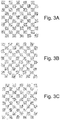
- Figures 2 and 3 illustrate the effect of such displacement errors on the representation of an exemplary wire mesh model and an exemplary checkerboard texture render pattern.
- Figure 2A is a plan view of an exemplary wire mesh model comprising a regular grid defining a flat surface.
- Figure 2B is a plan view of a reconstruction of the exemplary wire mesh model of Figure 2A from compressed data illustrating the introduction of small displacement errors such as arise in the encoding and compression processes. As can be seen in this illustration encoding introduces minor errors into the geometry data for the grid.
- Figure 3A is a representation of a rendering of a checker board pattern onto the surface of Figure 2A
- Figure 3B is a representation of the rendering of the same checker board pattern of Figure 3A on the surface of Figure 2B .
- the present invention identifies the spatial errors arising during mesh compression and encoding and then utilizes the identified errors to adjust the texture co-ordinate data 19 to be associated with a compressed model to compensate for such errors.
- Such correction may either be utilized to achieve a more accurate and faithful rendition of the original model or alternatively the modified texture co-ordinates may be subjected to truncation and approximation enabling higher rates of data compression to be achieved.
- original uncompressed texture co-ordinates might be represented by a pair of 4-byte (32-bit) floating point precision integers, they might be truncated to a pair of 2-byte (16-bit) integers, resulting in substantially reduced storage and transmission costs.
- any such truncation approximation of uv texture co-ordinates would be additive to errors from spatial distortion.
- processing the texture co-ordinates in advance to correct for the errors arising due to spatial distortions arising from mesh encoding and compression greater levels of truncation can be permitted for a permitted level of error.
- the co-ordinate modification module 3 is invoked when the encoding/decoding module 5 has finished processing the mesh data 15.
- the co-ordinate modification module 3 receives (s4-1) mesh data 15 and texture co-ordinate data 19 from the data store 7 and modified mesh data from the encoding/decoding module 5.
- Both the original mesh data 15 received from the data store 7 and the modified mesh data received from the encoding/decoding module 5 comprise data defining the 3D locations of vertices in the wire mesh being modeled.
- the original mesh data 15 received from the data store 7 will identify the positions of the vertices as they are recorded in the original mesh data 15.
- the modified mesh data received from the encoding/decoding module 5 will identify the locations of the vertices as they are represented in model data which is to be reconstructed from data output by the data transmission module 13. As noted above due to approximations in the encoding process the locations associated with corresponding vertices in the original and modified mesh data will differ slightly from one another.
- the co-ordinate modification module 3 then (s4-2) proceeds to calculate a set of positional error correction vectors.
- the co-ordinate modification module 3 proceeds to compare the 3D co-ordinates for each vertex in the wire mesh model as defined in the original mesh data 15 with the 3D co-ordinates for the corresponding vertex in the modified mesh data which is to be output by the data transmission module 13. The co-ordinate modification module 3 then records an error vector for each vertex recording the difference in position for the vertex as defined by the original mesh data 15 and the position for the vertex to be output by the data transmission module 13.
- the co-ordinate modification module 3 When error vectors have been determined for all of the vertices in the mesh being processed, the co-ordinate modification module 3 then (s4-3) checks whether the projection linking positions in 3D space and positions of point in the texture data 17 are known. If this is the case the co-ordinate modification module 3 then proceeds to utilize the projection and the error vectors to modify the texture co-ordinate data 19 received from the data store 7 so that the texture co-ordinate data 19 identify parts of the texture data 17 corresponding to the actual positions of vertices as identified by data output by the data transmission module 13 rather than the positions of vertices identified by the mesh data 15 in the data store 7.
- the 3D position of a second point in a wire mesh model P 2 is encoded by storing data defining the vector connecting a previously encoded point P 1 with the point being encoded P 2 (i.e. data recording the vector P 2 - P 1 is recorded).
- data for a modified vector is P' 2 - P 1 may be encoded in the data which is finally output with the result that the point is encoded as being at position P' 2 rather than position P 2 .
- point P 2 will be associated with a position T(u,v) in the image defined by the texture data 17.
- the output mesh data associates the vertex being encoded with P' 2 rather than position P 2
- the correct texture co-ordinates for the position actually being encoded will be at a different location T'(u,v) in the image defined by the texture data 17 with the location of T'(u,v) being offset from T(u,v) by a texture co-ordinate error vector ⁇ .
- the correction vector ⁇ in the image plane can be determined directly from the error vector ⁇ in 3D space by noting the projection of the error vector ⁇ into the image plane.
- the texture co-ordinates for the actual position identified by the output mesh data can then be determined by applying the correction ⁇ in the image plane to the original texture mesh co-ordinates T(u,v) so that texture applied to the point corresponding to texture at position T'(u,v) rather than T(u,v).
- Texture may be projected onto a surface in a vast number of ways. However, it is most common that some form of planar projection is used where texture data 17 is effectively projected onto a model in the manner of a slide projector onto a 3D surface from a particular direction with other more complex projections such as spherical or distorted projections being less common. It is therefore often possible if the projection in question is not known to determine a projection by (s4-5) analyzing the relationships between the 3D positions of vertices in the mesh data 15 and the u,v positions identified by texture co-ordinates 17 received from the data store 7. This can be achieved by analyzing the manner in which u,v co-ordinates vary depending upon variations in 3D position.
- a frequently used projection in the case of an elevation mesh where mesh vertices are arranged on a regular 2D grid is to use a projection where texture data 17 is effectively projected onto a surface from a plane lying parallel to the x and y axes.
- the existence of such a projection can be identified by considering the manner in which u,v positions vary dependent upon variations in x,y,z position data. In such an example, it would be possible to determine that for example u values varied monotonically with variations in x co-ordinate, v values varied monotonically with variations in y co-ordinate and no pattern of variation in z co-ordinate was apparent. Whereas a simple planar projection in the manner described is particularly easy to identify it will be appreciated that by comparing identified correlations between changes in 3D position and u,v texture co-ordinates other more complex projections can be identified.
- modified texture co-ordinates can then (s4-7) be calculated in a similar manner as has previously been described (s4-4) using the calculated error vectors ⁇ and the determined projection.
- Figure 4B illustrates the processing undertaken by the co-ordinate modification module 3 in this embodiment to determine an estimate.
- the co-ordinate modification module 3 determines an estimate of the corrections to be made based on the fact that the texture applied to individual triangles in a triangle mesh model are identified by the texture co-ordinates associated with the vertices of each of the triangles in the mesh.
- the co-ordinate modification module 3 selects a first triangle for processing and then selects (s4-9) an initial vertex from that triangle.
- the actual 3D position of the selected vertex as identified in the modified mesh data received from the encoding/decoding module 5 is then (s4-10) considered.
- the co-ordinate modification module 3 identifies the point in the texture data 17 corresponding to the output vertex location and records co-ordinate data for that point as a potential texture co-ordinate data for the vertex.
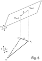
- the co-ordinate modification module 3 determines a projection of the output of the vertex being considered onto the plane containing the original locations of vertices of the triangle currently being processed.
- the triangle being processed is associated with original mesh data 15 which identifies the vertices of the triangle as being at points P 1 , P 2 , and P 3
- these basis vectors are P 2 -P 1 , P 3 -P 1 and ( P 2 -P 1 ) x( P 3 -P 1 ), where the origin for the basis vectors is chosen from a vertex of the triangle, typically as P 1 .
- a projection of a vertex as identified in output data on to the plane containing points P 1 , P 2 , and P 3 can then be made by representing the position of the vertex in the co-ordinate system of the three basis vectors and then setting the co-ordinate value for the final basis vector ( P 2 -P 1 ) x ( P 3 -P 1 ) to zero. This will then identify a point in the plane containing the triangle P 1 , P 2 , and P 3 .
- Estimated texture co-ordinates for the projection of the output position of a vertex into the plane containing the triangle being processed can then be determined by considering the mapping of texture co-ordinates to the plane containing points P 1 , P 2 , and P 3 defined by the original texture co-ordinate data 19 associated with the triangle being processed.
- the co-ordinate modification module 3 then checks (s4-11) whether texture co-ordinates for the actual positions for all three vertices of the triangle currently being process have been determined. If this is not the case, the next vertex in the triangle being processed is selected (s4-12) and estimated texture co-ordinates for that vertex are determined (s4-10).
- the co-ordinate modification module 3 determines (s4-11) that estimated texture co-ordinates for all three vertices in a triangle have been calculated, the co-ordinate modification module 3 then (s4-13) checks whether all of the triangles on the triangle mesh have been processed.
- the co-ordinate modification module 3 then proceeds (s4-9-s4-12) to generate estimated texture co-ordinates for all three vertices in the newly selected triangle.
- the co-ordinate modification module 3 determines (s4-13) that all the triangles in a triangle mesh have been processed, a set of estimated texture co-ordinates will be stored for each vertex in the mesh. This will comprise a pair of estimated texture co-ordinates for a vertex for each triangle in the triangle mesh containing that vertex. Thus for example if a particular vertex is shared by three triangles, three sets of estimated texture co-ordinates will be stored.
- the co-ordinate modification module 3 determines a final estimated modified texture co-ordinate for each vertex by, in this embodiment, taking an average of the estimated u,v co-ordinates determined for that vertex.
- the co-ordinate modification module 3 will have calculated a modified set of texture co-ordinate data 19 which accounts for the introduction of spatial errors in the encoding a compression of the mesh by the encoding/decoding module 5 and the compression module 11.
- These modified co-ordinates may have been determined based on a known relationship between texture render data 17 and positions in 3D model space (s4-4).
- modified texture co-ordinates may be based on the identification of a relationship between texture render data 17 and positions in 3D model space derived from analysis of mesh data 15 and unmodified texture co-ordinate data 19 (s4-7) or alternatively they may be based on estimates of modified texture co-ordinates based on the projection of points to planes containing triangles in the triangle mesh (s4-8 -s4-15).
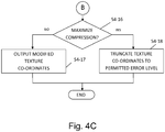
- the co-ordinate modification module 3 determines whether these modified texture co-ordinates are to be utilized to reduce the appearance of distortion of a texture rendered mesh or whether the modified texture co-ordinates are to be utilized to achieve improved level of data compression.
- the co-ordinate modification module 3 determines that the modified texture co-ordinates are to be utilized to reduce the appearance of distortion of a texture rendered mesh
- the modified texture co-ordinates are output (s4-17) to the compression/ decompression module 11 for compression using conventional techniques before compressed mesh data 15, texture data 17 and texture co-ordinate data 19 are passed to the data transmission module 13.
- the modification of texture co-ordinates in this way removes some of the errors which appear due to the encoding and compression of a mesh surface and hence improve the fidelity of a surface being rendered.
- the co-ordinate modification module 3 determines that the modified texture co-ordinates are to be utilized to achieve improved level of data compression, the co-ordinate modification module 3 proceeds (s4-18) to reduce the volume of the modified texture co-ordinates by truncating each item of co-ordinate data prior to sending the truncated modified texture co-ordinates to the compression/decompression module 11 for compression and dispatch by the data transition module 13.
- an error value representative of the apparent distortion of a model was determined. More specifically to evaluate the system, two dimensional distance values were calculated for the distance in u,v space between the exact corrected texture co-ordinates calculated for each vertex of an exemplary model and the position in u,v, coordinate space identified by either unmodified texture co-ordinate data or a position identified after texture co-ordinates had been truncated to a certain degree.
- An overall error value for the exemplary model was then calculated by summing the calculated distance measures for all of the vertices of the model resulting in the following: Total error value Original texture co-ordinates with 23 bits after the binary radix point 14.961 Modified texture co-ordinates with 23 bits after the binary radix point 0.046 Modified texture co-ordinates truncated to 18 bits after the binary radix point 0.066 Modified texture co-ordinates truncated to 14 bits after the binary radix point 0.753 Modified texture co-ordinates truncated to 10 bits after the binary radix point 12.057 Modified texture co-ordinates truncated to 9 bits after the binary radix point 24.079
- texture co-ordinates can be truncated to around 9-10 bits after the binary radix point before errors similar to those which arise in conventional unprocessed data re-appear.
- texture co-ordinate data is stored as a pair of 4 byte, 32-bit floating point precision integers for each vertex in a triangle mesh.
- Such co-ordinate data can account for around three quarters of the data needed to represent a texture rendered wire mesh model. Truncation of such data can result in significant levels of data compression. Thus for example in the case of an exemplary mesh the following were achieved.
- File size after compression Error Original data truncated to 15 bits after the binary radix point 78.2KB 14.98
- the embodiments of the invention described with reference to the drawings comprise computer apparatus and processes performed in computer apparatus, the invention also extends to computer programs, particularly computer programs on or in a carrier, adapted for putting the invention into practice.
- the program may be in the form of source or object code or in any other form suitable for use in the implementation of the processes according to the invention.
- the carrier could be any entity or device capable of carrying the program.
- the carrier may comprise a storage medium, such as a ROM, for example a CD ROM or a semiconductor ROM, or a magnetic recording medium, for example a floppy disc or hard disk.
- a storage medium such as a ROM, for example a CD ROM or a semiconductor ROM, or a magnetic recording medium, for example a floppy disc or hard disk.
- the carrier may be a transmissible carrier such as an electrical or optical signal which may be conveyed via electrical or optical cable or by radio or other means.
- the carrier When a program is embodied in a signal which may be conveyed directly by a cable or other device or means, the carrier may be constituted by such cable or other device or means.
- the carrier may be an integrated circuit in which the program is embedded, the integrated circuit being adapted for performing, or for use in the performance of, the relevant processes.
Landscapes
- Engineering & Computer Science (AREA)
- Multimedia (AREA)
- Physics & Mathematics (AREA)
- General Physics & Mathematics (AREA)
- Theoretical Computer Science (AREA)
- Image Generation (AREA)
Claims (15)
- Computerimplementiertes Verfahren zur Verarbeitung von Netzdaten, welche die räumlichen Koordinaten in einem Koordinatenraum von Scheitelpunkten einer Netzoberfläche definieren, und Textur-Koordinatendaten, welche Scheitelpunkte einer Netzoberfläche mit Positionen in einem Bildraum eines Bildes, das auf die Netzoberfläche gerendert werden soll, assoziieren, wobei das Verfahren Folgendes umfasst:Bestimmen einer Abbildung zwischen dem Koordinatenraum der Netzdaten und dem Bildraum eines Bildes, das auf die Netzoberfläche gerendert werden soll (S4-3, S4-5, S4-6) ;wobei das Verfahren dadurch gekennzeichnet ist, dass es Folgendes umfasst:Bestimmen, für jeden der Scheitelpunkte der Netzoberfläche, die durch Netzdaten dargestellt wird, räumlicher Fehlervektoren, welche die Unterschiede zwischen räumlichen Koordinaten von Scheitelpunkten der Netzoberfläche, wie durch die Netzdaten definiert, und den räumlichen Koordinaten entsprechender Scheitelpunkte in einer Netzoberfläche, die aus einer codierten Darstellung der Netzdaten erzeugt wird, identifizieren (S4-2);undModifizieren von Textur-Koordinatendaten zum Assoziieren von Scheitelpunkten des Netzes mit Positionen im Bildraum, welche sich von den Positionen, die durch die unmodifizierten Textur-Koordinatendaten identifiziert werden, um Mengen unterscheiden, die einer Abbildung des bestimmten räumlichen Fehlervektors, der mit einem Scheitelpunkt assoziiert ist, in den Bildraum in Übereinstimmung mit der bestimmten Abbildung, entsprechen (S4-4, S4-7).
- Verfahren nach Anspruch 1, wobei das Bestimmen einer Abbildung zwischen Koordinatenraum und Bildraum das Identifizieren einer bekannten Abbildung zwischen dem Koordinatenraum der Netzdaten und Positionen in dem Bild, das auf die Netzoberfläche gerendert werden soll, umfasst (S4-3).
- Verfahren nach Anspruch 1, wobei das Bestimmen einer Abbildung zwischen dem Koordinatenraum und dem Bildraum das Analysieren der räumlichen Koordinaten von Scheitelpunkten der Netzoberfläche in dem Koordinatenraum und der Textur-Koordinatendaten, welche Scheitelpunkte des Netzes mit Positionen in dem Bild, das auf die Netzoberfläche gerendert werden soll, assoziieren, umfasst, um eine Abbildung zwischen dem Koordinatenraum der Netzdaten und dem Bildraum des Bildes, das auf die Netzoberfläche gerendert werden soll, zu bestimmen (S4-5).
- Verfahren nach Anspruch 3, wobei die Analyse von räumlichen Koordinaten und Textur-Koordinatendaten das Identifizieren von Korrelationen zwischen Variationen in räumlichen Koordinaten von Scheitelpunkten, die durch Netzdaten identifiziert werden, und Bildpositionen, die durch Koordinatendaten mit den Scheitelpunkten assoziiert werden, umfasst, um eine Abbildung zwischen dem Koordinatenraum und dem Bildraum zu bestimmen.
- Verfahren nach Anspruch 4, wobei die Abbildung eine planare Abbildung umfasst und die Analyse von räumlichen Koordinaten und Textur-Koordinatendaten das Ausnutzen der identifizierten Korrelationen zum Bestimmen der planaren Abbildung umfasst.
- Verfahren nach Anspruch 1, wobei das Bestimmen einer Abbildung zwischen Koordinatenraum und Bildraum für jeden Scheitelpunkt in der Netzoberfläche Folgendes umfasst:Identifizieren einer Ebene im Koordinatenraum, welche die Scheitelpunkte eines Vielecks in dem Netz, welches den Scheitelpunkt beinhaltet, enthält;Bestimmen einer Projektion der räumlichen Position eines entsprechenden Scheitelpunktes in der Netzoberfläche, die aus einer codierten Darstellung der Netzdaten erzeugt wird, auf die identifizierte Ebene (S4-10); undSchätzen von modifizierten Textur-Koordinaten für den Scheitelpunkt auf der Grundlage der bestimmten Projektion auf die identifizierte Ebene und der Textur-Koordinaten, die mit den Scheitelpunkten des Vielecks assoziiert sind, welches die Ebene definiert (S4-15).
- Verfahren nach Anspruch 6, wobei das Bestimmen einer Abbildung zwischen Koordinatenraum und Bildraum Folgendes umfasst:Schätzen modifizierter Textur-Koordinaten für jeden Scheitelpunkt für jedes Vieleck, welches den Scheitelpunkt beinhaltet; undAusnutzen, als modifizierte Textur-Koordinaten, der durchschnittlichen Textur-Koordinaten, die für einen Scheitelpunkt bestimmt werden.
- Verfahren nach Anspruch 1, welches ferner das Kürzen der modifizierten Textur-Koordinaten umfasst (S4-18).
- Verfahren nach Anspruch 1, wobei die Netzdaten Dreiecksnetzdaten umfassen und wobei das Codieren von Dreiecken in dem Netz das Erzeugen von Daten, welche die relativen Positionen von Dreiecken definieren, und das Runden von Daten, welche die Dreiecke darstellen, auf innerhalb einer geometrischen Toleranz umfasst.
- Verfahren nach Anspruch 9, wobei das Codieren PRC-HCT-Codierung umfasst.
- Datenverarbeitungsvorrichtung (1), welche Folgendes umfasst:
einen Datenspeicher (7), der zum Speichern von Netzdaten (15), welche die räumlichen Koordinaten von Scheitelpunkten einer Netzoberfläche in einem Koordinatenraum definieren, und Textur-Koordinatendaten (17), welche Scheitelpunkte der Netzoberfläche mit Positionen in einem Bildraum eines Bildes, das auf die Netzoberfläche gerendert werden soll, assoziieren, geeignet ist; wobei die Vorrichtung ein Koordinatenmodifikationsmodul (3) umfasst, das zu Folgendem geeignet ist:Bestimmen einer Abbildung zwischen dem Koordinatenraum der Netzdaten und dem Bildraum eines Bildes, das auf die Netzoberfläche gerendert werden soll;wobei die Vorrichtung dadurch gekennzeichnet ist, dass das Koordinatenmodifikationsmodul (3) zu Folgendem geeignet ist:Bestimmen räumlicher Fehlervektoren, welche die Unterschiede zwischen räumlichen Koordinaten von Scheitelpunkten der Netzoberfläche, wie durch gespeicherte Netzdaten definiert, und den räumlichen Koordinaten entsprechender Scheitelpunkte in einer Netzoberfläche, die aus einer codierten Darstellung der Netzdaten erzeugt wird, identifizieren;undModifizieren gespeicherter Textur-Koordinatendaten zum Assoziieren von Scheitelpunkten eines Netzes, das durch Netzdaten definiert wird, die in dem Datenspeicher gespeichert sind, mit Positionen im Bildraum eines Bildes, das auf das Netz gerendert werden soll, welche sich von den Positionen, die durch die unmodifizierten Textur-Koordinatendaten identifiziert werden, um Mengen unterscheiden, welche der Abbildung des bestimmten räumlichen Fehlervektors, der mit einem Scheitelpunkt assoziiert ist, in den Bildraum in Übereinstimmung mit der bestimmten Abbildung zwischen dem Koordinatenraum und dem Bildraum entsprechen. - Datenverarbeitungsvorrichtung nach Anspruch 11, wobei das Koordinatenmodifikationsmodul (3) zum Implementieren des Computerverfahrens nach einem der Ansprüche 1 bis 10 geeignet ist.
- Datenverarbeitungsvorrichtung nach Anspruch 11 oder 12, welche ferner ein Codierungsmodul (5) umfasst, welches zum Codieren von Dreiecksnetzdaten geeignet ist, wobei das Codieren von Dreiecken in dem Netz das Erzeugen von Daten, welche die relativen Positionen von Dreiecken definieren, und das Runden von Daten, welche die Dreiecke darstellen, auf innerhalb einer geometrischen Toleranz umfasst.
- Datenverarbeitungsvorrichtung nach Anspruch 13, welche ferner ein Datenkomprimierungsmodul (11) umfasst, welches zum Komprimieren codierter Dreiecksnetzdaten, die durch das Codierungsmodul erzeugt werden, und zum Modifizieren von Textur-Koordinatendaten, die durch das Koordinatenmodifikationsmodul ausgegeben werden, geeignet ist.
- Nicht-transientes computerlesbares Medium, auf welchem computerimplementierbare Anweisungen gespeichert sind, welche, wenn sie durch einen programmierbaren Computer ausgeführt werden, den Computer zum Ausführen der Schritte des Verfahrens nach einem der Ansprüche 1 bis 10 veranlassen.
Applications Claiming Priority (1)
| Application Number | Priority Date | Filing Date | Title |
|---|---|---|---|
| US13/287,472 US8736603B2 (en) | 2011-11-02 | 2011-11-02 | Compression of texture rendered wire mesh models |
Publications (3)
| Publication Number | Publication Date |
|---|---|
| EP2592596A2 EP2592596A2 (de) | 2013-05-15 |
| EP2592596A3 EP2592596A3 (de) | 2014-12-24 |
| EP2592596B1 true EP2592596B1 (de) | 2020-04-15 |
Family
ID=47278080
Family Applications (1)
| Application Number | Title | Priority Date | Filing Date |
|---|---|---|---|
| EP12188600.6A Active EP2592596B1 (de) | 2011-11-02 | 2012-10-15 | Kompression texturdargestellter Drahtmaschenmodelle |
Country Status (2)
| Country | Link |
|---|---|
| US (1) | US8736603B2 (de) |
| EP (1) | EP2592596B1 (de) |
Families Citing this family (31)
| Publication number | Priority date | Publication date | Assignee | Title |
|---|---|---|---|---|
| US9251116B2 (en) * | 2011-11-30 | 2016-02-02 | International Business Machines Corporation | Direct interthread communication dataport pack/unpack and load/save |
| JP2015512072A (ja) * | 2012-01-21 | 2015-04-23 | トムソン ライセンシングThomson Licensing | 3次元(3d)モデルのテクスチャ情報を圧縮する方法及び装置 |
| US20140340393A1 (en) * | 2012-02-03 | 2014-11-20 | Thomson Licensing | System and method for error controllable repetitive structure discovery based compression |
| WO2013123635A1 (en) * | 2012-02-20 | 2013-08-29 | Thomson Licensing | Methods for compensating decoding error in three-dimensional models |
| KR101958844B1 (ko) * | 2012-04-18 | 2019-03-18 | 인터디지탈 매디슨 페이튼트 홀딩스 | 3d 모델을 표현하는 비트스트림을 생성 또는 디코딩하기 위한 방법 및 장치 |
| JP6246233B2 (ja) * | 2013-01-10 | 2017-12-13 | トムソン ライセンシングThomson Licensing | 頂点誤差訂正のための方法および装置 |
| US11122251B2 (en) | 2014-09-03 | 2021-09-14 | Apple Inc. | Methods and apparatus for receiving and/or playing back content |
| FR3028990B1 (fr) * | 2014-11-21 | 2018-01-19 | Institut National Des Sciences Appliquees De Lyon | Procedes de compression et de decompression de donnees representatives d’un objet tridimensionnel numerique et support d'enregistrement d'informations contenant ces donnees |
| US9646410B2 (en) | 2015-06-30 | 2017-05-09 | Microsoft Technology Licensing, Llc | Mixed three dimensional scene reconstruction from plural surface models |
| US10163247B2 (en) | 2015-07-14 | 2018-12-25 | Microsoft Technology Licensing, Llc | Context-adaptive allocation of render model resources |
| US9665978B2 (en) * | 2015-07-20 | 2017-05-30 | Microsoft Technology Licensing, Llc | Consistent tessellation via topology-aware surface tracking |
| US10313673B2 (en) | 2016-10-19 | 2019-06-04 | Google Llc | Methods and apparatus to encode and/or decode normals of geometric representations of surfaces |
| US10733766B2 (en) | 2016-10-19 | 2020-08-04 | Google, Llc | Methods and apparatus to encode and/or decode normals of geometric representations of surfaces |
| US10496336B2 (en) | 2016-11-17 | 2019-12-03 | Google Llc | K-D tree encoding for point clouds using deviations |
| US9787321B1 (en) | 2016-11-17 | 2017-10-10 | Google Inc. | Point cloud data compression using a space-filling curve |
| US10430975B2 (en) | 2016-11-17 | 2019-10-01 | Google Llc | Advanced k-D tree encoding for point clouds by most significant axis selection |
| US10950042B2 (en) | 2017-06-02 | 2021-03-16 | Google Llc | Guided traversal in compression of triangular meshes |
| US10553035B2 (en) | 2017-06-02 | 2020-02-04 | Google Llc | Valence based implicit traversal for improved compression of triangular meshes |
| US10650586B2 (en) * | 2017-08-10 | 2020-05-12 | Outward, Inc. | Automated mesh generation |
| CN109544668B (zh) * | 2017-09-21 | 2022-10-25 | 腾讯科技(深圳)有限公司 | 纹理坐标处理方法、终端设备及计算机可读存储介质 |
| US10417806B2 (en) * | 2018-02-15 | 2019-09-17 | JJK Holdings, LLC | Dynamic local temporal-consistent textured mesh compression |
| US10891758B2 (en) | 2018-07-23 | 2021-01-12 | Google Llc | Geometry encoder |
| CN111773707A (zh) * | 2020-08-11 | 2020-10-16 | 网易(杭州)网络有限公司 | 一种渲染处理的方法及装置、电子设备、存储介质 |
| EP3995984B1 (de) * | 2020-11-05 | 2024-12-18 | Dassault Systemes Deutschland GmbH | Hüllen für zellbasierte dreidimensionale modelle durch schrumpfung |
| CN112365584B (zh) * | 2020-11-23 | 2024-05-31 | 浙江凌迪数字科技有限公司 | 一种在三维服装模型上生成印花效果的方法 |
| JP2024520211A (ja) * | 2021-05-25 | 2024-05-22 | ヨーム.コム リミテッド | ウェブブラウザのボリュメトリックビデオ |
| US12493993B2 (en) | 2022-01-10 | 2025-12-09 | Tencent America LLC | Mesh compression with deduced texture coordinates |
| CN117412058A (zh) * | 2022-07-06 | 2024-01-16 | 维沃移动通信有限公司 | 编码、解码方法、装置及设备 |
| CN115641396A (zh) * | 2022-10-10 | 2023-01-24 | 浙江大学 | 一种适用于三维游戏与虚拟现实应用的纹理图像优化方法 |
| US12548202B2 (en) * | 2022-10-21 | 2026-02-10 | Tencent America LLC | Texture coordinate compression using chart partition |
| CN118803256A (zh) * | 2023-04-14 | 2024-10-18 | 西安光锥视象科技有限公司 | 一种三维网格序列编解码方法及装置 |
Family Cites Families (15)
| Publication number | Priority date | Publication date | Assignee | Title |
|---|---|---|---|---|
| US5953506A (en) * | 1996-12-17 | 1999-09-14 | Adaptive Media Technologies | Method and apparatus that provides a scalable media delivery system |
| US6064771A (en) * | 1997-06-23 | 2000-05-16 | Real-Time Geometry Corp. | System and method for asynchronous, adaptive moving picture compression, and decompression |
| US6208347B1 (en) * | 1997-06-23 | 2001-03-27 | Real-Time Geometry Corporation | System and method for computer modeling of 3D objects and 2D images by mesh constructions that incorporate non-spatial data such as color or texture |
| JP4384813B2 (ja) * | 1998-06-08 | 2009-12-16 | マイクロソフト コーポレーション | 時間依存ジオメトリの圧縮 |
| WO2003075116A2 (en) * | 2002-03-01 | 2003-09-12 | T5 Labs Ltd | Centralised interactive graphical application server |
| WO2003088085A1 (en) * | 2002-04-04 | 2003-10-23 | Arizona Board Of Regents | Three-dimensional digital library system |
| US7436981B2 (en) * | 2005-01-28 | 2008-10-14 | Euclid Discoveries, Llc | Apparatus and method for processing video data |
| DE102004049156B4 (de) * | 2004-10-08 | 2006-07-13 | Fraunhofer-Gesellschaft zur Förderung der angewandten Forschung e.V. | Codierschema für einen ein zeitlich veränderliches Graphikmodell darstellenden Datenstrom |
| US7432936B2 (en) * | 2004-12-02 | 2008-10-07 | Avid Technology, Inc. | Texture data anti-aliasing method and apparatus |
| US8207965B2 (en) * | 2006-07-11 | 2012-06-26 | Adobe Systems Incorporated | Rewritable compression of triangulated data |
| ATE554601T1 (de) * | 2007-04-18 | 2012-05-15 | Univ Hannover | Skalierbare komprimierung zeitkonsistenter 3d- netzwerksequenzen |
| EP2216750A1 (de) * | 2009-02-06 | 2010-08-11 | Thomson Licensing | Verfahren und Vorrichtung zum Kodieren dreidimensionaler Maschenmodelle und Verfahren und Vorrichtung zum Dekodieren kodierter dreidimensionaler Maschenmodelle |
| EP2261859A1 (de) * | 2009-06-10 | 2010-12-15 | Thomson Licensing | Verfahren zur Kodierung/Dekodierung eines dreidimensionalen Maschenmodells, das eine oder mehrere Komponenten umfasst |
| GB201003962D0 (en) * | 2010-03-10 | 2010-04-21 | Tangentix Ltd | Multimedia content delivery system |
| US8416236B1 (en) * | 2012-07-19 | 2013-04-09 | Google Inc. | Calibration of devices used to generate images of a three-dimensional object data model |
-
2011
- 2011-11-02 US US13/287,472 patent/US8736603B2/en active Active
-
2012
- 2012-10-15 EP EP12188600.6A patent/EP2592596B1/de active Active
Non-Patent Citations (2)
| Title |
|---|
| JONATHAN COHEN ET AL: "Simplifying polygonal models using successive mappings", VISUALIZATION '97, IEEE COMPUTER SOCIETY PRESS, 10662 LOS VAQUEROS CIRCLE PO BOX 3014 LOS ALAMITOS, CA 90720-1264 USA, 1 October 1997 (1997-10-01), pages 395 - ff, XP058190414, ISBN: 978-1-58113-011-9 * |
| MICHAEL S FLOATER1 AND KAI HORMANN2: "Surface Parameterization: a Tutorial and Survey", INTERNET CITATION, 1 January 2005 (2005-01-01), pages 157 - 186, XP008129791, Retrieved from the Internet <URL:http://vcg.isti.cnr.it/Publications/2005/FH05/> [retrieved on 20101126] * |
Also Published As
| Publication number | Publication date |
|---|---|
| US20130106834A1 (en) | 2013-05-02 |
| EP2592596A3 (de) | 2014-12-24 |
| EP2592596A2 (de) | 2013-05-15 |
| US8736603B2 (en) | 2014-05-27 |
Similar Documents
| Publication | Publication Date | Title |
|---|---|---|
| EP2592596B1 (de) | Kompression texturdargestellter Drahtmaschenmodelle | |
| CN113939849B (zh) | 经由点云表示的网格压缩 | |
| US7113635B2 (en) | Process for modelling a 3D scene | |
| JP6676193B2 (ja) | シーンを表す点群を符号化する方法、符号化器システム、及びプログラムを記憶した非一時的コンピューター可読記録媒体 | |
| JP6501240B2 (ja) | 点群を圧縮する方法 | |
| EP0841636B1 (de) | Verfahren und Vorrichtung zur Eingabe und Ausgabe von Farb- und Grantonbildern | |
| CN113302940B (zh) | 使用单应性变换的点云编码 | |
| EP0649260A2 (de) | Bilddatenvorstellungs- und -wiederherstellungsverfahren | |
| US12536710B2 (en) | Dynamic mesh coding with simplified topology | |
| CN112970246A (zh) | 视图合成 | |
| CN116848553A (zh) | 基于二维uv地图集采样的用于动态网格压缩的方法 | |
| CN116664754A (zh) | 编码方法、装置及设备 | |
| JP4672735B2 (ja) | 効果的なテクスチャマッピングのための3次元メッシュ情報のテクスチャ座標符号化及び復号化方法 | |
| US12315081B2 (en) | Mesh patch sub-division | |
| HK1182208B (en) | Compression of texture rendered wire mesh models | |
| EP4233006B1 (de) | Geräte und methoden für die örtliche quantisierung einer punktwolkenkomprimierung | |
| US12412313B2 (en) | Mesh geometry coding | |
| CN116458158B (zh) | 帧内预测方法及装置、编解码器、设备、存储介质 | |
| HK1182208A (en) | Compression of texture rendered wire mesh models | |
| EP4479938A1 (de) | Netzgeometriecodierung | |
| WO2024255912A1 (en) | Encoding method, decoding method, bitstream, encoder, decoder, medium and program product | |
| CN118302794A (zh) | 网格几何编码 | |
| CN118541732A (zh) | 使用简化的拓扑的动态网格编码 | |
| CN121639835A (zh) | 一种三维网格数据处理方法及装置 | |
| Imre et al. | Rate-distortion efficient piecewise planar 3-D scene representation from 2-D images |
Legal Events
| Date | Code | Title | Description |
|---|---|---|---|
| PUAI | Public reference made under article 153(3) epc to a published international application that has entered the european phase |
Free format text: ORIGINAL CODE: 0009012 |
|
| AK | Designated contracting states |
Kind code of ref document: A2 Designated state(s): AL AT BE BG CH CY CZ DE DK EE ES FI FR GB GR HR HU IE IS IT LI LT LU LV MC MK MT NL NO PL PT RO RS SE SI SK SM TR |
|
| AX | Request for extension of the european patent |
Extension state: BA ME |
|
| REG | Reference to a national code |
Ref country code: HK Ref legal event code: DE Ref document number: 1182208 Country of ref document: HK |
|
| PUAL | Search report despatched |
Free format text: ORIGINAL CODE: 0009013 |
|
| RIC1 | Information provided on ipc code assigned before grant |
Ipc: G06T 9/00 20060101AFI20141111BHEP |
|
| AK | Designated contracting states |
Kind code of ref document: A3 Designated state(s): AL AT BE BG CH CY CZ DE DK EE ES FI FR GB GR HR HU IE IS IT LI LT LU LV MC MK MT NL NO PL PT RO RS SE SI SK SM TR |
|
| AX | Request for extension of the european patent |
Extension state: BA ME |
|
| 17P | Request for examination filed |
Effective date: 20150623 |
|
| STAA | Information on the status of an ep patent application or granted ep patent |
Free format text: STATUS: EXAMINATION IS IN PROGRESS |
|
| 17Q | First examination report despatched |
Effective date: 20170524 |
|
| RAP1 | Party data changed (applicant data changed or rights of an application transferred) |
Owner name: VISUAL TECHNOLOGY SERVICES LTD. |
|
| GRAP | Despatch of communication of intention to grant a patent |
Free format text: ORIGINAL CODE: EPIDOSNIGR1 |
|
| STAA | Information on the status of an ep patent application or granted ep patent |
Free format text: STATUS: GRANT OF PATENT IS INTENDED |
|
| INTG | Intention to grant announced |
Effective date: 20191113 |
|
| RIN1 | Information on inventor provided before grant (corrected) |
Inventor name: CURINGTON, IAN |
|
| GRAS | Grant fee paid |
Free format text: ORIGINAL CODE: EPIDOSNIGR3 |
|
| GRAA | (expected) grant |
Free format text: ORIGINAL CODE: 0009210 |
|
| STAA | Information on the status of an ep patent application or granted ep patent |
Free format text: STATUS: THE PATENT HAS BEEN GRANTED |
|
| AK | Designated contracting states |
Kind code of ref document: B1 Designated state(s): AL AT BE BG CH CY CZ DE DK EE ES FI FR GB GR HR HU IE IS IT LI LT LU LV MC MK MT NL NO PL PT RO RS SE SI SK SM TR |
|
| REG | Reference to a national code |
Ref country code: CH Ref legal event code: EP Ref country code: GB Ref legal event code: FG4D |
|
| REG | Reference to a national code |
Ref country code: DE Ref legal event code: R096 Ref document number: 602012069266 Country of ref document: DE |
|
| REG | Reference to a national code |
Ref country code: IE Ref legal event code: FG4D |
|
| REG | Reference to a national code |
Ref country code: AT Ref legal event code: REF Ref document number: 1258173 Country of ref document: AT Kind code of ref document: T Effective date: 20200515 |
|
| REG | Reference to a national code |
Ref country code: SE Ref legal event code: TRGR |
|
| REG | Reference to a national code |
Ref country code: NL Ref legal event code: FP |
|
| REG | Reference to a national code |
Ref country code: CH Ref legal event code: NV Representative=s name: KIRKER AND CIE S.A., CH |
|
| REG | Reference to a national code |
Ref country code: LT Ref legal event code: MG4D |
|
| PG25 | Lapsed in a contracting state [announced via postgrant information from national office to epo] |
Ref country code: PT Free format text: LAPSE BECAUSE OF FAILURE TO SUBMIT A TRANSLATION OF THE DESCRIPTION OR TO PAY THE FEE WITHIN THE PRESCRIBED TIME-LIMIT Effective date: 20200817 Ref country code: NO Free format text: LAPSE BECAUSE OF FAILURE TO SUBMIT A TRANSLATION OF THE DESCRIPTION OR TO PAY THE FEE WITHIN THE PRESCRIBED TIME-LIMIT Effective date: 20200715 Ref country code: IS Free format text: LAPSE BECAUSE OF FAILURE TO SUBMIT A TRANSLATION OF THE DESCRIPTION OR TO PAY THE FEE WITHIN THE PRESCRIBED TIME-LIMIT Effective date: 20200815 Ref country code: FI Free format text: LAPSE BECAUSE OF FAILURE TO SUBMIT A TRANSLATION OF THE DESCRIPTION OR TO PAY THE FEE WITHIN THE PRESCRIBED TIME-LIMIT Effective date: 20200415 Ref country code: LT Free format text: LAPSE BECAUSE OF FAILURE TO SUBMIT A TRANSLATION OF THE DESCRIPTION OR TO PAY THE FEE WITHIN THE PRESCRIBED TIME-LIMIT Effective date: 20200415 Ref country code: GR Free format text: LAPSE BECAUSE OF FAILURE TO SUBMIT A TRANSLATION OF THE DESCRIPTION OR TO PAY THE FEE WITHIN THE PRESCRIBED TIME-LIMIT Effective date: 20200716 |
|
| REG | Reference to a national code |
Ref country code: AT Ref legal event code: MK05 Ref document number: 1258173 Country of ref document: AT Kind code of ref document: T Effective date: 20200415 |
|
| PG25 | Lapsed in a contracting state [announced via postgrant information from national office to epo] |
Ref country code: LV Free format text: LAPSE BECAUSE OF FAILURE TO SUBMIT A TRANSLATION OF THE DESCRIPTION OR TO PAY THE FEE WITHIN THE PRESCRIBED TIME-LIMIT Effective date: 20200415 Ref country code: RS Free format text: LAPSE BECAUSE OF FAILURE TO SUBMIT A TRANSLATION OF THE DESCRIPTION OR TO PAY THE FEE WITHIN THE PRESCRIBED TIME-LIMIT Effective date: 20200415 Ref country code: BG Free format text: LAPSE BECAUSE OF FAILURE TO SUBMIT A TRANSLATION OF THE DESCRIPTION OR TO PAY THE FEE WITHIN THE PRESCRIBED TIME-LIMIT Effective date: 20200715 Ref country code: HR Free format text: LAPSE BECAUSE OF FAILURE TO SUBMIT A TRANSLATION OF THE DESCRIPTION OR TO PAY THE FEE WITHIN THE PRESCRIBED TIME-LIMIT Effective date: 20200415 |
|
| PG25 | Lapsed in a contracting state [announced via postgrant information from national office to epo] |
Ref country code: AL Free format text: LAPSE BECAUSE OF FAILURE TO SUBMIT A TRANSLATION OF THE DESCRIPTION OR TO PAY THE FEE WITHIN THE PRESCRIBED TIME-LIMIT Effective date: 20200415 |
|
| REG | Reference to a national code |
Ref country code: DE Ref legal event code: R097 Ref document number: 602012069266 Country of ref document: DE |
|
| PG25 | Lapsed in a contracting state [announced via postgrant information from national office to epo] |
Ref country code: IT Free format text: LAPSE BECAUSE OF FAILURE TO SUBMIT A TRANSLATION OF THE DESCRIPTION OR TO PAY THE FEE WITHIN THE PRESCRIBED TIME-LIMIT Effective date: 20200415 Ref country code: RO Free format text: LAPSE BECAUSE OF FAILURE TO SUBMIT A TRANSLATION OF THE DESCRIPTION OR TO PAY THE FEE WITHIN THE PRESCRIBED TIME-LIMIT Effective date: 20200415 Ref country code: CZ Free format text: LAPSE BECAUSE OF FAILURE TO SUBMIT A TRANSLATION OF THE DESCRIPTION OR TO PAY THE FEE WITHIN THE PRESCRIBED TIME-LIMIT Effective date: 20200415 Ref country code: EE Free format text: LAPSE BECAUSE OF FAILURE TO SUBMIT A TRANSLATION OF THE DESCRIPTION OR TO PAY THE FEE WITHIN THE PRESCRIBED TIME-LIMIT Effective date: 20200415 Ref country code: SM Free format text: LAPSE BECAUSE OF FAILURE TO SUBMIT A TRANSLATION OF THE DESCRIPTION OR TO PAY THE FEE WITHIN THE PRESCRIBED TIME-LIMIT Effective date: 20200415 Ref country code: AT Free format text: LAPSE BECAUSE OF FAILURE TO SUBMIT A TRANSLATION OF THE DESCRIPTION OR TO PAY THE FEE WITHIN THE PRESCRIBED TIME-LIMIT Effective date: 20200415 Ref country code: DK Free format text: LAPSE BECAUSE OF FAILURE TO SUBMIT A TRANSLATION OF THE DESCRIPTION OR TO PAY THE FEE WITHIN THE PRESCRIBED TIME-LIMIT Effective date: 20200415 Ref country code: ES Free format text: LAPSE BECAUSE OF FAILURE TO SUBMIT A TRANSLATION OF THE DESCRIPTION OR TO PAY THE FEE WITHIN THE PRESCRIBED TIME-LIMIT Effective date: 20200415 |
|
| PLBE | No opposition filed within time limit |
Free format text: ORIGINAL CODE: 0009261 |
|
| STAA | Information on the status of an ep patent application or granted ep patent |
Free format text: STATUS: NO OPPOSITION FILED WITHIN TIME LIMIT |
|
| PG25 | Lapsed in a contracting state [announced via postgrant information from national office to epo] |
Ref country code: PL Free format text: LAPSE BECAUSE OF FAILURE TO SUBMIT A TRANSLATION OF THE DESCRIPTION OR TO PAY THE FEE WITHIN THE PRESCRIBED TIME-LIMIT Effective date: 20200415 Ref country code: SK Free format text: LAPSE BECAUSE OF FAILURE TO SUBMIT A TRANSLATION OF THE DESCRIPTION OR TO PAY THE FEE WITHIN THE PRESCRIBED TIME-LIMIT Effective date: 20200415 |
|
| 26N | No opposition filed |
Effective date: 20210118 |
|
| PG25 | Lapsed in a contracting state [announced via postgrant information from national office to epo] |
Ref country code: SI Free format text: LAPSE BECAUSE OF FAILURE TO SUBMIT A TRANSLATION OF THE DESCRIPTION OR TO PAY THE FEE WITHIN THE PRESCRIBED TIME-LIMIT Effective date: 20200415 |
|
| PG25 | Lapsed in a contracting state [announced via postgrant information from national office to epo] |
Ref country code: LU Free format text: LAPSE BECAUSE OF NON-PAYMENT OF DUE FEES Effective date: 20201015 Ref country code: MC Free format text: LAPSE BECAUSE OF FAILURE TO SUBMIT A TRANSLATION OF THE DESCRIPTION OR TO PAY THE FEE WITHIN THE PRESCRIBED TIME-LIMIT Effective date: 20200415 |
|
| PG25 | Lapsed in a contracting state [announced via postgrant information from national office to epo] |
Ref country code: TR Free format text: LAPSE BECAUSE OF FAILURE TO SUBMIT A TRANSLATION OF THE DESCRIPTION OR TO PAY THE FEE WITHIN THE PRESCRIBED TIME-LIMIT Effective date: 20200415 Ref country code: MT Free format text: LAPSE BECAUSE OF FAILURE TO SUBMIT A TRANSLATION OF THE DESCRIPTION OR TO PAY THE FEE WITHIN THE PRESCRIBED TIME-LIMIT Effective date: 20200415 Ref country code: CY Free format text: LAPSE BECAUSE OF FAILURE TO SUBMIT A TRANSLATION OF THE DESCRIPTION OR TO PAY THE FEE WITHIN THE PRESCRIBED TIME-LIMIT Effective date: 20200415 |
|
| PG25 | Lapsed in a contracting state [announced via postgrant information from national office to epo] |
Ref country code: MK Free format text: LAPSE BECAUSE OF FAILURE TO SUBMIT A TRANSLATION OF THE DESCRIPTION OR TO PAY THE FEE WITHIN THE PRESCRIBED TIME-LIMIT Effective date: 20200415 |
|
| PGFP | Annual fee paid to national office [announced via postgrant information from national office to epo] |
Ref country code: NL Payment date: 20221012 Year of fee payment: 11 Ref country code: FR Payment date: 20221010 Year of fee payment: 11 |
|
| PGFP | Annual fee paid to national office [announced via postgrant information from national office to epo] |
Ref country code: SE Payment date: 20221017 Year of fee payment: 11 Ref country code: IE Payment date: 20221026 Year of fee payment: 11 Ref country code: GB Payment date: 20221007 Year of fee payment: 11 Ref country code: DE Payment date: 20221018 Year of fee payment: 11 |
|
| PGFP | Annual fee paid to national office [announced via postgrant information from national office to epo] |
Ref country code: CH Payment date: 20221014 Year of fee payment: 11 Ref country code: BE Payment date: 20221012 Year of fee payment: 11 |
|
| REG | Reference to a national code |
Ref country code: DE Ref legal event code: R119 Ref document number: 602012069266 Country of ref document: DE |
|
| REG | Reference to a national code |
Ref country code: SE Ref legal event code: EUG |
|
| REG | Reference to a national code |
Ref country code: CH Ref legal event code: PL |
|
| REG | Reference to a national code |
Ref country code: NL Ref legal event code: MM Effective date: 20231101 |
|
| REG | Reference to a national code |
Ref country code: BE Ref legal event code: MM Effective date: 20231031 |
|
| GBPC | Gb: european patent ceased through non-payment of renewal fee |
Effective date: 20231015 |
|
| PG25 | Lapsed in a contracting state [announced via postgrant information from national office to epo] |
Ref country code: GB Free format text: LAPSE BECAUSE OF NON-PAYMENT OF DUE FEES Effective date: 20231015 |
|
| PG25 | Lapsed in a contracting state [announced via postgrant information from national office to epo] |
Ref country code: CH Free format text: LAPSE BECAUSE OF NON-PAYMENT OF DUE FEES Effective date: 20231031 Ref country code: NL Free format text: LAPSE BECAUSE OF NON-PAYMENT OF DUE FEES Effective date: 20231101 |
|
| PG25 | Lapsed in a contracting state [announced via postgrant information from national office to epo] |
Ref country code: NL Free format text: LAPSE BECAUSE OF NON-PAYMENT OF DUE FEES Effective date: 20231101 Ref country code: GB Free format text: LAPSE BECAUSE OF NON-PAYMENT OF DUE FEES Effective date: 20231015 Ref country code: FR Free format text: LAPSE BECAUSE OF NON-PAYMENT OF DUE FEES Effective date: 20231031 Ref country code: DE Free format text: LAPSE BECAUSE OF NON-PAYMENT OF DUE FEES Effective date: 20240501 Ref country code: CH Free format text: LAPSE BECAUSE OF NON-PAYMENT OF DUE FEES Effective date: 20231031 |
|
| PG25 | Lapsed in a contracting state [announced via postgrant information from national office to epo] |
Ref country code: SE Free format text: LAPSE BECAUSE OF NON-PAYMENT OF DUE FEES Effective date: 20231016 Ref country code: BE Free format text: LAPSE BECAUSE OF NON-PAYMENT OF DUE FEES Effective date: 20231031 |
|
| PG25 | Lapsed in a contracting state [announced via postgrant information from national office to epo] |
Ref country code: IE Free format text: LAPSE BECAUSE OF NON-PAYMENT OF DUE FEES Effective date: 20231015 |
|
| PG25 | Lapsed in a contracting state [announced via postgrant information from national office to epo] |
Ref country code: IE Free format text: LAPSE BECAUSE OF NON-PAYMENT OF DUE FEES Effective date: 20231015 |