EP2592455A2 - Integrierte Leuchte - Google Patents
Integrierte Leuchte Download PDFInfo
- Publication number
- EP2592455A2 EP2592455A2 EP20120184718 EP12184718A EP2592455A2 EP 2592455 A2 EP2592455 A2 EP 2592455A2 EP 20120184718 EP20120184718 EP 20120184718 EP 12184718 A EP12184718 A EP 12184718A EP 2592455 A2 EP2592455 A2 EP 2592455A2
- Authority
- EP
- European Patent Office
- Prior art keywords
- illuminator
- fibre
- housing
- side emitting
- light
- Prior art date
- Legal status (The legal status is an assumption and is not a legal conclusion. Google has not performed a legal analysis and makes no representation as to the accuracy of the status listed.)
- Withdrawn
Links
Images




Classifications
-
- G—PHYSICS
- G02—OPTICS
- G02B—OPTICAL ELEMENTS, SYSTEMS OR APPARATUS
- G02B6/00—Light guides; Structural details of arrangements comprising light guides and other optical elements, e.g. couplings
- G02B6/24—Coupling light guides
- G02B6/36—Mechanical coupling means
- G02B6/38—Mechanical coupling means having fibre to fibre mating means
- G02B6/3807—Dismountable connectors, i.e. comprising plugs
- G02B6/381—Dismountable connectors, i.e. comprising plugs of the ferrule type, e.g. fibre ends embedded in ferrules, connecting a pair of fibres
- G02B6/3816—Dismountable connectors, i.e. comprising plugs of the ferrule type, e.g. fibre ends embedded in ferrules, connecting a pair of fibres for use under water, high pressure connectors
-
- G—PHYSICS
- G02—OPTICS
- G02B—OPTICAL ELEMENTS, SYSTEMS OR APPARATUS
- G02B6/00—Light guides; Structural details of arrangements comprising light guides and other optical elements, e.g. couplings
- G02B6/0001—Light guides; Structural details of arrangements comprising light guides and other optical elements, e.g. couplings specially adapted for lighting devices or systems
- G02B6/0005—Light guides; Structural details of arrangements comprising light guides and other optical elements, e.g. couplings specially adapted for lighting devices or systems the light guides being of the fibre type
- G02B6/0006—Coupling light into the fibre
-
- G—PHYSICS
- G02—OPTICS
- G02B—OPTICAL ELEMENTS, SYSTEMS OR APPARATUS
- G02B6/00—Light guides; Structural details of arrangements comprising light guides and other optical elements, e.g. couplings
- G02B6/0001—Light guides; Structural details of arrangements comprising light guides and other optical elements, e.g. couplings specially adapted for lighting devices or systems
- G02B6/0005—Light guides; Structural details of arrangements comprising light guides and other optical elements, e.g. couplings specially adapted for lighting devices or systems the light guides being of the fibre type
- G02B6/0008—Light guides; Structural details of arrangements comprising light guides and other optical elements, e.g. couplings specially adapted for lighting devices or systems the light guides being of the fibre type the light being emitted at the end of the fibre
-
- G—PHYSICS
- G02—OPTICS
- G02B—OPTICAL ELEMENTS, SYSTEMS OR APPARATUS
- G02B6/00—Light guides; Structural details of arrangements comprising light guides and other optical elements, e.g. couplings
- G02B6/24—Coupling light guides
- G02B6/42—Coupling light guides with opto-electronic elements
- G02B6/4201—Packages, e.g. shape, construction, internal or external details
- G02B6/4248—Feed-through connections for the hermetical passage of fibres through a package wall
-
- G—PHYSICS
- G02—OPTICS
- G02B—OPTICAL ELEMENTS, SYSTEMS OR APPARATUS
- G02B6/00—Light guides; Structural details of arrangements comprising light guides and other optical elements, e.g. couplings
- G02B6/24—Coupling light guides
- G02B6/36—Mechanical coupling means
- G02B6/38—Mechanical coupling means having fibre to fibre mating means
- G02B6/3807—Dismountable connectors, i.e. comprising plugs
- G02B6/389—Dismountable connectors, i.e. comprising plugs characterised by the method of fastening connecting plugs and sockets, e.g. screw- or nut-lock, snap-in, bayonet type
- G02B6/3891—Bayonet type
-
- G—PHYSICS
- G02—OPTICS
- G02B—OPTICAL ELEMENTS, SYSTEMS OR APPARATUS
- G02B6/00—Light guides; Structural details of arrangements comprising light guides and other optical elements, e.g. couplings
- G02B6/24—Coupling light guides
- G02B6/36—Mechanical coupling means
- G02B6/38—Mechanical coupling means having fibre to fibre mating means
- G02B6/3807—Dismountable connectors, i.e. comprising plugs
- G02B6/3897—Connectors fixed to housings, casing, frames or circuit boards
-
- G—PHYSICS
- G02—OPTICS
- G02B—OPTICAL ELEMENTS, SYSTEMS OR APPARATUS
- G02B6/00—Light guides; Structural details of arrangements comprising light guides and other optical elements, e.g. couplings
- G02B6/24—Coupling light guides
- G02B6/36—Mechanical coupling means
- G02B6/40—Mechanical coupling means having fibre bundle mating means
- G02B6/403—Mechanical coupling means having fibre bundle mating means of the ferrule type, connecting a pair of ferrules
Definitions
- the present invention is concerned with an optical light source or box for supplying light to a distributed illumination system based on side emitting optical fibre or fibre bundles.
- the source is adapted for use under adverse and challenging environmental conditions.
- the invention also relates to an integrated illuminator and in particular an integrated fibre based illuminator for use for illumination and/or communications.
- Side emitting fibres or fibre bundles can provide high intensity light at peak eye response, as well as light of other colours as required. They are particularly appropriate for use in hazardous environments, for example in chemical or oil refining plants, mines, wellheads, and oil-rig platforms, where illumination methodologies involving the supply of electrical power within the hazardous environments can lead to risk of explosions. They also lend themselves to use in underwater environments, for example, subsea and any inland water including lakes, rivers, lochs, harbours, docks, canals and all other types of waterways, including in aqua-culture, as well as in many other environmentally challenging situations. In addition, they are ideal for providing egress/guide-path lighting and safety lighting, for example for illuminating clear paths to exits. This results from the distributed and continuous nature of the source along the length of the fibre or fibre bundle. Furthermore, such sources can also serve the dual purpose of illumination and communication, where information is dispersed through appropriate modulation of the emitted light.
- an optical device comprising a housing; a light source and/or a detector within the housing; a window through the housing that is transparent to light transmitted from the light source or to the detector and a fixing for fixing an optical fibre or bundle of such fibres into a coupling position adjacent the window to allow light to pass between the housing and the fibre or fibre bundle.
- the fixing is such that it allows connection and disconnection of the fibre or fibre bundle without breaking seals to the housing or light box.
- Light generated within the housing is transmitted through an optical interface directly into the fibre(s).
- the use of an external fixing for securing the fibre or fibre bundle in place means that the light-box can be sealed for coupling and uncoupling to the optical fibre or fibre bundle. This means that the integrity of any optical, electronic or other components within the housing can be maintained.
- the fixing may hold the optical fibre or bundle of fibres in butt coupled contact with an external surface of the window.
- the fixing may be adapted to compress the fibre end against the window.
- the fixing may be adapted to mate with a fixing element on the fibre or fibre bundle.
- the fixing may comprise a male part and a female part, one being on the housing and the other being on the fibre or fibre bundle.
- the fixing may comprise a bayonet connector.
- a heat sink may be provided.
- a non-imaging light concentrator may be provided for directing light from the light source to the fibre and/or for the purpose of optimally coupling the light into the fibre.
- the non-imaging concentrator may be employed for directing light from the fibre to the detector and/or for the purpose of optimally coupling the light into the detector.
- the light source and the window may be integrated. Where a heat sink and a non-imaging light concentrator are provided, the light source, the window and the heat sink and /or the non-imaging light concentrator may be integrated.
- the integrated components may form a composite structure that has a depth of less than 15mm, preferably 13mm or less.
- the housing may have a lid and a body portion and the integrated parts may be located in the lid.
- the housing may be waterproof and/or fireproof and/or explosion proof (Ex) and/or pressurised for operation at depths.
- the device may be adapted for use with one or more side emitting optical fibres. Where a plurality of side emitting optical fibres is used, these may be bundled together, typically twisted together, and encased in a transparent plastic sheath. Alternatively, the individual fibres may be braided into a fibre ribbon. The ribbon may have a flat or circular cross-section.
- the light coupled into the fibre may be shaped so that it substantially fills the fibre rope.
- the light coupled into the fibre may have a substantially uniform power distribution.
- a composite / integrated optical device comprising a light source; a window for transmitting light from the source; and a heat sink.
- the device may also have an integral light concentrator, for example a non-imaging light concentrator.
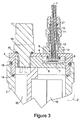
- Figures 1 to 3 show a fibre based illuminator that has a sealed light source unit and a fibre that can be releasably coupled to the light source unit without having to open or break any seal, thereby maintaining the sealing integrity of the light source unit.
- the sealed light source unit has a housing 2, which has a main body 3 and a lid 4.
- the lid 4 is threaded to the body 3 and sealed using two seals: a main seal 14 and a secondary seal 15.
- the body 3 and lid 4 may be made of any suitable material, for example, aluminium alloy.
- a primary light source 7 This is mounted on a heat-sink interface 9, see Figure 3 .
- a conical non-imaging light concentrator 8 At the output of the primary light source 7 is a conical non-imaging light concentrator 8. This directs light through an optical window 5 and provides an integrated support for the window.
- the non-imaging light concentrator may be adapted to ensure that light coupled into the fibre or fibre bundle substantially fills the fibre or fibre bundle and/or may be adapted to optimise the light power coupled into the fibre or fibre bundle.
- the light may have a substantially uniform power distribution.
- the optical window 5 is transmissive to light from the source 7 and is positioned adjacent an opening through the lid 4, so that light can pass from the interior of the sealed housing to the exterior.
- a seal 6 is provided on an upper surface of the optical window 5. This is sized to match the opening through the lid 4 and to form a seal to ensure that interior of the housing is isolated.
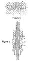
- the primary light source 7, the integrated heat-sink interface 9, the conical non-imaging light concentrator 8, and the optical window 5 together form a composite, integrated structure, as shown in Figure 4 .
- the depth of this structure may be 13mm or less.
- the composite structure is formed as a separate unit for insertion into the lid 4, thereby simplifying manufacture. Doing this means the unit can be readily adapted for different environments without needing a product re-design every time. This is because the window of the structure can be varied depending on the strength needed for a particular environment.
- the composite structure integrates the functionalities of: matching the primary light source with the characteristics of the fibre through the conical non-imaging light concentrator; retaining and locating the window; securely positioning the primary light source; providing when assembled an efficient heat-sink, and sealing the window thereby affording protection of the light source and other components from the external environment.
- a constant current driver 20 and a battery 19 are provided to power the primary light source 7.
- an electrical connector (male/female) 18 is sealed to the canister lid 4 using seal 16.
- the electrical connector 18 can be any suitable electrical wet connect. These are well known and so will not be described in detail. Power can be provided by the battery or through the electrical cable 17.
- a control system for controlling light emission could be provided within the sealed environment of the housing, for example, a control system for controlling light emission.
- means may be provided for sending and/or receiving at least one data carrying optical signal along the light rope.
- the fibre or fibre bundle assumes a dual functionality in providing both illumination and communications.
- the means for sending at least one data carrying optical signal along the fibre may modulate light from the light source 7, the modulation representing the data-carrying signal and/or by injecting data carrying light from another source (not shown) into the fibre.
- a processor may be provided inside the housing.
- a quick release positive fibre locking mechanism is provided, with one part on the lid 4 and the other on the end of the fibre.
- the lid 4 has a locator element that has a cylindrical threaded portion that is sized to match a thread in the opening through the lid 4, so it can be threaded into position.
- the locator element widens out to define a further cylindrical portion, which provides support for a mate connector part 12 of the quick release locking mechanism.
- the male connector 12 is fixed to the locator element and has a bayonet mount connection for mating with a corresponding female connector element 11, which extends round the optical fibre.
- the male and female connector elements interact to position the fibre 1 securely on the lid.
- the height of the locator element, the size of the connector parts and the position of the end of the fibre(s) are selected so that when the male and female parts are connected the ends of the fibre are in contact with the window 5 and maintain good fibre/window interface.
- the arrangement is such that the end of the fibre or fibre bundle is in direct contact with the window.
- the light source unit is provided as a fully sealed / closed unit, which, depending on the application may be waterproof and/or fireproof and/or explosion proof (Ex).
- Ex explosion proof
- a user merely has to use the simple press mechanism of the bayonet connector. There is no need to open or break the seal of the housing to make the connection. Instead, the connection is made entirely externally.
- the physical relationship between the integrated light source and window, and the connecter ensures accurate alignment of the fibre or fibre bundle with the output of the light source. Because of the sealed nature of the unit, the fibre can be connected above or below water.
- An illumination unit in accordance with the invention has been made and pressure tested to a depth of 1000 m. In these tests, the unit was made of marine grade aluminium alloy.
- the illuminator of the present invention can be used in numerous applications, For example in hazardous environments; underwater including ROV and derivatives; umbilical (all environments); distributed communications; safety; escape/guide path; marine; offshore including helipads; petrochemical; mines; tunnels; wind generation facilities both on and off shore; tidal and wave generation, and aqua-farming. Also, it can be used with end and / or side emitting fibre and or fibre bundles for the purpose of illumination, communication and dual functionality of illumination and communication.
- the illuminator of the invention can be used in an underwater umbilical system.
- Figures 6 and 7 illustrate an umbilical.
- This has various conventional umbilical parts 23 wound together, such as a gas hose and a power line, as best seen in Figure 7 .
- the umbilical includes a fibre bundle 25 that has multiple side-emitting optical fibres 27.
- the side emitting optical fibres 27 provide a distributed source of light that allows the umbilical to be lit along its length, thereby providing a guide-path as well as general illumination of the subsea environment within which the diver or divers are working.
- a light emitting diode (LED) 29 powered by a driver 31 is provided for illuminating the rope.
- the LED 29 is enclosed within a compact watertight inclosure or light-box 33 which is located adjacent an umbilical interconnect-interface 35. Radiation from the LED 29 passes through an optical coupling 36 arrangement, which transforms the spatial characteristics of the primary radiation from the LED 29 to optimize its coupling into the fibre-bundle 25. The radiation then passes through a window 37, which is mounted on a water-tight seal 39 on the side of the watertight compartment 33, before entering the fibre-bundle 25. The prepared ends of the fibres making up the bundle 25 are held in compression by element 41 so as to be in contact with and butt-coupled to the outer surface of the window 37.
- the optical arrangement described is such that this location of the fibre-end also optimizes the coupling of the radiation into the fibre.
- any LED may be used, in a preferred example, the LED generates light in the green spectral region.
- the optical output power from the LED in the green spectral region is of the order of 400 mW, and the coupling efficiency for this radiation into the fibre is of the order of 23-28%.
- the fibre bundle may be made up of any number of fibres.
- fourteen individual plastic fibres 43 are used with a core diameter of 0.74mm and refractive index of 1.49, and with an outer cladding of wall thickness 0.06mm and refractive index 1.40, see Figure 8 .
- these fibres would conform to Eska CK30 fibre.
- the fibres are wound in a tight helical bundle 45 with a pitch of 10cm, see Figure 9 .
- the packing of the fibres as appears at each end of the bundle is of the form of four central fibres surrounded by ten other fibres, all encased within an outer sheath 47 that is transparent to the light that is to be used, see Figure 10 .
- the plastic sheaf has a nominal wall thickness of 0.85mm, the walls of the sheaf being transparent to the green radiation.
- the fibre bundle is of length 100m, compatible with a standard umbilical.
- the fibre-bundle geometry of Figure 10 typically experiences a loss of the order of 5%/m due to radiation escaping through the side walls as required, this being determined both by the tightness of winding and the compression of the bundle by the outer sleeve. Both these aspects are controllable for the purposes of optimization during the manufacturing process. For the specifications given above satisfactory illumination and brightness of emission is attained for fibre lengths up to 100m.
- the watertight compartment 33 also contains a back-up battery 49 (3 hours of steady state lighting or six hours on flash) with a built in charger circuit 51. This circuit contains the flash interface which is controlled from the surface by the dive supervisor. This will also allow remote operation in the event on no mains. The system in normal operation requires 12W @18V DC.
- FIG. 11 shows a compact watertight pressurised light-box 53 designed to operate at depth of typical dimensions 100mmx50mm diameter which is attached at the diver end to the fibre and contains a rechargable battery 55, LED 57, associated driver circuit 59, optical coupling arrangement 61, and output coupling window 63 with facility for butt-coupling the fibre ends as previously.
- the light injected into the fibre bundle may be modulated so as to carry a message or information.
- the modulation of light may be such that it can be seen directly by eye, for example in the case of a general warning message.
- an optical receiver capable of decoding the modulated message may be provided for subsequent oral, visual or other mode of presentation to divers or other relevant parties.
- a controller may be provided at one or both ends of the umbilical to cause the light emitted from the fibres to be altered.
- the light could be caused to flash on and off. This could be used by divers in emergency situations to provide a general warning, for example, highlighting a change in operational conditions or a specific diver in difficulty, thereby making colleagues immediately aware of a change state.
- a lit and flashing umbilical could speed up rescue operations in identifying the diver at risk.
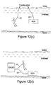
- Figure 12 shows various different operational environments in which the umbilical could be used. These include between the surface and a subsea location (surface-air diving application), Figure 12(a) or between a diving bell and individual divers (saturation diving), Figure 12(b) . It may also be used between two or more subsea locations for example in connection with remote operating vehicles (ROVs) Figure 12(c) .
- ROVs remote operating vehicles
- Figure 11 shows a simple compression element
- any suitable external fixing element could be used to releasably secure the fibre or fibre bundle in place.
- Figure 13 shows a fibre termination arrangement where the fibre bundle with individual fibres is retained within a compression ferrule 65 that holds the fibres in a given orientation and with a square end face for efficient butt coupling to the light source or optical window.
- Figure 14 shows another coupling assembly utilising a controlled compression system where the fibre is held against the output coupling window 67 and uses a tapered clamp arrangement 69 that allows uniform compression on the fibre bundle while retaining the fibre against the window 67.
- the optical coupling window 67 is provided in a tubular recess in the housing that has a screw thread 71 formed at one end.
- a tubular part 73 Mounted against the window 67 is a tubular part 73 that is shaped to receive the end section of the fibre bundle, so that light can pass through the window between the interior of the housing and the ends of the fibres.
- the external surface of the end of the tube remote from the window is tapered, to form an inwardly sloping surface 73. This is shaped to mate with a fixing element.
- the fixing element 75 has an externally formed screw thread 77 matched to the screw thread 79 on the housing and a tapered surface 81 matched to the taper 73 on the tubular part.
- the fibre bundle can be coupled to the light box by inserting it into the tubular part until the end of the fibre bundle makes contact with the window.
- compression is applied to the tubular part through engagement of the tapered surfaces 73 and 81, thereby transferring linear compression both through the fibre bundle and through the tubular part to the window. This ensures good butt coupling and hence optical interface to the window, while simultaneously applying radial compression to the fibre bundle hence retaining the fibre bundle in its position against the window.
- the coupling arrangement(s) outlined can be utilised in a variety of applications that require efficient light injection and or ability to connect/disconnect rapidly without breaking the sealing arrangement of the light-box device.
- the present invention provides a safe, low-power light-source that can be readily coupled into a side emitting fibre rope to provide a continuous, flexible and distributed along the full length of the umbilical
- the source can be used in any underwater environment for example subsea and any inland waters including lakes, rivers, lochs, harbours, docks, canals and all other types of waterways.
- the source requires no electrical power within the structure of the umbilical itself and can provide high intensity light at the peak eye response, as well as light of other colours if required. It provides a clear return path back to safety resulting from the distributed and continuous nature of the source along the length of the umbilical. It provides visual information between divers as to their relative locations in the subsea environment, as well as general illumination of the underwater working environment thereby increasing the visual acuity of operatives so improving both their safety and their efficiency of working.
- the invention is described with reference to a bundle or ribbon of fibres, a single fibre or a light pipe may be used.
- the fibre (bundle, ribbon, single or otherwise) may be provided as part of a material or a garment.
- the fibre may be integrated into a wearable item, such as an item of clothing, e.g. safety apparel.
- the wavelength of the radiation generated by the laser may be shifted in frequency by some optically non linear technique so as to be suited to the purpose. Whilst green is a preferred colour any spectral colour may be used. Accordingly the above description of the specific embodiment is made by way of example only and not for the purposes of limitation. It will be clear to the skilled person that minor modifications may be made without significant changes to the operation described.
Landscapes
- Physics & Mathematics (AREA)
- General Physics & Mathematics (AREA)
- Optics & Photonics (AREA)
- Optical Couplings Of Light Guides (AREA)
- Arrangement Of Elements, Cooling, Sealing, Or The Like Of Lighting Devices (AREA)
- Dental Tools And Instruments Or Auxiliary Dental Instruments (AREA)
Applications Claiming Priority (3)
| Application Number | Priority Date | Filing Date | Title |
|---|---|---|---|
| GB201005485A GB201005485D0 (en) | 2010-03-31 | 2010-03-31 | Fibre coupling |
| GBGB1101927.0A GB201101927D0 (en) | 2011-02-04 | 2011-02-04 | Integrated illuminator |
| EP11713503 | 2011-03-30 |
Related Parent Applications (1)
| Application Number | Title | Priority Date | Filing Date |
|---|---|---|---|
| EP11713503.8 Division | 2011-03-30 |
Publications (2)
| Publication Number | Publication Date |
|---|---|
| EP2592455A2 true EP2592455A2 (de) | 2013-05-15 |
| EP2592455A3 EP2592455A3 (de) | 2013-11-20 |
Family
ID=44070030
Family Applications (1)
| Application Number | Title | Priority Date | Filing Date |
|---|---|---|---|
| EP20120184718 Withdrawn EP2592455A3 (de) | 2010-03-31 | 2011-03-30 | Integrierte Leuchte |
Country Status (5)
| Country | Link |
|---|---|
| US (1) | US9547133B2 (de) |
| EP (1) | EP2592455A3 (de) |
| AU (1) | AU2011234253C1 (de) |
| CA (1) | CA2794327C (de) |
| WO (1) | WO2011121290A2 (de) |
Cited By (1)
| Publication number | Priority date | Publication date | Assignee | Title |
|---|---|---|---|---|
| CN108182991A (zh) * | 2018-01-20 | 2018-06-19 | 上海禹海科技有限公司 | 一种水下hdpe脐带缆穿舱密封工艺 |
Families Citing this family (8)
| Publication number | Priority date | Publication date | Assignee | Title |
|---|---|---|---|---|
| CH707209A2 (it) * | 2012-11-15 | 2014-05-15 | Alessandro Pasquali | Metodo della captazione e trasmissione dei segnali luminosi attraverso antenna ottica. |
| US20140268864A1 (en) * | 2013-03-14 | 2014-09-18 | Radast Design LLC | Modular waveguide light fixture |
| JP6236912B2 (ja) | 2013-06-24 | 2017-11-29 | 住友電気工業株式会社 | 光受信器及びその光軸調芯方法 |
| DE102016105343B4 (de) | 2016-03-22 | 2019-07-18 | Müller & Geihsler GmbH | Unterwasserfahrzeug |
| US10673539B2 (en) | 2016-08-25 | 2020-06-02 | King Abdullah University Of Science And Technology | Systems and methods for underwater illumination, survey, and wireless optical communications |
| US10556696B2 (en) * | 2016-08-26 | 2020-02-11 | Textron Innovations Inc. | Illuminated rope as an aircraft emergency egress aid |
| GB201617704D0 (en) * | 2016-10-19 | 2016-11-30 | University Court Of The University Of St Andrews The | Illuminator |
| US11110304B2 (en) * | 2017-10-20 | 2021-09-07 | Textron Innovations Inc. | Integrated emergency egress equipment |
Citations (1)
| Publication number | Priority date | Publication date | Assignee | Title |
|---|---|---|---|---|
| WO2009123017A1 (ja) * | 2008-03-31 | 2009-10-08 | 京セラ株式会社 | 光レセプタクルおよびこれを用いた光モジュール |
Family Cites Families (34)
| Publication number | Priority date | Publication date | Assignee | Title |
|---|---|---|---|---|
| US2002107A (en) * | 1934-03-29 | 1935-05-21 | Roman A Heilman | Illuminated hose nozzle |
| US2860236A (en) * | 1955-05-05 | 1958-11-11 | Will F Wilson | Light fixture |
| US3612852A (en) * | 1969-05-23 | 1971-10-12 | Armen Bogossian | Leak-proof light |
| DE2122330C3 (de) * | 1971-05-06 | 1978-11-23 | Original Hanau Quarzlampen Gmbh, 6450 Hanau | Operationsleuchte |
| GB1456395A (en) * | 1973-11-16 | 1976-11-24 | Bicc Ltd | Optical fibre connector |
| GB1523163A (en) | 1976-06-11 | 1978-08-31 | Nat Res Dev | Diving equipment |
| GB1605112A (en) * | 1977-11-08 | 1981-12-16 | Challenger Eng Ltd | Underwater lighting |
| US4307934A (en) * | 1978-05-08 | 1981-12-29 | General Dynamics, Pomona Division | Packaged fiber optic modules |
| US4814948A (en) * | 1987-07-02 | 1989-03-21 | Yasuo Hasegawa | Light-emitting-end mounting mechanism in optical display panel |
| GB2214004B (en) | 1987-12-18 | 1992-03-18 | Nl Petroleum Services | Electrical connectors incorporating automatic power control |
| US5140216A (en) * | 1988-05-27 | 1992-08-18 | Darr David W | Explosion proof lamp with liquid extinguishant |
| SE468150B (sv) * | 1991-05-06 | 1992-11-09 | Asea Brown Boveri | Optoelektronisk komponent |
| JPH0595169A (ja) * | 1991-10-02 | 1993-04-16 | Nec Corp | 半導体レーザ装置および半導体レーザモジユール |
| JPH06300943A (ja) * | 1993-04-16 | 1994-10-28 | Sumitomo Electric Ind Ltd | 半導体素子モジュール |
| US5526455A (en) * | 1993-09-17 | 1996-06-11 | Sumitomo Electric Industries, Ltd. | Connector including opposing lens surfaces, side surfaces, and contact surfaces for coupling optical devices |
| US5537503A (en) * | 1993-10-25 | 1996-07-16 | Matsushita Electric Industrial Co., Ltd. | Optical semiconductor module and method of fabricating the same |
| US5511140A (en) * | 1994-10-13 | 1996-04-23 | International Business Machines Corporation | Molded plastic optical fiber-optoelectronic converter subassembly |
| US5647656A (en) | 1995-05-12 | 1997-07-15 | Clark- Reliance Corporation | Illuminated fluid level indicator |
| AU715687B2 (en) * | 1996-01-19 | 2000-02-10 | Lumenyte International Corporation | Side lighting optical conduit |
| US5821695A (en) * | 1996-08-06 | 1998-10-13 | Appleton Electric Company | Encapsulated explosion-proof pilot light |
| US5852697A (en) * | 1997-01-03 | 1998-12-22 | Williams; Ronald R. | Combination light source and connector |
| US6144787A (en) * | 1998-05-04 | 2000-11-07 | Coherent, Inc. | Aiming and focussing device for fiber-transported laser radiation |
| US7296989B2 (en) * | 1998-05-22 | 2007-11-20 | Mtp, Inc. | Continuous production of plastic siding panels with separate shingle appearance |
| FR2786850B1 (fr) * | 1998-12-08 | 2001-01-19 | Optectron Ind | Generateurs de lumiere etanches pour fibres optiques plastiques et en verre |
| JP2000180733A (ja) * | 1998-12-15 | 2000-06-30 | Olympus Optical Co Ltd | 内視鏡装置 |
| DE10001875C2 (de) * | 2000-01-18 | 2002-01-24 | Infineon Technologies Ag | Optisches Sende-/Empfangsmodul mit internem Lichtwellenleiter |
| US6742916B1 (en) * | 2000-09-08 | 2004-06-01 | Charles B. Dunn | Fiber optic light assembly and mounting apparatus for boats |
| JP2003014992A (ja) * | 2001-07-02 | 2003-01-15 | Matsushita Electric Ind Co Ltd | 半導体レーザモジュールおよび光伝送システム |
| JP2006066875A (ja) * | 2004-07-26 | 2006-03-09 | Fuji Photo Film Co Ltd | レーザモジュール |
| US7217022B2 (en) | 2004-08-31 | 2007-05-15 | Opto Technology, Inc. | Optic fiber LED light source |
| JP2007206336A (ja) * | 2006-02-01 | 2007-08-16 | Seiko Epson Corp | 光モジュールおよびその製造方法 |
| US7296938B1 (en) * | 2006-05-25 | 2007-11-20 | Extreme Broadband Engineering, Llc | Fiber node with active optical to RF interface connector |
| US7641358B1 (en) * | 2007-06-13 | 2010-01-05 | Sunlite Safety Products, LLC | Explosion proof lantern |
| AU2009210391A1 (en) * | 2008-08-21 | 2010-03-11 | Ampcontrol Pty Ltd | Illumination system |
-
2011
- 2011-03-30 CA CA2794327A patent/CA2794327C/en not_active Expired - Fee Related
- 2011-03-30 AU AU2011234253A patent/AU2011234253C1/en not_active Ceased
- 2011-03-30 US US13/634,507 patent/US9547133B2/en not_active Expired - Fee Related
- 2011-03-30 EP EP20120184718 patent/EP2592455A3/de not_active Withdrawn
- 2011-03-30 WO PCT/GB2011/000481 patent/WO2011121290A2/en not_active Ceased
Patent Citations (1)
| Publication number | Priority date | Publication date | Assignee | Title |
|---|---|---|---|---|
| WO2009123017A1 (ja) * | 2008-03-31 | 2009-10-08 | 京セラ株式会社 | 光レセプタクルおよびこれを用いた光モジュール |
Cited By (2)
| Publication number | Priority date | Publication date | Assignee | Title |
|---|---|---|---|---|
| CN108182991A (zh) * | 2018-01-20 | 2018-06-19 | 上海禹海科技有限公司 | 一种水下hdpe脐带缆穿舱密封工艺 |
| CN108182991B (zh) * | 2018-01-20 | 2019-06-14 | 上海禹海科技有限公司 | 一种水下hdpe脐带缆穿舱密封工艺 |
Also Published As
| Publication number | Publication date |
|---|---|
| WO2011121290A3 (en) | 2012-01-05 |
| EP2592455A3 (de) | 2013-11-20 |
| AU2011234253B2 (en) | 2015-01-22 |
| CA2794327C (en) | 2018-01-23 |
| CA2794327A1 (en) | 2011-10-06 |
| AU2011234253A1 (en) | 2012-10-11 |
| US20130064556A1 (en) | 2013-03-14 |
| US9547133B2 (en) | 2017-01-17 |
| WO2011121290A2 (en) | 2011-10-06 |
| AU2011234253C1 (en) | 2015-08-27 |
| US20130272720A9 (en) | 2013-10-17 |
Similar Documents
| Publication | Publication Date | Title |
|---|---|---|
| AU2011234253B2 (en) | Integrated illuminator | |
| US8475083B2 (en) | Umbilical for underwater diving | |
| US4544233A (en) | Underwater optical fiber connector | |
| JP6058670B2 (ja) | 電気−光イーサネット伝送システム用の海底電気−光コネクタ・ユニット | |
| CN109154702A (zh) | 可追踪端点电缆组件 | |
| EP0058884A1 (de) | Vorrichtung zum Streuen von Licht aus einem Lichtleitkabel | |
| CN104538788B (zh) | 一种光纤水听器阵列光电复合缆快速接驳装置 | |
| EP3104480B1 (de) | Unterseeisches datenübertragungskabel | |
| US20240402233A1 (en) | Cable monitoring apparatus and method | |
| CN110212485A (zh) | 一种三芯高压海底电缆接头盒及其安装方法 | |
| CN112368895A (zh) | 包括电缆压盖、电线传输元件和外壳的成套部件、由该成套部件制成的系统以及功能性连接该系统的方法 | |
| CN108645445B (zh) | 一种用于海底管柱的光纤分布式监测系统 | |
| CA2698292C (en) | Umbilical | |
| AU2010201284B2 (en) | Umbilical | |
| US5305407A (en) | Apparatus and method for underwater fiber-optic coupling | |
| WO2018073575A1 (en) | Assembly for a side emitting optical fibre | |
| CN210487230U (zh) | 一种便携式光缆测试仪 | |
| RU2433431C2 (ru) | Соединительная муфта для подводного волоконно-оптического кабеля | |
| CN109164540A (zh) | 一种光纤连接接头及采用该接头的尾纤 | |
| CN223428140U (zh) | 一种新型深海光电接头盒 | |
| Jenkins et al. | Utilizing pressure balanced oil filled (PBOF) hose cable assemblies with electric and fiber optic connectors | |
| JP2022102791A (ja) | 深海用自然変状検知装置 | |
| RU2400002C1 (ru) | Кабельная оптическая линия подводного средства | |
| CN115274189A (zh) | 深潜设备用线缆、线缆组件以及充油方法 | |
| Wieboldt | Implementation of a fiber optic telemetry link aboard a deep submergence ROV system. |
Legal Events
| Date | Code | Title | Description |
|---|---|---|---|
| PUAI | Public reference made under article 153(3) epc to a published international application that has entered the european phase |
Free format text: ORIGINAL CODE: 0009012 |
|
| AK | Designated contracting states |
Kind code of ref document: A2 Designated state(s): AL AT BE BG CH CY CZ DE DK EE ES FI FR GB GR HR HU IE IS IT LI LT LU LV MC MK MT NL NO PL PT RO RS SE SI SK SM TR |
|
| AX | Request for extension of the european patent |
Extension state: BA ME |
|
| PUAL | Search report despatched |
Free format text: ORIGINAL CODE: 0009013 |
|
| AK | Designated contracting states |
Kind code of ref document: A3 Designated state(s): AL AT BE BG CH CY CZ DE DK EE ES FI FR GB GR HR HU IE IS IT LI LT LU LV MC MK MT NL NO PL PT RO RS SE SI SK SM TR |
|
| AX | Request for extension of the european patent |
Extension state: BA ME |
|
| RIC1 | Information provided on ipc code assigned before grant |
Ipc: G02B 6/00 20060101ALI20131014BHEP Ipc: G02B 6/04 20060101ALN20131014BHEP Ipc: G02B 6/40 20060101ALN20131014BHEP Ipc: F21V 8/00 20060101ALI20131014BHEP Ipc: H04B 10/00 20130101ALI20131014BHEP Ipc: G02B 6/42 20060101AFI20131014BHEP Ipc: G02B 6/38 20060101ALN20131014BHEP Ipc: F21V 31/00 20060101ALI20131014BHEP |
|
| 17P | Request for examination filed |
Effective date: 20140519 |
|
| RBV | Designated contracting states (corrected) |
Designated state(s): AL AT BE BG CH CY CZ DE DK EE ES FI FR GB GR HR HU IE IS IT LI LT LU LV MC MK MT NL NO PL PT RO RS SE SI SK SM TR |
|
| STAA | Information on the status of an ep patent application or granted ep patent |
Free format text: STATUS: EXAMINATION IS IN PROGRESS |
|
| 17Q | First examination report despatched |
Effective date: 20170321 |
|
| GRAP | Despatch of communication of intention to grant a patent |
Free format text: ORIGINAL CODE: EPIDOSNIGR1 |
|
| STAA | Information on the status of an ep patent application or granted ep patent |
Free format text: STATUS: GRANT OF PATENT IS INTENDED |
|
| RIC1 | Information provided on ipc code assigned before grant |
Ipc: F21V 31/00 20060101ALI20201124BHEP Ipc: H04B 10/00 20130101ALI20201124BHEP Ipc: G02B 6/04 20060101ALN20201124BHEP Ipc: F21V 8/00 20060101ALI20201124BHEP Ipc: G02B 6/00 20060101ALI20201124BHEP Ipc: G02B 6/38 20060101ALN20201124BHEP Ipc: G02B 6/42 20060101AFI20201124BHEP Ipc: G02B 6/40 20060101ALN20201124BHEP |
|
| INTG | Intention to grant announced |
Effective date: 20201217 |
|
| STAA | Information on the status of an ep patent application or granted ep patent |
Free format text: STATUS: THE APPLICATION IS DEEMED TO BE WITHDRAWN |
|
| 18D | Application deemed to be withdrawn |
Effective date: 20210429 |