EP2592333B1 - Lichtleitelement für einen Kraftfahrzeugscheinwerfer - Google Patents
Lichtleitelement für einen Kraftfahrzeugscheinwerfer Download PDFInfo
- Publication number
- EP2592333B1 EP2592333B1 EP12191547.4A EP12191547A EP2592333B1 EP 2592333 B1 EP2592333 B1 EP 2592333B1 EP 12191547 A EP12191547 A EP 12191547A EP 2592333 B1 EP2592333 B1 EP 2592333B1
- Authority
- EP
- European Patent Office
- Prior art keywords
- light
- light guide
- region
- guide element
- area
- Prior art date
- Legal status (The legal status is an assumption and is not a legal conclusion. Google has not performed a legal analysis and makes no representation as to the accuracy of the status listed.)
- Active
Links
Images
Classifications
-
- F—MECHANICAL ENGINEERING; LIGHTING; HEATING; WEAPONS; BLASTING
- F21—LIGHTING
- F21S—NON-PORTABLE LIGHTING DEVICES; SYSTEMS THEREOF; VEHICLE LIGHTING DEVICES SPECIALLY ADAPTED FOR VEHICLE EXTERIORS
- F21S41/00—Illuminating devices specially adapted for vehicle exteriors, e.g. headlamps
- F21S41/10—Illuminating devices specially adapted for vehicle exteriors, e.g. headlamps characterised by the light source
- F21S41/14—Illuminating devices specially adapted for vehicle exteriors, e.g. headlamps characterised by the light source characterised by the type of light source
- F21S41/141—Light emitting diodes [LED]
-
- B—PERFORMING OPERATIONS; TRANSPORTING
- B60—VEHICLES IN GENERAL
- B60Q—ARRANGEMENT OF SIGNALLING OR LIGHTING DEVICES, THE MOUNTING OR SUPPORTING THEREOF OR CIRCUITS THEREFOR, FOR VEHICLES IN GENERAL
- B60Q1/00—Arrangement of optical signalling or lighting devices, the mounting or supporting thereof or circuits therefor
- B60Q1/02—Arrangement of optical signalling or lighting devices, the mounting or supporting thereof or circuits therefor the devices being primarily intended to illuminate the way ahead or to illuminate other areas of way or environments
- B60Q1/04—Arrangement of optical signalling or lighting devices, the mounting or supporting thereof or circuits therefor the devices being primarily intended to illuminate the way ahead or to illuminate other areas of way or environments the devices being headlights
-
- F—MECHANICAL ENGINEERING; LIGHTING; HEATING; WEAPONS; BLASTING
- F21—LIGHTING
- F21S—NON-PORTABLE LIGHTING DEVICES; SYSTEMS THEREOF; VEHICLE LIGHTING DEVICES SPECIALLY ADAPTED FOR VEHICLE EXTERIORS
- F21S41/00—Illuminating devices specially adapted for vehicle exteriors, e.g. headlamps
- F21S41/20—Illuminating devices specially adapted for vehicle exteriors, e.g. headlamps characterised by refractors, transparent cover plates, light guides or filters
- F21S41/24—Light guides
-
- F—MECHANICAL ENGINEERING; LIGHTING; HEATING; WEAPONS; BLASTING
- F21—LIGHTING
- F21S—NON-PORTABLE LIGHTING DEVICES; SYSTEMS THEREOF; VEHICLE LIGHTING DEVICES SPECIALLY ADAPTED FOR VEHICLE EXTERIORS
- F21S43/00—Signalling devices specially adapted for vehicle exteriors, e.g. brake lamps, direction indicator lights or reversing lights
- F21S43/10—Signalling devices specially adapted for vehicle exteriors, e.g. brake lamps, direction indicator lights or reversing lights characterised by the light source
- F21S43/13—Signalling devices specially adapted for vehicle exteriors, e.g. brake lamps, direction indicator lights or reversing lights characterised by the light source characterised by the type of light source
- F21S43/14—Light emitting diodes [LED]
-
- F—MECHANICAL ENGINEERING; LIGHTING; HEATING; WEAPONS; BLASTING
- F21—LIGHTING
- F21S—NON-PORTABLE LIGHTING DEVICES; SYSTEMS THEREOF; VEHICLE LIGHTING DEVICES SPECIALLY ADAPTED FOR VEHICLE EXTERIORS
- F21S43/00—Signalling devices specially adapted for vehicle exteriors, e.g. brake lamps, direction indicator lights or reversing lights
- F21S43/20—Signalling devices specially adapted for vehicle exteriors, e.g. brake lamps, direction indicator lights or reversing lights characterised by refractors, transparent cover plates, light guides or filters
- F21S43/235—Light guides
- F21S43/236—Light guides characterised by the shape of the light guide
- F21S43/241—Light guides characterised by the shape of the light guide of complex shape
-
- F—MECHANICAL ENGINEERING; LIGHTING; HEATING; WEAPONS; BLASTING
- F21—LIGHTING
- F21S—NON-PORTABLE LIGHTING DEVICES; SYSTEMS THEREOF; VEHICLE LIGHTING DEVICES SPECIALLY ADAPTED FOR VEHICLE EXTERIORS
- F21S43/00—Signalling devices specially adapted for vehicle exteriors, e.g. brake lamps, direction indicator lights or reversing lights
- F21S43/20—Signalling devices specially adapted for vehicle exteriors, e.g. brake lamps, direction indicator lights or reversing lights characterised by refractors, transparent cover plates, light guides or filters
- F21S43/235—Light guides
- F21S43/242—Light guides characterised by the emission area
- F21S43/243—Light guides characterised by the emission area emitting light from one or more of its extremities
-
- F—MECHANICAL ENGINEERING; LIGHTING; HEATING; WEAPONS; BLASTING
- F21—LIGHTING
- F21S—NON-PORTABLE LIGHTING DEVICES; SYSTEMS THEREOF; VEHICLE LIGHTING DEVICES SPECIALLY ADAPTED FOR VEHICLE EXTERIORS
- F21S43/00—Signalling devices specially adapted for vehicle exteriors, e.g. brake lamps, direction indicator lights or reversing lights
- F21S43/20—Signalling devices specially adapted for vehicle exteriors, e.g. brake lamps, direction indicator lights or reversing lights characterised by refractors, transparent cover plates, light guides or filters
- F21S43/235—Light guides
- F21S43/247—Light guides with a single light source being coupled into the light guide
-
- G—PHYSICS
- G02—OPTICS
- G02B—OPTICAL ELEMENTS, SYSTEMS OR APPARATUS
- G02B6/00—Light guides; Structural details of arrangements comprising light guides and other optical elements, e.g. couplings
- G02B6/0001—Light guides; Structural details of arrangements comprising light guides and other optical elements, e.g. couplings specially adapted for lighting devices or systems
-
- B—PERFORMING OPERATIONS; TRANSPORTING
- B60—VEHICLES IN GENERAL
- B60Q—ARRANGEMENT OF SIGNALLING OR LIGHTING DEVICES, THE MOUNTING OR SUPPORTING THEREOF OR CIRCUITS THEREFOR, FOR VEHICLES IN GENERAL
- B60Q2400/00—Special features or arrangements of exterior signal lamps for vehicles
- B60Q2400/20—Multi-color single source or LED matrix, e.g. yellow blinker and red brake lamp generated by single lamp
Definitions
- the invention relates to a light-guiding element for a light unit or a motor vehicle headlight, the light element having at least one light-coupling area for coupling light with at least one light source and the light-guiding element furthermore having at least one light-coupling area for coupling out the light.
- the invention also relates to a light unit or a motor vehicle headlight with at least one light source with such a light guide element.
- LED Light-emitting diodes
- halogen halogen
- the light emerging there then creates a light function e.g. Position light, daytime running light (DRL) or flashing light.
- DRL daytime running light
- the AT 009 091 U1 shows a light-guiding element according to the preamble of claim 1, with a light coupling-in area and a light-coupling-out area, light-guiding rods being provided between the areas, which spread out in a fan shape and have different cross sections.
- the light guide rods are designed as recesses in the light guide element.
- the EP 1895228 A1 shows a device with three zones, the first zone is used for coupling light, the second zone distributes the light evenly and in the third zone the light emerges again. Corresponding optical elements in the second zone ensure a uniform luminance.
- the WO 2011/021135 A1 shows a lens arrangement for a light source that opens up in a pot shape and consists of strip-shaped light-guiding elements.
- the light from a light source - for example an LED - is distributed via the light guide elements in the direction of a plate-shaped light exit surface.
- DE 698 33 421 T2 describes a light emission optics for vehicle signal lights, which comprises a plate made of translucent material, in which openings with concave and convex surfaces are made, which act as cylindrical lenses and allow a uniform light distribution over the translucent plate.
- a disadvantage of these known solutions is, in particular, that the light emerging via the light decoupling area is mostly inhomogeneously distributed for design reasons, which is particularly the case when using light sources with a particularly pronounced main emission direction, such as e.g. LEDs, the case and is undesirable. As a result, the light emerging via the light decoupling area appears unevenly bright or the light source is increasingly imaged.
- the known light-guiding elements are often difficult to manufacture using inexpensive injection molding processes, since the small-sized cutouts and clearances in the mold release area can cause burrs which lead to considerable light losses. Accordingly, the tools are comparatively expensive to manufacture and operate (maintenance costs).
- the light guide element according to the invention allows a uniform luminance regardless of the light source used, since the feed into the connecting element does not take place directly but via the light guide parts.
- the amount of light emerging in the light coupling area can be optimally adapted by appropriately designing the connecting element, wherein the emission characteristic of the respective light source can be taken into account.
- the optical structuring elements redirect the incident light into the light guide rods or grooves in the connecting element and thus support a homogeneous light distribution.
- the light decoupling area is favorably designed in an elegant manner with a smooth surface, which is made possible by the fact that, thanks to the solution according to the invention, the light is homogenized already in the light-guiding element.
- the surface of the light decoupling area can be designed as desired, for example structured.
- the light-guiding element according to the invention enables the legal regulations applicable to motor vehicle parts, such as ECE, SAE and CCC, to be fulfilled and has a particularly homogeneous light distribution.
- Homogeneous is understood here to mean a light distribution that has no sudden changes in intensity. However, it is not necessary that the emitted light have the same intensity everywhere; for example, the light distribution can have a maximum in the center and a decreasing intensity running towards the outer regions.
- At least one bifurcation element is provided in the beam region at the point from which the light guide parts originate.
- the crotch element is advantageously optically thinner than the rest of the light-guiding element.
- the bifurcation element can be designed, for example, as a highly thinned point of the light-guiding element or from air, that is to say as an opening or a broken-through point.
- the bifurcation element serves to ensure that the coupled light is diverted as completely as possible into the light guide parts.
- the bifurcation element helps to prevent the light source from being depicted as a direct spot in the emerging light distribution.
- the cross sections of the sub-strands are designed with different diameters.
- the diameters can increase or decrease in one direction.
- the intensity distribution of the outcoupled light can also be designed.
- the sub-strands can be designed, for example, as light guide rods and / or as light guide grooves.
- the coupled light can be guided into the light decoupling area via the sub-strands.
- the alignment of the light guide rods or light guide grooves results in the main emission direction of the entire light guide element.
- the light guide rods can be manufactured separately, structured by exemptions or carried out during injection molding.
- the grooves can be embossed or cut out after production or can be carried out directly during injection molding. Accordingly, the sub-strands can also be connected to one another, which is immediately evident when embodied as light guide grooves. But also in the case of the design as light guide rods, thin connections can exist between light guide rods arranged next to one another.
- the light guide rods and / or light guide grooves originate on the light guide parts outside the beam section and are designed such that they run in the direction of the light decoupling area in the shadow area of the beam section.
- the shadow area can be found behind the bifurcation element (if present).
- the light guide rods or light guide grooves therefore also extend into the area of the connecting element shaded by the beam partial area and ensure a homogeneous light distribution at the light decoupling area of the light guide element. This prevents the light source from being depicted as a bright intensity spot, which is often a problem, particularly when using light-emitting diodes.
- the structuring elements advantageously have a prism structure.
- the prism structure is designed in a known manner and directs the rays coming from the beam splitting area into the connecting element or into the sub-strands executed there (light guide rods or grooves). From there the light then reaches the light decoupling area and is emitted.
- Adaptable parameters of the prism structure are, for example, density and / or number and / or depth and / or width of the prisms.
- the light distribution can be further influenced if the light guide parts have different cross-sectional diameters. Depending on the situation, the light distribution can then be controlled, for example by providing the first light guide part with a larger cross-sectional diameter than the second, or vice versa.
- At least one feed element is provided between the light coupling-in area and the beam sub-area.
- the feed element is advantageously designed as a light guide. This makes it possible to position the light source and light-guiding element completely independently of one another, since the light from the light source passes through the feed element into the beam section.
- the light guiding element can thus be used in a wide variety of ways.
- the light coupling area, the beam area and the light guide parts are made in one piece.
- the connecting element and the light decoupling area can be made in one piece.
- the light coupling area, the beam part area, the light guide parts, the connecting element and the light coupling area are made in one piece.
- latching and / or referencing elements for mounting the light guide element are provided on the light guide element in the area of the light coupling area. If, for example, the light guide element is to be connected to a light source module via which the light is coupled in, these latching and / or referencing elements can ensure a fixed and at the same time releasable fixation, which at the same time permits optimal positioning of the light guide element with respect to the light sources. Correspondingly, corresponding fixing elements must then be provided in a known manner on the light source module (or the object to which the light guide element is to be connected).
- the latching and / or referencing elements also serve as centering and even referencing elements, thus ensuring that the light-guiding element can be reproducibly mounted in such a way that the desired light function is ensured or that the required light distribution is emitted.
- the amount of light that is coupled out can be increased, or the light-emitting surface and / or the illuminated area can be enlarged, in accordance with a variant of the invention, in the light coupling-out area.
- at least one shell element that is open in the beam direction is advantageously provided in the light coupling-out area, on the side of which facing away from the light coupling-in area the additional light coupling-out area is arranged.
- a first shell element with a first additional light coupling-out area and a second shell element with a second additional light coupling-out area are advantageously provided.
- the object mentioned at the outset is also achieved according to the invention by a light unit or a motor vehicle headlight mentioned at the outset, at least one light guide element being provided for coupling in light from at least one light source.
- the motor vehicle headlight is used, for example, to generate a light function such as position light, daytime running light (DRL - Daytime Running Light) or flashing light.
- the light source module is set up to couple multicolored light into the light guide element. This can be achieved either by providing multiple light sources or by a single light source that can emit light in multiple colors. Depending on the desired light function, e.g. either white and / or yellow light can be coupled in.
- the light source module (or its light sources) is advantageously designed to be dimmable. This means that the light sources arranged in it are dimmable and their intensity can be changed. This enables different light intensities to be achieved, e.g. be required in the various legal provisions.
- At least one LED chip is provided as the light source in the light source module.
- Such light sources are known; of course, any other light sources known to the person skilled in the art can also be used.
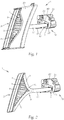
- Fig. 1 shows a light guide element 1 according to the invention in a view obliquely from the front.
- the light guide element 1 is made, for example, of light-conducting plastic, glass or other light-conducting materials, for example using the injection molding process.
- Light from at least one light source for example a light-emitting diode (LED) is fed in via a light coupling-in area 2 and exits again via a light coupling-out area 3.
- the light sources, in the present example LED chips 23, are arranged in a light source module 20 on a circuit board 22 with appropriate contact. For example, corresponding plug connections for fixing the LED chips 23 can be provided in the board 22.
- the light source module 20 further comprises a heat sink 21 for dissipating the heat generated by the operation of the LED chips 23.
- At least one light source is necessary, but it can be advantageous to provide a plurality of differently colored light sources (or a light source which can provide several colors) in order to be able to cover a broader spectrum of light functions. For example, white light is required for position light and / or DRL (daytime running light), yellow light is required for flashing light.
- DRL daytime running light
- yellow light is required for flashing light.
- the light sources are advantageously dimmable so that the different light intensities are achieved in accordance with the legal regulations mentioned above.
- the light guide element according to the invention can be used together with such a light source module 20 in a light unit or a motor vehicle headlight.
- a large part of the light-guiding element 1 is surrounded by a decorative panel 30. It serves to minimize the emission of interfering radiation caused by micro-surface defects or the like on the light-guiding element and thus to ensure a homogeneous light distribution. This also prevents light from escaping at undesired points or being reflected in the headlight system.
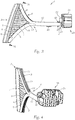
- the elements of the light-guiding element 1 described below are shown in FIGS 2 to 4 recognizable.
- a beam section 4 is arranged between the light coupling-in 2 and the light coupling-out area 3, on which the part of the light-part element 1 coming from the light-coupling-in area 2 is divided into a first 5 and a second light guide part 6, which run in directions leading away from each other.
- a bifurcation element 13 (see Fig. 3 ) be provided at the point from which the light guide parts 5, 6 extend.
- the bifurcation element 13 is made optically thinner than the rest of the light-guiding element 1, that is to say, for example, from air, that is to say as an opening or openwork point.
- a further variant would be to design the light-guiding element 1 as a highly thinned point, where the combination of a thin element layer and air as the remaining part of the fork element 13 approximates an optically thinner area. It would also be possible to use an optically thinner material that is different from the rest of the light-guiding element 1.
- a supply element 12 in the form of a light guide is provided between the light coupling-in area 2 and the beam section 4.
- the feed element 12 is short and straight in the exemplary embodiment shown, but can also be made longer or winding and arranged.
- Latching and / or referencing elements are provided on the light guide element 1, preferably on the feed element 12 (or generally speaking near the light coupling area 2), with which the light guide element 1 can be installed at its intended location.
- the latching and / or referencing elements are designed, for example, as latching lugs which interact with corresponding corresponding elements at the place of use (for example the light source module 20) of the light guide element 1. This connection can be releasable in accordance with the current design of snap-in connections.
- the latching and / or referencing elements 40 simultaneously serve for referencing, that is to say for the reproducible assembly of the light-guiding element 1.
- the latching and referencing elements 40 are basically the same, but can be used for fixation on the one hand by interacting with a corresponding counterpart on the light unit, and on the other hand without corresponding counteraction for referencing, i.e. to ensure (reproducibly) the desired light distribution.
- the light guide parts 5, 6 run in directions leading away from each other - essentially they can span an angle of up to 180 °.
- the light guide parts 5, 6 do not run in straight lines, but in curves - the angle between the light guide parts 5, 6 is thus either to be understood as the angle that straight connections between the beam section area 4 and the end point of the respective light guide part 5, 6 include, or as an angle between the tangents to the light guide parts 5, 6 at certain points.
- the course of the light guide parts 5, 6 can be selected according to the available space and the size of the span. It should be noted that the curvature of the light guide parts 5, 6 still allows total reflection of the coupled light, or that there is no excessive loss of light. In principle, the person skilled in the art can take instructions from the information given above for the implementation of the light guide parts 5, 6.
- a light-guiding connecting element 7 Arranged in the area spanned by the light guide parts 5, 6 is a light-guiding connecting element 7 which merges into the light decoupling area 3 on its side facing away from the light guide parts 5, 6.
- the light-conducting connecting element 7 has, for example, a fan-shaped feed with sub-strands which originate in the light-guide parts 5, 6 and open into the light decoupling area 3.
- the lower strands are designed as light guide rods 9.
- Fig. 5 shows a section through the light guide element 1 in Fig. 3 along the line AA - between the light guide parts 5, 6, the connecting element 7 with the light guide rods 9 can be seen.
- the cross sections of the light guide parts 5, 6 and also of the individual light guide rods 9 with one another have essentially the same diameter in the exemplary embodiment shown. Different diameters can also be selected here to influence the light distribution.
- the diameters of the light guide rods 9 can differ, for example increase or decrease, via the connecting element 7.
- the more centrally located light guide rods 9 can be made thicker or wider.
- individual light guide rods 9 can be designed with increasing and / or decreasing diameters over their length or have other changes in cross-section over their course.
- a The light guide rod 9 has a narrow diameter at the place of its origin on the light guide part 5, 6, which then increases in size in the direction of the light decoupling region 3.
- the light distribution can also be changed by varying the cross-sectional diameters of the light guide parts 5, 6, e.g. in that the diameter of the first light guide part 5 is chosen larger than the diameter of the second light guide part 6.
- the connecting element 7 can also be designed differently light-guiding due to a different design of the sub-strands, for example by providing light guiding grooves, combinations of grooves and rods and similar solutions known to the person skilled in the art.
- the sub-strands can also have connections to one another, which is evident, for example, when embodied as light guide grooves. But also in the case of the design as light guide rods, connections can exist between adjacent rods, which can be caused, for example, by production.
- the cross sections of the sub-strands can be circular, in principle also polygonal or angular or in another suitable manner. In the case of an angular design, light may be lost at the corners and edges, which is why the round or oval shape is preferable.
- the orientation of the sub-strands or the light guide rods 9 defines the main emission direction of the entire light guide element 1 and can therefore be designed to suit the area of use.
- the light guide rods 9 are designed in such a way that they also run in the shadow area 10 of the beam part area 4 in the direction of the light coupling area 3: In the beam part area 4, the part of the light guide element 1 coming from the light coupling area 2 is completely divided into the light guide parts 5, 6 - in the main beam direction this creates behind the beam section 4 a shaded part.
- this has the advantage that an increased light intensity is prevented in the area where the light source is coupled into the light guide element 1 - when using a light-emitting diode, a massively increased circular light intensity can occur, which disturbs the homogeneous luminance of the light guide element 1.
- the shadowed part causes a disturbance in the luminance, which is eliminated by the above-described design of the sub-strands (light guide rods 9).
- the light guide rods 9 are designed such that they originate outside the beam area 4 and extend in the direction of the light coupling area 3 into the shadow area of the beam area 4.
- the light guide rods 9 therefore open uniformly into the light decoupling area 3, as a result of which a homogeneous luminance of the light guide element 1 is achieved.
- the light fed in at the light coupling-in area 2 passes via the feed element 12 (if present) to the beam part area 4, where the light is guided into the light guide parts 5, 6.
- optical structuring elements 8 see Fig. 3
- the light is then introduced into the connecting element 7 or the light guide rods 9 and exits from there via the light decoupling area 3.
- the optical structuring elements 8 are arranged on the side of the light guide parts 5, 6 facing away from the light coupling-out area 3.
- the structuring elements 8 are designed as a prism structure 11 - that is to say as a series of prisms; other designs with which the light can be guided accordingly into the connecting element 7 are also possible. By cleverly designing this prism structure 11, the light can already be pre-homogenized.
- Adaptable parameters of the prism structure 11 are, for example, the number and / or depth and / or width of the prisms.
- the light decoupling area 3 is constructed with a smooth surface, which is often advantageous for design reasons.
- the light decoupling area 3 can, however, also be designed differently, for example in order to achieve a higher luminous efficiency, to enlarge the illuminated surface or the light-emitting surface.
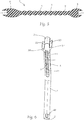
- Fig. 6 shows such a variant in which a light guide element 1 according to the invention can be seen from the side (this view corresponds to the view from above when installed).
- two additional light coupling-out areas 51, 53 are provided, which are designed as shell elements 50, 52 which are open in the beam direction and on whose side facing away from the light coupling-in area 2 the additional light coupling-out areas are arranged.
- the first shell element 50 with the first additional light output region 51 and the second shell element 52 with the second additional light output region 53 are arranged on opposite sides of the light guide element 1.
- the provision of the additional light coupling-out areas 51, 53 increases the illuminated area, which is advantageous for reasons of better visibility (e.g. with daytime running lights). With certain light distributions, the illuminated area is legally determined and must not be less than a limit.
- the additional light coupling-out areas 51, 53 can be designed with a smooth surface but can also have an additional structuring in order to enlarge the light-emitting surface or to influence the amount of light emitted via these areas.
- the entire light-guiding element 1 is made in one piece, light coupling-in area 2, beam section 4, light-guiding parts 5, 6, connecting element 7 and light coupling-out area 3 thus form a unit.
- only light coupling-in area 2, beam part area 4 and the Light guide parts 5, 6 are made in one piece, or only connecting element 7 and light guide parts 5, 6.
Landscapes
- Engineering & Computer Science (AREA)
- General Engineering & Computer Science (AREA)
- Physics & Mathematics (AREA)
- Optics & Photonics (AREA)
- Microelectronics & Electronic Packaging (AREA)
- General Physics & Mathematics (AREA)
- Mechanical Engineering (AREA)
- Non-Portable Lighting Devices Or Systems Thereof (AREA)
- Lighting Device Outwards From Vehicle And Optical Signal (AREA)
- Optical Couplings Of Light Guides (AREA)
- Light Guides In General And Applications Therefor (AREA)
Description
- Die Erfindung betrifft ein Lichtleitelement für eine Lichteinheit bzw. einen Kraftfahrzeugscheinwerfer, wobei das Lichtelement zumindest einen Lichteinkoppelbereich zum Einkoppeln von Licht mit zumindest einer Lichtquelle aufweist und das Lichtleitelement weiters zumindest einen Lichtauskoppelbereich zum Auskoppeln des Lichts aufweist. Die Erfindung betrifft außerdem eine Lichteinheit bzw. einen Kraftfahrzeugscheinwerfer mit zumindest einer Lichtquelle mit einem derartigen Lichtleitelement.
- Es sind verschiedene Arten von Lichtleitelementen zum Bündeln von Licht bekannt. Das Licht von einer oder mehreren Lichtquellen, z.B. Leuchtdioden (LED), Halogen-, Xenon- oder Entladungslampen wird im Lichteinkoppelbereich in das Lichtleitelement eingekoppelt und gelangt dann auf verschiedene Arten zum Lichtauskoppelbereich. Das dort austretende Licht erzeugt dann eine Lichtfunktion, z.B. Positionslicht, Tagfahrlicht (DRL - daytime running light) oder Blinklicht.
- Die
AT 009 091 U1 - Die
EP 1895228 A1 zeigt eine Vorrichtung mit drei Zonen, wobei die erste Zone zur Einkopplung von Licht dient, die zweite Zone das Licht gleichmäßig verteilt und in der dritten Zone das Licht wieder austritt. Entsprechende optische Elemente in der zweiten Zone sorgen dabei für eine gleichmäßige Leuchtdichte. - Die
WO 2011/021135 A1 zeigt eine Linsenanordnung für eine Leuchtquelle, die topfförmig aufgeht und aus streifenförmigen lichtleitenden Elementen besteht. Das Licht einer Lichtquelle - z.B. einer LED - wird über die Lichtleiterelemente in Richtung einer plattenförmigen Lichtaustrittsfläche verteilt. -
DE 698 33 421 T2 beschreibt eine Lichtabgabeoptik für Fahrzeugsignalleuchten, die eine Platte aus lichtdurchlässigem Material umfasst, in der Öffnungen mit konkaven und konvexen Flächen ausgeführt sind, die als Zylinderlinsen fungieren und eine gleichmäßige Lichtverteilung über die lichtdurchlässige Platte ermöglichen. - Nachteilig an diesen bekannten Lösungen ist insbesondere, dass das über den Lichtauskoppelbereich austretende Licht meist aus konstruktiven Gründen inhomogen verteilt ist, was insbesondere bei Verwendung von Lichtquellen mit besonders stark ausgeprägter Hauptabstrahlrichtung, wie z.B. LEDs, der Fall und unerwünscht ist. Dadurch wirkt das über den Lichtauskoppelbereich austretende Licht ungleichmäßig hell bzw. bildet sich die Lichtquelle verstärkt ab.
- Häufig lassen sich die bekannten Lichtleitelemente nur schwer mir günstigen Spritzgussverfahren herstellen, da die klein dimensionierten Aussparungen und Freistellungen im Formtrennbereich Grate verursachen können, die zu erheblichen Lichtverlusten führen. Dementsprechend sind dann die Werkzeuge in Herstellung und Betrieb (Wartungskosten) vergleichsweise teuer.
- Es ist daher eine Aufgabe der Erfindung, ein Lichtleitelement bereit zu stellen, das unabhängig von der verwendeten Lichtquelle eine gleichmäßige Lichtverteilung erzeugt.
- Diese Aufgabe wird erfindungsgemäß durch ein Lichtleitelement mit den Merkmalen des Anspruchs 1 gelöst.
- Das erfindungsgemäße Lichtleitelement erlaubt eine gleichmäßige Leuchtdichte unabhängig von der verwendeten Lichtquelle, da die Einspeisung in das Verbindungselement nicht direkt, sondern über die Lichtleiterteile erfolgt. Außerdem kann die im Lichtkoppelbereich austretende Lichtmenge durch entsprechende Gestaltung des Verbindungselements optimal angepasst werden, wobei die Abstrahlcharakteristik der jeweiligen Lichtquelle berücksichtigt werden kann. Die optischen Strukturierungselemente leiten das eingestrahlte Licht in die Lichtleitstäbe oder -rillen im Verbindungselement um und unterstützen damit eine homogene Lichtverteilung. Der Lichtauskoppelbereich ist günstigerweise formschön mit glatter Oberfläche konstruiert, was dadurch ermöglicht wird, dass dank der erfindungsgemäßen Lösung eine Homogenisierung des Lichts bereits im Lichtleitelement erfolgt. Natürlich kann aber die Oberfläche des Lichtauskoppelbereichs beliebig, beispielsweise strukturiert, ausgeführt werden.
- Das erfindungsgemäße Lichtleitelement erlaubt die Erfüllung der für Kraftfahrzeugteile geltenden gesetzlichen Regelungen wie beispielsweise ECE, SAE und CCC und weist eine besonders homogene Lichtverteilung auf. Unter homogen wird hier eine Lichtverteilung verstanden, die keine Intensitätssprünge aufweist. Allerdings ist es nicht notwendig, dass das emittierte Licht überall dieselbe Intensität hat; beispielsweise kann die Lichtverteilung mittig ein Maximum und zu den äußeren Bereichen hin verlaufend eine abnehmende Intensität aufweisen.
- In einer Variante der Erfindung ist im Strahlteilbereich an der Stelle, von der die Lichtleiterteile ausgehen, zumindest ein Gabelungselement vorgesehen. Das Gabelungselement ist dabei günstigerweise optisch dünner als der Rest des Lichtleitelements. Das Gabelungselement kann beispielsweise als stark verdünnte Stelle des Lichtleitelements oder aus Luft, also als Öffnung bzw. durchbrochene Stelle ausgeführt sein. Das Gabelungselement dient dazu, die möglichst vollständige Umleitung des eingekoppelten Lichts in die Lichtleiterteile sicherzustellen. Außerdem trägt das Gabelungselement dazu bei zu verhindern, dass sich die Lichtquelle als direkter Spot in der austretenden Lichtverteilung abbildet.
- In einer Variante der Erfindung sind die Querschnitte der Unterstränge mit verschiedenen Durchmessern ausgeführt. Beispielsweise können die Durchmesser in eine Richtung zu- oder abnehmen. Dadurch kann die Intensitätsverteilung des ausgekoppelten Lichts zusätzlich gestaltet werden. Die Unterstränge können beispielsweise als Lichtleitstäbe und/oder als Lichtleitrillen ausgeführt sein. Über die Unterstränge kann das eingekoppelte Licht in den Lichtauskoppelbereich geführt werden. Die Ausrichtung der Lichtleitstäbe bzw. Lichtleitrillen ergibt die Hauptabstrahlrichtung des gesamten Lichtleitelements. Die Lichtleitstäbe können separat gefertigt, durch Freistellungen strukturiert oder beim Spritzgießen ausgeführt werden. Die Rillen können nach der Fertigung eingeprägt oder freigestellt werden bzw. direkt beim Spritzgießen ausgeführt werden. Dementsprechend können die Unterstränge auch untereinander verbunden sein, was bei Ausführung als Lichtleitrillen unmittelbar evident ist. Aber auch bei der Ausführung als Lichtleitstäbe können dünne Verbindungen zwischen nebeneinander angeordneten Lichtleitstäben bestehen.
- In einer Variante der Erfindung entspringen die Lichtleitstäbe und/oder Lichtleitrillen an den Lichtleiterteilen außerhalb des Strahlteilbereichs und sind so ausgeführt, dass sie in Richtung des Lichtauskoppelbereichs im Schattenbereich des Strahlteilbereichs verlaufen. Der Schattenbereich findet sich in Einstrahlrichtung gesehen hinter dem Gabelungselement (falls vorhanden). Die Lichtleitstäbe bzw. Lichtleitrillen erstrecken sich also auch in den vom Strahlteilbereich beschatteten Bereich des Verbindungselements und sorgen für eine homogene Lichtverteilung am Lichtauskoppelbereich des Lichtleitelements. Dadurch wird verhindert, dass sich die Lichtquelle als heller Intensitätsfleck abbildet, was insbesondere bei der Verwendung von Leuchtdioden häufig ein Problem darstellt.
- Vorteilhafterweise weisen die Strukturierungselemente eine Prismenstruktur auf. Die Prismenstruktur ist in bekannter Weise ausgeführt und lenkt die vom Strahlteilungsbereich kommenden Strahlen in das Verbindungselement bzw. in die dort ausgeführten Unterstränge (Lichtleitstäbe bzw. -rillen). Von dort gelangt das Licht dann in den Lichtauskoppelbereich und wird abgestrahlt. Durch geschickte Gestaltung dieser Prismenstruktur kann das Licht schon vorhomogenisiert werden. Anpassbare Parameter der Prismenstruktur sind beispielsweise Dichte und/oder Anzahl und/oder Tiefe und/oder Breite der Prismen.
- Eine weitere Beeinflussung der Lichtverteilung lässt sich erreichen, wenn die Lichtleiterteile unterschiedliche Querschnittsdurchmesser aufweisen. Je nachdem kann dann die Lichtverteilung gesteuert werden, indem beispielsweise der erste Lichtleiterteil mit einem größeren Querschnittsdurchmesser versehen wird als der zweite, bzw. umgekehrt.
- Zur besseren Positionierung des Lichtleitelements ist zwischen dem Lichteinkoppelbereich und dem Strahlteilbereich zumindest ein Zuleitungselement vorgesehen. Günstigerweise ist das Zuleitungselement als Lichtleiter ausgeführt. Dadurch ist es möglich, Lichtquelle und Lichtleitelement völlig unabhängig voneinander zu positionieren, da das Licht der Lichtquelle über das Zuleitungselement in den Strahlteilbereich. Damit ist das Lichtleitelement vielfältigst einsetzbar.
- In einer Variante der Erfindung sind der Lichteinkoppelbereich, der Strahlteilbereich und die Lichtleiterteile einstückig ausgeführt. Weiters kann das Verbindungselement und der Lichtauskoppelbereich einstückig ausgeführt sein. In einer weiteren Variante der Erfindung sind der Lichteinkoppelbereich, der Strahlteilbereich, die Lichtleiterteile, das Verbindungselement und der Lichtauskoppelbereich einstückig ausgeführt.
- Um die Montage des erfindungsgemäßen Lichtleitelements zu erleichtern, sind am Lichtleitelement im Bereich des Lichteinkoppelbereichs Verrastungs- und/oder Referenzierelemente zur Montage des Lichtleitelements vorgesehen. Wenn beispielsweise das Lichtleitelement mit einem Lichtquellen-Modul zu verbinden ist, über das das Licht eingekoppelt wird, kann durch diese Verrastungs- und/oder Referenzierelemente eine feste und gleichzeitig lösbare Fixierung sichergestellt werden, die gleichzeitig eine optimale Positionierung des Lichtleitelements hinsichtlich der Lichtquellen erlaubt. Entsprechend sind dann an dem Lichtquellen-Modul (bzw. dem Objekt, mit dem das Lichtleitelement verbunden werden soll), in bekannter Art entsprechend korrespondierende Fixierungselemente vorzusehen. Die Verrastungs- und/oder Referenzierelemente dienen weiters als Zentrier- und eben Referenzierelemente, sorgen also dafür, dass das Lichtleitelement reproduzierbar so montiert werden kann, dass die gewünschte Lichtfunktion sichergestellt ist, bzw. dass die geforderte Lichtverteilung abgestrahlt wird.
- Des Weiteren kann die ausgekoppelte Lichtmenge erhöht bzw. können die lichtabstrahlende Fläche und/oder die beleuchtete Fläche vergrößert werden, indem gemäß einer Variante der Erfindung im Lichtauskoppelbereich zumindest ein Zusatzlichtauskoppelbereich vorgesehen ist. Günstigerweise ist dazu im Lichtauskoppelbereich zumindest ein in Strahlrichtung offenes Schalenelement vorgesehen, an dessen vom Lichteinkoppelbereich abgewandter Seite der Zusatzlichtauskoppelbereich angeordnet ist. Vorteilhafterweise sind ein erstes Schalenelement mit einem ersten Zusatzlichtauskoppelbereich und ein zweites Schalenelement mit einem zweiten Zusatzlichtauskoppelbereich vorgesehen.
- Die eingangs erwähnte Aufgabe wird außerdem erfindungsgemäß durch eine eingangs erwähnte Lichteinheit bzw. einen Kraftfahrzeugscheinwerfer gelöst, wobei zumindest ein Lichtleitelement zum Einkoppeln von Licht aus zumindest einer Lichtquelle vorgesehen ist. Der Kraftfahrzeugscheinwerfer dient beispielsweise zur Erzeugung einer Lichtfunktion wie Positionslicht, Tagfahrlicht (DRL - Daytime Running Light) oder Blinklicht.
- Will man z.B. Positionslicht und/oder DRL erzeugen, so benötigt man weißes Licht; bei Blinklicht gelbes Licht. Kombiniert man nun diese Lichtfunktionen in einem einzigen Lichtleitersystem, so benötigt man entweder eine Lichtquelle die beide Farben zur Verfügung stellt oder zwei unterschiedliche LEDs, die dann wahlweise geschaltet werden können. Dementsprechend ist gemäß einer Variante der Erfindung das Lichtquellen-Modul dazu eingerichtet, mehrfarbiges Licht in das Lichtleitelement einzukoppeln. Dies kann entweder durch das Vorsehen mehrerer Lichtquellen oder aber durch eine einzige Lichtquelle realisiert werden, die Licht in mehreren Farben ausstrahlen kann. Damit kann je nach gewünschter Lichtfunktion z.B. wahlweise entweder weißes und/oder gelbes Licht eingekoppelt werden.
- Günstigerweise ist das Lichtquellen-Modul (bzw. dessen Lichtquellen) dimmbar ausgeführt. Das bedeutet, dass die darin angeordneten Lichtquellen dimmbar sind und in ihrer Intensität verändert werden können. Damit lassen sich unterschiedliche Lichtintensitäten realisieren, wie sie z.B. in den verschiedenen gesetzlichen Bestimmungen gefordert werden.
- In einer Variante der Erfindung ist im Lichtquellen-Modul als Lichtquelle zumindest ein LED-Chip vorgesehen. Derartige Lichtquellen sind bekannt; natürlich können auch beliebige andere, dem Fachmann bekannte Lichtquellen zur Anwendung kommen.
- Im Folgenden wird die Erfindung anhand eines nicht einschränkenden Ausführungsbeispiels, das in der Zeichnung dargestellt ist, näher erläutert. In dieser zeigt schematisch:
-
Fig. 1 eine perspektivische Ansicht eines erfindungsgemäßen Lichtleitelements von schräg vorne mit Zierblende, -
Fig. 2 eine perspektivische Ansicht eines erfindungsgemäßen Lichtleitelements von schräg vorne ohne Zierblende, -
Fig. 3 eine perspektivische Ansicht von der Seite, -
Fig. 4 eine perspektivische Ansicht von schräg hinten, -
Fig. 5 eine Schnittansicht des Verbindungselements des Lichtleitelements entlang der Linie A-A inFig. 3 , und -
Fig. 6 eine Seitenansicht einer Variante des erfindungsgemäßen Lichtleitelements. -
Fig. 1 zeigt ein erfindungsgemäßes Lichtleitelement 1 in einer Ansicht von schräg vorne. Das Lichtleitelement 1 ist beispielsweise aus lichtleitendem Kunststoff, Glas oder anderen lichtleitenden Materialien gefertigt, beispielsweise im Spritzgußverfahren. Über einen Lichteinkoppelbereich 2 wird Licht von zumindest einer Lichtquelle, beispielsweise einer Leuchtdiode (LED), eingespeist und tritt über einen Lichtauskoppelbereich 3 wieder aus. Die Leuchtquellen, im vorliegenden Beispiel LED-Chips 23, sind in einem Lichtquellen-Modul 20 auf einer Platine 22 mit entsprechender Kontaktierung angeordnet. Beispielsweise können in der Platine 22 entsprechende Steckverbindungen zur Fixierung der LED-Chips 23 vorgesehen sein. Das Lichtquellen-Modul 20 umfasst weiters einen Kühlkörper 21 zum Abführen der durch den Betrieb der LED-Chips 23 entstehenden Wärme. - Grundsätzlich ist zumindest eine Lichtquelle notwendig, es kann aber günstig sein, mehrere verschiedenfarbige Lichtquellen (oder eine Lichtquelle, die mehrere Farben zur Verfügung stellen kann) vorzusehen, um ein breiteres Spektrum an Lichtfunktionen abdecken zu können. Beispielsweise benötigt man für Positionslicht und/oder DRL (Tagfahrlicht) weißes Licht, bei Blinklicht ist gelbes Licht notwendig. Diese beiden Funktionen können also entweder mit einem LED-Chip 23 oder mehreren LED-Chips in einem einzigen Lichtleitersystem kombiniert werden, die dann jeweils entsprechend geschaltet werden.
- Günstigerweise sind die Lichtquellen dabei dimmbar, so dass die unterschiedlichen Lichtintensitäten entsprechend den oben erwähnten gesetzlichen Vorschriften erreicht werden.
- Das erfindungsgemäße Lichtleitelement kann zusammen mit einem derartigen Lichtquellen-Modul 20 in einer Lichteinheit bzw. einem Kraftfahrzeugscheinwerfer zum Einsatz kommen.
- In
Fig. 1 ist ein Großteil des Lichtleitelements 1 von einer Zierblende 30 umgeben. Sie dient dazu, das Austreten von Störstrahlung, verursacht durch Mikrooberflächenfehler oder Ähnlichem am Lichtleitelement, zu minimieren und so eine homogene Lichtverteilung sicherzustellen. Dadurch wird außerdem verhindert, dass Licht an unerwünschten Stellen austritt bzw. im Scheinwerfersystem gespiegelt wird. Die nachfolgend beschriebenen Elemente des Lichtleitelements 1 sind in denFig. 2 bis Fig. 4 erkennbar. - Zwischen dem Lichteinkoppel- 2 und dem Lichtauskoppelbereich 3 ist ein Strahlteilbereich 4 angeordnet, an dem der vom Lichteinkoppelbereich 2 kommende Teil des Lichtteilelements 1 in einen ersten 5 und einen zweiten Lichtleiterteil 6 aufgeteilt wird, die in voneinander wegführende Richtungen verlaufen. Gemäß einer Variante kann im Strahlteilbereich 4 ein Gabelungselement 13 (siehe
Fig. 3 ) an der Stelle vorgesehen sein, von der die Lichtleiterteile 5, 6 ausgehen. Das Gabelungselement 13 ist dabei optisch dünner ausgeführt als der Rest des Lichtleitelements 1, also beispielsweise aus Luft, also als Öffnung bzw. durchbrochene Stelle. Eine weitere Variante wäre das Ausführen als stark verdünnte Stelle des Lichtleitelements 1, wo durch die Kombination aus dünner Elementschicht und Luft als verbleibender Teil des Gabelungselements 13 ein optisch dünnerer Bereich angenähert wird. Möglich wäre auch das Ausführen aus einem vom Rest des Lichtleitelements 1 verschiedenen, optisch dünneren Material. - Um den Lichtauskoppelbereich 3 in Bezug auf die Lichteinkoppelfläche 2 bzw. die Lichtquelle beliebig anordnen zu können, ist im vorliegenden Ausführungsbeispiel zwischen Lichteinkoppelbereich 2 und Strahlteilbereich 4 ein Zuleitungselement 12 in Form eines Lichtleiters vorgesehen. Wie in der Seitenansicht gemäß
Fig. 2 erkennbar ist, ist das Zuleitungselement 12 im dargestellten Ausführungsbeispiel kurz und geradlinig, kann aber auch länger und gewunden ausgeführt bzw. angeordnet sein. - Am Lichtleitelement 1, bevorzugt am Zuleitungselement 12 (bzw. allgemein gesprochen nahe dem Lichteinkoppelbereich 2), sind Verrastungs- und/oder Referenzierelemente vorgesehen, mit denen das Lichtleitelement 1 an seinem bestimmungsgemäßen Ort verbaut werden kann. Die Verrastungs- und/oder Referenzierelemente sind beispielsweise als Rastnasen ausgeführt, die mit entsprechenden korrespondierenden Elementen am Verwendungsort (z.B. dem Lichtquellen-Modul 20) des Lichtleitelements 1 zusammenwirken. Diese Verbindung kann dabei entsprechend der gängigen Ausführung von Rastverbindungen lösbar sein. Die Verrastungs- und/oder Referenzierelemente 40 dienen gleichzeitig zur Referenzierung, also zur reproduzierbaren Montage des Lichtleitelements 1.
- In der Ausführung sind die Verrastungs- und Referenzierelemente 40 im Prinzip gleich ausgeführt, können aber einerseits durch Wechselwirken mit einem entsprechenden Gegenstück an der Lichteinheit zur Fixierung dienen, andererseits ohne entsprechende Gegenwirkung zur Referenzierung, also zur (reproduzierbaren) Sicherstellung der gewünschten Lichtverteilung.
- Wie anhand von
Fig. 2 erkennbar ist, verlaufen die Lichtleiterteile 5, 6 in voneinander wegführende Richtungen - im Wesentlichen können sie einen Winkel von bis zu 180° aufspannen. Die Lichtleiterteile 5, 6 verlaufen nicht in geraden Linien, sondern in Kurven - der Winkel zwischen den Lichtleiterteilen 5, 6 ist also entweder als der Winkel zu verstehen, den jeweils geradlinige Verbindungen zwischen Strahlteilbereich 4 und Endpunkt des jeweiligen Lichtleiterteils 5, 6 einschließen, oder als Winkel zwischen den Tangentialen an die Lichtleiterteile 5, 6 an bestimmten Punkten. - Der Verlauf der Lichtleiterteile 5, 6 kann entsprechend dem vorhandenen Bauraum und der Größe der Spannweite gewählt werden. Dabei ist zu beachten, dass die Krümmung der Lichtleiterteile 5, 6 noch eine Totalreflexion des eingekoppelten Lichts erlaubt, bzw. dass es nicht zu übermäßigen Lichtverlusten kommt. Grundsätzlich kann der Fachmann aus den oben angeführten Informationen eine Anleitung zur Ausführung der Lichtleiterteile 5, 6 entnehmen.
- Im von den Lichtleiterteilen 5, 6 aufgespannten Bereich ist ein lichtleitendes Verbindungselement 7 angeordnet, das an seiner von den Lichtleiterteilen 5, 6 abgewandten Seite in den Lichtauskoppelbereich 3 übergeht.
- Das lichtleitende Verbindungselement 7 weist beispielsweise eine fächerförmige Einspeisung mit Untersträngen auf, die in den Lichtleiterteilen 5, 6 entspringen und in den Lichtauskoppelbereich 3 münden. Die Unterstränge sind im dargestellten Ausführungsbeispiel als Lichtleitstäben 9 ausgeführt.
Fig. 5 zeigt einen Schnitt durch das Lichtleitelement 1 inFig. 3 entlang der Linie A-A - zwischen den Lichtleiterteilen 5, 6 ist das Verbindungselement 7 mit den Lichtleitstäben 9 zu erkennen. - Die Querschnitte der Lichtleiterteile 5, 6 und auch der einzelnen Lichtleitstäbe 9 untereinander weisen im dargestellten Ausführungsbeispiel im Wesentlichen gleiche Durchmesser auf. Zur Beeinflussung der Lichtverteilung können hier aber auch verschiedene Durchmesser gewählt werden. Beispielsweise können sich die Durchmesser der Lichtleitstäbe 9 über das Verbindungselement 7 unterscheiden, beispielsweise zu- oder abnehmen. Zur Erzeugung eines Maximums in der Lichtverteilung können die eher zentral gelegenen Lichtleitstäbe 9 dicker bzw. breiter ausgeführt sein. Weiters können einzelne Lichtleitstäbe 9 über ihre Länge mit zunehmenden und/oder abnehmenden Durchmessern ausgeführt sein oder über ihren Verlauf sonstige Änderungen im Querschnitt aufweisen. Beispielsweise kann ein Lichtleitstab 9 am Ort seines Ursprungs am Lichtleiterteil 5, 6 einen schmalen Durchmesser haben, der sich dann in Richtung des Lichtauskoppelbereichs 3 vergrößert.
- Auch durch Variieren der Querschnittsdurchmesser der Lichtleiterteile 5, 6 kann eine Veränderung der Lichtverteilung bewirkt werden, z.B. indem der Durchmesser des ersten Lichtleiterteils 5 größer gewählt wird als der Durchmesser des zweiten Lichtleiterteils 6.
- Natürlich kann das Verbindungselement 7 durch andere Ausführung der Unterstränge auch anders lichtleitend ausgeführt sein, beispielsweise durch das Vorsehen von Lichtleitrillen, Kombinationen von Rillen und Stäben und ähnlichen, dem Fachmann bekannten Lösungen. Die Unterstränge können dabei auch Verbindungen untereinander aufweisen, was beispielsweise bei Ausführung als Lichtleitrillen evident ist. Aber auch bei der Ausführung als Lichtleitstäbe können Verbindungen zwischen benachbart angeordneten Stäben bestehen, was beispielsweise fertigungsbedingt sein kann. Die Querschnitte der Unterstränge können kreisförmig, prinzipiell auch polygonförmig bzw. eckig oder auf andere geeignete Art ausgeführt sein. Bei eckiger Ausführung kann es zu Lichtverlusten an den Ecken und Kanten kommen, weswegen die runde bzw. ovale Form vorzuziehen ist.
- Die Orientierung der Unterstränge bzw. der Lichtleitstäbe 9 definiert die Hauptabstrahlrichtung des gesamten Lichtleitelements 1 und können daher je nach Einsatzgebiet passend ausgeführt werden. Die Lichtleitstäbe 9 sind so ausgeführt, dass sie in Richtung des Lichtauskoppelbereichs 3 auch im Schattenbereich 10 des Strahlteilbereichs 4 verlaufen: Im Strahlteilbereich 4 wird der vom Lichteinkoppelbereich 2 kommende Teil des Lichtleitelements 1 komplett in die Lichtleiterteile 5, 6 aufgeteilt - in Hauptstrahlrichtung entsteht dadurch hinter dem Strahlteilbereich 4 ein beschatteter Teil.
- Das hat einerseits den Vorteil, dass so eine erhöhte Lichtintensität in dem Bereich verhindert wird, an dem die Lichtquelle in das Lichtleitelement 1 eingekoppelt wird - bei Verwendung einer Leuchtdiode kann eine massiv erhöhte kreisförmige Lichtintensität auftreten, die die homogene Leuchtdichte des Lichtleitelements 1 stört. Andererseits entsteht aber durch den beschatteten Teil wieder eine Störung in der Leuchtdichte, die durch die oben beschriebene Ausführung der Unterstränge (Lichtleitstäbe 9) behoben wird.
- Daher werden die Lichtleitstäbe 9 so ausgeführt, dass sie außerhalb des Strahlteilbereichs 4 entspringen und in Richtung des Lichtauskoppelbereichs 3 gebogen in den Schattenbereich des Strahlteilbereichs 4 verlaufen. Die Lichtleitstäbe 9 münden daher gleichmäßig in den Lichtauskoppelbereich 3, wodurch eine homogene Leuchtdichte des Lichtleitelements 1 erreicht wird.
- Das am Lichteinkoppelbereich 2 eingespeiste Licht gelangt über das Zuleitungselement 12 (falls vorhanden) zum Strahlteilbereich 4, wo das Licht in die Lichtleiterteile 5, 6 geleitet wird. Durch optische Strukturierungselemente 8 (siehe
Fig. 3 ) in den Lichtleiterteilen 5, 6 wird das Licht dann in das Verbindungselement 7 bzw. die Lichtleitstäbe 9 eingeleitet und tritt von dort über den Lichtauskoppelbereich 3 wieder aus. - Die optischen Strukturierungselemente 8 sind auf der vom Lichtauskoppelbereich 3 abgewandten Seite der Lichtleiterteile 5, 6 angeordnet. Die Strukturierungselemente 8 sind als Prismenstruktur 11 - also als eine Reihe von Prismen - ausgeführt; auch andere Ausführungen, mit denen das Licht entsprechend in das Verbindungselement 7 geleitet werden kann, sind möglich. Durch geschickte Gestaltung dieser Prismenstruktur 11 kann das Licht schon vorhomogenisiert werden. Anpassbare Parameter der Prismenstruktur 11 sind beispielsweise Anzahl und/oder Tiefe und/oder Breite der Prismen.
- Der Lichtauskoppelbereich 3 ist gemäß der dargestellten Ausführungsform mit einer glatten Oberfläche konstruiert, was aus Designgründen häufig von Vorteil ist. Der Lichtauskoppelbereich 3 kann aber auch anders ausgeführt sein, beispielsweise um eine höhere Lichtausbeute zu erreichen, die beleuchtete Fläche oder die lichtabstrahlende Fläche zu vergrößern -
Fig. 6 zeigt eine solche Variante, bei der ein erfindungsgemäßes Lichtleitelement 1 von der Seite zu sehen ist (diese Ansicht entspricht im verbauten Zustand der Ansicht von oben). Im Lichtauskoppelbereich 3 sind zwei Zusatzlichtauskoppelbereiche 51, 53 vorgesehen, die als in Strahlrichtung offene Schalenelemente 50, 52 ausgeführt sind, an deren vom Lichteinkoppelbereich 2 abgewandten Seite die Zusatzlichtauskoppelbereiche angeordnet sind. Das erste Schalenelement 50 mit dem ersten Zusatzlichtauskoppelbereich 51 und das zweite Schalenelement 52 mit dem zweiten Zusatzlichtauskoppelbereich 53 sind dabei an gegenüberliegenden Seiten des Lichtleitelements 1 angeordnet. - Durch das Vorsehen der Zusatzlichtauskoppelbereiche 51, 53 wird die beleuchtete Fläche erhöht, was aus Gründen der besseren Sichtbarkeit (z.B. bei Tagfahrlicht) von Vorteil ist. Die beleuchtete Fläche ist bei gewissen Lichtverteilungen gesetzlich bestimmt und darf einen Grenzbetrag nicht unterschreiten.
- Die Zusatzlichtauskoppelbereiche 51, 53 können mit glatter Oberfläche ausgeführt sein aber auch eine zusätzliche Strukturierung aufweisen, um die lichtabstrahlende Oberfläche zu vergrößern bzw. die über diese Bereiche abgestrahlte Lichtmenge zu beeinflussen.
- Vorteilhafterweise ist das gesamte Lichtleitelement 1 einstückig ausgeführt, Lichteinkoppelbereich 2, Strahlteilbereich 4, Lichtleiterteile 5, 6, Verbindungselement 7 und Lichtauskoppelbereich 3 bilden also eine Einheit. Alternativ können auch nur Lichteinkoppelbereich 2, Strahlteilbereich 4 und die Lichtleiterteile 5, 6 einstückig ausgeführt werden, bzw. nur Verbindungselement 7 und Lichtleiterteile 5, 6.
-
- 1
- Lichtleitelement
- 2
- Lichteinkoppelbereich
- 3
- Lichtauskoppelbereich
- 4
- Strahlteilbereich
- 5
- erster Lichtleiterteil
- 6
- zweiter Lichtleiterteil
- 7
- Verbindungselement
- 8
- Strukturierungselement
- 9
- Lichtleitstab
- 10
- Schattenbereich
- 11
- Prismenstruktur
- 12
- Zuleitungselement
- 13
- Gabelungselement
- 20
- Lichtquellen-Modul
- 21
- Kühlkörper
- 22
- Platine (mit Kontaktierung)
- 23
- LED-Chip
- 30
- Zierblende
- 40
- Verrastungs- oder Referenzierelement
- 50
- erstes Schalenelement
- 51
- erster Zusatzauskoppelbereich
- 52
- zweites Schalenelement
- 53
- zweiter Zusatzauskoppelbereich
Claims (20)
- Lichtleitelement (1) für eine Lichteinheit bzw. einen Kraftfahrzeugscheinwerfer, wobei das Lichtleitelement (1) zumindest einen Lichteinkoppelbereich (2) zum Einkoppeln von Licht mit zumindest einer Lichtquelle aufweist und das Lichtleitelement (1) weiters zumindest einen Lichtauskoppelbereich (3) zum Auskoppeln des Lichts aufweist, wobei
zwischen dem Lichteinkoppel- (2) und dem Lichtauskoppelbereich (3) ein Strahlbereich (4) angeordnet ist, an dem der vom Lichteinkoppelbereich (2) kommende Teil des Lichtleitelements (1) in zumindest einen ersten Lichtleiterteil (5) und zumindest einen zweiten Lichtleiterteil (6) aufgeteilt wird, die in voneinander wegführende Richtungen verlaufen, wobei in dem von den Lichtleiterteilen (5, 6) aufgespannten Bereich ein lichtleitendes Verbindungselement (7) angeordnet ist, das an seiner von den Lichtleiterteilen (5, 6) abgewandten Seite in den Lichtauskoppelbereich (3) übergeht, dadurch gekennzeichnet, dass in dem Verbindungselement (7) Lichtleitstäbe und/ oder Lichtleitrillen ausgeführt sind, die an den Lichtleiterteilen (5, 6) entspringen und in den Lichtauskoppelbereich (3) münden und dass die Lichtleiterteile (5, 6) an ihrer vom Lichtauskoppelbereich (3) abgewandten Seite optische Strukturierungselemente (8) zur Umleitung des eingestrahlten Lichts in das Verbindungselement aufweisen. - Lichtleitelement (1) nach Anspruch 1, dadurch gekennzeichnet, dass im Strahlteilbereich (4) an der Stelle, von der die Lichtleiterteile (5, 6) ausgehen zumindest ein Gabelungselement (13) vorgesehen ist.
- Lichtleitelement (1) nach Anspruch 2, dadurch gekennzeichnet, dass das Gabelungselement (13) optisch dünner ist als der Rest des Lichtleitelements.
- Lichtleitelement (1) nach einem der vorhergehenden Ansprüche, dadurch gekennzeichnet, dass die Querschnitte der Unterstränge mit verschiedenen Durchmessern ausgeführt sind.
- Lichtleitelement (1) nach einem der Ansprüche 1 bis 4, dadurch gekennzeichnet, dass die Lichtleitstäbe (9) und/oder Lichtleitrillen an den Lichtleiterteilen (5, 6) abseits/außerhalb des Strahlteilbereichs (4) entspringen und so ausgeführt sind, dass sie sich in den vom Strahlteilbereich (4) beschatteten Bereich des Verbindungselements erstrecken.
- Lichtleitelement (1) nach einem der vorhergehenden Ansprüche, dadurch gekennzeichnet, dass die Strukturierungselemente (8) eine Prismenstruktur (11) aufweisen.
- Lichtleitelement (1) nach einem der vorhergehenden Ansprüche, dadurch gekennzeichnet, dass die Lichtleiterteile (5, 6) unterschiedliche Querschnittsdurchmesser aufweisen.
- Lichtleitelement (1) nach einem der vorhergehenden Ansprüche, dadurch gekennzeichnet, dass zwischen dem Lichteinkoppelbereich (2) und dem Strahlteilbereich (4) zumindest ein Zuleitungselement (12) vorgesehen ist.
- Lichtleitelement (1) nach Anspruch 8, dadurch gekennzeichnet, dass das Zuleitungselement (12) als Lichtleiter ausgeführt ist.
- Lichtleitelement (1) nach einem der vorhergehenden Ansprüche, dadurch gekennzeichnet, dass der Lichteinkoppelbereich (2), der Strahlteilbereich (4) und die Lichtleiterteile (5, 6) einstückig ausgeführt sind.
- Lichtleitelement (1) nach einem der vorhergehenden Ansprüche, dadurch gekennzeichnet, dass das Verbindungselement (7) und der Lichtauskoppelbereich (3) einstückig ausgeführt sind.
- Lichtleitelement (1) nach einem der Ansprüche 1 bis 9, dadurch gekennzeichnet, dass der Lichteinkoppelbereich (2), der Strahlteilbereich (4), die Lichtleiterteile (5, 6), das Verbindungselement (7) und der Lichtauskoppelbereich (3) einstückig ausgeführt sind.
- Lichtleitelement (1) nach einem der vorhergehenden Ansprüche, dadurch gekennzeichnet, dass am Lichtleitelement (1) im Bereich des Lichteinkoppelbereichs (2) Verrastungs- und/oder Referenzierelemente (40) zur Montage des Lichtleitelements (1) vorgesehen sind.
- Lichtleitelement (1) nach einem der vorhergehenden Ansprüche, dadurch gekennzeichnet, dass im Lichtauskoppelbereich (3) zumindest ein Zusatzlichtauskoppelbereich (51, 53) vorgesehen ist.
- Lichtleitelement (1) nach Anspruch 14, dadurch gekennzeichnet, dass im Lichtauskoppelbereich (51, 53) zumindest ein in Strahlrichtung offenes Schalenelement (50, 52) vorgesehen ist, an dessen vom Lichteinkoppelbereich (2) abgewandter Seite der Zusatzlichtauskoppelbereich (51, 53) angeordnet ist.
- Lichtleitelement (1) nach Anspruch 15, dadurch gekennzeichnet, dass ein erstes Schalenelement (50) mit einem ersten Zusatzlichtauskoppelbereich (51) und ein zweites Schalenelement (52) mit einem zweiten Zusatzlichtauskoppelbereich (53) vorgesehen sind.
- Lichteinheit bzw. Kraftfahrzeugscheinwerfer mit zumindest einem Lichtquellen-Modul (20) sowie zumindest einem Lichtleitelement (1) nach einem der Ansprüche 1 bis 16 zum Einkoppeln von Licht aus dem zumindest einen Lichtquellen-Modul (20).
- Lichteinheit bzw. Kraftfahrzeugscheinwerfer nach Anspruch 17, dadurch gekennzeichnet, dass das Lichtquellen-Modul (20) dazu eingerichtet ist, mehrfarbiges Licht in das Lichtleitelement (1) einzukoppeln.
- Lichteinheit bzw. Kraftfahrzeugscheinwerfer nach Anspruch 17 oder 18, dadurch gekennzeichnet, dass das Lichtquellen-Modul (20) dimmbar ausgeführt ist.
- Lichteinheit bzw. Kraftfahrzeugscheinwerfer nach einem der Ansprüche 17 bis 19, dadurch gekennzeichnet, dass im Lichtquellen-Modul (20) als Lichtquelle zumindest ein LED-Chip (23) vorgesehen ist.
Applications Claiming Priority (1)
| Application Number | Priority Date | Filing Date | Title |
|---|---|---|---|
| ATA1653/2011A AT512056B1 (de) | 2011-11-08 | 2011-11-08 | Lichtleitelement sowie lichteinheit |
Publications (3)
| Publication Number | Publication Date |
|---|---|
| EP2592333A2 EP2592333A2 (de) | 2013-05-15 |
| EP2592333A3 EP2592333A3 (de) | 2014-04-16 |
| EP2592333B1 true EP2592333B1 (de) | 2020-08-05 |
Family
ID=47177794
Family Applications (1)
| Application Number | Title | Priority Date | Filing Date |
|---|---|---|---|
| EP12191547.4A Active EP2592333B1 (de) | 2011-11-08 | 2012-11-07 | Lichtleitelement für einen Kraftfahrzeugscheinwerfer |
Country Status (4)
| Country | Link |
|---|---|
| US (1) | US9039260B2 (de) |
| EP (1) | EP2592333B1 (de) |
| CN (1) | CN103090314B (de) |
| AT (1) | AT512056B1 (de) |
Families Citing this family (27)
| Publication number | Priority date | Publication date | Assignee | Title |
|---|---|---|---|---|
| AT511761B1 (de) | 2011-08-08 | 2014-02-15 | Zizala Lichtsysteme Gmbh | Led-lichtquellenmodul für einen fahrzeugscheinwerfer sowie fahrzeugscheinwerfer und fahrzeugscheinwerfersystem |
| AT512246B1 (de) | 2011-11-22 | 2014-02-15 | Zizala Lichtsysteme Gmbh | Led-projektionsmodul und scheinwerfer mit modul |
| AT512586B1 (de) | 2012-02-24 | 2014-06-15 | Zizala Lichtsysteme Gmbh | Beleuchtungsvorrichtung für ein Kraftfahrzeug sowie Fahrzeugscheinwerfer |
| CN103292209B (zh) * | 2012-03-02 | 2015-06-17 | 赛恩倍吉科技顾问(深圳)有限公司 | 背光模组 |
| AT513816B1 (de) | 2012-12-20 | 2015-11-15 | Zizala Lichtsysteme Gmbh | Lichtführungseinheit für eine Leuchteinheit eines Scheinwerfers sowie Leuchteinheit und Schweinwerfer |
| TW201507895A (zh) * | 2013-08-19 | 2015-03-01 | Tyc Brother Ind Co Ltd | 車燈 |
| US9725030B2 (en) | 2013-08-26 | 2017-08-08 | Panasonic Intellectual Property Management Co., Ltd. | Vehicle light and vehicle equipped with vehicle light |
| JP6127269B2 (ja) * | 2013-08-26 | 2017-05-17 | パナソニックIpマネジメント株式会社 | 車載用ライトとそれを搭載した自動車 |
| FR3024529B1 (fr) * | 2014-07-30 | 2016-09-02 | Valeo Vision Belgique | Module lumineux a guide optique pour vehicule automobile |
| FR3026460B1 (fr) * | 2014-09-30 | 2019-04-05 | Valeo Vision | Systeme optique pour vehicule automobile |
| FR3027856A1 (fr) * | 2014-11-03 | 2016-05-06 | Valeo Vision | Module lumineux pour vehicule automobile comprenant un guide de lumiere |
| JP6530928B2 (ja) * | 2015-02-24 | 2019-06-12 | スタンレー電気株式会社 | 照明装置 |
| FR3034169B1 (fr) * | 2015-03-23 | 2020-05-29 | Valeo Iluminacion | Module lumineux pour vehicule automobile comprenant deux guides de lumiere et un radiateur comprenant deux faces de montage |
| EP3073183B1 (de) * | 2015-03-25 | 2021-09-01 | Marelli Automotive Lighting Italy S.p.A. | Beleuchtungsvorrichtung für fahrzeuge |
| AT518191B1 (de) * | 2016-02-04 | 2017-11-15 | Zkw Group Gmbh | Zusatzoptik für Strahlenteiler bei Lichtleitern |
| JP6714379B2 (ja) * | 2016-02-17 | 2020-06-24 | 株式会社小糸製作所 | 車両用灯具 |
| CN108227070B (zh) * | 2018-01-25 | 2020-03-17 | 深圳创维-Rgb电子有限公司 | 导光结构及显示装置 |
| EP3527876A1 (de) * | 2018-02-19 | 2019-08-21 | ZKW Group GmbH | Kraftfahrzeugscheinwerfer mit lichtleitelementen angeordnet in matrixform |
| WO2019166095A1 (en) * | 2018-03-01 | 2019-09-06 | Toyota Motor Europe | Combination of branch lightguide and led |
| CZ2018131A3 (cs) * | 2018-03-15 | 2019-09-25 | Varroc Lighting Systems, s.r.o. | Světlovodný systém, zejména pro osvětlení pozemních dopravních prostředků |
| JP7020259B2 (ja) * | 2018-04-09 | 2022-02-16 | トヨタ自動車株式会社 | 車両用灯具 |
| CN110657396B (zh) * | 2018-06-29 | 2025-02-11 | 法雷奥市光(中国)车灯有限公司 | 光导组件、照明或信号指示装置和机动车辆 |
| JP7174546B2 (ja) * | 2018-07-10 | 2022-11-17 | 株式会社小糸製作所 | 車両用灯具 |
| CN109323209A (zh) * | 2018-11-13 | 2019-02-12 | 华域视觉科技(上海)有限公司 | 截面可变的导光件、车灯及汽车 |
| EP3683497A1 (de) * | 2019-01-18 | 2020-07-22 | ZKW Group GmbH | Beleuchtungsanordnung für fahrzeuge |
| CN209944212U (zh) * | 2019-04-01 | 2020-01-14 | 法雷奥照明湖北技术中心有限公司 | 光学组件、车灯以及机动车辆 |
| JP7553484B2 (ja) * | 2020-01-31 | 2024-09-18 | 株式会社小糸製作所 | 車輌用灯具 |
Citations (1)
| Publication number | Priority date | Publication date | Assignee | Title |
|---|---|---|---|---|
| US5927850A (en) * | 1994-12-26 | 1999-07-27 | Aisin Seiki Kabushiki Kaisha | Stoplight for vehicle |
Family Cites Families (14)
| Publication number | Priority date | Publication date | Assignee | Title |
|---|---|---|---|---|
| US4289698A (en) * | 1980-01-03 | 1981-09-15 | Basf Wyandotte Corporation | Solvent stable copper phthalocyanine blue pigments |
| EP0911574B1 (de) * | 1997-10-21 | 2006-02-08 | Automotive Lighting Rear Lamps France | Lichtabgabeoptik für Fahrzeugsignalleuchten |
| KR100682563B1 (ko) * | 1999-07-26 | 2007-02-15 | 라보 스피아 가부시키가이샤 | 벌크형 렌즈, 발광체, 조명 기구 및 광 정보 시스템 |
| DE102005003367B4 (de) * | 2005-01-24 | 2009-05-07 | Odelo Gmbh | Leuchteinheit mit Lichtteiler |
| AT9091U1 (de) * | 2006-04-27 | 2007-04-15 | Zizala Lichtsysteme Gmbh | Lichtleitelement |
| JP4937649B2 (ja) * | 2006-06-28 | 2012-05-23 | 株式会社小糸製作所 | 車両用灯具 |
| FR2905448B1 (fr) * | 2006-09-01 | 2015-05-01 | Valeo Vision | Dispositif d'eclairage ou de signalisation d'aspect guide de lumiere haute performance pour vehicule. |
| CN101285560B (zh) * | 2007-04-13 | 2010-05-26 | 财团法人车辆研究测试中心 | 光纤导光式车灯 |
| JP4996433B2 (ja) * | 2007-11-27 | 2012-08-08 | ミネベア株式会社 | 面状照明装置 |
| DE102008021290B4 (de) * | 2008-04-29 | 2012-12-06 | Automotive Lighting Reutlingen Gmbh | Lichtleiterstruktur für eine Kraftfahrzeugbeleuchtungseinrichtung und Kraftfahrzeugbeleuchtungseinrichtung mit einer solchen Lichtleiterstruktur |
| KR101340604B1 (ko) * | 2008-12-30 | 2013-12-11 | 엘지디스플레이 주식회사 | 백라이트 유닛 및 이를 구비한 액정표시장치모듈 |
| JP5232815B2 (ja) * | 2010-02-10 | 2013-07-10 | シャープ株式会社 | 車両用前照灯 |
| JP5641332B2 (ja) * | 2011-01-24 | 2014-12-17 | スタンレー電気株式会社 | 灯具 |
| JP5915556B2 (ja) * | 2013-01-30 | 2016-05-11 | オムロン株式会社 | 導光板 |
-
2011
- 2011-11-08 AT ATA1653/2011A patent/AT512056B1/de not_active IP Right Cessation
-
2012
- 2012-11-06 US US13/670,048 patent/US9039260B2/en active Active
- 2012-11-07 EP EP12191547.4A patent/EP2592333B1/de active Active
- 2012-11-07 CN CN201210441394.5A patent/CN103090314B/zh active Active
Patent Citations (1)
| Publication number | Priority date | Publication date | Assignee | Title |
|---|---|---|---|---|
| US5927850A (en) * | 1994-12-26 | 1999-07-27 | Aisin Seiki Kabushiki Kaisha | Stoplight for vehicle |
Also Published As
| Publication number | Publication date |
|---|---|
| AT512056A4 (de) | 2013-05-15 |
| AT512056B1 (de) | 2013-05-15 |
| CN103090314B (zh) | 2015-06-17 |
| EP2592333A3 (de) | 2014-04-16 |
| CN103090314A (zh) | 2013-05-08 |
| US9039260B2 (en) | 2015-05-26 |
| US20130114277A1 (en) | 2013-05-09 |
| EP2592333A2 (de) | 2013-05-15 |
Similar Documents
| Publication | Publication Date | Title |
|---|---|---|
| AT512056B1 (de) | Lichtleitelement sowie lichteinheit | |
| EP2338732B1 (de) | Kraftfahrzeugbeleuchtungseinrichtung mit einem Lichtleiter und verschiedenfarbigen Lichtquellen | |
| DE102016100207B4 (de) | Signalleuchte | |
| EP2851718B1 (de) | Beleuchtungseinrichtung eines Kraftfahrzeugs | |
| EP1677045B1 (de) | Leuchtvorrichtung mit mehreren Halbleiterlichtquellen | |
| DE102012107437B4 (de) | Leuchtvorrichtung | |
| EP2889529B1 (de) | Kraftfahrzeugleuchte mit einem linien- oder flächenhaften Erscheinungsbild | |
| EP3839334B1 (de) | Optisches element, sowie anordnung zur lichtabgabe | |
| EP2857740B1 (de) | Kfz-Beleuchtungseinrichtung | |
| AT516259B1 (de) | Lichtsystem für ein Kraftfahrzeug | |
| DE202016002197U1 (de) | Direktstrahlende LED-Leuchte mit Entblendungsoptik | |
| DE10356483B4 (de) | Fahrzeugaußenspiegel-Leuchte eines Kraftfahrzeugs | |
| EP3210827A1 (de) | Leuchte für kraftfahrzeuge | |
| EP2502784B1 (de) | Fahrzeugleuchte, insbesondere zur Beleuchtung des Innenraums des Fahrzeugs | |
| DE102014211874A1 (de) | Beleuchtungseinrichtung eines Kraftfahrzeugs | |
| EP2384934A1 (de) | Leuchtmittel zur Erfüllung mehrerer Lichtfunktionen einer Kraftfahrzeugleuchte | |
| WO2020104311A1 (de) | Beleuchtungsvorrichtung für fahrzeuge | |
| AT512803B1 (de) | Leuchtanordnung für Kraftfahrzeuge | |
| DE20211305U1 (de) | Beleuchtungseinrichtung für ein Kraftfahrzeug mit mehreren Leuchteinheiten | |
| DE102015204747B4 (de) | Beleuchtungseinrichtung für ein Kraftfahrzeug | |
| EP1898147B1 (de) | Beleuchtungseinrichtung für Fahrzeuge | |
| WO2000029254A1 (de) | Fahrzeug-rückleuchteneinheit mit einer streifenoptik | |
| EP3461687B1 (de) | Lichtleiteranordnung einer kraftfahrzeugleuchte und kraftfahrzeugleuchte mit einer solchen lichtleiteranordnung | |
| DE102012103309B4 (de) | Lichtleitvorrichtung | |
| WO2015043819A1 (de) | Beleuchtungsvorrichtung für fahrzeuge |
Legal Events
| Date | Code | Title | Description |
|---|---|---|---|
| PUAI | Public reference made under article 153(3) epc to a published international application that has entered the european phase |
Free format text: ORIGINAL CODE: 0009012 |
|
| AK | Designated contracting states |
Kind code of ref document: A2 Designated state(s): AL AT BE BG CH CY CZ DE DK EE ES FI FR GB GR HR HU IE IS IT LI LT LU LV MC MK MT NL NO PL PT RO RS SE SI SK SM TR |
|
| AX | Request for extension of the european patent |
Extension state: BA ME |
|
| PUAL | Search report despatched |
Free format text: ORIGINAL CODE: 0009013 |
|
| AK | Designated contracting states |
Kind code of ref document: A3 Designated state(s): AL AT BE BG CH CY CZ DE DK EE ES FI FR GB GR HR HU IE IS IT LI LT LU LV MC MK MT NL NO PL PT RO RS SE SI SK SM TR |
|
| AX | Request for extension of the european patent |
Extension state: BA ME |
|
| RIC1 | Information provided on ipc code assigned before grant |
Ipc: F21S 8/10 20060101AFI20140313BHEP Ipc: F21Y 101/02 20060101ALN20140313BHEP Ipc: F21V 8/00 20060101ALI20140313BHEP |
|
| 17P | Request for examination filed |
Effective date: 20141008 |
|
| RBV | Designated contracting states (corrected) |
Designated state(s): AL AT BE BG CH CY CZ DE DK EE ES FI FR GB GR HR HU IE IS IT LI LT LU LV MC MK MT NL NO PL PT RO RS SE SI SK SM TR |
|
| RAP1 | Party data changed (applicant data changed or rights of an application transferred) |
Owner name: ZKW GROUP GMBH |
|
| REG | Reference to a national code |
Ref country code: DE Ref legal event code: R079 Ref document number: 502012016262 Country of ref document: DE Free format text: PREVIOUS MAIN CLASS: F21S0008100000 Ipc: F21S0041140000 |
|
| RIC1 | Information provided on ipc code assigned before grant |
Ipc: F21V 8/00 20060101ALI20200218BHEP Ipc: F21S 41/14 20180101AFI20200218BHEP Ipc: F21S 43/14 20180101ALI20200218BHEP Ipc: F21S 41/24 20180101ALI20200218BHEP |
|
| GRAP | Despatch of communication of intention to grant a patent |
Free format text: ORIGINAL CODE: EPIDOSNIGR1 |
|
| STAA | Information on the status of an ep patent application or granted ep patent |
Free format text: STATUS: GRANT OF PATENT IS INTENDED |
|
| GRAS | Grant fee paid |
Free format text: ORIGINAL CODE: EPIDOSNIGR3 |
|
| INTG | Intention to grant announced |
Effective date: 20200409 |
|
| RIN1 | Information on inventor provided before grant (corrected) |
Inventor name: FAFFELBERGER, ANTON |
|
| GRAA | (expected) grant |
Free format text: ORIGINAL CODE: 0009210 |
|
| STAA | Information on the status of an ep patent application or granted ep patent |
Free format text: STATUS: THE PATENT HAS BEEN GRANTED |
|
| AK | Designated contracting states |
Kind code of ref document: B1 Designated state(s): AL AT BE BG CH CY CZ DE DK EE ES FI FR GB GR HR HU IE IS IT LI LT LU LV MC MK MT NL NO PL PT RO RS SE SI SK SM TR |
|
| REG | Reference to a national code |
Ref country code: GB Ref legal event code: FG4D Free format text: NOT ENGLISH |
|
| REG | Reference to a national code |
Ref country code: CH Ref legal event code: EP |
|
| REG | Reference to a national code |
Ref country code: AT Ref legal event code: REF Ref document number: 1299197 Country of ref document: AT Kind code of ref document: T Effective date: 20200815 |
|
| REG | Reference to a national code |
Ref country code: DE Ref legal event code: R096 Ref document number: 502012016262 Country of ref document: DE |
|
| REG | Reference to a national code |
Ref country code: IE Ref legal event code: FG4D Free format text: LANGUAGE OF EP DOCUMENT: GERMAN |
|
| REG | Reference to a national code |
Ref country code: LT Ref legal event code: MG4D |
|
| REG | Reference to a national code |
Ref country code: NL Ref legal event code: MP Effective date: 20200805 |
|
| PG25 | Lapsed in a contracting state [announced via postgrant information from national office to epo] |
Ref country code: FI Free format text: LAPSE BECAUSE OF FAILURE TO SUBMIT A TRANSLATION OF THE DESCRIPTION OR TO PAY THE FEE WITHIN THE PRESCRIBED TIME-LIMIT Effective date: 20200805 Ref country code: LT Free format text: LAPSE BECAUSE OF FAILURE TO SUBMIT A TRANSLATION OF THE DESCRIPTION OR TO PAY THE FEE WITHIN THE PRESCRIBED TIME-LIMIT Effective date: 20200805 Ref country code: PT Free format text: LAPSE BECAUSE OF FAILURE TO SUBMIT A TRANSLATION OF THE DESCRIPTION OR TO PAY THE FEE WITHIN THE PRESCRIBED TIME-LIMIT Effective date: 20201207 Ref country code: HR Free format text: LAPSE BECAUSE OF FAILURE TO SUBMIT A TRANSLATION OF THE DESCRIPTION OR TO PAY THE FEE WITHIN THE PRESCRIBED TIME-LIMIT Effective date: 20200805 Ref country code: BG Free format text: LAPSE BECAUSE OF FAILURE TO SUBMIT A TRANSLATION OF THE DESCRIPTION OR TO PAY THE FEE WITHIN THE PRESCRIBED TIME-LIMIT Effective date: 20201105 Ref country code: SE Free format text: LAPSE BECAUSE OF FAILURE TO SUBMIT A TRANSLATION OF THE DESCRIPTION OR TO PAY THE FEE WITHIN THE PRESCRIBED TIME-LIMIT Effective date: 20200805 Ref country code: NO Free format text: LAPSE BECAUSE OF FAILURE TO SUBMIT A TRANSLATION OF THE DESCRIPTION OR TO PAY THE FEE WITHIN THE PRESCRIBED TIME-LIMIT Effective date: 20201105 Ref country code: GR Free format text: LAPSE BECAUSE OF FAILURE TO SUBMIT A TRANSLATION OF THE DESCRIPTION OR TO PAY THE FEE WITHIN THE PRESCRIBED TIME-LIMIT Effective date: 20201106 Ref country code: ES Free format text: LAPSE BECAUSE OF FAILURE TO SUBMIT A TRANSLATION OF THE DESCRIPTION OR TO PAY THE FEE WITHIN THE PRESCRIBED TIME-LIMIT Effective date: 20200805 |
|
| PG25 | Lapsed in a contracting state [announced via postgrant information from national office to epo] |
Ref country code: IS Free format text: LAPSE BECAUSE OF FAILURE TO SUBMIT A TRANSLATION OF THE DESCRIPTION OR TO PAY THE FEE WITHIN THE PRESCRIBED TIME-LIMIT Effective date: 20201205 Ref country code: LV Free format text: LAPSE BECAUSE OF FAILURE TO SUBMIT A TRANSLATION OF THE DESCRIPTION OR TO PAY THE FEE WITHIN THE PRESCRIBED TIME-LIMIT Effective date: 20200805 Ref country code: RS Free format text: LAPSE BECAUSE OF FAILURE TO SUBMIT A TRANSLATION OF THE DESCRIPTION OR TO PAY THE FEE WITHIN THE PRESCRIBED TIME-LIMIT Effective date: 20200805 Ref country code: PL Free format text: LAPSE BECAUSE OF FAILURE TO SUBMIT A TRANSLATION OF THE DESCRIPTION OR TO PAY THE FEE WITHIN THE PRESCRIBED TIME-LIMIT Effective date: 20200805 Ref country code: NL Free format text: LAPSE BECAUSE OF FAILURE TO SUBMIT A TRANSLATION OF THE DESCRIPTION OR TO PAY THE FEE WITHIN THE PRESCRIBED TIME-LIMIT Effective date: 20200805 |
|
| PG25 | Lapsed in a contracting state [announced via postgrant information from national office to epo] |
Ref country code: RO Free format text: LAPSE BECAUSE OF FAILURE TO SUBMIT A TRANSLATION OF THE DESCRIPTION OR TO PAY THE FEE WITHIN THE PRESCRIBED TIME-LIMIT Effective date: 20200805 Ref country code: SM Free format text: LAPSE BECAUSE OF FAILURE TO SUBMIT A TRANSLATION OF THE DESCRIPTION OR TO PAY THE FEE WITHIN THE PRESCRIBED TIME-LIMIT Effective date: 20200805 Ref country code: CZ Free format text: LAPSE BECAUSE OF FAILURE TO SUBMIT A TRANSLATION OF THE DESCRIPTION OR TO PAY THE FEE WITHIN THE PRESCRIBED TIME-LIMIT Effective date: 20200805 Ref country code: DK Free format text: LAPSE BECAUSE OF FAILURE TO SUBMIT A TRANSLATION OF THE DESCRIPTION OR TO PAY THE FEE WITHIN THE PRESCRIBED TIME-LIMIT Effective date: 20200805 Ref country code: EE Free format text: LAPSE BECAUSE OF FAILURE TO SUBMIT A TRANSLATION OF THE DESCRIPTION OR TO PAY THE FEE WITHIN THE PRESCRIBED TIME-LIMIT Effective date: 20200805 |
|
| REG | Reference to a national code |
Ref country code: DE Ref legal event code: R097 Ref document number: 502012016262 Country of ref document: DE |
|
| PG25 | Lapsed in a contracting state [announced via postgrant information from national office to epo] |
Ref country code: AL Free format text: LAPSE BECAUSE OF FAILURE TO SUBMIT A TRANSLATION OF THE DESCRIPTION OR TO PAY THE FEE WITHIN THE PRESCRIBED TIME-LIMIT Effective date: 20200805 |
|
| PLBE | No opposition filed within time limit |
Free format text: ORIGINAL CODE: 0009261 |
|
| STAA | Information on the status of an ep patent application or granted ep patent |
Free format text: STATUS: NO OPPOSITION FILED WITHIN TIME LIMIT |
|
| PG25 | Lapsed in a contracting state [announced via postgrant information from national office to epo] |
Ref country code: SK Free format text: LAPSE BECAUSE OF FAILURE TO SUBMIT A TRANSLATION OF THE DESCRIPTION OR TO PAY THE FEE WITHIN THE PRESCRIBED TIME-LIMIT Effective date: 20200805 Ref country code: MC Free format text: LAPSE BECAUSE OF FAILURE TO SUBMIT A TRANSLATION OF THE DESCRIPTION OR TO PAY THE FEE WITHIN THE PRESCRIBED TIME-LIMIT Effective date: 20200805 |
|
| REG | Reference to a national code |
Ref country code: CH Ref legal event code: PL |
|
| 26N | No opposition filed |
Effective date: 20210507 |
|
| GBPC | Gb: european patent ceased through non-payment of renewal fee |
Effective date: 20201107 |
|
| PG25 | Lapsed in a contracting state [announced via postgrant information from national office to epo] |
Ref country code: LU Free format text: LAPSE BECAUSE OF NON-PAYMENT OF DUE FEES Effective date: 20201107 Ref country code: IT Free format text: LAPSE BECAUSE OF FAILURE TO SUBMIT A TRANSLATION OF THE DESCRIPTION OR TO PAY THE FEE WITHIN THE PRESCRIBED TIME-LIMIT Effective date: 20200805 |
|
| REG | Reference to a national code |
Ref country code: BE Ref legal event code: MM Effective date: 20201130 |
|
| PG25 | Lapsed in a contracting state [announced via postgrant information from national office to epo] |
Ref country code: CH Free format text: LAPSE BECAUSE OF NON-PAYMENT OF DUE FEES Effective date: 20201130 Ref country code: SI Free format text: LAPSE BECAUSE OF FAILURE TO SUBMIT A TRANSLATION OF THE DESCRIPTION OR TO PAY THE FEE WITHIN THE PRESCRIBED TIME-LIMIT Effective date: 20200805 Ref country code: LI Free format text: LAPSE BECAUSE OF NON-PAYMENT OF DUE FEES Effective date: 20201130 |
|
| PG25 | Lapsed in a contracting state [announced via postgrant information from national office to epo] |
Ref country code: IE Free format text: LAPSE BECAUSE OF NON-PAYMENT OF DUE FEES Effective date: 20201107 |
|
| PG25 | Lapsed in a contracting state [announced via postgrant information from national office to epo] |
Ref country code: GB Free format text: LAPSE BECAUSE OF NON-PAYMENT OF DUE FEES Effective date: 20201107 |
|
| REG | Reference to a national code |
Ref country code: AT Ref legal event code: MM01 Ref document number: 1299197 Country of ref document: AT Kind code of ref document: T Effective date: 20201107 |
|
| PG25 | Lapsed in a contracting state [announced via postgrant information from national office to epo] |
Ref country code: AT Free format text: LAPSE BECAUSE OF NON-PAYMENT OF DUE FEES Effective date: 20201107 |
|
| PG25 | Lapsed in a contracting state [announced via postgrant information from national office to epo] |
Ref country code: IS Free format text: LAPSE BECAUSE OF FAILURE TO SUBMIT A TRANSLATION OF THE DESCRIPTION OR TO PAY THE FEE WITHIN THE PRESCRIBED TIME-LIMIT Effective date: 20201205 Ref country code: TR Free format text: LAPSE BECAUSE OF FAILURE TO SUBMIT A TRANSLATION OF THE DESCRIPTION OR TO PAY THE FEE WITHIN THE PRESCRIBED TIME-LIMIT Effective date: 20200805 Ref country code: MT Free format text: LAPSE BECAUSE OF FAILURE TO SUBMIT A TRANSLATION OF THE DESCRIPTION OR TO PAY THE FEE WITHIN THE PRESCRIBED TIME-LIMIT Effective date: 20200805 Ref country code: CY Free format text: LAPSE BECAUSE OF FAILURE TO SUBMIT A TRANSLATION OF THE DESCRIPTION OR TO PAY THE FEE WITHIN THE PRESCRIBED TIME-LIMIT Effective date: 20200805 |
|
| PG25 | Lapsed in a contracting state [announced via postgrant information from national office to epo] |
Ref country code: MK Free format text: LAPSE BECAUSE OF FAILURE TO SUBMIT A TRANSLATION OF THE DESCRIPTION OR TO PAY THE FEE WITHIN THE PRESCRIBED TIME-LIMIT Effective date: 20200805 |
|
| PG25 | Lapsed in a contracting state [announced via postgrant information from national office to epo] |
Ref country code: BE Free format text: LAPSE BECAUSE OF NON-PAYMENT OF DUE FEES Effective date: 20201130 |
|
| REG | Reference to a national code |
Ref country code: DE Ref legal event code: R084 Ref document number: 502012016262 Country of ref document: DE |
|
| P01 | Opt-out of the competence of the unified patent court (upc) registered |
Effective date: 20230528 |
|
| PGFP | Annual fee paid to national office [announced via postgrant information from national office to epo] |
Ref country code: FR Payment date: 20231120 Year of fee payment: 12 |
|
| PG25 | Lapsed in a contracting state [announced via postgrant information from national office to epo] |
Ref country code: FR Free format text: LAPSE BECAUSE OF NON-PAYMENT OF DUE FEES Effective date: 20241130 |
|
| PGFP | Annual fee paid to national office [announced via postgrant information from national office to epo] |
Ref country code: DE Payment date: 20251118 Year of fee payment: 14 |