EP2592228A1 - Turbine blade and engine component - Google Patents
Turbine blade and engine component Download PDFInfo
- Publication number
- EP2592228A1 EP2592228A1 EP11803658.1A EP11803658A EP2592228A1 EP 2592228 A1 EP2592228 A1 EP 2592228A1 EP 11803658 A EP11803658 A EP 11803658A EP 2592228 A1 EP2592228 A1 EP 2592228A1
- Authority
- EP
- European Patent Office
- Prior art keywords
- side inner
- turbine blade
- wall
- cooling
- turbine
- Prior art date
- Legal status (The legal status is an assumption and is not a legal conclusion. Google has not performed a legal analysis and makes no representation as to the accuracy of the status listed.)
- Granted
Links
- 238000001816 cooling Methods 0.000 claims abstract description 114
- 238000005192 partition Methods 0.000 claims description 9
- 239000000567 combustion gas Substances 0.000 description 20
- 239000007789 gas Substances 0.000 description 18
- 238000000926 separation method Methods 0.000 description 7
- 238000011144 upstream manufacturing Methods 0.000 description 5
- 230000000694 effects Effects 0.000 description 4
- 230000000153 supplemental effect Effects 0.000 description 4
- 238000005495 investment casting Methods 0.000 description 2
- 238000004519 manufacturing process Methods 0.000 description 2
- 230000003111 delayed effect Effects 0.000 description 1
- 238000007599 discharging Methods 0.000 description 1
- 230000001771 impaired effect Effects 0.000 description 1
Images


Classifications
-
- F—MECHANICAL ENGINEERING; LIGHTING; HEATING; WEAPONS; BLASTING
- F01—MACHINES OR ENGINES IN GENERAL; ENGINE PLANTS IN GENERAL; STEAM ENGINES
- F01D—NON-POSITIVE DISPLACEMENT MACHINES OR ENGINES, e.g. STEAM TURBINES
- F01D5/00—Blades; Blade-carrying members; Heating, heat-insulating, cooling or antivibration means on the blades or the members
- F01D5/12—Blades
- F01D5/14—Form or construction
- F01D5/18—Hollow blades, i.e. blades with cooling or heating channels or cavities; Heating, heat-insulating or cooling means on blades
- F01D5/182—Transpiration cooling
-
- F—MECHANICAL ENGINEERING; LIGHTING; HEATING; WEAPONS; BLASTING
- F01—MACHINES OR ENGINES IN GENERAL; ENGINE PLANTS IN GENERAL; STEAM ENGINES
- F01D—NON-POSITIVE DISPLACEMENT MACHINES OR ENGINES, e.g. STEAM TURBINES
- F01D5/00—Blades; Blade-carrying members; Heating, heat-insulating, cooling or antivibration means on the blades or the members
- F01D5/12—Blades
- F01D5/14—Form or construction
- F01D5/18—Hollow blades, i.e. blades with cooling or heating channels or cavities; Heating, heat-insulating or cooling means on blades
- F01D5/186—Film cooling
-
- F—MECHANICAL ENGINEERING; LIGHTING; HEATING; WEAPONS; BLASTING
- F01—MACHINES OR ENGINES IN GENERAL; ENGINE PLANTS IN GENERAL; STEAM ENGINES
- F01D—NON-POSITIVE DISPLACEMENT MACHINES OR ENGINES, e.g. STEAM TURBINES
- F01D9/00—Stators
- F01D9/02—Nozzles; Nozzle boxes; Stator blades; Guide conduits, e.g. individual nozzles
-
- F—MECHANICAL ENGINEERING; LIGHTING; HEATING; WEAPONS; BLASTING
- F02—COMBUSTION ENGINES; HOT-GAS OR COMBUSTION-PRODUCT ENGINE PLANTS
- F02C—GAS-TURBINE PLANTS; AIR INTAKES FOR JET-PROPULSION PLANTS; CONTROLLING FUEL SUPPLY IN AIR-BREATHING JET-PROPULSION PLANTS
- F02C7/00—Features, components parts, details or accessories, not provided for in, or of interest apart form groups F02C1/00 - F02C6/00; Air intakes for jet-propulsion plants
- F02C7/12—Cooling of plants
- F02C7/16—Cooling of plants characterised by cooling medium
- F02C7/18—Cooling of plants characterised by cooling medium the medium being gaseous, e.g. air
-
- F—MECHANICAL ENGINEERING; LIGHTING; HEATING; WEAPONS; BLASTING
- F05—INDEXING SCHEMES RELATING TO ENGINES OR PUMPS IN VARIOUS SUBCLASSES OF CLASSES F01-F04
- F05D—INDEXING SCHEME FOR ASPECTS RELATING TO NON-POSITIVE-DISPLACEMENT MACHINES OR ENGINES, GAS-TURBINES OR JET-PROPULSION PLANTS
- F05D2250/00—Geometry
- F05D2250/10—Two-dimensional
- F05D2250/18—Two-dimensional patterned
- F05D2250/185—Two-dimensional patterned serpentine-like
-
- Y—GENERAL TAGGING OF NEW TECHNOLOGICAL DEVELOPMENTS; GENERAL TAGGING OF CROSS-SECTIONAL TECHNOLOGIES SPANNING OVER SEVERAL SECTIONS OF THE IPC; TECHNICAL SUBJECTS COVERED BY FORMER USPC CROSS-REFERENCE ART COLLECTIONS [XRACs] AND DIGESTS
- Y02—TECHNOLOGIES OR APPLICATIONS FOR MITIGATION OR ADAPTATION AGAINST CLIMATE CHANGE
- Y02T—CLIMATE CHANGE MITIGATION TECHNOLOGIES RELATED TO TRANSPORTATION
- Y02T50/00—Aeronautics or air transport
- Y02T50/60—Efficient propulsion technologies, e.g. for aircraft
Definitions
- the present invention relates to an engine component, especially to a turbine blade, used in a gas turbine engine such as an aircraft engine and an industrial gas turbine engine.
- a turbine blade exposed to combustion gas (main-flow gas) during operation of a gas turbine engine is generally cooled by utilizing cooling air (portion of compressed air) extracted from a compressor or a fan of the gas turbine engine.
- cooling air portion of compressed air extracted from a compressor or a fan of the gas turbine engine.
- temperature of combustion gas increases along with increasing of gas turbine engine power, and thereby it is desired to improve cooling of a turbine blade.
- Patent Document 1 listed below discloses an art for improving cooling of a turbine blade.
- a cooling channel in which cooling air (portion of compressed air) flows is formed.
- a bottomed slot extending along a span direction (a height direction of the blade) is formed on a blade surface of the turbine blade.
- plural ejection holes for ejecting the cooling air are formed on a bottom of the bottomed slot at intervals along the span direction. Each of the ejection holes communicates with the cooling channel.
- cooling air extracted from a compressor or a fan flows into the cooling channel, so that the turbine blade is cooled from its inside by a convective cooling (an internal cooling).
- the cooling air after convectively cooling the turbine blade is ejected from the plural ejection holes to form a cooling film surrounding the blade surface of the turbine blade, so that the turbine blade is cooled by a film cooling (an external cooling) .
- the cooling air ejected from the ejection holes expands along the span direction in the bottomed slot and stays in the bottomed slot to absorb heat, and then goes out of the bottomed slot to form the cooling film extensively. As a result, cooling of the turbine blade is improved.
- Patent Document 1 U.S. Granted Patent No. 6234755
- cooling of the turbine blade is improved, but the combustion gas strikes on an downstream-side inner wall of the bottomed slot when passing through the bottomed slot and is separated from the blade surface. Therefore, aerodynamic loss of the turbine blade increases, so that engine efficiency of the gas turbine engine reduces. Namely, cooling of the turbine blade is improved, but it is hard to sufficiently restrict the reduction of engine efficiency.
- An object of the present invention is to provide a turbine blade and an engine component that can improve cooling without reducing efficiency.
- a first aspect of the present invention provides a turbine blade that is used in a turbine of a gas turbine engine and cooled by cooling air, and that includes: a cooling channel that is formed within the turbine blade and in which the cooling air flows; a plurality of bottomed recesses that is formed on a blade surface of the turbine blade and of which each downstream-side inner wall is inclined; and an ejection hole that is formed on each bottom of the plurality of bottomed recesses and communicates with the cooling channel to eject the cooling air, wherein the ejection hole is formed so that a central line of the ejection hole extends along the downstream-side inner wall.
- the turbine blade includes a turbine rotor blade and a turbine stator vane.
- the blade surface includes a leading edge, a trailing edge, a pressure surface, and a suction surface.
- the bottomed recess includes a bottomed slot.
- the turbine blade when the cooling air flows into the cooling channel during operation of the gas turbine engine, the turbine blade is cooled from its inside by a convective cooling (an internal cooling).
- a convective cooling an internal cooling
- the cooling air after the convective cooling is ejected from the plural ejection holes to form a cooling film surrounding the turbine blade.
- the turbine blade is cooled from its outside by a film cooling (an external cooling) with the cooling film.
- each downstream-side inner wall of the bottomed recesses is inclined and the ejection hole is formed so that the central line of the ejection hole extends along the downstream-side inner wall, an ejection angle of the cooling air from the ejection hole can be made small without spoiling airfoil of the turbine blade. As a result, Coanda effect by the cooling air can be obtained sufficiently.
- the downstream-side inner wall is inclined, striking of combustion gas on the downstream-side inner wall is mitigated and thereby separation of the combustion gas from the blade surface can be reduced. Therefore, aerodynamic loss of the turbine blade is made small while improving cooling of the turbine blade, so that reduction of efficiency can be restricted.
- a second aspect of the present invention provides an engine component that is used in a gas turbine engine and cooled by cooling air, and that includes: a cooling channel that is formed within the engine component and in which the cooling air flows; a plurality of bottomed recesses that is formed on a surface of the engine component and of which each downstream-side inner wall is inclined; and an ejection hole that is formed on each bottom of the plurality of bottomed recesses and communicates with the cooling channel to eject the cooling air, wherein the ejection hole is formed so that a central line of the ejection hole extends along the downstream-side inner wall.
- the engine component includes a turbine blade (a turbine rotor blade and a turbine stator vane), a shroud, a combustor liner, and so on.
- the engine component when the cooling air flows into the cooling channel during operation of the gas turbine engine, the engine component is cooled from its inside by a convective cooling (an internal cooling).
- a convective cooling an internal cooling
- the cooling air after the convective cooling is ejected from the plural ejection holes to form a cooling film surrounding the engine component.
- the engine component is cooled from its outside by a film cooling (an external cooling) with the cooling film.
- each downstream-side inner wall of the bottomed recesses is inclined and the ejection hole is formed so that the central line of the ejection hole extends along the downstream-side inner wall, an ejection angle of the cooling air from the ejection hole can be made small without spoiling an aerodynamic shape / a hydrodynamic shape of the engine component to the combustion gas flowing around the engine component.
- Coanda effect by the cooling air can be obtained sufficiently.
- the downstream-side inner wall is inclined, striking of combustion gas on the downstream-side inner wall is mitigated and thereby separation of the combustion gas from the blade surface can be reduced. Therefore, aerodynamic loss of the turbine blade is made small while improving cooling of the turbine blade, so that reduction of efficiency can be restricted.
- a turbine rotor blade 1 according to the present embodiment is used in a turbine (not shown) of a gas turbine engine such as an aircraft engine and an industrial gas turbine engine. As shown in Figs. 1 and 2 , the turbine rotor blade 1 is cooled by utilizing cooling air (portion of compressed air) CA extracted from a compressor (not shown) or a fan (not shown) of the gas turbine engine.
- cooling air portion of compressed air
- the turbine rotor blade 1 is made by lost wax precision casting, and includes a rotor blade body 3 that obtains a rotational force from combustion gas HG (see Fig. 3 ) from a combustor (not shown) of the gas turbine engine.
- a platform 5 is integrally formed at a base end of the rotor blade body 3.
- a dovetail 7 is integrally formed on the platform 5. The dovetail 7 is engaged with one of joint slots (not shown) formed around a turbine disc (not shown).
- an introduction channel 9 into which the extracted cooling air CA is introduced is formed in an inside from the dovetail 7 to the platform 5.
- plural partitions 11 extending along a span direction (a direction from the platform 5 to an end face 3t of the rotor blade body 3) are formed in an inside of the rotor blade body 3.
- a serpentine cooling channel 13 in which the cooling air CA flows is partitioned by the partitions 11. Namely, the serpentine cooling channel 13 is formed in an inside of the rotor blade body 3, and communicates with the introduction channel 9.
- plural bottomed recesses 15 are formed on a pressure surface 3v of the rotor blade body 3.
- the bottomed recesses 15 are aligned in plural rows in a chord direction (a direction from a leading edge 3e to a trailing edge 3p of the rotor blade body 3), and each of the rows includes plural bottomed recesses 15.
- a chord direction a direction from a leading edge 3e to a trailing edge 3p of the rotor blade body 3
- each of the rows includes plural bottomed recesses 15.
- each downstream wall 15a of the bottomed recesses 15 is inclined (inclined to a thickness direction T of the rotor blade body 3: inclined to a flow direction of the combustion gas: an angle between the downstream-side inner wall 15a and the pressure surface 3v is obtuse), and each upstream wall 15b of the bottomed recesses 15 is also inclined symmetrically (inclined to the thickness direction T: inclined to the flow direction of the combustion gas: an angle between the upstream-side inner wall 15b and the pressure surface 3v is obtuse).
- Separated swirls can be made small by the inclination of the upstream-side inner wall 15b when separations occur at the bottomed recesses 15, so that aerodynamic loss can be made small.
- an end edge of the downstream-side inner wall 15a and an end edge of the upstream-side inner wall 15b may be formed as a smoothly curved surface as shown in Fig. 3(b) .
- the upstream-side inner wall 15b may not be inclined but formed perpendicularly (parallel to the thickness direction T: perpendicular to the flow direction of the combustion gas: an angle between the upstream-side inner wall 15b and the pressure surface 3v is orthogonal) as shown in Fig. 3(c) .
- separations that may occur at the bottomed recesses 15 can be delayed (separation positions are shifted downstream), so that aerodynamic loss can be made smaller.
- ejection holes (film-cooling holes) 17 each having a circular shape are formed on each bottom 15c (including a bottom-side of the upstream-side inner wall 15b) of the bottomed recesses 15, and communicate with the cooling channel 13.
- Each of the ejection holes 17 is formed so that a central line 17L of the ejection hole 17 extends almost along the downstream-side inner wall 15a.
- an inclined angle ⁇ of the central line 17L to a plane (virtual plane) VP parallel to the downstream-side inner wall 15a of the bottomed recess 15 is set to equal-to or smaller-than ⁇ 20 degrees (-20 to +20 degrees). If the inclined angle ⁇ is out of the range of ⁇ 20 degrees, Coanda effect by the cooling air CA ejected from the ejection holes 17 cannot be obtained sufficiently.
- a shape of the ejection hole 17 may be another shape such as an ellipsoidal shape and a rectangular shape.
- a shape of the ejection hole 17 is a diffuser hole which has a shape whose cross-sectional hole area (area on a cross-sectional plane perpendicular to a central axis of the hole) is made larger toward its outlet end.
- the ejection hole 17 is a tapered hole gradually widened toward its outlet end.
- plural supplemental ejection holes 19 for ejecting the cooling air CA are formed on the leading edge 3e and the end face 3t of the rotor blade body 3, and communicate with the cooling channel 13.
- Plural eduction holes 21 for discharging the cooling air CA are formed on the railing edge 3p of the rotor blade body 3, and communicate with the cooling channel 13.
- plural supplemental ejection holes 19 may be formed also on a suction surface 3b of the rotor blade body 3 in addition to the supplemental ejection holes 19 formed on the leading edge 3e and the pressure surface 3v.
- cooling air CA flows into the cooling channel 13 via the introduction channel 9 during operation of the gas turbine engine
- the turbine rotor blade 1 is cooled from its inside by a convective cooling (an internal cooling).
- the cooling air CA after the convective cooling is ejected from the ejection holes 17 and the supplemental ejection holes 19 to form the cooling film CF (see Fig. 3 (a) ) surrounding the turbine rotor blade 1.
- the turbine rotor blade 1 is cooled from its outside by a film cooling (an external cooling) with the cooling film CF. Note that portion of the cooling air CA after the convective cooling for the turbine rotor blade 1 is ejected also from the eduction holes 21.
- downstream-side inner walls 15a of the bottomed recesses 15 are inclined and the central lines 17L of the ejection holes 17 extends along the downstream-side inner walls 15a, ejection angles of the cooling air CA from the ejection holes 15 can be made small without spoiling airfoil of the turbine rotor blade 1. As a result, Coanda effect by the cooling air CA can be obtained sufficiently.
- downstream-side inner walls 15a of the bottomed recesses 15 are inclined, striking of portion of the combustion gas HG on the downstream-side inner walls 15a is mitigated and thereby separation of the combustion gas HG from the blade surface on a downstream side of the bottomed recess 15 can be reduced.
- the separation of the combustion gas HG from the blade surface can be further reduced in a case where an upper edge of the downstream-side inner wall 15a is made as a smoothly curved surface.
- cooling of the turbine rotor blade 1 is improved and aerodynamic loss of the turbine rotor blade 1 is reduced, so that reduction of engine efficiency of the gas turbine engine can be restricted sufficiently.
- attachablity of the cooling air CA to the pressure surface 3v is made higher and thereby cooling of the turbine rotor blade 1 can be improved further.
- a turbine rotor blade 23 in the present embodiment has almost the same configurations as those of the turbine rotor blade 1 in the above-explained first embodiment.
- configurations different from those of the turbine rotor blade 1 are explained, and configurations identical-to or similar-to those of the turbine rotor blade 1 are labeled with identical numerals and their explanations are omitted.
- each downstream-side inner wall 25a of the bottomed slots 25 is inclined (inclined to the thickness direction T of the rotor blade body 3: inclined to the flow direction of the combustion gas: an angle between the downstream-side inner wall 25a and the pressure surface 3v is obtuse), and each upstream-side inner wall 25b of the bottomed slots 25 is also inclined symmetrically (inclined to the thickness direction T: inclined to the flow direction of the combustion gas: an angle between the upstream-side inner wall 25b and the pressure surface 3v is obtuse).
- the above-explained plural ejection holes 17 are formed on each bottom 25c (including a bottom-side of the upstream-side inner wall 25b) of the bottomed slots 25 at intervals along the span direction.
- a cross-sectional shape of the bottomed slots 25 can be varied as explained in the first embodiment (see Figs. 3(a) to 3(c) ), and a shape of the ejection hole 17 can be also varied as explained in the first embodiment.
- the cooling air CA ejected from the plural ejection holes 17 can expands more easily along the span direction in each of the bottomed slots 25, so that the cooling film CF can be formed more extensively.
- cooling of the turbine rotor blade 1 can be improved further.
- the number of the bottomed slots (one type of bottomed recess) 25 can be reduced in comparison with the turbine rotor blade 1 in the first embodiment, so that manufacturing costs becomes lower.
- a turbine rotor blade 27 in the present embodiment has almost the same configurations as those of the turbine rotor blade 1 in the above-explained first embodiment (or the turbine rotor blade 23 in the second embodiment).
- the turbine rotor blade 23 in the second embodiment Only configurations different from those of the turbine rotor blade 1 are explained, and configurations identical-to or similar-to those of the turbine rotor blade 1 are labeled with identical numerals and their explanations are omitted.
- the bottomed recesses 15 explained in the first embodiment are formed, on the pressure surface 3v of the blade body 3, at positions associated with the partitions 11.
- the ejection holes 17 in the bottomed recesses 17 are located just upstream of the partitions 11.
- affection to a shape of the cooling channel 13 can be reduced even when the plural bottomed recesses 15a are formed on the pressure surface 3v. More in detail, the bottomed recesses 15 protruding to the inside of the cooling channel 13 are not formed at a center of the channel, so that the flow of the cooling air CA in the cooling channel 13 becomes less impaired and manufacturing risks of the turbine blade by precision casting becomes low. In addition, since the bottomed recesses 15 (or the bottomed slots 25) are formed at the positions of the partitions 11, risks for reducing strength and stiffness of the blade body 3 becomes low. Further, the cooling air CA after the convective cooling is smoothly ejected out from the ejection holes 17 by being guided by the partitions 11.
- the present invention is not limited to the above embodiments, and, for example, the technical ideas applied to the turbine rotor blade 1 (23, 27) can be applied to engine components other than a turbine rotor blade, such as a turbine stator vane, a shroud, and a combustor liner.
Landscapes
- Engineering & Computer Science (AREA)
- Mechanical Engineering (AREA)
- General Engineering & Computer Science (AREA)
- Chemical & Material Sciences (AREA)
- Combustion & Propulsion (AREA)
- Turbine Rotor Nozzle Sealing (AREA)
Abstract
Description
- The present invention relates to an engine component, especially to a turbine blade, used in a gas turbine engine such as an aircraft engine and an industrial gas turbine engine.
- A turbine blade exposed to combustion gas (main-flow gas) during operation of a gas turbine engine is generally cooled by utilizing cooling air (portion of compressed air) extracted from a compressor or a fan of the gas turbine engine. In addition, recently, temperature of combustion gas increases along with increasing of gas turbine engine power, and thereby it is desired to improve cooling of a turbine blade. A
Patent Document 1 listed below discloses an art for improving cooling of a turbine blade. - In an inside of the turbine blade disclosed in the
Patent Document 1, a cooling channel in which cooling air (portion of compressed air) flows is formed. A bottomed slot extending along a span direction (a height direction of the blade) is formed on a blade surface of the turbine blade. In addition, plural ejection holes for ejecting the cooling air are formed on a bottom of the bottomed slot at intervals along the span direction. Each of the ejection holes communicates with the cooling channel. - During operation of the gas turbine engine, cooling air extracted from a compressor or a fan flows into the cooling channel, so that the turbine blade is cooled from its inside by a convective cooling (an internal cooling). In addition, the cooling air after convectively cooling the turbine blade is ejected from the plural ejection holes to form a cooling film surrounding the blade surface of the turbine blade, so that the turbine blade is cooled by a film cooling (an external cooling) .
- Here, the cooling air ejected from the ejection holes expands along the span direction in the bottomed slot and stays in the bottomed slot to absorb heat, and then goes out of the bottomed slot to form the cooling film extensively. As a result, cooling of the turbine blade is improved.
- Patent Document 1:
U.S. Granted Patent No. 6234755 - In the turbine blade disclosed in the
Patent Document 1, cooling of the turbine blade is improved, but the combustion gas strikes on an downstream-side inner wall of the bottomed slot when passing through the bottomed slot and is separated from the blade surface. Therefore, aerodynamic loss of the turbine blade increases, so that engine efficiency of the gas turbine engine reduces. Namely, cooling of the turbine blade is improved, but it is hard to sufficiently restrict the reduction of engine efficiency. - Note that the same problem similarly occurs also in an engine component cooled by cooling air, such as shroud, other than the turbine blade.
- An object of the present invention is to provide a turbine blade and an engine component that can improve cooling without reducing efficiency.
- A first aspect of the present invention provides a turbine blade that is used in a turbine of a gas turbine engine and cooled by cooling air, and that includes: a cooling channel that is formed within the turbine blade and in which the cooling air flows; a plurality of bottomed recesses that is formed on a blade surface of the turbine blade and of which each downstream-side inner wall is inclined; and an ejection hole that is formed on each bottom of the plurality of bottomed recesses and communicates with the cooling channel to eject the cooling air, wherein the ejection hole is formed so that a central line of the ejection hole extends along the downstream-side inner wall.
- Note that the turbine blade includes a turbine rotor blade and a turbine stator vane. In addition, the blade surface includes a leading edge, a trailing edge, a pressure surface, and a suction surface. Further, the bottomed recess includes a bottomed slot.
- According to the first aspect, when the cooling air flows into the cooling channel during operation of the gas turbine engine, the turbine blade is cooled from its inside by a convective cooling (an internal cooling). In addition, the cooling air after the convective cooling is ejected from the plural ejection holes to form a cooling film surrounding the turbine blade. The turbine blade is cooled from its outside by a film cooling (an external cooling) with the cooling film.
- Here, since each downstream-side inner wall of the bottomed recesses is inclined and the ejection hole is formed so that the central line of the ejection hole extends along the downstream-side inner wall, an ejection angle of the cooling air from the ejection hole can be made small without spoiling airfoil of the turbine blade. As a result, Coanda effect by the cooling air can be obtained sufficiently. In addition, since the downstream-side inner wall is inclined, striking of combustion gas on the downstream-side inner wall is mitigated and thereby separation of the combustion gas from the blade surface can be reduced. Therefore, aerodynamic loss of the turbine blade is made small while improving cooling of the turbine blade, so that reduction of efficiency can be restricted.
- A second aspect of the present invention provides an engine component that is used in a gas turbine engine and cooled by cooling air, and that includes: a cooling channel that is formed within the engine component and in which the cooling air flows; a plurality of bottomed recesses that is formed on a surface of the engine component and of which each downstream-side inner wall is inclined; and an ejection hole that is formed on each bottom of the plurality of bottomed recesses and communicates with the cooling channel to eject the cooling air, wherein the ejection hole is formed so that a central line of the ejection hole extends along the downstream-side inner wall.
- Note that the engine component includes a turbine blade (a turbine rotor blade and a turbine stator vane), a shroud, a combustor liner, and so on.
- According to the first aspect, when the cooling air flows into the cooling channel during operation of the gas turbine engine, the engine component is cooled from its inside by a convective cooling (an internal cooling). In addition, the cooling air after the convective cooling is ejected from the plural ejection holes to form a cooling film surrounding the engine component. The engine component is cooled from its outside by a film cooling (an external cooling) with the cooling film.
- Here, since each downstream-side inner wall of the bottomed recesses is inclined and the ejection hole is formed so that the central line of the ejection hole extends along the downstream-side inner wall, an ejection angle of the cooling air from the ejection hole can be made small without spoiling an aerodynamic shape / a hydrodynamic shape of the engine component to the combustion gas flowing around the engine component. As a result, Coanda effect by the cooling air can be obtained sufficiently. In addition, since the downstream-side inner wall is inclined, striking of combustion gas on the downstream-side inner wall is mitigated and thereby separation of the combustion gas from the blade surface can be reduced. Therefore, aerodynamic loss of the turbine blade is made small while improving cooling of the turbine blade, so that reduction of efficiency can be restricted.
-
- [
Fig. 1] Fig. 1 is a perspective view of a turbine rotor blade according to a first embodiment. - [
Fig. 2] Fig. 2 is a longitudinal cross-sectional view of the turbine rotor blade along its span direction. - [
Fig. 3] Fig. 3 (a) is a cross-sectional view taken along a line III-III shown inFig. 1 , andFigs. 3(b) and 3(c) is cross-sectional views showing modified shape examples of a bottomed recess shown inFig. 3(a) . - [
Fig. 4] Fig. 4(a) is a cross-sectional view showing a modified shape example of an ejection hole, andFig. 4(b) is a plan view showing the modified shape example of an ejection hole. - [
Fig. 5] Fig. 5 is a perspective view of a turbine rotor blade according to a second embodiment. - [
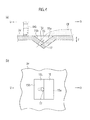
Fig. 6] Fig. 6 (a) is a lateral cross-sectional view of a turbine rotor blade according to a third embodiment along its chord direction, andFig. 6(b) is an enlarged cross-sectional view of a portion indicated by an arrow VIB shown inFig. 6 (a) . - A first embodiment will be explained with reference to
Figs. 1 to 4 . Note that "D" in the drawings indicates a downstream direction of combustion gas, and "U" indicates an upstream direction. - A
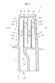
turbine rotor blade 1 according to the present embodiment is used in a turbine (not shown) of a gas turbine engine such as an aircraft engine and an industrial gas turbine engine. As shown inFigs. 1 and2 , theturbine rotor blade 1 is cooled by utilizing cooling air (portion of compressed air) CA extracted from a compressor (not shown) or a fan (not shown) of the gas turbine engine. - The
turbine rotor blade 1 is made by lost wax precision casting, and includes arotor blade body 3 that obtains a rotational force from combustion gas HG (seeFig. 3 ) from a combustor (not shown) of the gas turbine engine. In addition, aplatform 5 is integrally formed at a base end of therotor blade body 3. Adovetail 7 is integrally formed on theplatform 5. Thedovetail 7 is engaged with one of joint slots (not shown) formed around a turbine disc (not shown). - As shown in
Fig. 2 , anintroduction channel 9 into which the extracted cooling air CA is introduced is formed in an inside from thedovetail 7 to theplatform 5. In addition,plural partitions 11 extending along a span direction (a direction from theplatform 5 to anend face 3t of the rotor blade body 3) are formed in an inside of therotor blade body 3. Aserpentine cooling channel 13 in which the cooling air CA flows is partitioned by thepartitions 11. Namely, theserpentine cooling channel 13 is formed in an inside of therotor blade body 3, and communicates with theintroduction channel 9. - As shown in
Fig. 1 , plural bottomedrecesses 15 are formed on apressure surface 3v of therotor blade body 3. In the present embodiment, the bottomed recesses 15 are aligned in plural rows in a chord direction (a direction from aleading edge 3e to a trailingedge 3p of the rotor blade body 3), and each of the rows includes plural bottomed recesses 15. In addition, as shown inFig. 3(a) , eachdownstream wall 15a of the bottomed recesses 15 is inclined (inclined to a thickness direction T of the rotor blade body 3: inclined to a flow direction of the combustion gas: an angle between the downstream-sideinner wall 15a and thepressure surface 3v is obtuse), and eachupstream wall 15b of the bottomed recesses 15 is also inclined symmetrically (inclined to the thickness direction T: inclined to the flow direction of the combustion gas: an angle between the upstream-sideinner wall 15b and thepressure surface 3v is obtuse). Separated swirls can be made small by the inclination of the upstream-sideinner wall 15b when separations occur at the bottomed recesses 15, so that aerodynamic loss can be made small. - Note that at least one of an end edge of the downstream-side
inner wall 15a and an end edge of the upstream-sideinner wall 15b may be formed as a smoothly curved surface as shown inFig. 3(b) . Alternatively, the upstream-sideinner wall 15b may not be inclined but formed perpendicularly (parallel to the thickness direction T: perpendicular to the flow direction of the combustion gas: an angle between the upstream-sideinner wall 15b and thepressure surface 3v is orthogonal) as shown inFig. 3(c) . In this case, separations that may occur at the bottomed recesses 15 can be delayed (separation positions are shifted downstream), so that aerodynamic loss can be made smaller. - As shown in
Fig. 3 (a) [similarly also in the modified examples inFigs. 3(b) and 3(c) ], ejection holes (film-cooling holes) 17 each having a circular shape are formed on each bottom 15c (including a bottom-side of the upstream-sideinner wall 15b) of the bottomed recesses 15, and communicate with the coolingchannel 13. Each of the ejection holes 17 is formed so that acentral line 17L of theejection hole 17 extends almost along the downstream-sideinner wall 15a. Here, an inclined angle θ of thecentral line 17L to a plane (virtual plane) VP parallel to the downstream-sideinner wall 15a of the bottomedrecess 15 is set to equal-to or smaller-than ±20 degrees (-20 to +20 degrees). If the inclined angle θ is out of the range of ±20 degrees, Coanda effect by the cooling air CA ejected from the ejection holes 17 cannot be obtained sufficiently. - Note that a shape of the
ejection hole 17 may be another shape such as an ellipsoidal shape and a rectangular shape. In addition, as shown inFigs. 4(a) and 4(b) , it is preferable that a shape of theejection hole 17 is a diffuser hole which has a shape whose cross-sectional hole area (area on a cross-sectional plane perpendicular to a central axis of the hole) is made larger toward its outlet end. Namely, it is preferable that theejection hole 17 is a tapered hole gradually widened toward its outlet end. - As shown in
Fig. 1 , plural supplemental ejection holes 19 for ejecting the cooling air CA are formed on theleading edge 3e and theend face 3t of therotor blade body 3, and communicate with the coolingchannel 13. Plural eduction holes 21 for discharging the cooling air CA are formed on therailing edge 3p of therotor blade body 3, and communicate with the coolingchannel 13. - Note that plural supplemental ejection holes 19 may be formed also on a
suction surface 3b of therotor blade body 3 in addition to the supplemental ejection holes 19 formed on theleading edge 3e and thepressure surface 3v. - Next, advantages of the present embodiment will be explained.
- When cooling air CA flows into the cooling
channel 13 via theintroduction channel 9 during operation of the gas turbine engine, theturbine rotor blade 1 is cooled from its inside by a convective cooling (an internal cooling). In addition, the cooling air CA after the convective cooling is ejected from the ejection holes 17 and the supplemental ejection holes 19 to form the cooling film CF (seeFig. 3 (a) ) surrounding theturbine rotor blade 1. Theturbine rotor blade 1 is cooled from its outside by a film cooling (an external cooling) with the cooling film CF. Note that portion of the cooling air CA after the convective cooling for theturbine rotor blade 1 is ejected also from the eduction holes 21. - Since the downstream-side
inner walls 15a of the bottomed recesses 15 are inclined and thecentral lines 17L of the ejection holes 17 extends along the downstream-sideinner walls 15a, ejection angles of the cooling air CA from the ejection holes 15 can be made small without spoiling airfoil of theturbine rotor blade 1. As a result, Coanda effect by the cooling air CA can be obtained sufficiently. - In addition, since the downstream-side
inner walls 15a of the bottomed recesses 15 are inclined, striking of portion of the combustion gas HG on the downstream-sideinner walls 15a is mitigated and thereby separation of the combustion gas HG from the blade surface on a downstream side of the bottomedrecess 15 can be reduced. Especially, as shown inFig. 3(b) , the separation of the combustion gas HG from the blade surface can be further reduced in a case where an upper edge of the downstream-sideinner wall 15a is made as a smoothly curved surface. - Therefore, according to the present embodiment, cooling of the
turbine rotor blade 1 is improved and aerodynamic loss of theturbine rotor blade 1 is reduced, so that reduction of engine efficiency of the gas turbine engine can be restricted sufficiently. Especially, as shown inFigs. 4 (a) and 4 (b) , when a shape of the ejection hole(s) 17 is made so as to widen its internal shape, attachablity of the cooling air CA to thepressure surface 3v is made higher and thereby cooling of theturbine rotor blade 1 can be improved further. - A second embodiment will be explained with reference to
Fig. 5 . Note that "D" in the drawings indicates a downstream direction of combustion gas, and "U" indicates an upstream direction. - A
turbine rotor blade 23 in the present embodiment has almost the same configurations as those of theturbine rotor blade 1 in the above-explained first embodiment. Hereinafter, only configurations different from those of theturbine rotor blade 1 are explained, and configurations identical-to or similar-to those of theturbine rotor blade 1 are labeled with identical numerals and their explanations are omitted. - As-shown in
Fig. 5 , plural bottomed slots (one type of bottomed recess) 25 extending the span direction are formed on thepressure surface 3v of therotor blade body 3. Similarly to the above-explained bottomed recesses 15, each downstream-sideinner wall 25a of the bottomedslots 25 is inclined (inclined to the thickness direction T of the rotor blade body 3: inclined to the flow direction of the combustion gas: an angle between the downstream-sideinner wall 25a and thepressure surface 3v is obtuse), and each upstream-sideinner wall 25b of the bottomedslots 25 is also inclined symmetrically (inclined to the thickness direction T: inclined to the flow direction of the combustion gas: an angle between the upstream-sideinner wall 25b and thepressure surface 3v is obtuse). The above-explained plural ejection holes 17 are formed on each bottom 25c (including a bottom-side of the upstream-sideinner wall 25b) of the bottomedslots 25 at intervals along the span direction. Note that a cross-sectional shape of the bottomedslots 25 can be varied as explained in the first embodiment (seeFigs. 3(a) to 3(c) ), and a shape of theejection hole 17 can be also varied as explained in the first embodiment. - According to the present embodiment, in addition to the advantages by the first embodiment, the cooling air CA ejected from the plural ejection holes 17 can expands more easily along the span direction in each of the bottomed
slots 25, so that the cooling film CF can be formed more extensively. As a result, cooling of theturbine rotor blade 1 can be improved further. Further, in theturbine rotor blade 23 in the present embodiment, the number of the bottomed slots (one type of bottomed recess) 25 can be reduced in comparison with theturbine rotor blade 1 in the first embodiment, so that manufacturing costs becomes lower. - A third embodiment will be explained with reference to
Figs. 6 (a) and 6(b) . Note that "D" in the drawings indicates a downstream direction of combustion gas, and "U" indicates an upstream direction. - A
turbine rotor blade 27 in the present embodiment has almost the same configurations as those of theturbine rotor blade 1 in the above-explained first embodiment (or theturbine rotor blade 23 in the second embodiment). Hereinafter, only configurations different from those of theturbine rotor blade 1 are explained, and configurations identical-to or similar-to those of theturbine rotor blade 1 are labeled with identical numerals and their explanations are omitted. - As shown in
Figs. 6 (a) and 6(b), the bottomed recesses 15 explained in the first embodiment (or the bottomedslots 25 in the second embodiment) are formed, on thepressure surface 3v of theblade body 3, at positions associated with thepartitions 11. In addition, the ejection holes 17 in the bottomed recesses 17 (the bottomed slots 25) are located just upstream of thepartitions 11. - According to the present embodiment, in addition to the advantages by the first embodiment, affection to a shape of the cooling
channel 13 can be reduced even when the plural bottomedrecesses 15a are formed on thepressure surface 3v. More in detail, the bottomed recesses 15 protruding to the inside of the coolingchannel 13 are not formed at a center of the channel, so that the flow of the cooling air CA in the coolingchannel 13 becomes less impaired and manufacturing risks of the turbine blade by precision casting becomes low. In addition, since the bottomed recesses 15 (or the bottomed slots 25) are formed at the positions of thepartitions 11, risks for reducing strength and stiffness of theblade body 3 becomes low. Further, the cooling air CA after the convective cooling is smoothly ejected out from the ejection holes 17 by being guided by thepartitions 11. - Note that the present invention is not limited to the above embodiments, and, for example, the technical ideas applied to the turbine rotor blade 1 (23, 27) can be applied to engine components other than a turbine rotor blade, such as a turbine stator vane, a shroud, and a combustor liner.
Claims (9)
- A turbine blade that is used in a turbine of a gas turbine engine and cooled by cooling air, the blade comprising:a cooling channel that is formed within the turbine blade and in which the cooling air flows;a plurality of bottomed recesses that is formed on a blade surface of the turbine blade and of which each downstream-side inner wall is inclined; andan ejection hole that is formed on each bottom of the plurality of bottomed recesses and communicates with the cooling channel to eject the cooling air, whereinthe ejection hole is formed so that a central line of the ejection hole extends along the downstream-side inner wall.
- The turbine blade according to claim 1, wherein
an inclined angle of the central line of the ejection hole to a plane parallel to the downstream-side inner wall of the bottomed recess is set within a range of ±20 degrees. - The turbine blade according to claim 1 or 2, wherein
the ejection hole has a shape whose cross-sectional hole area is made larger toward an outlet end thereof. - The turbine blade according to any one of claims 1 to 3, wherein
at least one of the plurality of bottomed recesses is formed as a bottomed slot extending along a span direction, and a plurality of the ejection holes is formed at a bottom of the bottomed slot at intervals along the span direction. - The turbine blade according to any one of claims 1 to 4, wherein
each upstream-side inner wall of the ejection holes is inclined. - The turbine blade according to claim 5, wherein
at least one of an upper edge of the downstream-side inner wall and an upper edge of the upstream-side inner wall of the ejection hole is formed as a smoothly curved surface. - The turbine blade according to any one of claims 1 to 4, wherein
the upstream-side inner wall of the ejection hole is formed perpendicularly to the blade surface. - The turbine blade according to any one of claims 1 to 7, wherein
a partition extending a span direction is formed in an inside of the turbine blade, and the cooling channel is partitioned by the partition, and
at least one of the bottomed recesses is formed, on the blade surface, at a position associated with the partition. - An engine component that is used in a gas turbine engine and cooled by cooling air, the component comprising:a cooling channel that is formed within the engine component and in which the cooling air flows;a plurality of bottomed recesses that is formed on a surface of the engine component and of which each downstream-side inner wall is inclined; andan ejection hole that is formed on each bottom of the plurality of bottomed recesses and communicates with the cooling channel to eject the cooling air, whereinthe ejection hole is formed so that a central line of the ejection hole extends along the downstream-side inner wall.
Applications Claiming Priority (2)
| Application Number | Priority Date | Filing Date | Title |
|---|---|---|---|
| JP2010156949A JP5636774B2 (en) | 2010-07-09 | 2010-07-09 | Turbine blades and engine parts |
| PCT/JP2011/065580 WO2012005324A1 (en) | 2010-07-09 | 2011-07-07 | Turbine blade and engine component |
Publications (3)
| Publication Number | Publication Date |
|---|---|
| EP2592228A1 true EP2592228A1 (en) | 2013-05-15 |
| EP2592228A4 EP2592228A4 (en) | 2016-04-20 |
| EP2592228B1 EP2592228B1 (en) | 2019-08-21 |
Family
ID=45441301
Family Applications (1)
| Application Number | Title | Priority Date | Filing Date |
|---|---|---|---|
| EP11803658.1A Active EP2592228B1 (en) | 2010-07-09 | 2011-07-07 | Turbine blade and engine component |
Country Status (7)
| Country | Link |
|---|---|
| US (1) | US9376919B2 (en) |
| EP (1) | EP2592228B1 (en) |
| JP (1) | JP5636774B2 (en) |
| KR (1) | KR101434926B1 (en) |
| CN (1) | CN102971493B (en) |
| CA (1) | CA2804632C (en) |
| WO (1) | WO2012005324A1 (en) |
Cited By (4)
| Publication number | Priority date | Publication date | Assignee | Title |
|---|---|---|---|---|
| EP3064707A1 (en) * | 2015-02-27 | 2016-09-07 | General Electric Company | Engine component |
| EP3133247A1 (en) * | 2015-08-19 | 2017-02-22 | General Electric Company | Engine component for a gas turbine engine |
| US10024169B2 (en) | 2015-02-27 | 2018-07-17 | General Electric Company | Engine component |
| EP4435230A1 (en) * | 2023-03-23 | 2024-09-25 | Doosan Enerbility Co., Ltd. | Blade for a gas turbine, turbine blade assembly and gas turbine |
Families Citing this family (26)
| Publication number | Priority date | Publication date | Assignee | Title |
|---|---|---|---|---|
| US8870535B2 (en) * | 2012-01-13 | 2014-10-28 | General Electric Company | Airfoil |
| US8870536B2 (en) * | 2012-01-13 | 2014-10-28 | General Electric Company | Airfoil |
| JP2014148938A (en) * | 2013-02-01 | 2014-08-21 | Siemens Ag | Film-cooled turbine blade for turbomachine |
| WO2014137470A1 (en) * | 2013-03-05 | 2014-09-12 | Vandervaart Peter L | Gas turbine engine component arrangement |
| WO2014163698A1 (en) | 2013-03-07 | 2014-10-09 | Vandervaart Peter L | Cooled gas turbine engine component |
| GB201315871D0 (en) | 2013-09-06 | 2013-10-23 | Rolls Royce Plc | A combustion chamber arrangement |
| KR101839656B1 (en) * | 2015-08-13 | 2018-04-26 | 두산중공업 주식회사 | Blade for turbine |
| US20170306764A1 (en) * | 2016-04-26 | 2017-10-26 | General Electric Company | Airfoil for a turbine engine |
| US10309227B2 (en) * | 2016-10-26 | 2019-06-04 | General Electric Company | Multi-turn cooling circuits for turbine blades |
| US10233761B2 (en) | 2016-10-26 | 2019-03-19 | General Electric Company | Turbine airfoil trailing edge coolant passage created by cover |
| US10465521B2 (en) | 2016-10-26 | 2019-11-05 | General Electric Company | Turbine airfoil coolant passage created in cover |
| US10450875B2 (en) | 2016-10-26 | 2019-10-22 | General Electric Company | Varying geometries for cooling circuits of turbine blades |
| US10352176B2 (en) | 2016-10-26 | 2019-07-16 | General Electric Company | Cooling circuits for a multi-wall blade |
| US10301946B2 (en) | 2016-10-26 | 2019-05-28 | General Electric Company | Partially wrapped trailing edge cooling circuits with pressure side impingements |
| US10598028B2 (en) | 2016-10-26 | 2020-03-24 | General Electric Company | Edge coupon including cooling circuit for airfoil |
| US10273810B2 (en) | 2016-10-26 | 2019-04-30 | General Electric Company | Partially wrapped trailing edge cooling circuit with pressure side serpentine cavities |
| US10450950B2 (en) | 2016-10-26 | 2019-10-22 | General Electric Company | Turbomachine blade with trailing edge cooling circuit |
| CN106593543B (en) * | 2016-11-28 | 2018-04-17 | 西北工业大学 | A kind of arch form groove gaseous film control structure for turbo blade |
| CN108995818A (en) * | 2017-06-07 | 2018-12-14 | 深圳光启合众科技有限公司 | Ducted fan |
| US11149555B2 (en) | 2017-06-14 | 2021-10-19 | General Electric Company | Turbine engine component with deflector |
| US10801724B2 (en) * | 2017-06-14 | 2020-10-13 | General Electric Company | Method and apparatus for minimizing cross-flow across an engine cooling hole |
| US10837291B2 (en) | 2017-11-17 | 2020-11-17 | General Electric Company | Turbine engine with component having a cooled tip |
| US10669896B2 (en) * | 2018-01-17 | 2020-06-02 | Raytheon Technologies Corporation | Dirt separator for internally cooled components |
| US11220917B1 (en) | 2020-09-03 | 2022-01-11 | Raytheon Technologies Corporation | Diffused cooling arrangement for gas turbine engine components |
| CN112282855B (en) * | 2020-09-27 | 2022-08-16 | 哈尔滨工业大学 | Turbine blade |
| US11814965B2 (en) | 2021-11-10 | 2023-11-14 | General Electric Company | Turbomachine blade trailing edge cooling circuit with turn passage having set of obstructions |
Family Cites Families (16)
| Publication number | Priority date | Publication date | Assignee | Title |
|---|---|---|---|---|
| US4738588A (en) | 1985-12-23 | 1988-04-19 | Field Robert E | Film cooling passages with step diffuser |
| US4676719A (en) | 1985-12-23 | 1987-06-30 | United Technologies Corporation | Film coolant passages for cast hollow airfoils |
| US4773593A (en) * | 1987-05-04 | 1988-09-27 | United Technologies Corporation | Coolable thin metal sheet |
| US5419681A (en) * | 1993-01-25 | 1995-05-30 | General Electric Company | Film cooled wall |
| JPH09144504A (en) * | 1995-11-22 | 1997-06-03 | Ishikawajima Harima Heavy Ind Co Ltd | Turbine cooling blade and its working method |
| US5813836A (en) * | 1996-12-24 | 1998-09-29 | General Electric Company | Turbine blade |
| US6234755B1 (en) | 1999-10-04 | 2001-05-22 | General Electric Company | Method for improving the cooling effectiveness of a gaseous coolant stream, and related articles of manufacture |
| GB0001399D0 (en) * | 2000-01-22 | 2000-03-08 | Rolls Royce Plc | An aerofoil for an axial flow turbomachine |
| JP2002221005A (en) | 2001-01-26 | 2002-08-09 | Ishikawajima Harima Heavy Ind Co Ltd | Cooling turbine blade |
| US6547524B2 (en) * | 2001-05-21 | 2003-04-15 | United Technologies Corporation | Film cooled article with improved temperature tolerance |
| US6629817B2 (en) | 2001-07-05 | 2003-10-07 | General Electric Company | System and method for airfoil film cooling |
| US7008179B2 (en) * | 2003-12-16 | 2006-03-07 | General Electric Co. | Turbine blade frequency tuned pin bank |
| US7011502B2 (en) * | 2004-04-15 | 2006-03-14 | General Electric Company | Thermal shield turbine airfoil |
| US7270514B2 (en) * | 2004-10-21 | 2007-09-18 | General Electric Company | Turbine blade tip squealer and rebuild method |
| US7306026B2 (en) * | 2005-09-01 | 2007-12-11 | United Technologies Corporation | Cooled turbine airfoils and methods of manufacture |
| DE102007029367A1 (en) | 2007-06-26 | 2009-01-02 | Rolls-Royce Deutschland Ltd & Co Kg | Shovel with tangential jet generation on the profile |
-
2010
- 2010-07-09 JP JP2010156949A patent/JP5636774B2/en active Active
-
2011
- 2011-07-07 US US13/808,641 patent/US9376919B2/en active Active
- 2011-07-07 CN CN201180033360.6A patent/CN102971493B/en not_active Expired - Fee Related
- 2011-07-07 KR KR1020137001551A patent/KR101434926B1/en active IP Right Grant
- 2011-07-07 EP EP11803658.1A patent/EP2592228B1/en active Active
- 2011-07-07 WO PCT/JP2011/065580 patent/WO2012005324A1/en active Application Filing
- 2011-07-07 CA CA2804632A patent/CA2804632C/en active Active
Cited By (8)
| Publication number | Priority date | Publication date | Assignee | Title |
|---|---|---|---|---|
| EP3064707A1 (en) * | 2015-02-27 | 2016-09-07 | General Electric Company | Engine component |
| US10024169B2 (en) | 2015-02-27 | 2018-07-17 | General Electric Company | Engine component |
| US10132166B2 (en) | 2015-02-27 | 2018-11-20 | General Electric Company | Engine component |
| EP3133247A1 (en) * | 2015-08-19 | 2017-02-22 | General Electric Company | Engine component for a gas turbine engine |
| CN106468180A (en) * | 2015-08-19 | 2017-03-01 | 通用电气公司 | Engine component for gas-turbine unit |
| US10378444B2 (en) | 2015-08-19 | 2019-08-13 | General Electric Company | Engine component for a gas turbine engine |
| CN106468180B (en) * | 2015-08-19 | 2020-03-27 | 通用电气公司 | Engine component for a gas turbine engine |
| EP4435230A1 (en) * | 2023-03-23 | 2024-09-25 | Doosan Enerbility Co., Ltd. | Blade for a gas turbine, turbine blade assembly and gas turbine |
Also Published As
| Publication number | Publication date |
|---|---|
| EP2592228A4 (en) | 2016-04-20 |
| US20130108471A1 (en) | 2013-05-02 |
| CN102971493A (en) | 2013-03-13 |
| CA2804632C (en) | 2016-02-16 |
| US9376919B2 (en) | 2016-06-28 |
| WO2012005324A1 (en) | 2012-01-12 |
| KR20130023353A (en) | 2013-03-07 |
| JP2012017721A (en) | 2012-01-26 |
| EP2592228B1 (en) | 2019-08-21 |
| CA2804632A1 (en) | 2012-01-12 |
| CN102971493B (en) | 2015-08-05 |
| KR101434926B1 (en) | 2014-08-27 |
| JP5636774B2 (en) | 2014-12-10 |
Similar Documents
| Publication | Publication Date | Title |
|---|---|---|
| EP2592228B1 (en) | Turbine blade and engine component | |
| US10822957B2 (en) | Fillet optimization for turbine airfoil | |
| EP2616642B1 (en) | Turbine component with multi-scale turbulation features | |
| US10436040B2 (en) | Airfoil with dual-wall cooling for a gas turbine engine | |
| EP2154333B1 (en) | Airfoil and corresponding turbine assembly | |
| EP1873354B1 (en) | Leading edge cooling using chevron trip strips | |
| US8668453B2 (en) | Cooling system having reduced mass pin fins for components in a gas turbine engine | |
| EP1870561B1 (en) | Leading edge cooling of a gas turbine component using staggered turbulator strips | |
| JP5977884B2 (en) | Asymmetrical trailing edge cooling hole | |
| CN1840859B (en) | Turbine airfoil with trailing edge convection | |
| JP2006077767A (en) | Offset coriolis turbulator blade | |
| US7300242B2 (en) | Turbine airfoil with integral cooling system | |
| US9631499B2 (en) | Turbine airfoil cooling system for bow vane | |
| US9581029B2 (en) | High pressure turbine blade cooling hole distribution | |
| EP2738350B1 (en) | Turbine blade airfoils including showerhead film cooling systems, and methods for forming an improved showerhead film cooled airfoil of a turbine blade | |
| EP3006670A2 (en) | Turbine blades and methods of forming turbine blades having lifted rib turbulator structures | |
| CA2868536C (en) | Turbine airfoil trailing edge cooling slots | |
| WO2012137898A1 (en) | Turbine vane | |
| US20110044822A1 (en) | Gas turbine blade and gas turbine having the same | |
| WO2014011276A2 (en) | Turbine airfoil trailing edge bifurcated cooling holes | |
| CN109154200B (en) | Airfoil and blade for a turbine engine, and corresponding method of flowing a cooling fluid |
Legal Events
| Date | Code | Title | Description |
|---|---|---|---|
| PUAI | Public reference made under article 153(3) epc to a published international application that has entered the european phase |
Free format text: ORIGINAL CODE: 0009012 |
|
| 17P | Request for examination filed |
Effective date: 20130103 |
|
| AK | Designated contracting states |
Kind code of ref document: A1 Designated state(s): AL AT BE BG CH CY CZ DE DK EE ES FI FR GB GR HR HU IE IS IT LI LT LU LV MC MK MT NL NO PL PT RO RS SE SI SK SM TR |
|
| DAX | Request for extension of the european patent (deleted) | ||
| RA4 | Supplementary search report drawn up and despatched (corrected) |
Effective date: 20160321 |
|
| RIC1 | Information provided on ipc code assigned before grant |
Ipc: F02C 7/18 20060101ALI20160315BHEP Ipc: F01D 5/18 20060101AFI20160315BHEP Ipc: F01D 9/02 20060101ALI20160315BHEP |
|
| STAA | Information on the status of an ep patent application or granted ep patent |
Free format text: STATUS: EXAMINATION IS IN PROGRESS |
|
| 17Q | First examination report despatched |
Effective date: 20180711 |
|
| GRAP | Despatch of communication of intention to grant a patent |
Free format text: ORIGINAL CODE: EPIDOSNIGR1 |
|
| STAA | Information on the status of an ep patent application or granted ep patent |
Free format text: STATUS: GRANT OF PATENT IS INTENDED |
|
| INTG | Intention to grant announced |
Effective date: 20190219 |
|
| GRAS | Grant fee paid |
Free format text: ORIGINAL CODE: EPIDOSNIGR3 |
|
| GRAJ | Information related to disapproval of communication of intention to grant by the applicant or resumption of examination proceedings by the epo deleted |
Free format text: ORIGINAL CODE: EPIDOSDIGR1 |
|
| GRAL | Information related to payment of fee for publishing/printing deleted |
Free format text: ORIGINAL CODE: EPIDOSDIGR3 |
|
| STAA | Information on the status of an ep patent application or granted ep patent |
Free format text: STATUS: EXAMINATION IS IN PROGRESS |
|
| GRAR | Information related to intention to grant a patent recorded |
Free format text: ORIGINAL CODE: EPIDOSNIGR71 |
|
| STAA | Information on the status of an ep patent application or granted ep patent |
Free format text: STATUS: GRANT OF PATENT IS INTENDED |
|
| INTC | Intention to grant announced (deleted) | ||
| GRAA | (expected) grant |
Free format text: ORIGINAL CODE: 0009210 |
|
| STAA | Information on the status of an ep patent application or granted ep patent |
Free format text: STATUS: THE PATENT HAS BEEN GRANTED |
|
| INTG | Intention to grant announced |
Effective date: 20190627 |
|
| AK | Designated contracting states |
Kind code of ref document: B1 Designated state(s): AL AT BE BG CH CY CZ DE DK EE ES FI FR GB GR HR HU IE IS IT LI LT LU LV MC MK MT NL NO PL PT RO RS SE SI SK SM TR |
|
| REG | Reference to a national code |
Ref country code: GB Ref legal event code: FG4D |
|
| REG | Reference to a national code |
Ref country code: CH Ref legal event code: EP |
|
| REG | Reference to a national code |
Ref country code: DE Ref legal event code: R096 Ref document number: 602011061466 Country of ref document: DE |
|
| REG | Reference to a national code |
Ref country code: AT Ref legal event code: REF Ref document number: 1169981 Country of ref document: AT Kind code of ref document: T Effective date: 20190915 |
|
| REG | Reference to a national code |
Ref country code: IE Ref legal event code: FG4D |
|
| REG | Reference to a national code |
Ref country code: SE Ref legal event code: TRGR |
|
| REG | Reference to a national code |
Ref country code: LT Ref legal event code: MG4D |
|
| REG | Reference to a national code |
Ref country code: NL Ref legal event code: MP Effective date: 20190821 |
|
| PG25 | Lapsed in a contracting state [announced via postgrant information from national office to epo] |
Ref country code: HR Free format text: LAPSE BECAUSE OF FAILURE TO SUBMIT A TRANSLATION OF THE DESCRIPTION OR TO PAY THE FEE WITHIN THE PRESCRIBED TIME-LIMIT Effective date: 20190821 Ref country code: NL Free format text: LAPSE BECAUSE OF FAILURE TO SUBMIT A TRANSLATION OF THE DESCRIPTION OR TO PAY THE FEE WITHIN THE PRESCRIBED TIME-LIMIT Effective date: 20190821 Ref country code: BG Free format text: LAPSE BECAUSE OF FAILURE TO SUBMIT A TRANSLATION OF THE DESCRIPTION OR TO PAY THE FEE WITHIN THE PRESCRIBED TIME-LIMIT Effective date: 20191121 Ref country code: LT Free format text: LAPSE BECAUSE OF FAILURE TO SUBMIT A TRANSLATION OF THE DESCRIPTION OR TO PAY THE FEE WITHIN THE PRESCRIBED TIME-LIMIT Effective date: 20190821 Ref country code: PT Free format text: LAPSE BECAUSE OF FAILURE TO SUBMIT A TRANSLATION OF THE DESCRIPTION OR TO PAY THE FEE WITHIN THE PRESCRIBED TIME-LIMIT Effective date: 20191223 Ref country code: NO Free format text: LAPSE BECAUSE OF FAILURE TO SUBMIT A TRANSLATION OF THE DESCRIPTION OR TO PAY THE FEE WITHIN THE PRESCRIBED TIME-LIMIT Effective date: 20191121 Ref country code: FI Free format text: LAPSE BECAUSE OF FAILURE TO SUBMIT A TRANSLATION OF THE DESCRIPTION OR TO PAY THE FEE WITHIN THE PRESCRIBED TIME-LIMIT Effective date: 20190821 |
|
| PG25 | Lapsed in a contracting state [announced via postgrant information from national office to epo] |
Ref country code: IS Free format text: LAPSE BECAUSE OF FAILURE TO SUBMIT A TRANSLATION OF THE DESCRIPTION OR TO PAY THE FEE WITHIN THE PRESCRIBED TIME-LIMIT Effective date: 20191221 Ref country code: RS Free format text: LAPSE BECAUSE OF FAILURE TO SUBMIT A TRANSLATION OF THE DESCRIPTION OR TO PAY THE FEE WITHIN THE PRESCRIBED TIME-LIMIT Effective date: 20190821 Ref country code: ES Free format text: LAPSE BECAUSE OF FAILURE TO SUBMIT A TRANSLATION OF THE DESCRIPTION OR TO PAY THE FEE WITHIN THE PRESCRIBED TIME-LIMIT Effective date: 20190821 Ref country code: GR Free format text: LAPSE BECAUSE OF FAILURE TO SUBMIT A TRANSLATION OF THE DESCRIPTION OR TO PAY THE FEE WITHIN THE PRESCRIBED TIME-LIMIT Effective date: 20191122 Ref country code: AL Free format text: LAPSE BECAUSE OF FAILURE TO SUBMIT A TRANSLATION OF THE DESCRIPTION OR TO PAY THE FEE WITHIN THE PRESCRIBED TIME-LIMIT Effective date: 20190821 Ref country code: LV Free format text: LAPSE BECAUSE OF FAILURE TO SUBMIT A TRANSLATION OF THE DESCRIPTION OR TO PAY THE FEE WITHIN THE PRESCRIBED TIME-LIMIT Effective date: 20190821 |
|
| REG | Reference to a national code |
Ref country code: AT Ref legal event code: MK05 Ref document number: 1169981 Country of ref document: AT Kind code of ref document: T Effective date: 20190821 |
|
| PG25 | Lapsed in a contracting state [announced via postgrant information from national office to epo] |
Ref country code: TR Free format text: LAPSE BECAUSE OF FAILURE TO SUBMIT A TRANSLATION OF THE DESCRIPTION OR TO PAY THE FEE WITHIN THE PRESCRIBED TIME-LIMIT Effective date: 20190821 |
|
| PG25 | Lapsed in a contracting state [announced via postgrant information from national office to epo] |
Ref country code: PL Free format text: LAPSE BECAUSE OF FAILURE TO SUBMIT A TRANSLATION OF THE DESCRIPTION OR TO PAY THE FEE WITHIN THE PRESCRIBED TIME-LIMIT Effective date: 20190821 Ref country code: DK Free format text: LAPSE BECAUSE OF FAILURE TO SUBMIT A TRANSLATION OF THE DESCRIPTION OR TO PAY THE FEE WITHIN THE PRESCRIBED TIME-LIMIT Effective date: 20190821 Ref country code: EE Free format text: LAPSE BECAUSE OF FAILURE TO SUBMIT A TRANSLATION OF THE DESCRIPTION OR TO PAY THE FEE WITHIN THE PRESCRIBED TIME-LIMIT Effective date: 20190821 Ref country code: AT Free format text: LAPSE BECAUSE OF FAILURE TO SUBMIT A TRANSLATION OF THE DESCRIPTION OR TO PAY THE FEE WITHIN THE PRESCRIBED TIME-LIMIT Effective date: 20190821 Ref country code: RO Free format text: LAPSE BECAUSE OF FAILURE TO SUBMIT A TRANSLATION OF THE DESCRIPTION OR TO PAY THE FEE WITHIN THE PRESCRIBED TIME-LIMIT Effective date: 20190821 |
|
| PG25 | Lapsed in a contracting state [announced via postgrant information from national office to epo] |
Ref country code: SM Free format text: LAPSE BECAUSE OF FAILURE TO SUBMIT A TRANSLATION OF THE DESCRIPTION OR TO PAY THE FEE WITHIN THE PRESCRIBED TIME-LIMIT Effective date: 20190821 Ref country code: SK Free format text: LAPSE BECAUSE OF FAILURE TO SUBMIT A TRANSLATION OF THE DESCRIPTION OR TO PAY THE FEE WITHIN THE PRESCRIBED TIME-LIMIT Effective date: 20190821 Ref country code: IS Free format text: LAPSE BECAUSE OF FAILURE TO SUBMIT A TRANSLATION OF THE DESCRIPTION OR TO PAY THE FEE WITHIN THE PRESCRIBED TIME-LIMIT Effective date: 20200224 Ref country code: CZ Free format text: LAPSE BECAUSE OF FAILURE TO SUBMIT A TRANSLATION OF THE DESCRIPTION OR TO PAY THE FEE WITHIN THE PRESCRIBED TIME-LIMIT Effective date: 20190821 |
|
| REG | Reference to a national code |
Ref country code: DE Ref legal event code: R097 Ref document number: 602011061466 Country of ref document: DE |
|
| PLBE | No opposition filed within time limit |
Free format text: ORIGINAL CODE: 0009261 |
|
| STAA | Information on the status of an ep patent application or granted ep patent |
Free format text: STATUS: NO OPPOSITION FILED WITHIN TIME LIMIT |
|
| PG2D | Information on lapse in contracting state deleted |
Ref country code: IS |
|
| 26N | No opposition filed |
Effective date: 20200603 |
|
| PG25 | Lapsed in a contracting state [announced via postgrant information from national office to epo] |
Ref country code: SI Free format text: LAPSE BECAUSE OF FAILURE TO SUBMIT A TRANSLATION OF THE DESCRIPTION OR TO PAY THE FEE WITHIN THE PRESCRIBED TIME-LIMIT Effective date: 20190821 |
|
| PG25 | Lapsed in a contracting state [announced via postgrant information from national office to epo] |
Ref country code: MC Free format text: LAPSE BECAUSE OF FAILURE TO SUBMIT A TRANSLATION OF THE DESCRIPTION OR TO PAY THE FEE WITHIN THE PRESCRIBED TIME-LIMIT Effective date: 20190821 |
|
| REG | Reference to a national code |
Ref country code: CH Ref legal event code: PL |
|
| REG | Reference to a national code |
Ref country code: BE Ref legal event code: MM Effective date: 20200731 |
|
| PG25 | Lapsed in a contracting state [announced via postgrant information from national office to epo] |
Ref country code: CH Free format text: LAPSE BECAUSE OF NON-PAYMENT OF DUE FEES Effective date: 20200731 Ref country code: IE Free format text: LAPSE BECAUSE OF NON-PAYMENT OF DUE FEES Effective date: 20200707 Ref country code: LI Free format text: LAPSE BECAUSE OF NON-PAYMENT OF DUE FEES Effective date: 20200731 Ref country code: LU Free format text: LAPSE BECAUSE OF NON-PAYMENT OF DUE FEES Effective date: 20200707 |
|
| PG25 | Lapsed in a contracting state [announced via postgrant information from national office to epo] |
Ref country code: BE Free format text: LAPSE BECAUSE OF NON-PAYMENT OF DUE FEES Effective date: 20200731 |
|
| PG25 | Lapsed in a contracting state [announced via postgrant information from national office to epo] |
Ref country code: MT Free format text: LAPSE BECAUSE OF FAILURE TO SUBMIT A TRANSLATION OF THE DESCRIPTION OR TO PAY THE FEE WITHIN THE PRESCRIBED TIME-LIMIT Effective date: 20190821 Ref country code: CY Free format text: LAPSE BECAUSE OF FAILURE TO SUBMIT A TRANSLATION OF THE DESCRIPTION OR TO PAY THE FEE WITHIN THE PRESCRIBED TIME-LIMIT Effective date: 20190821 |
|
| PG25 | Lapsed in a contracting state [announced via postgrant information from national office to epo] |
Ref country code: MK Free format text: LAPSE BECAUSE OF FAILURE TO SUBMIT A TRANSLATION OF THE DESCRIPTION OR TO PAY THE FEE WITHIN THE PRESCRIBED TIME-LIMIT Effective date: 20190821 |
|
| PGFP | Annual fee paid to national office [announced via postgrant information from national office to epo] |
Ref country code: SE Payment date: 20220622 Year of fee payment: 12 Ref country code: IT Payment date: 20220621 Year of fee payment: 12 |
|
| PGFP | Annual fee paid to national office [announced via postgrant information from national office to epo] |
Ref country code: FR Payment date: 20220621 Year of fee payment: 12 |
|
| PGFP | Annual fee paid to national office [announced via postgrant information from national office to epo] |
Ref country code: DE Payment date: 20220621 Year of fee payment: 12 |
|
| REG | Reference to a national code |
Ref country code: DE Ref legal event code: R119 Ref document number: 602011061466 Country of ref document: DE |
|
| REG | Reference to a national code |
Ref country code: SE Ref legal event code: EUG |
|
| PG25 | Lapsed in a contracting state [announced via postgrant information from national office to epo] |
Ref country code: DE Free format text: LAPSE BECAUSE OF NON-PAYMENT OF DUE FEES Effective date: 20240201 |
|
| PG25 | Lapsed in a contracting state [announced via postgrant information from national office to epo] |
Ref country code: SE Free format text: LAPSE BECAUSE OF NON-PAYMENT OF DUE FEES Effective date: 20230708 Ref country code: FR Free format text: LAPSE BECAUSE OF NON-PAYMENT OF DUE FEES Effective date: 20230731 |
|
| PGFP | Annual fee paid to national office [announced via postgrant information from national office to epo] |
Ref country code: GB Payment date: 20240620 Year of fee payment: 14 |
|
| PG25 | Lapsed in a contracting state [announced via postgrant information from national office to epo] |
Ref country code: IT Free format text: LAPSE BECAUSE OF NON-PAYMENT OF DUE FEES Effective date: 20230707 |