EP2592200B1 - Anpassbare Mitnehmer- oder Anschlaganordnung - Google Patents
Anpassbare Mitnehmer- oder Anschlaganordnung Download PDFInfo
- Publication number
- EP2592200B1 EP2592200B1 EP12192134.0A EP12192134A EP2592200B1 EP 2592200 B1 EP2592200 B1 EP 2592200B1 EP 12192134 A EP12192134 A EP 12192134A EP 2592200 B1 EP2592200 B1 EP 2592200B1
- Authority
- EP
- European Patent Office
- Prior art keywords
- backplate
- faceplate
- assembly according
- screw
- assembly
- Prior art date
- Legal status (The legal status is an assumption and is not a legal conclusion. Google has not performed a legal analysis and makes no representation as to the accuracy of the status listed.)
- Active
Links
Images

Classifications
-
- E—FIXED CONSTRUCTIONS
- E05—LOCKS; KEYS; WINDOW OR DOOR FITTINGS; SAFES
- E05B—LOCKS; ACCESSORIES THEREFOR; HANDCUFFS
- E05B15/00—Other details of locks; Parts for engagement by bolts of fastening devices
- E05B15/02—Striking-plates; Keepers; Bolt staples; Escutcheons
- E05B15/0205—Striking-plates, keepers, staples
- E05B15/024—Striking-plates, keepers, staples adjustable
- E05B15/0245—Movable elements held by friction, cooperating teeth, or the like
-
- E—FIXED CONSTRUCTIONS
- E05—LOCKS; KEYS; WINDOW OR DOOR FITTINGS; SAFES
- E05B—LOCKS; ACCESSORIES THEREFOR; HANDCUFFS
- E05B15/00—Other details of locks; Parts for engagement by bolts of fastening devices
- E05B15/02—Striking-plates; Keepers; Bolt staples; Escutcheons
- E05B15/0205—Striking-plates, keepers, staples
- E05B15/024—Striking-plates, keepers, staples adjustable
- E05B15/025—Striking-plates, keepers, staples adjustable the striker being movable by a screw/nut
-
- E—FIXED CONSTRUCTIONS
- E05—LOCKS; KEYS; WINDOW OR DOOR FITTINGS; SAFES
- E05B—LOCKS; ACCESSORIES THEREFOR; HANDCUFFS
- E05B15/00—Other details of locks; Parts for engagement by bolts of fastening devices
- E05B15/02—Striking-plates; Keepers; Bolt staples; Escutcheons
- E05B15/0205—Striking-plates, keepers, staples
- E05B15/024—Striking-plates, keepers, staples adjustable
- E05B2015/0275—Striking-plates, keepers, staples adjustable in two directions
Definitions
- This invention relates to adjustable strike or keep assemblies and to frame assemblies on which such strike or keep assemblies are mounted.
- a "strike or keep” it should be understood that the item referred to may be both a strike and a keep or may be either a strike or a keep.
- US4288120A discloses an improved door latch assembly having a striker plate with an adjustable locking notch.
- the adjustable locking notch is provided by an adjustable slide member mounted in sliding relationship to the striker plate and having threaded adjustment means.
- a strike or keep assembly comprises a faceplate, a backplate including a body portion having a planar front face butting up against a planar back face of the faceplate and one or more projecting portions for extending rearwardly from the body portion of the backplate into contact with a face of a supporting frame, a screw-threaded member in screw threaded engagement with a threaded hole in the faceplate and extending rearwardly for contacting the face of the supporting frame, the faceplate including one or more slots for allowing the passage of one or more fasteners for engaging one or more fastener locations in the backplate to fasten the backplate to the faceplate.
- the screw-threaded member can be used to level the faceplate while the slots in the faceplate provide a facility for lateral adjustment of the faceplate relative to the backplate; that enables a reasonably comprehensive and easy adjustment of the faceplate to be achieved simply, without special tools, and economically on a wide range of frame profiles which vary widely in terms of their shapes, dimensions and materials.
- a strike or keep assembly is, in use, mounted on a support frame which may define a door or window opening.
- a support frame has a longitudinal axis extending parallel to the edge of the opening; in the case of a door, the longitudinal axis will normally be a vertical axis; in the case of a window, that may also be the case or the longitudinal axis may be a horizontal axis.
- the axis referred to is one parallel to the longitudinal axis of the support frame referred to above.
- the faceplate will be of longest dimension along that axis, substantially shorter in an orthogonal direction across the width of the front face of the faceplate, and substantially shorter again in the orthogonal direction perpendicular to the front face of the faceplate, the precise details of the faceplate depending upon the particular application.
- the backplate may often be of square or almost square shape with the length and width of the backplate of comparable magnitude and substantially greater than its thickness. If desired, one faceplate may be provided with more than one backplate, the backplates being spaced along the longitudinal axis of the faceplate.
- the one or more projecting portions may be provided by one or more separate parts fixed to the body portion or adjustably mounted on the body portion; for example, the one or more separate parts could be grub screws adjustably or non-adjustably fitted to the backplate; more preferably, however, the one or more projecting portions are integral with the body portion of the backplate. That reduces the total number of parts required.
- the one or more projecting portions may be formed by bending of one or more portions of the backplate to form one or more wall portions, or they may be formed in other ways, for example by casting of the backplate with the one or more projections formed during the casting.
- each of the one or more wall portions is arranged for contacting the support frame along the length of a distal edge portion.
- the one or more wall portions comprise a single wall formed by bending a longitudinal edge portion of the backplate; that is a particularly simple, reliable and economical way of providing the one or more projecting portions.
- the edge portion is bent through about ninety degrees but other angles of bending may also be adopted.
- the screw-threaded member is preferably a grub screw.
- the screw threaded member passes through the faceplate and extends rearwardly to the face of a supporting frame; the body portion of the backplate may include an opening through which the screw-threaded member may pass with clearance.
- the opening may be open at an edge of the backplate or be enclosed. It may be of circular shape but in a preferred embodiment it is a slot shape. That is the arrangement adopted in an embodiment of the invention described below; it is, however, also within the scope of the invention for the screw-threaded member to pass to one side of the backplate. Also more than one screw-threaded member may be provided if desired.
- an opposite longitudinal edge portion of the backplate is preferably provided with an open-ended slot for accommodating the screw-threaded member.
- Each of the one or more slots in the faceplate is preferably elongate and is preferably longer in a direction transverse to its longitudinal axis; that facilitates transverse adjustment of the faceplate relative to the backplate.
- the faceplate has two slots for allowing the passage of two fasteners for engaging two fastener locations in the backplate to fasten the backplate to the faceplate.
- the two slots are longitudinally spaced along the faceplate.
- the faceplate is provided with other openings by which it can be secured to the supporting frame, and also other openings for receiving a locking or latching member of an openable unit, which may be, for example, a door or a window.
- the faceplate is preferably provided with longitudinally extending lips along its opposite side edges, the lips extending rearwardly from the front face of the faceplate. Such lips may be formed by bending over the opposite side edges of a planar blank.
- the invention also provides a frame assembly including a supporting frame member and a strike or keep assembly as defined above mounted on the supporting frame member, the one or more projecting portions of the backplate extending rearwardly from the body portion of the backplate into contact with a planar face of the supporting frame member, the screw-threaded member extending rearwardly from the faceplate through or past the backplate into contact with the planar face of the supporting frame member, and one or more fasteners passing through the one or more slots and engaging one or more fastener locations in the backplate to fasten the backplate to the faceplate.
- the supporting frame member may be solid but will more often be in the form of a metal and/or plastics extruded profile.
- the member may be an extruded UPVC member which may be metal reinforced.
- the member may have a longitudinally extending edge against which the backplate may be placed to facilitate alignment of the backplate in a desired position laterally.
- the backplate has one or more wall portions, the one or more wall portions are preferably placed against the edge.
- the lips may rest on portions of the frame member that are positioned forwardly of its planar face.
- the keep or strike assembly according to the invention can also be provided as a kit of parts to be assembled. Accordingly, the invention further provides a faceplate, a backplate and a screw-threaded member for assembling into a strike or keep assembly as defined above.
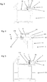
- Fig. 1 shows part of one side of a door frame.
- the door frame shown is in this example part of a UPVC door frame and the drawing shows a small length of a frame profile 1, which may be found as a single extrusion or a plurality of interengaging extrusions.
- the profile 1 extends vertically along the entire length of the doorway and Fig. 1 shows just a small portion of the vertical extent of the profile 1.
- an adjustable keep assembly 2 is fitted.
- the keep assembly 2 is part of a multipoint locking system, and includes recesses 3 and 4 for receiving respective locking members of a multipoint lock.
- the keep assembly 2 has end portions 2A and 2B and Fig. 2 is an exploded view of the end portion 2A of the keep assembly.
- Fig. 2 is an exploded view of the end portion 2A of the keep assembly.
- a faceplate 5 a backplate 6, a grub screw 7 and two button head screws 8A and 8B.
- the face of the faceplate 5 has various apertures for different purposes such as for fixing with screws (not shown) to the frame profile 1 and for defining the recesses 3 and 4 (not visible in Fig. 2 ); the apertures in the faceplate 5 include a screw-threaded opening 9 for receiving the grub screw 7 and a pair of slots 10A and 10B through which the stems of the screws 8A and 8B can pass.
- the backplate 6 shown in Fig. 2 has a pair of threaded openings 11A and 11B in which the button head screws 8A and 8B are able to engage.
- One longitudinal edge portion 12 of the backplate 6 is bent through an angle of ninety degrees to form what may be regarded as a wall upstanding from the edge of the backplate 6.
- an open-ended slot 14 is formed.
- the button head screws 8A and 8B pass through the slots 10A and 10B in the faceplate 5 and engage in the threaded openings 11A and 11B drawing a planar front face of the backplate 6 against a planar back face of the faceplate 5.
- the grub screw 7 engages the opening 9 in the faceplate 5 and is screwed through that opening passing with clearance through the open-ended slot 14 to engage the surface of the frame.
- the loose engagement of the button head screws 8A and 8B in the slots 10A and 10B in the faceplate allows the faceplate 5 to be adjusted laterally relative to the backplate 6 and then, after tightening, to hold the faceplate in that fixed position relative to the backplate.
- the open-ended slot 14 provides adequate freedom of lateral movement of the grub screw 7 during such lateral adjustment.
- Fig. 2 shows one end portion 2A of the keep assembly
- the other end portion 2B is of substantially the same construction and there are therefore two backplates 6, with their associated screw fixings for the faceplate 5 shown in Fig. 1 .
- the profile 1 is of a fairly complicated cross-section, of a kind known per se.
- the profile has a front face 16 on which the keep assembly is mounted.
- Each of the opposite longitudinal edges of the faceplate 5 is bent through a right angle to define a pair of lips 17A and 17B extending along the longitudinal edges of the faceplate.
- the outer lip 17A is flush with a side face 18 of the profile 1, whilst the inner lip 17B rests on a forwardly projecting wall 29 partway across the width of the profile.
- the wall 12 of the backplate 6 extends rearwards into contact with the front face 16 of the profile 1 and also butts against a rib 19 projecting inwardly from the side face 18 at the front of the profile 1.
- the end of the rib 19 provides an edge for the lateral positioning of the keep assembly, whilst the wall 12 of the backplate 6 controls the amount of the forward projection of the front face of the faceplate 5 with the grub screw 7 being able to be adjusted to level the front face of the faceplate 5.
- the button head screws 8A and 8B By slackening the button head screws 8A and 8B, the screws can be moved in the slots 10A and 10B to adjust the lateral position of the faceplate 5 relative to the backplate 6. In that way, it can be ensured that, when the wall 12 of the backplate 6 is butted up against the rib 19, the edge of the faceplate 5 is flush with the side face 18 of the profile 1.
- the faceplate 5 is pressed against the profile 1 via the backplate 6 and the grub screw 7 by screws passing through other openings in the faceplate 5 and into the profile 1.
- the inclination of the faceplate 5 relative to the front face 16 of the profile 1 can be adjusted, usually to a zero inclination.
- the grub screw 7 and the wall 12 provide what may be regarded as a three point contact between the keep assembly and the front of the profile 1.
- FIG. 5 is a view similar to Fig. 3 showing the same adjustable keep assembly 2 fitted on a different frame profile 31.
- the frame profile 31 has no equivalent to the forwardly projecting wall 29 and the lip 17B of the keep assembly 2 is therefore unsupported and the grub screw 7 is relied upon for the support of the inner side of the faceplate.
- the profile 31 does have a rib 32, equivalent to the rib 19 of Fig. 3 , providing an edge for the wall 12 of the backplate 6 to be butted up against as described previously with reference to Fig. 3 .
- a longitudinally extending edge of a rib is provided for the wall 12 to butt up against it is also within the scope of the invention for the adjustable keep assembly to be used where there is no such edge.
- the keep assembly has just three main parts (the faceplate 5 and the two backplates 6) and for each backplate 6 one grub screw 7 and two button head screws 8.
- the arrangement nonetheless allows a considerable degree of adjustment of the faceplate 5.
- the keep assembly shown in the drawings can be employed on a majority of the many frame profiles that are in use, even though the profiles vary considerably in shape, dimensions and materials.
Landscapes
- Door And Window Frames Mounted To Openings (AREA)
- Steps, Ramps, And Handrails (AREA)
Claims (15)
- Schließblech- oder Schachtfallenanordnung (2), die umfasst: eine Frontplatte (5), eine Rückplatte (6), die einen Hauptabschnitt mit einer ebenen Frontfläche, die an einer ebenen Rückfläche der Frontplatte (5) anliegt, und einen oder mehrere vorstehende Abschnitte (12) umfasst, die sich von dem Hauptabschnitt der Rückplatte (6) rückseitig in einen Kontakt mit einer Fläche eines Tragrahmens (1) erstrecken, und ein Schraubgewindeelement (7) in Schraubeingriff mit einem Gewindeloch (9) in der Frontplatte (5), das sich rückseitig erstreckt, um mit der Fläche des Tragrahmens (1) in Kontakt zu gelangen, wobei die Frontplatte (5) einen oder mehrere Schlitze (10A, 10B) enthält, die den Durchgang einer oder mehrerer Befestigungseinrichtungen (8A, 8B) zulassen, um mit einem oder mehreren Befestigungsorten (11A, 11B) in der Rückplatte (6) in Eingriff zu gelangen, um die Rückplatte (6) an der Frontplatte (5) zu befestigen.
- Anordnung nach Anspruch 1, bei der mehr als eine Rückplatte (6) vorhanden sind, wobei die Rückplatten (6) entlang der Längsachse der Frontplatte (5) beabstandet sind.
- Anordnung nach Anspruch 1 oder 2, wobei der eine oder die mehreren vorstehenden Abschnitte (12) mit dem Körperabschnitt der Rückplatte (6) einteilig ausgebildet sind.
- Anordnung nach Anspruch 3, wobei der eine oder die mehreren vorstehenden Abschnitte (12) durch Biegen eines oder mehrerer Abschnitte der Rückplatte (6) gebildet sind, um einen oder mehrere Wandabschnitte zu bilden, wobei optional jeder des einen oder der mehreren Wandabschnitte dafür ausgelegt sind, mit dem Tragrahmen (1) entlang der Länge eines distalen Randabschnitts in Kontakt zu gelangen.
- Anordnung nach Anspruch 4, wobei der eine oder die mehreren Wandabschnitte eine einzige Wand umfassen, die durch Biegen eines longitudinalen Randabschnitts der Rückplatte (6) gebildet ist.
- Anordnung nach einem vorhergehenden Anspruch, wobei der Hauptabschnitt der Rückplatte (6) einen Schlitz (14) aufweist, durch den das Schraubgewindeelement verläuft.
- Anordnung nach Anspruch 6, wobei der Schlitz (14) in dem Hauptabschnitt der Rückplatte (6) ein offenes Ende aufweist und wobei die Rückplatte (6) eine einzige Wand enthält, die durch Biegen eines longitudinalen Randabschnitts der Rückplatte gebildet ist, wobei ein gegenüberliegender longitudinaler Randabschnitt der Rückplatte mit einem Schlitz (14) mit offenem Ende versehen ist, um das Schraubgewindeelement aufzunehmen.
- Anordnung nach einem vorhergehenden Anspruch, wobei jeder des einen oder der mehreren Schlitze (10A, 10B) in der Frontplatte in einer Richtung quer zu der Längsachse der Frontplatte länger ist.
- Anordnung nach einem vorhergehenden Anspruch, wobei die Frontplatte (5) zwei Schlitze (10A, 10B) aufweist, die optional in Längsrichtung der Frontplatte (5) beabstandet sind, um den Durchgang von zwei Befestigungseinrichtungen (8A, 8B) zuzulassen, um mit zwei Befestigungsorten (11A, 11B) in der Rückplatte (6) in Eingriff zu gelangen, um die Rückplatte (6) an der Frontplatte (5) zu befestigen.
- Anordnung nach einem vorhergehenden Anspruch, wobei die Frontplatte (5) mit in Längsrichtung sich erstreckenden Lippen (17A, 17B) längs ihrer gegenüberliegenden seitlichen Ränder versehen ist, wobei sich die Lippen (17A, 17B) von der Frontfläche der Frontplatte (5) rückseitig erstrecken, wobei die Lippen (17A, 17B) optional durch Biegen über die gegenüberliegenden seitlichen Ränder eines ebenen Rohlings gebildet sind.
- Rahmenanordnung, die ein Tragrahmenelement (1) optional in Form eines aus Metall und/oder Kunststoff extrudierten Profils und eine Schließblech- oder Schachtfallenanordnung (2) nach einem vorhergehenden Anspruch, die an dem Tragrahmenelement (1) montiert ist, umfasst, wobei sich der eine oder die mehreren vorstehenden Abschnitte (12) der Rückplatte (6) von dem Hauptabschnitt der Rückplatte (6) rückseitig in einen Kontakt mit einer ebenen Fläche des Tragrahmenelements (1) erstrecken, wobei sich das Schraubgewindeelement (7) von der Frontplatte (5) durch die Rückplatte (6) oder an dieser vorbei rückseitig in einen Kontakt mit der ebenen Fläche des Tragrahmenelements (1) erstreckt und wobei eine oder mehrere Befestigungseinrichtungen (8A, 8B) durch einen bzw. mehrere Schlitze (10A, 10B) verlaufen und mit einem oder mehreren Befestigungsorten (11A, 11B) in der Rückplatte (6) in Eingriff sind, um die Rückplatte (6) an der Frontplatte (5) zu befestigen.
- Rahmenanordnung nach Anspruch 11, wobei das Tragrahmenelement (1) einen sich in Längsrichtung erstreckenden Rand (19, 32) besitzt, gegen den die Rückplatte (6) angeordnet sein kann, um die Ausrichtung der Rückplatte (6) in seitlicher Richtung auf eine gewünschte Position zu erleichtern.
- Rahmenanordnung nach Anspruch 12, wobei die Rückplatte (6) einen oder mehrere Wandabschnitte (12) besitzt und der eine oder die mehreren Wandabschnitte (12) gegen den Rand (19, 32) angeordnet sind.
- Rahmenanordnung nach einem der Ansprüche 11 bis 13, wobei die Schließblech- oder Schachtfallenanordnung (2) wie in Anspruch 10 angegeben beschaffen ist und wobei die Lippen (17A, 17B) auf Abschnitten des Rahmenelements (1) aufliegen, die vor seiner ebenen Fläche positioniert sind.
- Frontplatte (5), Rückplatte (6) und Schraubgewindeelement (7) für die Montage zu einer Schließblech- oder Schachtfallenanordnung (2) nach einem der Ansprüche 1 bis 10.
Applications Claiming Priority (1)
| Application Number | Priority Date | Filing Date | Title |
|---|---|---|---|
| GB1119505.4A GB2484838B (en) | 2011-11-11 | 2011-11-11 | Adjustable strike or keep assembly |
Publications (3)
| Publication Number | Publication Date |
|---|---|
| EP2592200A2 EP2592200A2 (de) | 2013-05-15 |
| EP2592200A3 EP2592200A3 (de) | 2017-07-26 |
| EP2592200B1 true EP2592200B1 (de) | 2018-09-05 |
Family
ID=45421644
Family Applications (1)
| Application Number | Title | Priority Date | Filing Date |
|---|---|---|---|
| EP12192134.0A Active EP2592200B1 (de) | 2011-11-11 | 2012-11-09 | Anpassbare Mitnehmer- oder Anschlaganordnung |
Country Status (2)
| Country | Link |
|---|---|
| EP (1) | EP2592200B1 (de) |
| GB (1) | GB2484838B (de) |
Families Citing this family (1)
| Publication number | Priority date | Publication date | Assignee | Title |
|---|---|---|---|---|
| GB201212825D0 (en) * | 2012-07-19 | 2012-09-05 | Easyfit Hardware Ltd | Universal lock strike system |
Family Cites Families (9)
| Publication number | Priority date | Publication date | Assignee | Title |
|---|---|---|---|---|
| US1793115A (en) * | 1930-04-26 | 1931-02-17 | Simon J Model | Strike plate |
| GB475898A (en) * | 1936-05-29 | 1937-11-29 | George Frederick Crane | Improvements in or relating to latch or combined latch and lock fastenings for doors |
| US2412497A (en) * | 1944-12-13 | 1946-12-10 | Richard P Edwards | Strike plate or door latch keeper |
| US4288120A (en) * | 1979-05-14 | 1981-09-08 | Moore Donald H | Door latch assembly |
| JPS56148457U (de) * | 1980-04-07 | 1981-11-07 | ||
| AT368793B (de) * | 1980-10-09 | 1982-11-10 | Kunex Tuerenwerk | Schliessblech fuer tuerschloesser od. dgl. |
| GB8907514D0 (en) * | 1989-04-04 | 1989-05-17 | Tonkin Roger G | An adjustable striking plate |
| JP2003082890A (ja) * | 2001-09-14 | 2003-03-19 | Giken Kanamono Kk | ラッチ受け |
| DE102004043576A1 (de) * | 2004-09-09 | 2006-03-30 | Reichstadt, Hans Udo | Verstellbares Schliessteil für Rahmen mit Fensterflügeln mit Fernsterverschlüssen mit c-förmigen Verriegelungselementen |
-
2011
- 2011-11-11 GB GB1119505.4A patent/GB2484838B/en active Active
-
2012
- 2012-11-09 EP EP12192134.0A patent/EP2592200B1/de active Active
Also Published As
| Publication number | Publication date |
|---|---|
| EP2592200A3 (de) | 2017-07-26 |
| GB2484838B (en) | 2012-12-12 |
| GB2484838A (en) | 2012-04-25 |
| EP2592200A2 (de) | 2013-05-15 |
| GB201119505D0 (en) | 2011-12-21 |
Similar Documents
| Publication | Publication Date | Title |
|---|---|---|
| US8888146B2 (en) | Security device for a sliding door or sliding window assembly | |
| US20040006846A1 (en) | Hinge | |
| US9163445B2 (en) | Alignment mechanism | |
| US11993965B2 (en) | Casement window lock bar | |
| US20120286527A1 (en) | Adjustable strike plate | |
| US11525280B2 (en) | Strike plate for door assembly members | |
| US20160326787A1 (en) | System and methods for securing a hinge to a frame | |
| US7429090B2 (en) | Attachment device for drawer front panels | |
| US10526842B2 (en) | Mounting arrangement | |
| EP2592200B1 (de) | Anpassbare Mitnehmer- oder Anschlaganordnung | |
| KR102182510B1 (ko) | 피씨방 책상용 측면 칸막이 시스템 | |
| JP2003321954A (ja) | 引 手 | |
| US7234740B2 (en) | Striker assembly for a door lock | |
| AU2019295415B2 (en) | An electric strike assembly | |
| JP5427098B2 (ja) | レール装置 | |
| US20240254816A1 (en) | Casement window lock bar | |
| US10538917B2 (en) | Shower enclosure header | |
| GB2343475A (en) | An adjustable frame comprising a latching arrangement | |
| GB2457340A (en) | Closure sub-assembly with closure element attached to mounting member | |
| AU2006200002B1 (en) | An Adjustable in-Wall Cavity Sliding Door Frame Assembly | |
| CA3050446C (en) | Strike plate for door assembly members | |
| JP2000054720A (ja) | 引戸用戸滑り装置 | |
| JP4462628B2 (ja) | 建具 | |
| JPH0519488Y2 (de) | ||
| JP2016125299A (ja) | 鎌錠の受け具 |
Legal Events
| Date | Code | Title | Description |
|---|---|---|---|
| PUAI | Public reference made under article 153(3) epc to a published international application that has entered the european phase |
Free format text: ORIGINAL CODE: 0009012 |
|
| AK | Designated contracting states |
Kind code of ref document: A2 Designated state(s): AL AT BE BG CH CY CZ DE DK EE ES FI FR GB GR HR HU IE IS IT LI LT LU LV MC MK MT NL NO PL PT RO RS SE SI SK SM TR |
|
| AX | Request for extension of the european patent |
Extension state: BA ME |
|
| PUAL | Search report despatched |
Free format text: ORIGINAL CODE: 0009013 |
|
| AK | Designated contracting states |
Kind code of ref document: A3 Designated state(s): AL AT BE BG CH CY CZ DE DK EE ES FI FR GB GR HR HU IE IS IT LI LT LU LV MC MK MT NL NO PL PT RO RS SE SI SK SM TR |
|
| AX | Request for extension of the european patent |
Extension state: BA ME |
|
| RIC1 | Information provided on ipc code assigned before grant |
Ipc: E05B 15/02 20060101AFI20170621BHEP |
|
| STAA | Information on the status of an ep patent application or granted ep patent |
Free format text: STATUS: REQUEST FOR EXAMINATION WAS MADE |
|
| 17P | Request for examination filed |
Effective date: 20180125 |
|
| RBV | Designated contracting states (corrected) |
Designated state(s): AL AT BE BG CH CY CZ DE DK EE ES FI FR GB GR HR HU IE IS IT LI LT LU LV MC MK MT NL NO PL PT RO RS SE SI SK SM TR |
|
| GRAP | Despatch of communication of intention to grant a patent |
Free format text: ORIGINAL CODE: EPIDOSNIGR1 |
|
| STAA | Information on the status of an ep patent application or granted ep patent |
Free format text: STATUS: GRANT OF PATENT IS INTENDED |
|
| INTG | Intention to grant announced |
Effective date: 20180319 |
|
| GRAS | Grant fee paid |
Free format text: ORIGINAL CODE: EPIDOSNIGR3 |
|
| GRAA | (expected) grant |
Free format text: ORIGINAL CODE: 0009210 |
|
| STAA | Information on the status of an ep patent application or granted ep patent |
Free format text: STATUS: THE PATENT HAS BEEN GRANTED |
|
| AK | Designated contracting states |
Kind code of ref document: B1 Designated state(s): AL AT BE BG CH CY CZ DE DK EE ES FI FR GB GR HR HU IE IS IT LI LT LU LV MC MK MT NL NO PL PT RO RS SE SI SK SM TR |
|
| REG | Reference to a national code |
Ref country code: GB Ref legal event code: FG4D |
|
| REG | Reference to a national code |
Ref country code: CH Ref legal event code: EP |
|
| REG | Reference to a national code |
Ref country code: AT Ref legal event code: REF Ref document number: 1037982 Country of ref document: AT Kind code of ref document: T Effective date: 20180915 |
|
| REG | Reference to a national code |
Ref country code: IE Ref legal event code: FG4D |
|
| REG | Reference to a national code |
Ref country code: DE Ref legal event code: R096 Ref document number: 602012050601 Country of ref document: DE |
|
| REG | Reference to a national code |
Ref country code: NL Ref legal event code: MP Effective date: 20180905 |
|
| REG | Reference to a national code |
Ref country code: LT Ref legal event code: MG4D |
|
| PG25 | Lapsed in a contracting state [announced via postgrant information from national office to epo] |
Ref country code: SE Free format text: LAPSE BECAUSE OF FAILURE TO SUBMIT A TRANSLATION OF THE DESCRIPTION OR TO PAY THE FEE WITHIN THE PRESCRIBED TIME-LIMIT Effective date: 20180905 Ref country code: NO Free format text: LAPSE BECAUSE OF FAILURE TO SUBMIT A TRANSLATION OF THE DESCRIPTION OR TO PAY THE FEE WITHIN THE PRESCRIBED TIME-LIMIT Effective date: 20181205 Ref country code: FI Free format text: LAPSE BECAUSE OF FAILURE TO SUBMIT A TRANSLATION OF THE DESCRIPTION OR TO PAY THE FEE WITHIN THE PRESCRIBED TIME-LIMIT Effective date: 20180905 Ref country code: RS Free format text: LAPSE BECAUSE OF FAILURE TO SUBMIT A TRANSLATION OF THE DESCRIPTION OR TO PAY THE FEE WITHIN THE PRESCRIBED TIME-LIMIT Effective date: 20180905 Ref country code: GR Free format text: LAPSE BECAUSE OF FAILURE TO SUBMIT A TRANSLATION OF THE DESCRIPTION OR TO PAY THE FEE WITHIN THE PRESCRIBED TIME-LIMIT Effective date: 20181206 Ref country code: BG Free format text: LAPSE BECAUSE OF FAILURE TO SUBMIT A TRANSLATION OF THE DESCRIPTION OR TO PAY THE FEE WITHIN THE PRESCRIBED TIME-LIMIT Effective date: 20181205 Ref country code: LT Free format text: LAPSE BECAUSE OF FAILURE TO SUBMIT A TRANSLATION OF THE DESCRIPTION OR TO PAY THE FEE WITHIN THE PRESCRIBED TIME-LIMIT Effective date: 20180905 |
|
| REG | Reference to a national code |
Ref country code: AT Ref legal event code: MK05 Ref document number: 1037982 Country of ref document: AT Kind code of ref document: T Effective date: 20180905 |
|
| PG25 | Lapsed in a contracting state [announced via postgrant information from national office to epo] |
Ref country code: HR Free format text: LAPSE BECAUSE OF FAILURE TO SUBMIT A TRANSLATION OF THE DESCRIPTION OR TO PAY THE FEE WITHIN THE PRESCRIBED TIME-LIMIT Effective date: 20180905 Ref country code: LV Free format text: LAPSE BECAUSE OF FAILURE TO SUBMIT A TRANSLATION OF THE DESCRIPTION OR TO PAY THE FEE WITHIN THE PRESCRIBED TIME-LIMIT Effective date: 20180905 Ref country code: AL Free format text: LAPSE BECAUSE OF FAILURE TO SUBMIT A TRANSLATION OF THE DESCRIPTION OR TO PAY THE FEE WITHIN THE PRESCRIBED TIME-LIMIT Effective date: 20180905 |
|
| PG25 | Lapsed in a contracting state [announced via postgrant information from national office to epo] |
Ref country code: CZ Free format text: LAPSE BECAUSE OF FAILURE TO SUBMIT A TRANSLATION OF THE DESCRIPTION OR TO PAY THE FEE WITHIN THE PRESCRIBED TIME-LIMIT Effective date: 20180905 Ref country code: RO Free format text: LAPSE BECAUSE OF FAILURE TO SUBMIT A TRANSLATION OF THE DESCRIPTION OR TO PAY THE FEE WITHIN THE PRESCRIBED TIME-LIMIT Effective date: 20180905 Ref country code: ES Free format text: LAPSE BECAUSE OF FAILURE TO SUBMIT A TRANSLATION OF THE DESCRIPTION OR TO PAY THE FEE WITHIN THE PRESCRIBED TIME-LIMIT Effective date: 20180905 Ref country code: IS Free format text: LAPSE BECAUSE OF FAILURE TO SUBMIT A TRANSLATION OF THE DESCRIPTION OR TO PAY THE FEE WITHIN THE PRESCRIBED TIME-LIMIT Effective date: 20190105 Ref country code: PL Free format text: LAPSE BECAUSE OF FAILURE TO SUBMIT A TRANSLATION OF THE DESCRIPTION OR TO PAY THE FEE WITHIN THE PRESCRIBED TIME-LIMIT Effective date: 20180905 Ref country code: EE Free format text: LAPSE BECAUSE OF FAILURE TO SUBMIT A TRANSLATION OF THE DESCRIPTION OR TO PAY THE FEE WITHIN THE PRESCRIBED TIME-LIMIT Effective date: 20180905 Ref country code: AT Free format text: LAPSE BECAUSE OF FAILURE TO SUBMIT A TRANSLATION OF THE DESCRIPTION OR TO PAY THE FEE WITHIN THE PRESCRIBED TIME-LIMIT Effective date: 20180905 Ref country code: NL Free format text: LAPSE BECAUSE OF FAILURE TO SUBMIT A TRANSLATION OF THE DESCRIPTION OR TO PAY THE FEE WITHIN THE PRESCRIBED TIME-LIMIT Effective date: 20180905 Ref country code: IT Free format text: LAPSE BECAUSE OF FAILURE TO SUBMIT A TRANSLATION OF THE DESCRIPTION OR TO PAY THE FEE WITHIN THE PRESCRIBED TIME-LIMIT Effective date: 20180905 |
|
| PG25 | Lapsed in a contracting state [announced via postgrant information from national office to epo] |
Ref country code: SM Free format text: LAPSE BECAUSE OF FAILURE TO SUBMIT A TRANSLATION OF THE DESCRIPTION OR TO PAY THE FEE WITHIN THE PRESCRIBED TIME-LIMIT Effective date: 20180905 Ref country code: PT Free format text: LAPSE BECAUSE OF FAILURE TO SUBMIT A TRANSLATION OF THE DESCRIPTION OR TO PAY THE FEE WITHIN THE PRESCRIBED TIME-LIMIT Effective date: 20190105 Ref country code: SK Free format text: LAPSE BECAUSE OF FAILURE TO SUBMIT A TRANSLATION OF THE DESCRIPTION OR TO PAY THE FEE WITHIN THE PRESCRIBED TIME-LIMIT Effective date: 20180905 |
|
| REG | Reference to a national code |
Ref country code: DE Ref legal event code: R097 Ref document number: 602012050601 Country of ref document: DE |
|
| REG | Reference to a national code |
Ref country code: CH Ref legal event code: PL |
|
| PLBE | No opposition filed within time limit |
Free format text: ORIGINAL CODE: 0009261 |
|
| STAA | Information on the status of an ep patent application or granted ep patent |
Free format text: STATUS: NO OPPOSITION FILED WITHIN TIME LIMIT |
|
| PG25 | Lapsed in a contracting state [announced via postgrant information from national office to epo] |
Ref country code: LU Free format text: LAPSE BECAUSE OF NON-PAYMENT OF DUE FEES Effective date: 20181109 Ref country code: MC Free format text: LAPSE BECAUSE OF FAILURE TO SUBMIT A TRANSLATION OF THE DESCRIPTION OR TO PAY THE FEE WITHIN THE PRESCRIBED TIME-LIMIT Effective date: 20180905 Ref country code: DK Free format text: LAPSE BECAUSE OF FAILURE TO SUBMIT A TRANSLATION OF THE DESCRIPTION OR TO PAY THE FEE WITHIN THE PRESCRIBED TIME-LIMIT Effective date: 20180905 |
|
| 26N | No opposition filed |
Effective date: 20190606 |
|
| REG | Reference to a national code |
Ref country code: BE Ref legal event code: MM Effective date: 20181130 |
|
| REG | Reference to a national code |
Ref country code: IE Ref legal event code: MM4A |
|
| PG25 | Lapsed in a contracting state [announced via postgrant information from national office to epo] |
Ref country code: LI Free format text: LAPSE BECAUSE OF NON-PAYMENT OF DUE FEES Effective date: 20181130 Ref country code: SI Free format text: LAPSE BECAUSE OF FAILURE TO SUBMIT A TRANSLATION OF THE DESCRIPTION OR TO PAY THE FEE WITHIN THE PRESCRIBED TIME-LIMIT Effective date: 20180905 Ref country code: CH Free format text: LAPSE BECAUSE OF NON-PAYMENT OF DUE FEES Effective date: 20181130 |
|
| PG25 | Lapsed in a contracting state [announced via postgrant information from national office to epo] |
Ref country code: IE Free format text: LAPSE BECAUSE OF NON-PAYMENT OF DUE FEES Effective date: 20181109 |
|
| PG25 | Lapsed in a contracting state [announced via postgrant information from national office to epo] |
Ref country code: BE Free format text: LAPSE BECAUSE OF NON-PAYMENT OF DUE FEES Effective date: 20181130 |
|
| PG25 | Lapsed in a contracting state [announced via postgrant information from national office to epo] |
Ref country code: MT Free format text: LAPSE BECAUSE OF NON-PAYMENT OF DUE FEES Effective date: 20181109 |
|
| PG25 | Lapsed in a contracting state [announced via postgrant information from national office to epo] |
Ref country code: TR Free format text: LAPSE BECAUSE OF FAILURE TO SUBMIT A TRANSLATION OF THE DESCRIPTION OR TO PAY THE FEE WITHIN THE PRESCRIBED TIME-LIMIT Effective date: 20180905 |
|
| PG25 | Lapsed in a contracting state [announced via postgrant information from national office to epo] |
Ref country code: HU Free format text: LAPSE BECAUSE OF FAILURE TO SUBMIT A TRANSLATION OF THE DESCRIPTION OR TO PAY THE FEE WITHIN THE PRESCRIBED TIME-LIMIT; INVALID AB INITIO Effective date: 20121109 Ref country code: CY Free format text: LAPSE BECAUSE OF FAILURE TO SUBMIT A TRANSLATION OF THE DESCRIPTION OR TO PAY THE FEE WITHIN THE PRESCRIBED TIME-LIMIT Effective date: 20180905 Ref country code: MK Free format text: LAPSE BECAUSE OF NON-PAYMENT OF DUE FEES Effective date: 20180905 |
|
| PGFP | Annual fee paid to national office [announced via postgrant information from national office to epo] |
Ref country code: DE Payment date: 20251007 Year of fee payment: 14 |
|
| PGFP | Annual fee paid to national office [announced via postgrant information from national office to epo] |
Ref country code: GB Payment date: 20251016 Year of fee payment: 14 |
|
| PGFP | Annual fee paid to national office [announced via postgrant information from national office to epo] |
Ref country code: FR Payment date: 20251023 Year of fee payment: 14 |