EP2591927A1 - Independent rear wheel suspension of a vehicle - Google Patents
Independent rear wheel suspension of a vehicle Download PDFInfo
- Publication number
- EP2591927A1 EP2591927A1 EP12192047.4A EP12192047A EP2591927A1 EP 2591927 A1 EP2591927 A1 EP 2591927A1 EP 12192047 A EP12192047 A EP 12192047A EP 2591927 A1 EP2591927 A1 EP 2591927A1
- Authority
- EP
- European Patent Office
- Prior art keywords
- wheel
- radsteuerarmlager
- wishbone
- bearing
- control arm
- Prior art date
- Legal status (The legal status is an assumption and is not a legal conclusion. Google has not performed a legal analysis and makes no representation as to the accuracy of the status listed.)
- Granted
Links
- 239000000725 suspension Substances 0.000 title claims abstract description 47
- 230000000694 effects Effects 0.000 description 4
- 230000007246 mechanism Effects 0.000 description 4
- 230000009467 reduction Effects 0.000 description 3
- 230000004044 response Effects 0.000 description 3
- 230000007423 decrease Effects 0.000 description 2
- 230000001133 acceleration Effects 0.000 description 1
- 230000001174 ascending effect Effects 0.000 description 1
- 229920001971 elastomer Polymers 0.000 description 1
- 239000000806 elastomer Substances 0.000 description 1
- 239000002184 metal Substances 0.000 description 1
- 238000000034 method Methods 0.000 description 1
- 230000008569 process Effects 0.000 description 1
- 230000004043 responsiveness Effects 0.000 description 1
- 230000000630 rising effect Effects 0.000 description 1
- 230000003068 static effect Effects 0.000 description 1
Images

Classifications
-
- B—PERFORMING OPERATIONS; TRANSPORTING
- B60—VEHICLES IN GENERAL
- B60G—VEHICLE SUSPENSION ARRANGEMENTS
- B60G3/00—Resilient suspensions for a single wheel
- B60G3/18—Resilient suspensions for a single wheel with two or more pivoted arms, e.g. parallelogram
-
- B—PERFORMING OPERATIONS; TRANSPORTING
- B60—VEHICLES IN GENERAL
- B60G—VEHICLE SUSPENSION ARRANGEMENTS
- B60G3/00—Resilient suspensions for a single wheel
- B60G3/18—Resilient suspensions for a single wheel with two or more pivoted arms, e.g. parallelogram
- B60G3/20—Resilient suspensions for a single wheel with two or more pivoted arms, e.g. parallelogram all arms being rigid
-
- B—PERFORMING OPERATIONS; TRANSPORTING
- B60—VEHICLES IN GENERAL
- B60G—VEHICLE SUSPENSION ARRANGEMENTS
- B60G2200/00—Indexing codes relating to suspension types
- B60G2200/10—Independent suspensions
-
- B—PERFORMING OPERATIONS; TRANSPORTING
- B60—VEHICLES IN GENERAL
- B60G—VEHICLE SUSPENSION ARRANGEMENTS
- B60G2200/00—Indexing codes relating to suspension types
- B60G2200/10—Independent suspensions
- B60G2200/18—Multilink suspensions, e.g. elastokinematic arrangements
-
- B—PERFORMING OPERATIONS; TRANSPORTING
- B60—VEHICLES IN GENERAL
- B60G—VEHICLE SUSPENSION ARRANGEMENTS
- B60G2206/00—Indexing codes related to the manufacturing of suspensions: constructional features, the materials used, procedures or tools
- B60G2206/01—Constructional features of suspension elements, e.g. arms, dampers, springs
- B60G2206/10—Constructional features of arms
- B60G2206/121—Constructional features of arms the arm having an H or X-shape
Definitions
- the invention relates to an independent rear suspension of a motor vehicle with a Rad operations driven, with a Radnabenarme and with a dynamic driving Rad tenuwinkelver ein in which the Radnaben19 is mounted by means of the Rad enclosures driven motor vehicle side.
- the object of the invention is achieved by an independent rear suspension of a motor vehicle according to the main claim.
- driving dynamic Rad Tavernwinkelver ein describes in the context of the invention, components or groups of components of the present rear suspension, by means of which in particular the toe of a wheel in response to a driving condition, such as cornering and / or braking, within certain limits automatically changed.
- the front equivalent stiffness results mainly from a lateral front wheel control arm rigidity between the two front wheel control arm bearings of the single lower wheel control arm, a rigidity of another fastening part by means of which the front inner wheel control arm bearing is fixed on the vehicle side, and the lateral rigidity of the two front wheel control arm bearings.
- ADAMS Multibody Dynamic Software Package
- the lower single wheel control arm is torsionally rigid about an axis passing therethrough which is substantially parallel to the wheel axis of rotation which coincides with the wheel hub axis.
- the caster angle and lane decrease as the upper outer control arm bearing moves forward.
- the single upper wishbone with the RadFEachse includes an angle.
- the wheel hub carrier translates rearwardly according to the first and third described above Mechanisms for compliance in the longitudinal direction.
- the only upper wishbone rotates in this case around the inner wishbone bearing, while the outer wishbone bearing moves further outwards, since the outer wishbone bearing is located in front of the inner wishbone bearing. This causes a toe-in effect, since the outer wishbone bearing is located behind the wheel hub.
- a rotation of the Radnabenlies about the axis of rotation around can advantageously be achieved by the previously described tracking stiffness.
- An outward movement of the outer wishbone bearing during a braking operation also advantageously causes a reduction of the static camber angle.
- the braking distance can advantageously be reduced by means of a fall reduction during braking.
- the only lower Radberichtarm 6 and the single upper wishbone 7 immediately make a dynamic driving Radberichtwinkelvergna 10, so that no further link device is required to realize their.
- an advantageous self-steering behavior of the independent rear suspension 1 can be effected, for example, during cornering or braking a self-dynamic adjustment of Rad horrwinkels done around a Rad tenuachse 11 and thus a toe 12 can be strengthened (see in particular FIG. 3 ).
- the dynamic driving Rad joswinkelver ein 10 can be done with only the single lower Radberichtarm 6 and the single upper arm 7, special storage and conditions of these two Rad elementskomponenten 6 and 7 are taken into account.
- the rear inner Rad capitaarmlager 15 essentially has only a compliance in the longitudinal direction 17. In the lateral direction 18 and vertical direction, it is more rigid.
- the wheel hub carrier 5 can be rotated in the rear Radberichtarmlager 16 relative to the single lower Radberichtarm 6, whereby the toe-in effect can be further enhanced.
- the underside of the hub carrier 5 is thus advantageously held and guided by the single lower Rad thoroughlyarm 6.
- the single upper control arm 7 has an inner control arm bearing 19 and an outer control arm bearing 20. Both have only a compliance in the longitudinal direction 17 (here only by way of example marked), which in particular a required freedom of movement with respect to the outer wishbone bearing 20 can be achieved, so that the dynamic driving wheel angle adjustment 10 can be properly implemented.
- the two wishbone bearings 19, 20 are more rigid.
- the wheel control axis 11 extends in this embodiment advantageously directly through the outer wishbone bearing 20 and an imaginary connecting line 21 between the two outer Radêtarmlagern 14 and 16, wherein the wheel control axis 11, the connecting line 21 intersects at an intersection point 22.
- the outer wishbone bearing 20 is seen in the forward direction 3 behind the wheel hub 5A of the wheel hub 5, but arranged in front of the outer rear Rad capitalager 16.
Landscapes
- Engineering & Computer Science (AREA)
- Mechanical Engineering (AREA)
- Vehicle Body Suspensions (AREA)
Abstract
Description
Die Erfindung betrifft eine unabhängige Hinterradaufhängung eines Kraftfahrzeugs mit einer Radführungseinrichtung, mit einem Radnabenträger und mit einer fahrdynamischen Radsteuerwinkelverstellung, bei welcher der Radnabenträger mittels der Radführungseinrichtung kraftfahrzeugseitig gelagert ist.The invention relates to an independent rear suspension of a motor vehicle with a Radführungseinrichtung, with a Radnabenträger and with a dynamic driving Radsteuerwinkelverstellung in which the Radnabenträger is mounted by means of the Radführungseinrichtung motor vehicle side.
Aus
Es ist Aufgabe der Erfindung bei gattungsgemäße Hinterradaufhängungen eine verbesserte fahrdynamische Vorspureinstellung zu erreichen, ein verbessertes dynamischen Ansprechverhalten eines Fahrzeugs, insbesondere beim Bremsen und Beschleunigen zu verbessern. Die Aufgabe der Erfindung wird von einer unabhängigen Hinterradaufhängung eines Kraftfahrzeugs gemäß Hauptanspruch gelöst.It is an object of the invention in generic rear suspension to achieve an improved vehicle dynamic Vorspureinstellung to improve an improved dynamic response of a vehicle, especially when braking and accelerating. The object of the invention is achieved by an independent rear suspension of a motor vehicle according to the main claim.
Durch die erfindungsgemäße Anordnung des einzigen Radsteuerarms und des Querlenkers wird dieser an der fahrdynamischen Radsteuerwinkelverstellung beteiligt und damit die fahrdynamische Vorspureinstellung verbessert.The inventive arrangement of the single Radsteuerarms and the wishbone this is involved in the dynamic driving Radsteuerwinkelverstellung and thus improves the dynamic dynamic Vorspureinstellung.
Der Begriff "Radführungseinrichtung" beschreibt vorliegend die wesentlichen Hinterradaufhängungsbauteile, mittels welchen einerseits ein Rad der Hinterradaufhängung geführt und andererseits der Radnabenträger an einer Fahrzeugstruktur angelenkt ist.The term "wheel guiding device" describes in the present case the essential rear suspension components, by means of which on the one hand a wheel of the rear suspension is guided and on the other hand the wheel hub carrier is articulated on a vehicle structure.
Der Begriff "Radsteuerarm" beschreibt im Sinne der Erfindung eine Radführungskomponente der Radführungseinrichtung, welche sowohl fahrzeugseitig als auch radnabenträgerseitig jeweils mehr als eine Lagereinrichtung aufweist. Somit gehören die Lagereinrichtungen vorliegend zu dem Radsteuerarm. Vorliegend ist der Radsteuerarm vorzugsweise unterseitig am Radnabenträger montiert.The term "Radsteuerarm" describes in the context of the invention, a Radführungskomponente the Radführungseinrichtung, which both on the vehicle side and wheel hub carrier side has more than one bearing device. Thus, the storage facilities in the present case belong to the Radsteuerarm. In the present case, the wheel control arm is preferably mounted on the underside of the wheel hub carrier.
Insofern ist der einzige untere Radsteuerarm hierbei fahrzeugseitig mittels zwei innerer Radsteuerarmlager an einem Hilfsrahmen einer Kraftfahrzeugkarosserie oder direkt an dieser gelagert. Radnabenträgerseitig ist der einzige untere Radsteuerarm mittels zwei äußerer Radsteuerarmlager an dem Radnabenträger gelagert.In this respect, the only lower Radsteuerarm this vehicle on the basis of two inner Radsteuerarmlager to a subframe of a motor vehicle body or stored directly on this. Radnabenträgerseitig the only lower Radsteuerarm by means of two outer Radsteuerarmlager is mounted on the Radnabenträger.
Der Begriff "Querlenker" beschreibt im Sinne der Erfindung hingegen eine weitere Radführungskomponente der Radführungseinrichtung, welche sowohl fahrzeugseitig als auch radnabenträgerseitig jeweils nur eine einzige Lagereinrichtung aufweist. Somit gehören diesbezügliche Lagereinrichtungen vorliegend dem Querlenker an. Vorliegend ist der Querlenker idealerweise oberseitig am Radnabenträger montiert.The term "wishbone" describes in the context of the invention, however, another Radführungskomponente the wheel guiding device, both on the vehicle side and Radnabenträgerseitig each having only a single bearing device. Thus, related storage facilities in this case belong to the wishbone. In the present case, the wishbone is ideally mounted on the upper side of the wheel hub carrier.
Insofern weist der einzige Querlenker hingegen ein inneres Querlenkerlager und ein äußeres Querlenkerlager auf.In this respect, the only wishbone on the other hand, an inner wishbone bearing and an outer wishbone bearing.
Es versteht sich, dass die hier eingesetzten Lager unterschiedlicher Bauart sein können. Vorzugsweise handelt es sich vorliegend um zumindest teilweise elastisch verformbare Elastomerlager bzw. Gummi-Metall-Hülsenlager, wobei die Art der elastischen Verformbarkeit an den jeweiligen Lagern im Sinne des erfüllenden Zwecks gewählt werden kann. Beispielsweise können sich die vorliegenden Lager durch eine Nachgiebigkeit in Längsrichtung, beispielsweise bezogen auf die Fahrzeugkarosserie, und/oder einer Nachgiebigkeit in lateraler Richtung, also seitlich zur Längsrichtung, auszeichnen. Alternativ oder Kumulativ können sie je nach Anforderung in zumindest einer Richtung starr ausgelegt sein, sodass keine Nachgiebigkeit oder nur eine vernachlässigbare Nachgiebigkeit in dieser Richtung vorhanden ist.It is understood that the bearings used here can be of different types. Preferably, these are at least partially elastically deformable elastomer bearing or rubber-metal sleeve bearing, wherein the type of elastic deformability can be selected at the respective camps in terms of fulfilling purpose. For example, the present bearings may be characterized by a compliance in the longitudinal direction, for example with respect to the vehicle body, and / or a compliance in a lateral direction, that is to say laterally to the longitudinal direction. Alternatively or cumulatively, depending on the requirement, they can be designed to be rigid in at least one direction, so that there is no flexibility or only negligible compliance in this direction.
Die Begrifflichkeit "fahrdynamische Radsteuerwinkelverstellung" beschreibt im Sinne der Erfindung Bauteile oder Bauteilgruppen der vorliegenden Hinterradaufhängung, mittels welchen insbesondere die Vorspur eines Rades in Abhängigkeit eines Fahrzustandes, beispielsweise einer Kurvenfahrt und/oder eines Bremsvorgangs, in gewissen Grenzen automatisch veränderbar ist.The term "driving dynamic Radsteuerwinkelverstellung" describes in the context of the invention, components or groups of components of the present rear suspension, by means of which in particular the toe of a wheel in response to a driving condition, such as cornering and / or braking, within certain limits automatically changed.
Die vorliegende fahrdynamische Radsteuerwinkelverstellung kann besonders vorteilhaft wirken, wenn die unabhängige Hinterradaufhängung eine Radsteuerachse mit einem Verlauf durch das äußere Querlenkerlager des einzigen Querlenkers und durch einen Bereich zwischen dem vorderen äußeren Radsteuerarmlager und dem hinteren äußeren Radsteuerarmlager des einzigen unteren Radsteuerarms aufweist.The present dynamic wheel steering angle adjustment can be particularly advantageous when the independent rear suspension has a Radsteuerachse with a path through the outer control arm bearing of the single arm and a range between the front outer Radsteuerarmlager and the rear outer Radsteuerarmlager the single lower Radsteuerarms.
Ein Untersteuern während einer Kurvenfahrt erfordert ein Einstellen einer Vorspur an dem Rad, auf welchem entsprechende Seitenkräfte einwirken. Die Achse, um welche dieses Rad hierbei steuert, nennt sich Radsteuerachse.Understeering during cornering requires setting a toe on the wheel on which corresponding side forces act. The axis about which this wheel controls this is called wheel control axis.
Vorzugsweise schneidet die Radsteuerachse einen Punkt auf einer Verbindungslinie, die zwischen den beiden äußeren Radsteuerlagern verläuft.Preferably, the wheel control axis intersects a point on a connecting line extending between the two outer wheel control bearings.
Des Weiteren ist es vorteilhaft, wenn die Radsteuerachse näher an dem hinteren äußeren Radsteuerarmlager als an dem vorderen äußeren Radsteuerarmlager vorbeilaufend angeordnet ist.Furthermore, it is advantageous if the wheel control axle is arranged closer to the rear outer Radsteuerarmlager as passing the front outer Radsteuerarmlager passing.
Insofern liegt der Schnittpunkt der Radsteuerachse und der gedachten Verbindungslinie idealerweise näher an dem hinteren äußeren Radsteuerarmlager.In this respect, the intersection of the wheel control axis and the imaginary connecting line is ideally closer to the rear outer Radsteuerarmlager.
Dies ist vorteilhafter Weise der Fall, wenn eine hintere Äquivalentsteifigkeit eines hinteren Abschnitts des einzigen unteren Radsteuerarms höher ausgelegt ist als eine vordere Äquivalentsteifigkeit eines vorderen Abschnitts des einzigen unteren Radsteuerarms.This is advantageously the case when a rear equivalent stiffness of a rear portion of the single lower wheel control arm is made higher than a front equivalent stiffness of a front portion of the single lower wheel control arm.
Der Begriff "vorderer Abschnitt" beschreibt im Sinne der Erfindung einen Abschnitt im Bereich der beiden vorderen Radsteuerarmlager des einzigen unteren Radsteuerarms. Der Begriff "hinterer Abschnitt" beschreibt im Sinne der Erfindung einen entsprechenden Abschnitt in einem Bereich der beiden hinteren Radsteuerarmlager des einzigen unteren Radsteuerarms.The term "front portion" in the sense of the invention describes a portion in the region of the two front Radsteuerarmlager the single lower Radsteuerarms. The term "rear portion" in the sense of the invention describes a corresponding portion in an area of the two rear Radsteuerarmlager the single lower Radsteuerarms.
Hierbei resultiert die hintere Äquivalentsteifigkeit hauptsächlich aus einer seitlichen hinteren Radsteuerarmsteifigkeit zwischen den beiden hinteren Radsteuerarmlagern des einzigen unteren Radsteuerarms, einer Steifigkeit eines Befestigungsteils, mittels welchem das hintere innere Radsteuerarmlager fahrzeugseitig befestigt ist, und der lateralen Steifigkeit der beiden hinteren Radsteuerarmlager.Here, the equivalent equivalent stiffness results mainly from a lateral rear wheel control arm rigidity between the two rear wheel control arm bearings of the single lower wheel control arm, a rigidity of a mounting part by means of which the rear inner Radsteuerarmlager is fixed on the vehicle side, and the lateral stiffness of the two rear Radsteuerarmlager.
Die vordere Äquivalentsteifigkeit resultiert hauptsächlich aus einer seitlichen vorderen Radsteuerarmsteifigkeit zwischen den beiden vorderen Radsteuerarmlagern des einzigen unteren Radsteuerarms, einer Steifigkeit eines weiteren Befestigungsteils, mittels welchem das vordere innere Radsteuerarmlager fahrzeugseitig befestigt ist, und der lateralen Steifigkeit der beiden vorderen Radsteuerarmlager.The front equivalent stiffness results mainly from a lateral front wheel control arm rigidity between the two front wheel control arm bearings of the single lower wheel control arm, a rigidity of another fastening part by means of which the front inner wheel control arm bearing is fixed on the vehicle side, and the lateral rigidity of the two front wheel control arm bearings.
Eine bevorzugte Ausführungsvariante sieht des Weiteren vor, dass die vorderen Radsteuerarmlager eine Nachgiebigkeit in Längsrichtung und in lateraler Richtung aufweisen und in Bezug hierauf in Vertikalrichtung relativ starr sind.A preferred embodiment further provides that the front Radsteuerarmlager have a compliance in the longitudinal direction and in the lateral direction and are relatively rigid relative thereto in the vertical direction.
In diesem Zusammenhang ist es besonders vorteilhaft, wenn die hinteren Radsteuerarmlager eine Nachgiebigkeit in Längsrichtung und in Bezug hierauf in Vertikalrichtung und in lateraler Richtung relativ starr sind.In this context, it is particularly advantageous if the rear Radsteuerarmlager a compliance in the longitudinal direction and relative thereto in the vertical direction and in the lateral direction are relatively rigid.
Hinsichtlich des oberen einzigen Querlenkers sind beide Querlenkerlager, also sowohl das innere als auch das äußere Querlenkerlager, speziell in lateraler Richtung starr.With regard to the upper single wishbone both wishbone, so both the inner and the outer wishbone, especially in the lateral direction are rigid.
Deshalb ist es darüber hinaus vorteilhaft, wenn die beiden Querlenkerlager eine Nachgiebigkeit in Längsrichtung aufweisen und in Bezug hierauf in Vertikalrichtung und in lateraler Richtung relativ starr sind.Therefore, it is also advantageous if the two wishbone bearings have a compliance in the longitudinal direction and are relatively rigid in relation thereto in the vertical direction and in the lateral direction.
Durch diese besonderen Lagereigenschaften kann die Steuerfähigkeit des einzigen unteren Radsteuerarms und des einzigen oberen Querlenkers nochmals wesentlich verbessert werden.Due to these special bearing properties, the controllability of the single lower Radsteuerarms and the single upper wishbone can be significantly improved again.
Eine besonders bevorzugte Ausführungsvariante sieht weiter vor, dass der einzige Radsteuerarm relativ zu einer Fahrzeugstruktur aufgrund einer Nachgiebigkeit in Längsrichtung der beiden inneren Radsteuerarmlager translatorisch verschieblich und um eine Hochachse im Wesentlichen aufgrund einer Nachgiebigkeit in lateraler Richtung des vorderen inneren Radsteuerarmlagers rotatorisch verschieblich, und dass der Radnabenträger relativ zu dem einzigen Radsteuerarm aufgrund einer Nachgiebigkeit in Längsrichtung der beiden äußeren Radsteuerarmlager translatorisch verschieblich angeordnet sind. Hierdurch kann die fahrdynamische Radsteuerarmwinkelverstellung zumindest radsteuerarmseitig konstruktiv einfacher und besonders betriebssicher realisiert werden.A particularly preferred embodiment further provides that the single Radsteuerarm relative to a vehicle structure due to a compliance in the longitudinal direction of the two inner Radsteuerarmlager translationally displaceable and to a vertical axis substantially rotationally displaceable due to a compliance in the lateral direction of the front inner Radsteuerarmlagers, and that the Radnabenträger are arranged translationally displaceable relative to the single Radsteuerarm due to a compliance in the longitudinal direction of the two outer Radsteuerarmlager. As a result, the dynamic driving Radsteuerarmwinkelverstellung be realized at least radar control side structurally simple and very reliable.
Eine weitere vorteilhafte Ausführungsvariante sieht zudem vor, dass der einzige Radsteuerarm in Fahrrichtung gesehen nach vorne hin ansteigend angeordnet ist.A further advantageous embodiment also provides that the only Radsteuerarm seen in the direction of travel is arranged rising towards the front.
Ist beispielsweise das vordere äußere Radsteuerarmlager hoch gestellt, insbesondere höher als das hintere äußerer Radsteuerarmlager angeordnet, kann ein sich nach oben bewegendes Rad besonders vorteilhaft eine Vergrößerung der Vorspur bewirken.For example, if the front outer Radsteuerarmlager placed high, especially higher than the rear outer Radsteuerarmlager arranged, an upwardly moving wheel can particularly advantageously cause an enlargement of the toe.
Somit ist es vorteilhaft, wenn zumindest eines der beiden vorderen Radsteuerarmlager höher angeordnet ist als eines der beiden hinteren Radsteuerarmlager.Thus, it is advantageous if at least one of the two front Radsteuerarmlager is arranged higher than one of the two rear Radsteuerarmlager.
Vorzugsweise sind die beiden vorderen Radsteuerarmlager höher angeordnet als die beiden hinteren Radsteuerarmlager, da hierdurch ein diesbezügliches Ansprechverhalten nochmals verbessert werden kann.Preferably, the two front Radsteuerarmlager are arranged higher than the two rear Radsteuerarmlager, since this way a responsiveness can be further improved.
Darüber hinaus ist es vorteilhaft, wenn das äußere Querlenkerlager in Fahrtrichtung gesehen vor dem hinteren äußeren Radsteuerarmlager angeordnet ist, wobei das hintere äußere Radsteuerarmlager hinter der Radnabe des Radnabenträgers angeordnet ist.Moreover, it is advantageous if the outer control arm bearing is arranged in front of the rear outer Radsteuerarmlager seen in the direction of travel, wherein the rear outer Radsteuerarmlager is arranged behind the wheel hub of Radnabenträgers.
Für besonders gute Steuerungs- und Handhabungscharakteristiken zeichnet sich die unabhängige Hinterradaufhängung darüber hinaus idealerweise durch eine hohe Seitensteifigkeit, eine hohe Sturzsteifigkeit, eine hohe Radnachlaufsteifigkeit sowie eine hohe Rückstellmomentsteifigkeit aus.In addition, for particularly good control and handling characteristics, the independent rear suspension ideally features high side stiffness, high camber stiffness, high caster stiffness, and high restoring moment stiffness.
Radaufhängungen, wie speziell auch die vorliegende unabhängige Hinterradaufhängung, liefern im Allgemeinen idealerweise einen gewissen Betrag zum Untersteuern während Kurvenfahrten und/oder Bremsvorgängen. Insbesondere bei Kurvenfahrten führen die Radaufhängungen zu einem Untersteuern, um verbesserte Fahreigenschaften zu erzielen. Speziell an Hinterradaufhängungen wird ein solches Untersteuern durch das Einstellen eines gewissen Maßes einer Vorspur zumindest an dem kurvenäußeren Rad erreicht. Zudem bewegt sich das Rad beim Auftreffen auf einer Bodenwelle idealerweise noch oben und nach hinten, um hierdurch eine gute Schlaghärte zu realisieren.Wheel suspensions, in particular the present independent rear suspension, generally ideally provide some amount of understeer during cornering and / or braking operations. Especially when cornering, the suspension leads to understeer to achieve improved handling characteristics. Especially at rear suspensions, such understeer is achieved by setting a certain amount of toe-in, at least on the outside wheel. In addition, when hitting a bump, the wheel ideally still moves up and to the rear to achieve a good impact hardness.
Eine entsprechend nach hinten gerichtete Bewegung kann vorteilhafter Weise durch eine Nachgiebigkeit in Längsrichtung in Kombination mit einer sogenannten Bewegungsreduzierung bewerkstellig werden.A correspondingly backward movement can advantageously be accomplished by a compliance in the longitudinal direction in combination with a so-called motion reduction.
Eine Bewegungs- und Nachgiebigkeitsanalyse unter Zuhilfenahme von Multibody-Dynamic-Software-Package (ADAMS) hat gezeigt, dass all die hier beschrieben und gewünschten Charakteristiken vorteilhafter Weise mit der vorliegenden unabhängigen Hinterradaufhängung erzielt werden können.Motion and compliance analysis using Multibody Dynamic Software Package (ADAMS) has shown that all of the characteristics described and desired herein can be advantageously achieved with the present independent rear suspension.
Eine hohe Seitensteifigkeit und eine hohe Sturzsteifigkeit werden im Wesentlichen mittels des hinteren Abschnitts des einzigen unteren Radsteuerarms sowie des einzigen oberen Querlenkers erzielt.A high lateral stiffness and high camber stiffness are achieved essentially by means of the rear portion of the single lower Radsteuerarms and the single upper arm.
Insbesondere die hohe Seitensteifigkeit der beiden hinteren Radsteuerarmlager und der beiden Querlenkerlager ermöglicht somit sowohl die hohe Seitensteifigkeit als auch die hohe Sturzsteifigkeit der unabhängigen Hinterradaufhängung.In particular, the high lateral stiffness of the two rear Radsteuerarmlager and the two wishbone bearing thus allows both the high lateral stiffness and high crash resistance of the independent rear suspension.
Die hohe Radnachlaufsteifigkeit resultiert im Wesentlichen durch den Radsteuerarm und dessen insgesamt vier Radsteuerarmlager mit ihren speziell gewählten Eigenschaften. Insbesondere die Vertikalsteifigkeit der Radsteuerarmlager führt zu der hohen Radnachlaufsteifigkeit.The high Radnachlaufsteifigkeit essentially results from the Radsteuerarm and its four wheel control arm bearings with their specially selected properties. In particular, the vertical stiffness of Radsteuerarmlager leads to the high Radnachlaufsteifigkeit.
Darüber hinaus ist der untere einzige Radsteuerarm torsionssteif um eine durch ihn hindurch laufende Achse, welche im Wesentlichen parallel zu der Raddrehachse verläuft, die mit der Radnabenachse zusammenfällt.Moreover, the lower single wheel control arm is torsionally rigid about an axis passing therethrough which is substantially parallel to the wheel axis of rotation which coincides with the wheel hub axis.
Auch eine hohe Rückstellsteifigkeit kann primär mittels des einzigen unteren Radsteuerarms gewährleistet werden.Also, a high restoring stiffness can be guaranteed primarily by means of the single lower Radsteuerarms.
Ein weiterer Schlüsselparameter für die hohe Rückstellsteifigkeit liegt insbesondere in dem Abstand zwischen der Radnabenachse und dem hinteren äußeren Radsteuerarmlager hinter der Radnabenachse. Je größer der Abstand gewählt ist, desto höher ist die Rückstellsteifigkeit.Another key parameter for the high restoring stiffness is in particular in the distance between the hub axle and the rear outer Radsteuerarmlager behind the hub axle. The larger the distance is selected, the higher the restoring rigidity.
Die beiden hinteren Radsteuerarmlager sind in Fahrtrichtung gesehen somit idealerweise hinter der Radnabe des Radnabenträgers angeordnet.The two rear Radsteuerarmlager are thus seen in the direction of travel thus ideally arranged behind the wheel hub of Radnabenträgers.
Die Radsteuerachse an der vorliegenden unabhängigen Hinterradaufhängung läuft hierbei vorzugsweise durch das äußere Querlenkerlager des einzigen oberen Querlenkers und einer gedachten Verbindungslinie zwischen den beiden äußeren Radsteuerarmlagern des einzigen unteren Radsteuerarms, wie vorstehend beschrieben.The wheel control axle on the present independent rear suspension preferably runs through the outer wishbone bearing of the single upper wishbone and an imaginary connecting line between the two outer wheel control arm bearings of the single lower wheel control arm, as described above.
Der resultierende Winkel zwischen der Radsteuerachse und der diesbezüglichen Vertikalachse nennt sich Radnachlaufwinkel.The resulting angle between the wheel control axis and the relevant vertical axis is called Radnachlaufwinkel.
Der Radnachlaufwinkel ist negativ, wenn die Radsteuerachse hochwärts nach vorne in Fahrtrichtung geneigt ist.The wheel caster angle is negative when the wheel control axis is tilted upward forward in the direction of travel.
Der Abstand zwischen einem Spurpunkt, an welchem die Radsteuerachse eine Fahrbahnoberfläche durchdringt, und dem zentrischen Radaufstandspunkt zur Fahrbahnoberfläche nennt man Nachlaufversatz oder Nachlaufspur.The distance between a track point at which the wheel control axis penetrates a road surface, and the central wheel contact point to the road surface is called the tracking offset or caster track.
Der Spurpunkt muss in der Regel hinter dem zentrischen Radaufstandspunkt liegen, um eine Vorspurablenkung unter Kurvenlast zu ermöglichen.As a rule, the toe point must be behind the centric wheel contact point to enable toe-in deflection under cornering load.
Der Radnachlaufwinkel und die Spur verringern sich, wenn das obere äußere Querlenkerlager nach vorne wandert.The caster angle and lane decrease as the upper outer control arm bearing moves forward.
Vorzugsweise liegt das obere äußere Querlenkerlager vor dem hinteren äußeren Radsteuerarmlager, und das hintere äußere Radsteuerarmlager liegt hinter der Radnabe, um ein besonders gute Ansprechverhalten erzielen zu können.Preferably, the upper outer control arm bearing is located in front of the rear outer Radsteuerarmlager, and the rear outer Radsteuerarmlager lies behind the wheel hub in order to achieve a particularly good response can.
Wie vorstehend ebenfalls schon beschrieben ist die laterale Steifigkeit der beiden vorderen Radsteuerarmlager geringer gewählt als die laterale Steifigkeit der beiden hinteren Radsteuerarmlager. Vorteilhafter Weise kann hierdurch im vorderen Abschnitt des einzigen unteren Radsteuerarms eine bessere seitliche Auslenkbarkeit erzielt werden als in seinem hinteren Abschnitt.As previously described, the lateral stiffness of the two front wheel control arm bearings is chosen to be less than the lateral stiffness of the two rear wheel control arm bearings. Advantageously, a better lateral deflectability can thereby be achieved in the front portion of the single lower Radsteuerarms than in its rear portion.
Hierdurch kann eine negative Nachlaufspur begünstigt werden, wodurch sich am betroffenen Rad unter Kurvenlast vorteilhafter Weise eine Vorspur einstellen kann, sodass einem unerwünschten Übersteuern weiter entgegengewirkt werden kann.In this way, a negative caster track can be favored, whereby advantageously a toe-in can be set on the wheel concerned under cornering load, so that unwanted oversteer can be further counteracted.
Eine negativere Nachlaufspur bedingt hierbei eine stärkere Vorspur.A more negative caster track requires a stronger toe-in.
Sobald die Geometrie der unabhängigen Radaufhängung definiert ist, kann die seitliche Steuernachgiebigkeit vorteilhafter Weise mittels der Steifigkeit der einzelnen Radsteuerarmlager des einzigen unteren Radsteuerarms eingestellt werden.Once the geometry of the independent suspension is defined, the lateral control compliance can be advantageously adjusted by means of the stiffness of the single wheel control arm bearings of the single lower wheel control arm.
Wird beispielsweise die Steifigkeit der vorderen Radsteuerarmlager reduziert, verringert sich die Rückstellmomentsteifigkeit, wodurch bei Kurvenlast der Betrag der Vorspur entsprechend ansteigt.For example, if the stiffness of the front Radsteuerarmlager reduced, the restoring moment stiffness decreases, whereby at corner load, the amount of toe increases accordingly.
Darüber hinaus kann die vorliegende Hinterradaufhängung auch ein Untersteuern infolge eines Radaufhängungswankens generieren. Das sogenannte Eigenlenkverhalten kann mit einer entsprechenden Neigung insbesondere des vorderen Abschnitts des einzigen unteren Radsteuerarms beeinflusst und vorteilhaft abgestimmt werden.Moreover, the present rear suspension may also generate understeer due to a suspension swing. The so-called self-steering behavior can be influenced and advantageously matched with a corresponding inclination, in particular of the front section of the single lower wheel control arm.
Darüber hinaus ist es vorteilhaft, wenn sowohl der einzige untere Radsteuerarm als auch der einzige obere Querlenker eine in Fahrtrichtung verlaufende Neigungserhöhung aufweisen.Moreover, it is advantageous if both the single lower wheel control arm and the single upper wishbone have an inclination increase running in the direction of travel.
Insofern sieht eine weitere vorteilhafte Ausführungsvariante vor, dass das äußere Querlenkerlager höher angeordnet ist als das innere Querlenkerlager.In this respect, a further advantageous embodiment provides that the outer wishbone bearing is arranged higher than the inner wishbone bearing.
Des Weiteren ist es von Vorteil, wenn der einzige untere Radsteuerarm eine von innen nach außen verlaufende Neigungserhöhung aufweist, um eine kinematische Verzögerung bei einem Bewegen in einen Anschlag hinein erzielen zu können. Demzufolge ist es vorteilhaft, wenn die äußeren Radsteuerarmlager höher angeordnet sind als die inneren Radsteuerarmlager.Furthermore, it is advantageous if the single lower wheel control arm has an inwardly outwardly extending pitch to achieve a kinematic delay in moving into a stop can. Accordingly, it is advantageous if the outer Radsteuerarmlager are arranged higher than the inner Radsteuerarmlager.
Vorteilhafter Weise ist der vordere Abschnitt des einzigen unteren Radsteuerarms höher angeordnet als der hintere Abschnitt des einzigen unteren Radsteuerarms, wie vorstehend bereits angedeutet.Advantageously, the front portion of the single lower Radsteuerarms is arranged higher than the rear portion of the single lower Radsteuerarms, as already indicated above.
Eine derartige Anordnung kann darüber hinaus zumindest bei angetrieben Hinterachsen ein Abheben beim Bremsen und ein Einknicken beim Beschleunigen vorteilhaft verringern. Die vorliegende erforderliche Nachgiebigkeit in Längsrichtung kann im Wesentlichen mit drei Mechanismen erzielt werden:
- Erstens durch eine in oder entgegen der Fahrtrichtung gerichtete Translation des einzigen unteren Radsteuerarms relativ zu der Fahrzeugstruktur aufgrund einer Nachgiebigkeit in Längsrichtung der beiden inneren Radsteuerarmlager.
- First, by translating the single lower wheel control arm in or against the direction of travel relative to the vehicle structure due to longitudinal compliance of the two inner wheel control arm bearings.
Zweitens durch eine Rotation des einzigen unteren Radsteuerarms um eine Hochachse im Wesentlichen aufgrund einer Nachgiebigkeit in lateraler Richtung des vorderen inneren Radsteuerarmlagers.Secondly, by a rotation of the single lower wheel control arm about a vertical axis substantially due to a lateral compliance of the front inner wheel control arm bearing.
Drittens durch eine in oder entgegen der Fahrtrichtung gerichtete Translation des Radnabenträgers relativ zu dem einzigen unteren Radsteuerarms aufgrund einer Nachgiebigkeit in Längsrichtung der beiden äußeren Radsteuerarmlager.Third, by translating the wheel hub relative to the single lower wheel control arm in or against the direction of travel due to longitudinal compliance of the two outer wheel control arm bearings.
Aufgrund dieser Nachgiebigkeitsmechanismen kann die vorliegende Hinterradaufhängung vorteilhafter Weise insbesondere auch eine Bremssteuerung gewährleisten. Konventionelle Viel-Lenker-Hinterradaufhängungen besitzen auch hierfür eine zusätzliche Spurstange.Due to these compliance mechanisms, the present rear suspension can advantageously also ensure a brake control. Conventional multi-link rear suspension also have this additional tie rod.
Die vorliegende erfindungsgemäße unabhängige Hinterradaufhängung hingegen benötigt keine solche zusätzliche Spurstange und sie kann dennoch vorteilhaft eine durch einen Bremsvorgang bedingte Vorspur gewährleisten, gerade auch in Kombination mit einer hohen Verfügbarkeit einer Nachgiebigkeit in Längsrichtung zum Realisieren einer guten Schlaghärte.The present invention independent rear suspension, however, does not require such an additional tie rod and it can still advantageously ensure caused by a braking toe, especially in combination with a high availability of compliance in the longitudinal direction to realize a good stroke hardness.
Dies kann insbesondere auch durch die einzigartige Anordnung und Ausgestaltung des einzigen oberen Querlenkers erzielt werden.This can be achieved in particular by the unique arrangement and design of the single upper wishbone.
Vorteilhafter Weise schließt der einzige obere Querlenker mit der Raddrehachse einen Winkel ein. Während eines Bremsvorgangs verlagert sich der Radnabenträger translatorisch nach hinten gemäß der zuvor beschriebenen ersten und dritten Mechanismen hinsichtlich der Nachgiebigkeit in Längsrichtung. Der einzige obere Querlenker rotiert hierbei um das innere Querlenkerlager, während das äußere Querlenkerlager weiter nach außen wandert, da das äußere Querlenkerlager vor dem inneren Querlenkerlager liegt. Dies bedingt einen Vorspur-Effekt, da das äußere Querlenkerlager hinter der Radnabe angeordnet ist. Eine Rotation des Radnabenträgers um die Drehachse herum kann vorteilhafter Weise durch die zuvor bereits beschriebene Nachlaufsteifigkeit gut erzielt werden.Advantageously, the single upper wishbone with the Raddrehachse includes an angle. During a braking operation, the wheel hub carrier translates rearwardly according to the first and third described above Mechanisms for compliance in the longitudinal direction. The only upper wishbone rotates in this case around the inner wishbone bearing, while the outer wishbone bearing moves further outwards, since the outer wishbone bearing is located in front of the inner wishbone bearing. This causes a toe-in effect, since the outer wishbone bearing is located behind the wheel hub. A rotation of the Radnabenträgers about the axis of rotation around can advantageously be achieved by the previously described tracking stiffness.
Eine Nachaußenbewegung des äußeren Querlenkerlagers während eines Bremsvorgangs bewirkt darüber hinaus vorteilhafter Weise auch eine Reduzierung des statischen Sturzwinkels.An outward movement of the outer wishbone bearing during a braking operation also advantageously causes a reduction of the static camber angle.
Speziell für ein gutes Kurvenfahrverhalten ermöglicht die vorliegende unabhängige Hinterradaufhängung ein gewisses Maß an einem negativen Sturz, um einen verbesserten Seitenhalt während einer Kurvenfahrt zu erhalten.Specifically for good cornering performance, the present independent rear suspension provides some degree of negative camber to provide improved lateral support during cornering.
Hinsichtlich eines Bremsvorgangs kann eine bestmögliche Haftung bei einem Sturzwinkel mit einem Wert gleich null gewährleistet werden.With regard to a braking process, the best possible adhesion can be ensured with a camber angle with a value equal to zero.
Insofern kann mittels einer Sturzreduzierung beim Bremsen der Bremsweg vorteilhaft reduziert werden.In this respect, the braking distance can advantageously be reduced by means of a fall reduction during braking.
Es versteht sich, dass der vorliegenden unabhängigen Hinterradaufhängung noch Feder- und Dämpferelemente zugehören, welche jedoch zum Beschreiben der vorliegenden Erfindung nicht erwähnt werden müssen.It is understood that the present independent rear suspension still belong to spring and damper elements, which, however, need not be mentioned to describe the present invention.
Weitere Vorteile, Ziele und Eigenschaften vorliegender Erfindung werden anhand anliegender Zeichnung und nachfolgender Beschreibung erläutert, in welchen beispielhaft eine unabhängige Hinterradaufhängung mit lediglich einem einzigen unteren Radsteuerarm und einem einzigen oberen Querlenker zum Realisieren einer fahrdynamischen Radsteuerwinkelverstellung dargestellt und beschrieben ist.Further advantages, objects and features of the present invention will be elucidated with reference to the accompanying drawings and the description which follows, in which an independent rear suspension with only a single lower wheel control arm and a single upper control arm is shown and described for realizing a dynamic wheel control angle adjustment.
In der Zeichnung zeigen:
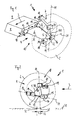
Figur 1- schematisch eine perspektivische Ansicht einer fahrerseitigen Kraftfahrzeughinterradaufhängung eines linken Hinterrades;
Figur 2- schematisch eine Seitenansicht der Kraftfahrzeughinterradaufhängung aus der
Figur 1 Figur 3- schematisch eine Aufsicht der Kraftfahrzeughinterradaufhängung aus
den Figuren 1 und 2 ; und Figur 4- schematisch eine Vorderansicht der Kraftfahrzeughinterradaufhängung aus
den Figuren 1 .bis 3
- FIG. 1
- schematically a perspective view of a driver-side motor vehicle rear suspension of a left rear wheel;
- FIG. 2
- schematically a side view of the motor vehicle rear suspension from the
FIG. 1 ; - FIG. 3
- schematically a plan view of the motor vehicle rear suspension from the
Figures 1 and 2 ; and - FIG. 4
- schematically a front view of the motor vehicle rear suspension from the
FIGS. 1 to 3 ,
Die in den
Feder- und Dämpferelemente sind hierbei der Übersichtlichkeit halber nicht dargestellt, jedoch ebenfalls an der unabhängigen Hinterradaufhängung 1 vorgesehen.Spring and damper elements are not shown here for the sake of clarity, however, also provided on the independent
Die Radführungseinrichtung 4 besteht im Wesentlichen aus einem einzigen unteren Radsteuerarm 6 und einem einzigen oberen Querlenker 7, wobei der einzige untere Radsteuerarm 6 an einem Hilfsrahmen 8 einer Fahrzeugstruktur 9 und der einzige obere Querlenker 7 an einem hier nicht weiter gezeigten weiteren Karosserieteil der Fahrzeugstruktur 9 gelagert ist.The
Vorteilhafter Weise gestalten der einzige untere Radsteuerarm 6 und der einzige obere Querlenker 7 sogleich eine fahrdynamische Radsteuerwinkelverstellung 10 aus, sodass zu deren Realisierung keine weitere Lenkereinrichtung erforderlich ist.Advantageously, the only
Mittels der fahrdynamischen Radsteuerwinkelverstellung 10 kann insbesondere ein vorteilhaftes Eigenlenkverhalten der unabhängigen Hinterradaufhängung 1 bewirkt werden, indem beispielsweise während einer Kurvenfahrt oder eines Bremsvorgangs eine eigendynamische Verstellung des Radsteuerwinkels um eine Radsteuerachse 11 herum erfolgen und damit eine Vorspur 12 verstärkt werden kann (siehe insbesondere
Damit die fahrdynamische Radsteuerwinkelverstellung 10 mit lediglich dem einzigen unteren Radsteuerarm 6 und dem einzigen oberen Querlenker 7 erfolgen kann, sind spezielle Lagerungs- und Lagebedingungen dieser beiden Radführungskomponenten 6 und 7 zu berücksichtigen.Thus, the dynamic driving
Somit umfasst der einzige untere Radsteuerarm 6 ein vorderes inneres Radsteuerarmlager 13, ein vorderes äußeres Radsteuerarmlager 14, ein hinteres inneres Radsteuerarmlager 15 und ein hinteres äußeres Radsteuerarmlager 16.Thus, the single lower
Mittels der beiden inneren Radsteuerarmlager 13 und 15 ist der einzige untere Radsteuerarm 6 an dem Hilfsrahmen 8 gelagert.By means of the two
Mittels der beiden äußeren Radsteuerarmlager 14 und 16 ist der Radnabenträger 5 an dem Radsteuerarm 6 gelagert.By means of the two
Das vordere innere Radsteuerarmlager 13 weist eine Nachgiebigkeit in Längsrichtung 17 auf, die im Wesentlichen mit der Vorwärtsfahrtrichtung 3 fluchtet. Darüber hinaus weist es eine Nachgiebigkeit in lateraler Richtung 18 auf, die im Wesentlichen horizontal quer zur Längsrichtung 17 verläuft. In Vertikalrichtung (der Übersichtlichkeit halber nicht eingezeichnet) ist das Radsteuerarmlager 13 hingegen starr, zumindest relativ gegenüber den Nachgiebigkeiten in Längsrichtung 17 und in lateraler Richtung 18.The front
Das vordere äußere Radsteuerarmlager 14 weist eine Nachgiebigkeit ebenfalls in Längsrichtung 17 auf. Darüber hinaus weist es eine Nachgiebigkeit in lateraler Richtung 18 auf. In Vertikalrichtung ist das vordere äußere Radsteuerarmlager 14 hingegen wieder starr, zumindest relativ gegenüber den Nachgiebigkeiten in Längsrichtung 17 und in lateraler Richtung 18.The front
Das hintere innere Radsteuerarmlager 15 weist im Wesentlichen nur eine Nachgiebigkeit in Längsrichtung 17 auf. In lateraler Richtung 18 und Vertikalrichtung ist es starrer.The rear
Das hintere äußere Radsteuerarmlager 16 weist identische Eigenschaften hinsichtlich seiner Nachgiebigkeit und Starrheit auf wie das hintere innere Radsteuerarmlager 15.The rear
Insofern kann der einzige untere Radsteuerarm 6 im Wesentlichen im hinteren inneren Radsteuerarmlager 15 um eine Hochachse gedreht werden, da insbesondere das vordere innere Radsteuerarmlager 13 eine Nachgiebigkeit in lateraler Richtung 18 besitzt. Dies ist etwa bei einer Kurvenfahrt entscheidend, da hierdurch baulich besonders einfach ein Vorspureffekt begünstigt werden kann. Etwa beim Bremsen ist der einzige untere Radsteuerarm 6 noch translatorisch verschieblich, da beiden inneren Radsteuerarmlagern 13 und 15 eine Nachgiebigkeit in Längsrichtung 17 innewohnt.In this respect, the only
Aufgrund der beschriebenen Lagerbedingungen kann darüber hinaus auch der Radnabenträger 5 im hinteren Radsteuerarmlager 16 gegenüber dem einzigen unteren Radsteuerarm 6 gedreht werden, wodurch der Vorspureffekt nochmals verstärkt werden kann. Hinzu kommt noch eine translatorische Verschieblichkeit des Radnabenträgers 5 gegenüber dem einzigen unteren Radsteuerarm 6 aufgrund der Nachgiebigkeit der beiden äußeren Radsteuerarmlager 14 und 16 in Längsrichtung 17.In addition, due to the described storage conditions, the
Unterseitig ist der Radnabenträger 5 somit vorteilhaft von dem einzigen unteren Radsteuerarm 6 gehalten und geführt.The underside of the
Um den Radnabenträger 5 auch oberseitig vorteilhaft führen zu können, sodass die unabhängige Hinterradaufhängung 1 erfindungsgemäß arbeiten kann, besitzt der einzige obere Querlenker 7 ein inneres Querlenkerlager 19 und ein äußeres Querlenkerlager 20. Beide verfügen nur über eine Nachgiebigkeit in Längsrichtung 17 (hier nur nochmal exemplarisch eingezeichnet), wodurch insbesondere eine erforderliche Bewegungsfreiheit hinsichtlich des äußeren Querlenkerlagers 20 erzielt werden kann, sodass die fahrdynamische Radwinkelverstellung 10 ordnungsgemäß realisiert werden kann. In lateraler Richtung 18 und Vertikalrichtung sind die beiden Querlenkerlager 19, 20 starrer.In order to be able to guide the
Die Radsteuerachse 11 verläuft in diesem Ausführungsbeispiel vorteilhafter Weise direkt durch das äußere Querlenkerlager 20 und einer gedachten Verbindungslinie 21 zwischen den beiden äußeren Radsteuerarmlagern 14 und 16, wobei die Radsteuerachse 11 die Verbindungslinie 21 in einem Schnittpunkt 22 schneidet.The
Dieser Schnittpunkt 22 liegt näher an dem hinteren äußeren Radsteuerarmlager 16 als an dem vorderen äußeren Radsteuerarmlager 14 und damit auch der Verlauf der Radsteuerachse 11.This
Dies kann insbesondere dadurch erzielt werden, indem eine vordere Äquivalentsteifigkeit im vorderen Abschnitt 25 des einzigen unteren Radsteuerarms 6 geringer ist als eine hintere Äquivalentsteifigkeit im hinteren Abschnitt 26 des einzigen unteren Radsteuerarms 6. Hierdurch kann sichergestellt werden, dass ein Radsteuerachsendurchtritt 30 durch einen Untergrund 31, auf welchem das Hinterrad 2 abrollt, stets hinter einem zentrischen Kontaktpunkt 32 des Hinterrades 2 liegt, wodurch sich einerseits ein entsprechend vorteilhafter Nachlaufversatz 33 einstellt und andererseits eine angestrebte Vorspurablenkung möglich ist.This can be achieved in particular by a front equivalent stiffness in the
Idealerweise ist das äußere Querlenkerlager 20 in Vorwärtsfahrtrichtung 3 gesehen hinter der Radnabe 5A des Radnabenträgers 5, aber vor dem äußeren hinteren Radsteuerlager 16 angeordnet.Ideally, the outer wishbone bearing 20 is seen in the
Des Weiteren befindet sich das äußere Querlenkerlager 20 in Vorwärtsfahrtrichtung 3 gesehen vor dem hinteren äußeren Radsteuerarmlager 16, wobei das hintere äußere Radsteuerarmlager 16 hinter der Radnabe 5A des Radnabenträgers 5 platziert ist.Further, the outer
Zudem ist das äußere Querlenkerlager 20 in Vorwärtsfahrtrichtung gesehen vor dem inneren Querlenkerlager 19 angeordnet ist.In addition, the outer wishbone bearing 20 is seen in the forward direction of travel before the inner wishbone bearing 19 is arranged.
Das äußere Querlenkerlager 20 ist in Vorwärtsfahrtrichtung 3 gesehen im Wesentlichen vor dem hinteren äußeren Radsteuerarmlager 16 und das innere Querlenkerlager 19 ist in Vorwärtsfahrtrichtung 3 gesehen im Wesentlichen hinter dem hinteren äußeren Radsteuerarmlager 16 angeordnet.The outer wishbone bearing 20 is seen in the
Darüber hinaus ist vorteilhafter Weise das äußere Querlenkerlager 20 höher angeordnet als das innere Querlenkerlager 19.In addition, advantageously, the outer wishbone bearing 20 is arranged higher than the inner wishbone bearing 19th
Vorteilhafter Weise ist der einzige untere Radsteuerarm 6 in Vorwärtsfahrtrichtung 3 gesehen nach vorne hin ansteigend in der unabhängigen Hinterradaufhängung 1 positioniert (siehe insbesondere
Somit sind in diesem Ausführungsbeispiel auch die beiden vorderen Radsteuerarmlager 13 und 14 höher in der unabhängigen Hinterradaufhängung 1 angeordnet als die beiden hinteren Radsteuerarmlager 15 und 16.Thus, in this embodiment, the two
Wie insbesondere aus der Darstellung nach der
Eine Rotation des Radnabenträgers 5 um die Raddrehachse 40 herum kann vorteilhafter Weise durch die zuvor bereits beschriebene Nachlaufsteifigkeit erzielt werden.A rotation of the
Es versteht sich, dass es sich bei dem vorstehend erläuterten Ausführungsbeispiel lediglich um eine erste Ausgestaltung der erfindungsgemäßen unabhängigen Hinterradaufhängung handelt. Insofern beschränkt sich die Ausgestaltung der Erfindung nicht auf dieses Ausführungsbeispiel.It is understood that the above-described embodiment is only a first embodiment of the independent rear suspension according to the invention. In this respect, the embodiment of the invention is not limited to this embodiment.
Sämtliche in den Anmeldungsunterlagen offenbarten Merkmale werden als erfindungswesentlich beansprucht, sofern sie einzeln oder in Kombination gegenüber dem Stand der Technik neu sind.All disclosed in the application documents features are claimed as essential to the invention, provided they are new individually or in combination over the prior art.
- 11
- unabhängige Hinterradaufhängungindependent rear suspension
- 22
- Hinterradrear wheel
- 33
- VorwärtsfahrtrichtungForward direction
- 44
- RadführungseinrichtungRadführungseinrichtung
- 55
- Radnabenträgerhub carrier
- 5A5A
- Radnabewheel hub
- 66
- einziger unterer Radsteuerarmonly lower wheel control arm
- 77
- einziger oberer Querlenkersingle upper wishbone
- 88th
- Hilfsrahmensubframe
- 99
- Fahrzeugstrukturvehicle structure
- 1010
- RadsteuerwinkelverstellungRadsteuerwinkelverstellung
- 1111
- RadsteuerachseRadsteuerachse
- 1212
- Vorspurtoe
- 1313
- vorderes inneres Radsteuerarmlagerfront inner wheel control arm bearing
- 1414
- vorderes äußeres Radsteuerarmlagerfront outer wheel control arm bearing
- 1515
- hinteres inneres Radsteuerarmlagerrear inner wheel control arm bearing
- 1616
- hinteres äußeres Radsteuerarmlagerrear outer wheel control arm bearing
- 1717
- Längsrichtunglongitudinal direction
- 1818
- laterale Richtunglateral direction
- 1919
- inneres Querlenkerlagerinner wishbone bearing
- 2020
- äußeres Querlenkerlagerouter wishbone bearing
- 2121
- Verbindungslinieconnecting line
- 2222
- Schnittpunktintersection
- 2525
- vorderer Abschnittfront section
- 2626
- hinterer Abschnittrear section
- 3030
- RadsteuerachsendurchtrittRadsteuerachsendurchtritt
- 3131
- Untergrundunderground
- 3232
- Kontaktpunktcontact point
- 3333
- Nachlaufversatztrailing offset
- 4040
- Raddrehachsewheel rotation
- 4141
- Winkelangle
- 4242
- Pfeilrichtungarrow
Claims (8)
Applications Claiming Priority (1)
| Application Number | Priority Date | Filing Date | Title |
|---|---|---|---|
| DE102011086159 | 2011-11-11 |
Publications (2)
| Publication Number | Publication Date |
|---|---|
| EP2591927A1 true EP2591927A1 (en) | 2013-05-15 |
| EP2591927B1 EP2591927B1 (en) | 2015-07-01 |
Family
ID=47226012
Family Applications (1)
| Application Number | Title | Priority Date | Filing Date |
|---|---|---|---|
| EP12192047.4A Active EP2591927B1 (en) | 2011-11-11 | 2012-11-09 | Independent rear wheel suspension of a vehicle |
Country Status (2)
| Country | Link |
|---|---|
| EP (1) | EP2591927B1 (en) |
| DE (1) | DE102012220490A1 (en) |
Cited By (3)
| Publication number | Priority date | Publication date | Assignee | Title |
|---|---|---|---|---|
| WO2020187885A1 (en) * | 2019-03-19 | 2020-09-24 | Jaguar Land Rover Limited | Steering axle assembly |
| CN113543992A (en) * | 2019-03-20 | 2021-10-22 | 奥迪股份公司 | Wheel suspension assembly for a vehicle axle |
| ES2911926A1 (en) * | 2020-11-20 | 2022-05-23 | Azana Perez Samuel | Stabilizer equipment (Machine-translation by Google Translate, not legally binding) |
Citations (13)
| Publication number | Priority date | Publication date | Assignee | Title |
|---|---|---|---|---|
| EP0158279A2 (en) * | 1984-04-10 | 1985-10-16 | Audi Ag | Single-wheel suspension |
| US4772043A (en) * | 1986-04-03 | 1988-09-20 | Toyota Jidosha Kabushiki Kaisha | Suspension for automobile |
| DE19722650A1 (en) * | 1996-05-31 | 1998-01-08 | Toyota Motor Co Ltd | Rear suspension system of motor vehicle |
| EP1288028A2 (en) * | 2001-09-03 | 2003-03-05 | Sistemi Sospensioni S.p.A. | A wheel suspension arm and a motor-vehicle independent suspension system comprising the arm |
| EP1361084A2 (en) * | 2002-05-10 | 2003-11-12 | Sistemi Sospensioni S.p.A. | Mounting structure for a wheel carrier of a motor vehicle |
| EP1422081A2 (en) * | 2002-11-22 | 2004-05-26 | F.Tech Incorporation | Vehicular suspension |
| DE10344733A1 (en) | 2003-09-26 | 2005-10-13 | Audi Ag | Wheel suspension for e.g. passenger car, has two outer swiveling supports connected to two inner swiveling supports that are arranged corresponding to their elasto-kinematic effect so that inner supports support outer supports |
| US20060290091A1 (en) * | 2003-04-22 | 2006-12-28 | Gerrard Miles B | Motor-vehicle independent suspension |
| EP1738938A2 (en) * | 2005-07-01 | 2007-01-03 | Audi Ag | Multi-link independent rear suspension assembly |
| DE102008000982A1 (en) * | 2008-04-03 | 2009-11-05 | Zf Friedrichshafen Ag | vehicle axle |
| US20100102527A1 (en) * | 2007-02-14 | 2010-04-29 | Takuya Yanagida | Suspension device |
| US7823894B2 (en) * | 2004-12-09 | 2010-11-02 | Sistemi Sospensioni S.P.A. | Independent suspension for a motor vehicle |
| DE102010017813A1 (en) * | 2010-07-08 | 2012-01-12 | Ford Global Technologies, Llc. | Suspension arm for wheel suspension, particularly rear wheel suspension for unguided wheels of motor vehicle, has front structure-sided spindle carrier and rear structure-sided spindle carrier |
Family Cites Families (1)
| Publication number | Priority date | Publication date | Assignee | Title |
|---|---|---|---|---|
| ITTO20060246A1 (en) * | 2006-04-03 | 2007-10-04 | Sistemi Sospensioni Spa | ARM FOR AN INDEPENDENT WHEEL SUSPENSION FOR MOTOR VEHICLES AND SUSPENSIONS WITH INDEPENDENT WHEELS FOR MOTOR VEHICLES INCLUDING SUCH ARM |
-
2012
- 2012-11-09 EP EP12192047.4A patent/EP2591927B1/en active Active
- 2012-11-09 DE DE102012220490A patent/DE102012220490A1/en not_active Withdrawn
Patent Citations (13)
| Publication number | Priority date | Publication date | Assignee | Title |
|---|---|---|---|---|
| EP0158279A2 (en) * | 1984-04-10 | 1985-10-16 | Audi Ag | Single-wheel suspension |
| US4772043A (en) * | 1986-04-03 | 1988-09-20 | Toyota Jidosha Kabushiki Kaisha | Suspension for automobile |
| DE19722650A1 (en) * | 1996-05-31 | 1998-01-08 | Toyota Motor Co Ltd | Rear suspension system of motor vehicle |
| EP1288028A2 (en) * | 2001-09-03 | 2003-03-05 | Sistemi Sospensioni S.p.A. | A wheel suspension arm and a motor-vehicle independent suspension system comprising the arm |
| EP1361084A2 (en) * | 2002-05-10 | 2003-11-12 | Sistemi Sospensioni S.p.A. | Mounting structure for a wheel carrier of a motor vehicle |
| EP1422081A2 (en) * | 2002-11-22 | 2004-05-26 | F.Tech Incorporation | Vehicular suspension |
| US20060290091A1 (en) * | 2003-04-22 | 2006-12-28 | Gerrard Miles B | Motor-vehicle independent suspension |
| DE10344733A1 (en) | 2003-09-26 | 2005-10-13 | Audi Ag | Wheel suspension for e.g. passenger car, has two outer swiveling supports connected to two inner swiveling supports that are arranged corresponding to their elasto-kinematic effect so that inner supports support outer supports |
| US7823894B2 (en) * | 2004-12-09 | 2010-11-02 | Sistemi Sospensioni S.P.A. | Independent suspension for a motor vehicle |
| EP1738938A2 (en) * | 2005-07-01 | 2007-01-03 | Audi Ag | Multi-link independent rear suspension assembly |
| US20100102527A1 (en) * | 2007-02-14 | 2010-04-29 | Takuya Yanagida | Suspension device |
| DE102008000982A1 (en) * | 2008-04-03 | 2009-11-05 | Zf Friedrichshafen Ag | vehicle axle |
| DE102010017813A1 (en) * | 2010-07-08 | 2012-01-12 | Ford Global Technologies, Llc. | Suspension arm for wheel suspension, particularly rear wheel suspension for unguided wheels of motor vehicle, has front structure-sided spindle carrier and rear structure-sided spindle carrier |
Cited By (4)
| Publication number | Priority date | Publication date | Assignee | Title |
|---|---|---|---|---|
| WO2020187885A1 (en) * | 2019-03-19 | 2020-09-24 | Jaguar Land Rover Limited | Steering axle assembly |
| CN113543992A (en) * | 2019-03-20 | 2021-10-22 | 奥迪股份公司 | Wheel suspension assembly for a vehicle axle |
| ES2911926A1 (en) * | 2020-11-20 | 2022-05-23 | Azana Perez Samuel | Stabilizer equipment (Machine-translation by Google Translate, not legally binding) |
| WO2022106882A1 (en) * | 2020-11-20 | 2022-05-27 | Azana Perez Samuel | Stabilising device |
Also Published As
| Publication number | Publication date |
|---|---|
| EP2591927B1 (en) | 2015-07-01 |
| DE102012220490A1 (en) | 2013-05-16 |
Similar Documents
| Publication | Publication Date | Title |
|---|---|---|
| EP2282900B1 (en) | Countersteering automotive rear axle | |
| DE3926665C2 (en) | Wheel suspension for motor vehicles | |
| EP3400141B1 (en) | Wheel suspension | |
| DE102010022895A1 (en) | Device for chassis of multilane motor vehicle, has transverse leaf spring that is arranged transverse to vehicle longitudinal axis of motor vehicle, where transverse leaf spring is connected at wheels on one hand of axis | |
| EP3400140B1 (en) | Wheel suspension | |
| DE102013216029A1 (en) | Steerable front axle for wheels of a two-lane motor vehicle and two-lane motor vehicle with such a front axle | |
| EP3672817B1 (en) | Wheel suspension for a motor vehicle | |
| EP2874831B1 (en) | Wheel suspension for the rear axle of a vehicle | |
| EP2591927B1 (en) | Independent rear wheel suspension of a vehicle | |
| DE102017212546A1 (en) | axle assembly | |
| EP3672816A1 (en) | Vehicle axle having a centrally arranged drive unit | |
| DE102006056632A1 (en) | Axle for two-track motor vehicle, has transverse anti-roll bar arranged between wheel suspensions of wheels and supported at supporting point of spring, where point and ends of bar are movable in main effective direction of spring | |
| DE102018207616B4 (en) | Wheel suspension for a motor vehicle | |
| DE3242930A1 (en) | Wheel suspension for motor vehicles | |
| DE102015203906A1 (en) | Semi-active stabilizer arrangement for a chassis of a vehicle | |
| EP3941764B1 (en) | Two-track vehicle with wheel suspension | |
| DE3024845C2 (en) | Steerable damper strut axle for passenger cars | |
| EP3426510A1 (en) | Vehicle torsion beam axle | |
| DE102016122067A1 (en) | WHEEL SUSPENSION FOR A WHEEL OF A VEHICLE | |
| DE102018220235A1 (en) | Independent wheel suspension for a motor vehicle | |
| DE102015009667B4 (en) | Wheel suspension for a vehicle rear axle | |
| DE102019200214A1 (en) | Steerable twist link axle for a motor vehicle, trailing arm and motor vehicle | |
| WO2016116294A1 (en) | Multi-link suspension | |
| DE10016887A1 (en) | Individual wheel suspension; has wheel support coupled to side frame by suspension arrangement, where side frame is supported elastokinematically at vehicle chassis at at least three points | |
| DE4339856C2 (en) | Wheel suspension, in particular for the rear wheels of motor vehicles |
Legal Events
| Date | Code | Title | Description |
|---|---|---|---|
| PUAI | Public reference made under article 153(3) epc to a published international application that has entered the european phase |
Free format text: ORIGINAL CODE: 0009012 |
|
| AK | Designated contracting states |
Kind code of ref document: A1 Designated state(s): AL AT BE BG CH CY CZ DE DK EE ES FI FR GB GR HR HU IE IS IT LI LT LU LV MC MK MT NL NO PL PT RO RS SE SI SK SM TR |
|
| AX | Request for extension of the european patent |
Extension state: BA ME |
|
| 17P | Request for examination filed |
Effective date: 20130930 |
|
| RBV | Designated contracting states (corrected) |
Designated state(s): AL AT BE BG CH CY CZ DE DK EE ES FI FR GB GR HR HU IE IS IT LI LT LU LV MC MK MT NL NO PL PT RO RS SE SI SK SM TR |
|
| 17Q | First examination report despatched |
Effective date: 20140808 |
|
| GRAJ | Information related to disapproval of communication of intention to grant by the applicant or resumption of examination proceedings by the epo deleted |
Free format text: ORIGINAL CODE: EPIDOSDIGR1 |
|
| GRAP | Despatch of communication of intention to grant a patent |
Free format text: ORIGINAL CODE: EPIDOSNIGR1 |
|
| INTG | Intention to grant announced |
Effective date: 20150306 |
|
| INTG | Intention to grant announced |
Effective date: 20150316 |
|
| GRAS | Grant fee paid |
Free format text: ORIGINAL CODE: EPIDOSNIGR3 |
|
| GRAA | (expected) grant |
Free format text: ORIGINAL CODE: 0009210 |
|
| AK | Designated contracting states |
Kind code of ref document: B1 Designated state(s): AL AT BE BG CH CY CZ DE DK EE ES FI FR GB GR HR HU IE IS IT LI LT LU LV MC MK MT NL NO PL PT RO RS SE SI SK SM TR |
|
| REG | Reference to a national code |
Ref country code: GB Ref legal event code: FG4D Free format text: NOT ENGLISH |
|
| REG | Reference to a national code |
Ref country code: AT Ref legal event code: REF Ref document number: 733721 Country of ref document: AT Kind code of ref document: T Effective date: 20150715 Ref country code: CH Ref legal event code: EP |
|
| REG | Reference to a national code |
Ref country code: IE Ref legal event code: FG4D Free format text: LANGUAGE OF EP DOCUMENT: GERMAN |
|
| REG | Reference to a national code |
Ref country code: DE Ref legal event code: R096 Ref document number: 502012003595 Country of ref document: DE |
|
| REG | Reference to a national code |
Ref country code: FR Ref legal event code: PLFP Year of fee payment: 4 |
|
| REG | Reference to a national code |
Ref country code: NL Ref legal event code: MP Effective date: 20150701 |
|
| REG | Reference to a national code |
Ref country code: LT Ref legal event code: MG4D |
|
| PG25 | Lapsed in a contracting state [announced via postgrant information from national office to epo] |
Ref country code: LT Free format text: LAPSE BECAUSE OF FAILURE TO SUBMIT A TRANSLATION OF THE DESCRIPTION OR TO PAY THE FEE WITHIN THE PRESCRIBED TIME-LIMIT Effective date: 20150701 Ref country code: LV Free format text: LAPSE BECAUSE OF FAILURE TO SUBMIT A TRANSLATION OF THE DESCRIPTION OR TO PAY THE FEE WITHIN THE PRESCRIBED TIME-LIMIT Effective date: 20150701 Ref country code: GR Free format text: LAPSE BECAUSE OF FAILURE TO SUBMIT A TRANSLATION OF THE DESCRIPTION OR TO PAY THE FEE WITHIN THE PRESCRIBED TIME-LIMIT Effective date: 20151002 Ref country code: FI Free format text: LAPSE BECAUSE OF FAILURE TO SUBMIT A TRANSLATION OF THE DESCRIPTION OR TO PAY THE FEE WITHIN THE PRESCRIBED TIME-LIMIT Effective date: 20150701 Ref country code: NO Free format text: LAPSE BECAUSE OF FAILURE TO SUBMIT A TRANSLATION OF THE DESCRIPTION OR TO PAY THE FEE WITHIN THE PRESCRIBED TIME-LIMIT Effective date: 20151001 |
|
| PG25 | Lapsed in a contracting state [announced via postgrant information from national office to epo] |
Ref country code: HR Free format text: LAPSE BECAUSE OF FAILURE TO SUBMIT A TRANSLATION OF THE DESCRIPTION OR TO PAY THE FEE WITHIN THE PRESCRIBED TIME-LIMIT Effective date: 20150701 Ref country code: SE Free format text: LAPSE BECAUSE OF FAILURE TO SUBMIT A TRANSLATION OF THE DESCRIPTION OR TO PAY THE FEE WITHIN THE PRESCRIBED TIME-LIMIT Effective date: 20150701 Ref country code: PT Free format text: LAPSE BECAUSE OF FAILURE TO SUBMIT A TRANSLATION OF THE DESCRIPTION OR TO PAY THE FEE WITHIN THE PRESCRIBED TIME-LIMIT Effective date: 20151102 Ref country code: ES Free format text: LAPSE BECAUSE OF FAILURE TO SUBMIT A TRANSLATION OF THE DESCRIPTION OR TO PAY THE FEE WITHIN THE PRESCRIBED TIME-LIMIT Effective date: 20150701 Ref country code: PL Free format text: LAPSE BECAUSE OF FAILURE TO SUBMIT A TRANSLATION OF THE DESCRIPTION OR TO PAY THE FEE WITHIN THE PRESCRIBED TIME-LIMIT Effective date: 20150701 Ref country code: IS Free format text: LAPSE BECAUSE OF FAILURE TO SUBMIT A TRANSLATION OF THE DESCRIPTION OR TO PAY THE FEE WITHIN THE PRESCRIBED TIME-LIMIT Effective date: 20151101 Ref country code: RS Free format text: LAPSE BECAUSE OF FAILURE TO SUBMIT A TRANSLATION OF THE DESCRIPTION OR TO PAY THE FEE WITHIN THE PRESCRIBED TIME-LIMIT Effective date: 20150701 |
|
| REG | Reference to a national code |
Ref country code: DE Ref legal event code: R097 Ref document number: 502012003595 Country of ref document: DE |
|
| PG25 | Lapsed in a contracting state [announced via postgrant information from national office to epo] |
Ref country code: CZ Free format text: LAPSE BECAUSE OF FAILURE TO SUBMIT A TRANSLATION OF THE DESCRIPTION OR TO PAY THE FEE WITHIN THE PRESCRIBED TIME-LIMIT Effective date: 20150701 Ref country code: IT Free format text: LAPSE BECAUSE OF FAILURE TO SUBMIT A TRANSLATION OF THE DESCRIPTION OR TO PAY THE FEE WITHIN THE PRESCRIBED TIME-LIMIT Effective date: 20150701 Ref country code: SK Free format text: LAPSE BECAUSE OF FAILURE TO SUBMIT A TRANSLATION OF THE DESCRIPTION OR TO PAY THE FEE WITHIN THE PRESCRIBED TIME-LIMIT Effective date: 20150701 Ref country code: EE Free format text: LAPSE BECAUSE OF FAILURE TO SUBMIT A TRANSLATION OF THE DESCRIPTION OR TO PAY THE FEE WITHIN THE PRESCRIBED TIME-LIMIT Effective date: 20150701 Ref country code: DK Free format text: LAPSE BECAUSE OF FAILURE TO SUBMIT A TRANSLATION OF THE DESCRIPTION OR TO PAY THE FEE WITHIN THE PRESCRIBED TIME-LIMIT Effective date: 20150701 |
|
| PLBE | No opposition filed within time limit |
Free format text: ORIGINAL CODE: 0009261 |
|
| STAA | Information on the status of an ep patent application or granted ep patent |
Free format text: STATUS: NO OPPOSITION FILED WITHIN TIME LIMIT |
|
| PG25 | Lapsed in a contracting state [announced via postgrant information from national office to epo] |
Ref country code: RO Free format text: LAPSE BECAUSE OF FAILURE TO SUBMIT A TRANSLATION OF THE DESCRIPTION OR TO PAY THE FEE WITHIN THE PRESCRIBED TIME-LIMIT Effective date: 20150701 |
|
| 26N | No opposition filed |
Effective date: 20160404 |
|
| PG25 | Lapsed in a contracting state [announced via postgrant information from national office to epo] |
Ref country code: LU Free format text: LAPSE BECAUSE OF FAILURE TO SUBMIT A TRANSLATION OF THE DESCRIPTION OR TO PAY THE FEE WITHIN THE PRESCRIBED TIME-LIMIT Effective date: 20151109 Ref country code: MC Free format text: LAPSE BECAUSE OF FAILURE TO SUBMIT A TRANSLATION OF THE DESCRIPTION OR TO PAY THE FEE WITHIN THE PRESCRIBED TIME-LIMIT Effective date: 20150701 |
|
| REG | Reference to a national code |
Ref country code: CH Ref legal event code: PL |
|
| PG25 | Lapsed in a contracting state [announced via postgrant information from national office to epo] |
Ref country code: LI Free format text: LAPSE BECAUSE OF NON-PAYMENT OF DUE FEES Effective date: 20151130 Ref country code: CH Free format text: LAPSE BECAUSE OF NON-PAYMENT OF DUE FEES Effective date: 20151130 |
|
| REG | Reference to a national code |
Ref country code: IE Ref legal event code: MM4A |
|
| PG25 | Lapsed in a contracting state [announced via postgrant information from national office to epo] |
Ref country code: SI Free format text: LAPSE BECAUSE OF FAILURE TO SUBMIT A TRANSLATION OF THE DESCRIPTION OR TO PAY THE FEE WITHIN THE PRESCRIBED TIME-LIMIT Effective date: 20150701 |
|
| REG | Reference to a national code |
Ref country code: FR Ref legal event code: PLFP Year of fee payment: 5 |
|
| PG25 | Lapsed in a contracting state [announced via postgrant information from national office to epo] |
Ref country code: IE Free format text: LAPSE BECAUSE OF NON-PAYMENT OF DUE FEES Effective date: 20151109 |
|
| PG25 | Lapsed in a contracting state [announced via postgrant information from national office to epo] |
Ref country code: SM Free format text: LAPSE BECAUSE OF FAILURE TO SUBMIT A TRANSLATION OF THE DESCRIPTION OR TO PAY THE FEE WITHIN THE PRESCRIBED TIME-LIMIT Effective date: 20150701 Ref country code: HU Free format text: LAPSE BECAUSE OF FAILURE TO SUBMIT A TRANSLATION OF THE DESCRIPTION OR TO PAY THE FEE WITHIN THE PRESCRIBED TIME-LIMIT; INVALID AB INITIO Effective date: 20121109 Ref country code: BG Free format text: LAPSE BECAUSE OF FAILURE TO SUBMIT A TRANSLATION OF THE DESCRIPTION OR TO PAY THE FEE WITHIN THE PRESCRIBED TIME-LIMIT Effective date: 20150701 |
|
| PG25 | Lapsed in a contracting state [announced via postgrant information from national office to epo] |
Ref country code: NL Free format text: LAPSE BECAUSE OF FAILURE TO SUBMIT A TRANSLATION OF THE DESCRIPTION OR TO PAY THE FEE WITHIN THE PRESCRIBED TIME-LIMIT Effective date: 20150701 Ref country code: CY Free format text: LAPSE BECAUSE OF FAILURE TO SUBMIT A TRANSLATION OF THE DESCRIPTION OR TO PAY THE FEE WITHIN THE PRESCRIBED TIME-LIMIT Effective date: 20150701 |
|
| PG25 | Lapsed in a contracting state [announced via postgrant information from national office to epo] |
Ref country code: BE Free format text: LAPSE BECAUSE OF NON-PAYMENT OF DUE FEES Effective date: 20151130 |
|
| PG25 | Lapsed in a contracting state [announced via postgrant information from national office to epo] |
Ref country code: MT Free format text: LAPSE BECAUSE OF FAILURE TO SUBMIT A TRANSLATION OF THE DESCRIPTION OR TO PAY THE FEE WITHIN THE PRESCRIBED TIME-LIMIT Effective date: 20150701 |
|
| REG | Reference to a national code |
Ref country code: FR Ref legal event code: PLFP Year of fee payment: 6 |
|
| PG25 | Lapsed in a contracting state [announced via postgrant information from national office to epo] |
Ref country code: TR Free format text: LAPSE BECAUSE OF FAILURE TO SUBMIT A TRANSLATION OF THE DESCRIPTION OR TO PAY THE FEE WITHIN THE PRESCRIBED TIME-LIMIT Effective date: 20150701 Ref country code: MK Free format text: LAPSE BECAUSE OF FAILURE TO SUBMIT A TRANSLATION OF THE DESCRIPTION OR TO PAY THE FEE WITHIN THE PRESCRIBED TIME-LIMIT Effective date: 20150701 |
|
| REG | Reference to a national code |
Ref country code: FR Ref legal event code: PLFP Year of fee payment: 7 |
|
| PG25 | Lapsed in a contracting state [announced via postgrant information from national office to epo] |
Ref country code: AL Free format text: LAPSE BECAUSE OF FAILURE TO SUBMIT A TRANSLATION OF THE DESCRIPTION OR TO PAY THE FEE WITHIN THE PRESCRIBED TIME-LIMIT Effective date: 20150701 |
|
| REG | Reference to a national code |
Ref country code: AT Ref legal event code: MM01 Ref document number: 733721 Country of ref document: AT Kind code of ref document: T Effective date: 20171109 |
|
| PG25 | Lapsed in a contracting state [announced via postgrant information from national office to epo] |
Ref country code: AT Free format text: LAPSE BECAUSE OF NON-PAYMENT OF DUE FEES Effective date: 20171109 |
|
| PGFP | Annual fee paid to national office [announced via postgrant information from national office to epo] |
Ref country code: FR Payment date: 20191029 Year of fee payment: 8 |
|
| PGFP | Annual fee paid to national office [announced via postgrant information from national office to epo] |
Ref country code: GB Payment date: 20191029 Year of fee payment: 8 |
|
| GBPC | Gb: european patent ceased through non-payment of renewal fee |
Effective date: 20201109 |
|
| PG25 | Lapsed in a contracting state [announced via postgrant information from national office to epo] |
Ref country code: FR Free format text: LAPSE BECAUSE OF NON-PAYMENT OF DUE FEES Effective date: 20201130 |
|
| PG25 | Lapsed in a contracting state [announced via postgrant information from national office to epo] |
Ref country code: GB Free format text: LAPSE BECAUSE OF NON-PAYMENT OF DUE FEES Effective date: 20201109 |
|
| P01 | Opt-out of the competence of the unified patent court (upc) registered |
Effective date: 20230620 |
|
| PGFP | Annual fee paid to national office [announced via postgrant information from national office to epo] |
Ref country code: DE Payment date: 20231010 Year of fee payment: 12 |