EP2591660A1 - Machine de récolte en particulier pour plantes sarclées - Google Patents
Machine de récolte en particulier pour plantes sarclées Download PDFInfo
- Publication number
- EP2591660A1 EP2591660A1 EP12007632.8A EP12007632A EP2591660A1 EP 2591660 A1 EP2591660 A1 EP 2591660A1 EP 12007632 A EP12007632 A EP 12007632A EP 2591660 A1 EP2591660 A1 EP 2591660A1
- Authority
- EP
- European Patent Office
- Prior art keywords
- machine according
- harvesting machine
- control
- region
- actuating cylinder
- Prior art date
- Legal status (The legal status is an assumption and is not a legal conclusion. Google has not performed a legal analysis and makes no representation as to the accuracy of the status listed.)
- Granted
Links
- 238000003306 harvesting Methods 0.000 claims abstract description 30
- 230000033001 locomotion Effects 0.000 claims abstract description 14
- 230000005284 excitation Effects 0.000 claims description 17
- 235000002595 Solanum tuberosum Nutrition 0.000 claims description 8
- 244000061456 Solanum tuberosum Species 0.000 claims description 8
- 238000013016 damping Methods 0.000 claims description 4
- 235000016068 Berberis vulgaris Nutrition 0.000 claims description 3
- 241000335053 Beta vulgaris Species 0.000 claims description 3
- 230000008859 change Effects 0.000 claims description 3
- 235000012015 potatoes Nutrition 0.000 claims description 3
- 230000001953 sensory effect Effects 0.000 claims description 3
- 230000002123 temporal effect Effects 0.000 claims description 2
- 238000012544 monitoring process Methods 0.000 description 5
- 230000010355 oscillation Effects 0.000 description 4
- 239000006096 absorbing agent Substances 0.000 description 2
- 230000001133 acceleration Effects 0.000 description 2
- 230000000712 assembly Effects 0.000 description 2
- 238000000429 assembly Methods 0.000 description 2
- 238000010276 construction Methods 0.000 description 2
- 238000013461 design Methods 0.000 description 2
- 238000001514 detection method Methods 0.000 description 2
- 238000010586 diagram Methods 0.000 description 2
- 238000005259 measurement Methods 0.000 description 2
- 238000000034 method Methods 0.000 description 2
- 230000008569 process Effects 0.000 description 2
- 239000002689 soil Substances 0.000 description 2
- 235000011293 Brassica napus Nutrition 0.000 description 1
- 240000008100 Brassica rapa Species 0.000 description 1
- 235000000540 Brassica rapa subsp rapa Nutrition 0.000 description 1
- 241001124569 Lycaenidae Species 0.000 description 1
- 230000004913 activation Effects 0.000 description 1
- 238000001994 activation Methods 0.000 description 1
- 230000002411 adverse Effects 0.000 description 1
- 238000011161 development Methods 0.000 description 1
- 230000018109 developmental process Effects 0.000 description 1
- 238000006073 displacement reaction Methods 0.000 description 1
- 230000009977 dual effect Effects 0.000 description 1
- 230000000694 effects Effects 0.000 description 1
- 230000008029 eradication Effects 0.000 description 1
- 230000001747 exhibiting effect Effects 0.000 description 1
- 239000012530 fluid Substances 0.000 description 1
- 230000005484 gravity Effects 0.000 description 1
- 230000003993 interaction Effects 0.000 description 1
- 238000012545 processing Methods 0.000 description 1
- 239000000725 suspension Substances 0.000 description 1
- 230000007704 transition Effects 0.000 description 1
Images


Classifications
-
- A—HUMAN NECESSITIES
- A01—AGRICULTURE; FORESTRY; ANIMAL HUSBANDRY; HUNTING; TRAPPING; FISHING
- A01D—HARVESTING; MOWING
- A01D33/00—Accessories for digging harvesters
-
- A—HUMAN NECESSITIES
- A01—AGRICULTURE; FORESTRY; ANIMAL HUSBANDRY; HUNTING; TRAPPING; FISHING
- A01D—HARVESTING; MOWING
- A01D75/00—Accessories for harvesters or mowers
- A01D75/28—Control mechanisms for harvesters or mowers when moving on slopes; Devices preventing lateral pull
Definitions
- the invention relates to a harvester for root crops such as potatoes, beets o. The like. Crop according to the preamble of claim 1.
- the invention addresses the problem of creating a harvester in the form of a potato or beet harvester, in which the driving speed can be maintained even when driving over uneven soil structures and with little technical effort adverse effects on the picking and collection process of the crop is largely excluded ,
- Superstructures having harvester is inventively improved by the fact that in the area of the machine frame, in particular acting transversely to the direction machine movement, namely, inclinations, fluctuations, oscillations o. The like., Detecting and this actively counteracting control device is provided. The movements are sensory detected, and by means of a signal processing controller, an actuator is then controlled so that the intended optimal working conditions are maintained in the field of the structures of the harvester.
- the harvesting machine can already be improved by having an actuating cylinder having at least one pressure sensor in the region between the machine frame and a support shaft receiving the support wheels and this cooperates with a hydraulic or electrical control.
- This ensures that recorded by driving excitations via the support wheels in the machine system recorded vibrations and can be actively influenced.
- the actuating cylinder, the pressure sensor and the control thereby form a surprisingly effective functional unit on a harvester, so that driving excitations and vibrations initiated on uneven running areas can be compensated for and / or are automatically reduced to a limit value by means of a counter-force or a counter-torque.
- a monitoring unit in which the actuating cylinder provided with pressure sensors can be used as an active vibration damper.
- a tilt adjusting cylinder which is already present in the known machine concepts, is adapted and this is thus used "twice”.
- the effective as a vibration absorber actuator cylinder is integrated as an additional module in the system of the harvester.
- an acceleration sensor instead of the pressure sensor provided as a sensor of the component movements and / or deformations, an acceleration sensor, a force meter or the like may also be provided.
- the oil volume flow can be influenced by means of a continuous valve designed in particular as an electromagnetic proportional valve. It is also conceivable that the actuating cylinder is connected via a computerized control and programs with a Regventil or a servo valve. It is provided that respective analogue signals of the at least one pressure sensor are processed in a control unit and thereafter the proportional valve is digitally controlled by means of its output signal.
- the controllable or controllable system provides that advantageously two pressure sensors are installed in the area of the adjusting cylinder.
- the two pressure sensors are each arranged on a piston side or a ring side of the actuating cylinder, so that by means of the actuating cylinder both pressure and tensile forces (as a result of driving excitations) can be detected.
- a permissible limit value is then defined for these driving excitations, so that when it is reached a corresponding counter-control can be initiated by means of the actuating cylinder acting as a vibration absorber.
- a vibration amplitude derivable from the measurement signals of the pressure sensors is provided as the excitation limit value.
- a respective desired value for the control of the proportional valve can be specified.
- This proportional valve is used efficiently, because not only discrete switching positions can be used, but by a steady transition of the respective valve openings and linearly variable flow rates are possible.
- the control concept can also be designed so that a respective time sequence of pressure fluctuations in the area of the adjusting cylinder is detected as the limit value, and from this the respective desired value for corresponding valve activations is predefined by means of the control program.
- the concept according to the invention provides that in the area of the programmable control the respective output signal of the inclination sensor can be efficiently linked to the output signals of the two pressure sensors.
- a shift of the actuation times in the area of the proportional valve is simultaneously possible.
- inclination change of the harvester so that a targeted shift of the respective target value for the excitation limit value of the actuating cylinder can be performed and thus the machine control can be adapted to an optimal harvesting process even on uneven terrain.
- the above-described, largely automated control concept for the above-described harvester is provided with a software or a control program, whereby the known automatic tilt can be largely integrated into the means of at least one actuating cylinder activatable vibration damping and thus a particularly efficient operating concept is achieved.
- the above-described monitoring and automatic eradication of vibrations resulting from the driving excitation in the area of a harvesting machine can also be improved by providing a plurality of actuating cylinders connected to the hydraulic control by sensors and the control program in the area of the machine frame.
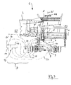
- Fig. 1 is a total of 1 designated harvester for root crops such as potatoes, turnips o. Like. Crop E shown. This drawn by a tractor (not shown) embodiment of the harvester 1 has a respective harvest and Siebaggregate 2, a collection bunker 3 u. Like. Abstructions supporting machine frame 4. In the rear area of this machine frame, at least two support wheels 6, 7 connected to a support shaft 5 are provided for the bottom support ( Fig. 2 ).
- the inventively improved concept of the harvester 1 provides that between the machine frame 4 and the support shaft 5 in the vicinity of at least one of the support wheels 6, 7 ( Fig. 2 ) is provided in the region of pressure lines at least one pressure sensor A, B exhibiting actuating cylinder 8.
- the actuating cylinder 8 is on the one hand connected to the support shaft 5 formed as axle tube 9 by means of a flange 10, and on the other hand engages the actuating cylinder 8 in the region of a chassis part 11 on the machine frame 4.
- This has an upper main frame 4 ', which is to be moved during the use of the machine 1 with the smallest possible displacements with respect to a horizontal plane H, so that tilting about the center of gravity S and the vertical vertical axis H' are avoided.
- adjusting components in the form of a so-called "tilting cylinder” are already known, which are provided with likewise known inclination sensors N (FIG. Fig. 3 ) can work together.
- the actuating cylinder 8 provided according to the invention in the new operative context is designed such that respective driving excitations (arrow C) transmitted by the support wheels 6, 7 into the region of the machine structure 4, 4 ' Fig. 2 ) detectable and by means of the control cylinder 8 associated control D (schematic diagram, Fig. 3 ) are actively influenced.
- respective driving excitations (arrow C) transmitted by the support wheels 6, 7 into the region of the machine structure 4, 4 ' Fig. 2 ) detectable and by means of the control cylinder 8 associated control D (schematic diagram, Fig. 3 ) are actively influenced.
- Fig. 2 and Fig. 3 As from the synopsis of Fig. 2 and Fig. 3 it can be seen, is adapted in effective implementation of the concept of existing already in the machine 1 inclination adjusting cylinder so that the actuating cylinder 8 shown now has a "dual function".
- the constructive design in the area of the adjusting cylinder 8 provides that a continuous valve designed in particular as an electromagnetic proportional valve 12 is provided for controlling the oil volume flow emanating from a hydraulic motor M (for example in the region of the tractor), which via the two sensors A, B with a digital Control unit 13 in the form of a microprocessor, a computer o. The like. ( Fig. 3 ) cooperates. This ensures that the respective analog signals of the pressure sensors A, B in particular via electrical connection lines 17, 18 are transmitted to the control unit 13 and then via an internal control program 14, the proportional valve 11 via lines 19, 20 are controlled.
- the preferred embodiment of the multifunctional actuating cylinder 8 provides that this is provided with two pressure sensors A, B, which are respectively effective on a piston side and a ring side of the actuating cylinder 8. This ensures that by means of the actuating cylinder 8 both pressure and tensile forces from the region of the support wheel 6 (arrow C) can be detected and transmitted via the lines 17, 18 to the control unit 14. From the combination of the above-described assemblies it is clear that by means of the sensors A, B of the actuating cylinder or (s) 8 respective driving excitations in the form of oscillating movements (arrow C) in the area of the superstructures of the machine 1 can be detected and for each of these driving excitations resulting vibrations ( Fig.
- a machine-typical permissible limit can be defined.
- the proportional valve 12 is activated so that the detected vibrations are counteracted and a "rocking" of the machine 1 or its components (filling bunker 3) is avoided.
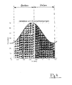
- An oscillation amplitude derivable from the measurement signals of the pressure sensors A, B is advantageous ( Fig. 4 , Curve 21) provided as an excitation limit, such that by means of the controller 14, a respective desired value for the control of the electromagnetic proportional valve 12 can be predetermined. It is also conceivable that a respective temporal sequence of pressure fluctuations ( Fig. 4 , Axis Z) is detected and derived from the respective setpoint for valve controls.
- the control in the region of the valve 12 and the actuating cylinder 8 is adjusted so that, for example, with increasing pressure (“bump" with stroke at C) in the range of the actuating cylinder 8 a "evasive movement" by lowering the fluid pressure on a piston side is possible. Thus, a "rocking" of the system can be avoided.
- Fig. 3 it can be seen that in the area of the machine frame 4, 4 ', an additional tilt sensor N is installed. Its output signal is combined by means of a line 22 in the region of the programmable controller 14 with the output signals 17, 18 of the pressure sensors A, B. Efficient programming in the area of the control 14 ensures that upon detection of a deviation from a predefinable desired inclination position (plane H, Fig. 2 ) by means of the controller 14, the drive times ( Fig. 4 , Z axis) in the region of the proportional valve 12 to be moved or changed. In this case, the program can also be set so that when a change in inclination of the harvester 1 of the respective target value for the excitation limit ( Fig.
- the above-described harvester 1 has in the region of the machine frame 4, 4 'only one adjusting cylinder 8, wherein it is also conceivable to integrate several associated with the hydraulic control D by sensors and the control program actuating cylinder in the system. Likewise, it is conceivable to integrate as sensors and acceleration sensors, deformation or force meter o. The like. Converter in the system and thus to further optimize the above-described control or regulation processes.
Applications Claiming Priority (1)
| Application Number | Priority Date | Filing Date | Title |
|---|---|---|---|
| DE201110118205 DE102011118205A1 (de) | 2011-11-11 | 2011-11-11 | Erntemaschine für insbesondere Hackfrüchte |
Publications (2)
| Publication Number | Publication Date |
|---|---|
| EP2591660A1 true EP2591660A1 (fr) | 2013-05-15 |
| EP2591660B1 EP2591660B1 (fr) | 2015-11-25 |
Family
ID=47221073
Family Applications (1)
| Application Number | Title | Priority Date | Filing Date |
|---|---|---|---|
| EP12007632.8A Active EP2591660B1 (fr) | 2011-11-11 | 2012-11-09 | Machine de récolte en particulier pour plantes sarclées |
Country Status (2)
| Country | Link |
|---|---|
| EP (1) | EP2591660B1 (fr) |
| DE (1) | DE102011118205A1 (fr) |
Cited By (4)
| Publication number | Priority date | Publication date | Assignee | Title |
|---|---|---|---|---|
| EP2910097A1 (fr) * | 2014-02-19 | 2015-08-26 | Deere & Company | Dispositif de commande amortissant les vibrations d'un actionneur d'une machine de travail agricole |
| EP3210447A1 (fr) * | 2016-02-25 | 2017-08-30 | Deere & Company | Détermination autonome de paramètres de réglage d'un système de commande d'un actionneur de déplacement d'un élément mobile d'une machine de travail agricole |
| BE1024691B1 (nl) * | 2016-10-24 | 2018-05-29 | Dewulf Nv | Rooimachine |
| US10588258B2 (en) | 2016-02-25 | 2020-03-17 | Deere & Company | Automatic determination of the control unit parameters of an arrangement to control an actuator for the adjustment of an adjustable element of an agricultural machine |
Citations (7)
| Publication number | Priority date | Publication date | Assignee | Title |
|---|---|---|---|---|
| GB1039659A (en) * | 1962-08-02 | 1966-08-17 | Mather & Platt Ltd | Improvements in or relating to viners |
| FR1569021A (fr) * | 1967-03-28 | 1969-05-30 | ||
| GB1189705A (en) * | 1967-08-03 | 1970-04-29 | Automotive Prod Co Ltd | Improvements in or relating to Levelling Devices for Mobile Structures. |
| DE9320575U1 (de) | 1993-08-19 | 1994-09-15 | Grimme Landmaschf Franz | Kartoffelvollerntemaschine |
| DE9320576U1 (de) | 1993-08-31 | 1994-09-15 | Grimme Landmaschf Franz | Kartoffelerntemaschine |
| EP1880591A1 (fr) | 2006-07-22 | 2008-01-23 | Grimme Landmaschinenfabrik GmbH & Co. KG | Machine de récolte de pommes de terre |
| DE102007034446A1 (de) | 2007-07-20 | 2009-01-22 | Grimme Landmaschinenfabrik Gmbh & Co. Kg | Kartoffelerntemaschine |
Family Cites Families (1)
| Publication number | Priority date | Publication date | Assignee | Title |
|---|---|---|---|---|
| DE10345822A1 (de) * | 2003-09-30 | 2005-04-14 | Claas Selbstfahrende Erntemaschinen Gmbh | Verfahren zur Bodenkopierung für Vorsatzgeräte |
-
2011
- 2011-11-11 DE DE201110118205 patent/DE102011118205A1/de not_active Withdrawn
-
2012
- 2012-11-09 EP EP12007632.8A patent/EP2591660B1/fr active Active
Patent Citations (7)
| Publication number | Priority date | Publication date | Assignee | Title |
|---|---|---|---|---|
| GB1039659A (en) * | 1962-08-02 | 1966-08-17 | Mather & Platt Ltd | Improvements in or relating to viners |
| FR1569021A (fr) * | 1967-03-28 | 1969-05-30 | ||
| GB1189705A (en) * | 1967-08-03 | 1970-04-29 | Automotive Prod Co Ltd | Improvements in or relating to Levelling Devices for Mobile Structures. |
| DE9320575U1 (de) | 1993-08-19 | 1994-09-15 | Grimme Landmaschf Franz | Kartoffelvollerntemaschine |
| DE9320576U1 (de) | 1993-08-31 | 1994-09-15 | Grimme Landmaschf Franz | Kartoffelerntemaschine |
| EP1880591A1 (fr) | 2006-07-22 | 2008-01-23 | Grimme Landmaschinenfabrik GmbH & Co. KG | Machine de récolte de pommes de terre |
| DE102007034446A1 (de) | 2007-07-20 | 2009-01-22 | Grimme Landmaschinenfabrik Gmbh & Co. Kg | Kartoffelerntemaschine |
Cited By (5)
| Publication number | Priority date | Publication date | Assignee | Title |
|---|---|---|---|---|
| EP2910097A1 (fr) * | 2014-02-19 | 2015-08-26 | Deere & Company | Dispositif de commande amortissant les vibrations d'un actionneur d'une machine de travail agricole |
| US9832926B2 (en) | 2014-02-19 | 2017-12-05 | Deere & Company | Vibration-damping triggering of an actuator for an agricultural working machine |
| EP3210447A1 (fr) * | 2016-02-25 | 2017-08-30 | Deere & Company | Détermination autonome de paramètres de réglage d'un système de commande d'un actionneur de déplacement d'un élément mobile d'une machine de travail agricole |
| US10588258B2 (en) | 2016-02-25 | 2020-03-17 | Deere & Company | Automatic determination of the control unit parameters of an arrangement to control an actuator for the adjustment of an adjustable element of an agricultural machine |
| BE1024691B1 (nl) * | 2016-10-24 | 2018-05-29 | Dewulf Nv | Rooimachine |
Also Published As
| Publication number | Publication date |
|---|---|
| EP2591660B1 (fr) | 2015-11-25 |
| DE102011118205A1 (de) | 2013-05-16 |
Similar Documents
| Publication | Publication Date | Title |
|---|---|---|
| EP2910097B1 (fr) | Dispositif de commande amortissant les vibrations d'un actionneur d'une machine de travail agricole | |
| EP3072379B1 (fr) | Amortissement du tangage d'un vehicule de travail par modification de la vitesse | |
| EP3357333B1 (fr) | Machine d'épandage agricole à commande automatique d'amortissement de la r ampe d'épandage | |
| DE4130877C2 (fr) | ||
| EP3250030B1 (fr) | Machine agricole | |
| EP2591660B1 (fr) | Machine de récolte en particulier pour plantes sarclées | |
| DE102014019168A1 (de) | BAUMASCHINE, INSBESONDERE STRAßENFRÄSE, UND VERFAHREN ZUM AUSGLEICHEN VON BODENUNEBENHEITEN FÜR EINE SOLCHE BAUMASCHINE | |
| EP2047736B1 (fr) | Plieuse pour pommes de terre | |
| EP2939518A1 (fr) | Système de vérification prenant en compte la dynamique de véhicule destiné au réglage de position d'un appareil pour un véhicule de travail agricole | |
| DE202011111069U1 (de) | Landwirtschaftliches Fahrzeug zum Sprühen | |
| DE102005040174A1 (de) | Landwirtschaftliche Presse | |
| EP3634124B1 (fr) | Tringlerie de distributeur | |
| EP2982243B1 (fr) | Dispositif et procede de commande de mouvement d'une rampe d'un dispositif d'epandage agricole | |
| EP2248690A2 (fr) | Châssis pour véhicules spéciaux | |
| DE102020203524A1 (de) | Dämpfung von Nickschwingungen eines Arbeitsfahrzeugs durch Geschwindigkeitsänderung und Verstellung eines Elements unter Berücksichtigung der Betriebsart | |
| WO2020135921A1 (fr) | Engin de chantier, en particulier engin de fraisage de chaussées, ainsi que procédé pour commander la position de levage d'une unité piston-cylindre d'une colonne de levage d'un engin de chantier | |
| EP3718400B1 (fr) | Machine d'épandage agricole doté d'une rampe d'épandage | |
| DE102015104690A1 (de) | Landwirtschaftliche Maschine und Sicherheitsverfahren | |
| EP3165090A1 (fr) | Système de commande et/ou de réglage d'une machine agricole | |
| DE102014117904A1 (de) | Bodengebundenes Fahrzeug mit einer Einrichtung zur Verringerung der Bodenverdichtung | |
| EP3791707A1 (fr) | Dispositif de traitement au sol de matériau végétal et procédé de traitement au sol de matériau végétal | |
| EP3061332A1 (fr) | Unite d'entrainement a portique pour un vehicule agricole reglable en hauteur | |
| EP3300598A1 (fr) | Procédé et dispositif de pulvérisation permettant la distribution d'un fluide de pulvérisation sur une superficie agricole | |
| EP0566033B1 (fr) | Cadre support pour machine de récolte, en particulier faucheuse rotative | |
| EP3210447B1 (fr) | Détermination autonome de paramètres de réglage d'un système de commande d'un actionneur de déplacement d'un élément mobile d'une machine de travail agricole |
Legal Events
| Date | Code | Title | Description |
|---|---|---|---|
| PUAI | Public reference made under article 153(3) epc to a published international application that has entered the european phase |
Free format text: ORIGINAL CODE: 0009012 |
|
| AK | Designated contracting states |
Kind code of ref document: A1 Designated state(s): AL AT BE BG CH CY CZ DE DK EE ES FI FR GB GR HR HU IE IS IT LI LT LU LV MC MK MT NL NO PL PT RO RS SE SI SK SM TR |
|
| AX | Request for extension of the european patent |
Extension state: BA ME |
|
| 17P | Request for examination filed |
Effective date: 20130618 |
|
| RBV | Designated contracting states (corrected) |
Designated state(s): AL AT BE BG CH CY CZ DE DK EE ES FI FR GB GR HR HU IE IS IT LI LT LU LV MC MK MT NL NO PL PT RO RS SE SI SK SM TR |
|
| GRAP | Despatch of communication of intention to grant a patent |
Free format text: ORIGINAL CODE: EPIDOSNIGR1 |
|
| GRAS | Grant fee paid |
Free format text: ORIGINAL CODE: EPIDOSNIGR3 |
|
| INTG | Intention to grant announced |
Effective date: 20150617 |
|
| GRAA | (expected) grant |
Free format text: ORIGINAL CODE: 0009210 |
|
| AK | Designated contracting states |
Kind code of ref document: B1 Designated state(s): AL AT BE BG CH CY CZ DE DK EE ES FI FR GB GR HR HU IE IS IT LI LT LU LV MC MK MT NL NO PL PT RO RS SE SI SK SM TR |
|
| REG | Reference to a national code |
Ref country code: GB Ref legal event code: FG4D Free format text: NOT ENGLISH |
|
| REG | Reference to a national code |
Ref country code: CH Ref legal event code: EP |
|
| REG | Reference to a national code |
Ref country code: AT Ref legal event code: REF Ref document number: 762120 Country of ref document: AT Kind code of ref document: T Effective date: 20151215 |
|
| REG | Reference to a national code |
Ref country code: IE Ref legal event code: FG4D Free format text: LANGUAGE OF EP DOCUMENT: GERMAN |
|
| REG | Reference to a national code |
Ref country code: DE Ref legal event code: R096 Ref document number: 502012005315 Country of ref document: DE |
|
| REG | Reference to a national code |
Ref country code: NL Ref legal event code: FP |
|
| REG | Reference to a national code |
Ref country code: LT Ref legal event code: MG4D |
|
| PG25 | Lapsed in a contracting state [announced via postgrant information from national office to epo] |
Ref country code: IS Free format text: LAPSE BECAUSE OF FAILURE TO SUBMIT A TRANSLATION OF THE DESCRIPTION OR TO PAY THE FEE WITHIN THE PRESCRIBED TIME-LIMIT Effective date: 20160325 Ref country code: NO Free format text: LAPSE BECAUSE OF FAILURE TO SUBMIT A TRANSLATION OF THE DESCRIPTION OR TO PAY THE FEE WITHIN THE PRESCRIBED TIME-LIMIT Effective date: 20160225 Ref country code: HR Free format text: LAPSE BECAUSE OF FAILURE TO SUBMIT A TRANSLATION OF THE DESCRIPTION OR TO PAY THE FEE WITHIN THE PRESCRIBED TIME-LIMIT Effective date: 20151125 Ref country code: ES Free format text: LAPSE BECAUSE OF FAILURE TO SUBMIT A TRANSLATION OF THE DESCRIPTION OR TO PAY THE FEE WITHIN THE PRESCRIBED TIME-LIMIT Effective date: 20151125 Ref country code: LT Free format text: LAPSE BECAUSE OF FAILURE TO SUBMIT A TRANSLATION OF THE DESCRIPTION OR TO PAY THE FEE WITHIN THE PRESCRIBED TIME-LIMIT Effective date: 20151125 |
|
| PG25 | Lapsed in a contracting state [announced via postgrant information from national office to epo] |
Ref country code: RS Free format text: LAPSE BECAUSE OF FAILURE TO SUBMIT A TRANSLATION OF THE DESCRIPTION OR TO PAY THE FEE WITHIN THE PRESCRIBED TIME-LIMIT Effective date: 20151125 Ref country code: GR Free format text: LAPSE BECAUSE OF FAILURE TO SUBMIT A TRANSLATION OF THE DESCRIPTION OR TO PAY THE FEE WITHIN THE PRESCRIBED TIME-LIMIT Effective date: 20160226 Ref country code: PL Free format text: LAPSE BECAUSE OF FAILURE TO SUBMIT A TRANSLATION OF THE DESCRIPTION OR TO PAY THE FEE WITHIN THE PRESCRIBED TIME-LIMIT Effective date: 20151125 Ref country code: FI Free format text: LAPSE BECAUSE OF FAILURE TO SUBMIT A TRANSLATION OF THE DESCRIPTION OR TO PAY THE FEE WITHIN THE PRESCRIBED TIME-LIMIT Effective date: 20151125 Ref country code: SE Free format text: LAPSE BECAUSE OF FAILURE TO SUBMIT A TRANSLATION OF THE DESCRIPTION OR TO PAY THE FEE WITHIN THE PRESCRIBED TIME-LIMIT Effective date: 20151125 Ref country code: PT Free format text: LAPSE BECAUSE OF FAILURE TO SUBMIT A TRANSLATION OF THE DESCRIPTION OR TO PAY THE FEE WITHIN THE PRESCRIBED TIME-LIMIT Effective date: 20160325 Ref country code: LV Free format text: LAPSE BECAUSE OF FAILURE TO SUBMIT A TRANSLATION OF THE DESCRIPTION OR TO PAY THE FEE WITHIN THE PRESCRIBED TIME-LIMIT Effective date: 20151125 |
|
| PG25 | Lapsed in a contracting state [announced via postgrant information from national office to epo] |
Ref country code: CZ Free format text: LAPSE BECAUSE OF FAILURE TO SUBMIT A TRANSLATION OF THE DESCRIPTION OR TO PAY THE FEE WITHIN THE PRESCRIBED TIME-LIMIT Effective date: 20151125 Ref country code: IT Free format text: LAPSE BECAUSE OF FAILURE TO SUBMIT A TRANSLATION OF THE DESCRIPTION OR TO PAY THE FEE WITHIN THE PRESCRIBED TIME-LIMIT Effective date: 20151125 |
|
| REG | Reference to a national code |
Ref country code: DE Ref legal event code: R097 Ref document number: 502012005315 Country of ref document: DE |
|
| PG25 | Lapsed in a contracting state [announced via postgrant information from national office to epo] |
Ref country code: SM Free format text: LAPSE BECAUSE OF FAILURE TO SUBMIT A TRANSLATION OF THE DESCRIPTION OR TO PAY THE FEE WITHIN THE PRESCRIBED TIME-LIMIT Effective date: 20151125 Ref country code: DK Free format text: LAPSE BECAUSE OF FAILURE TO SUBMIT A TRANSLATION OF THE DESCRIPTION OR TO PAY THE FEE WITHIN THE PRESCRIBED TIME-LIMIT Effective date: 20151125 Ref country code: RO Free format text: LAPSE BECAUSE OF FAILURE TO SUBMIT A TRANSLATION OF THE DESCRIPTION OR TO PAY THE FEE WITHIN THE PRESCRIBED TIME-LIMIT Effective date: 20151125 Ref country code: EE Free format text: LAPSE BECAUSE OF FAILURE TO SUBMIT A TRANSLATION OF THE DESCRIPTION OR TO PAY THE FEE WITHIN THE PRESCRIBED TIME-LIMIT Effective date: 20151125 Ref country code: SK Free format text: LAPSE BECAUSE OF FAILURE TO SUBMIT A TRANSLATION OF THE DESCRIPTION OR TO PAY THE FEE WITHIN THE PRESCRIBED TIME-LIMIT Effective date: 20151125 |
|
| PLBE | No opposition filed within time limit |
Free format text: ORIGINAL CODE: 0009261 |
|
| STAA | Information on the status of an ep patent application or granted ep patent |
Free format text: STATUS: NO OPPOSITION FILED WITHIN TIME LIMIT |
|
| 26N | No opposition filed |
Effective date: 20160826 |
|
| REG | Reference to a national code |
Ref country code: FR Ref legal event code: PLFP Year of fee payment: 5 |
|
| PG25 | Lapsed in a contracting state [announced via postgrant information from national office to epo] |
Ref country code: SI Free format text: LAPSE BECAUSE OF FAILURE TO SUBMIT A TRANSLATION OF THE DESCRIPTION OR TO PAY THE FEE WITHIN THE PRESCRIBED TIME-LIMIT Effective date: 20151125 |
|
| REG | Reference to a national code |
Ref country code: CH Ref legal event code: PL |
|
| GBPC | Gb: european patent ceased through non-payment of renewal fee |
Effective date: 20161109 |
|
| PG25 | Lapsed in a contracting state [announced via postgrant information from national office to epo] |
Ref country code: LI Free format text: LAPSE BECAUSE OF NON-PAYMENT OF DUE FEES Effective date: 20161130 Ref country code: CH Free format text: LAPSE BECAUSE OF NON-PAYMENT OF DUE FEES Effective date: 20161130 |
|
| REG | Reference to a national code |
Ref country code: IE Ref legal event code: MM4A |
|
| PG25 | Lapsed in a contracting state [announced via postgrant information from national office to epo] |
Ref country code: LU Free format text: LAPSE BECAUSE OF NON-PAYMENT OF DUE FEES Effective date: 20161130 |
|
| REG | Reference to a national code |
Ref country code: FR Ref legal event code: PLFP Year of fee payment: 6 |
|
| PG25 | Lapsed in a contracting state [announced via postgrant information from national office to epo] |
Ref country code: IE Free format text: LAPSE BECAUSE OF NON-PAYMENT OF DUE FEES Effective date: 20161109 Ref country code: GB Free format text: LAPSE BECAUSE OF NON-PAYMENT OF DUE FEES Effective date: 20161109 |
|
| PG25 | Lapsed in a contracting state [announced via postgrant information from national office to epo] |
Ref country code: CY Free format text: LAPSE BECAUSE OF FAILURE TO SUBMIT A TRANSLATION OF THE DESCRIPTION OR TO PAY THE FEE WITHIN THE PRESCRIBED TIME-LIMIT Effective date: 20151125 Ref country code: HU Free format text: LAPSE BECAUSE OF FAILURE TO SUBMIT A TRANSLATION OF THE DESCRIPTION OR TO PAY THE FEE WITHIN THE PRESCRIBED TIME-LIMIT; INVALID AB INITIO Effective date: 20121109 |
|
| PG25 | Lapsed in a contracting state [announced via postgrant information from national office to epo] |
Ref country code: TR Free format text: LAPSE BECAUSE OF FAILURE TO SUBMIT A TRANSLATION OF THE DESCRIPTION OR TO PAY THE FEE WITHIN THE PRESCRIBED TIME-LIMIT Effective date: 20151125 Ref country code: MK Free format text: LAPSE BECAUSE OF FAILURE TO SUBMIT A TRANSLATION OF THE DESCRIPTION OR TO PAY THE FEE WITHIN THE PRESCRIBED TIME-LIMIT Effective date: 20151125 Ref country code: MC Free format text: LAPSE BECAUSE OF FAILURE TO SUBMIT A TRANSLATION OF THE DESCRIPTION OR TO PAY THE FEE WITHIN THE PRESCRIBED TIME-LIMIT Effective date: 20151125 |
|
| PG25 | Lapsed in a contracting state [announced via postgrant information from national office to epo] |
Ref country code: BG Free format text: LAPSE BECAUSE OF FAILURE TO SUBMIT A TRANSLATION OF THE DESCRIPTION OR TO PAY THE FEE WITHIN THE PRESCRIBED TIME-LIMIT Effective date: 20151125 |
|
| PG25 | Lapsed in a contracting state [announced via postgrant information from national office to epo] |
Ref country code: MT Free format text: LAPSE BECAUSE OF FAILURE TO SUBMIT A TRANSLATION OF THE DESCRIPTION OR TO PAY THE FEE WITHIN THE PRESCRIBED TIME-LIMIT Effective date: 20151125 |
|
| PG25 | Lapsed in a contracting state [announced via postgrant information from national office to epo] |
Ref country code: AL Free format text: LAPSE BECAUSE OF FAILURE TO SUBMIT A TRANSLATION OF THE DESCRIPTION OR TO PAY THE FEE WITHIN THE PRESCRIBED TIME-LIMIT Effective date: 20151125 |
|
| REG | Reference to a national code |
Ref country code: AT Ref legal event code: MM01 Ref document number: 762120 Country of ref document: AT Kind code of ref document: T Effective date: 20171109 |
|
| PG25 | Lapsed in a contracting state [announced via postgrant information from national office to epo] |
Ref country code: AT Free format text: LAPSE BECAUSE OF NON-PAYMENT OF DUE FEES Effective date: 20171109 |
|
| PGFP | Annual fee paid to national office [announced via postgrant information from national office to epo] |
Ref country code: NL Payment date: 20231122 Year of fee payment: 12 |
|
| PGFP | Annual fee paid to national office [announced via postgrant information from national office to epo] |
Ref country code: FR Payment date: 20231122 Year of fee payment: 12 Ref country code: DE Payment date: 20231120 Year of fee payment: 12 |
|
| PGFP | Annual fee paid to national office [announced via postgrant information from national office to epo] |
Ref country code: BE Payment date: 20231121 Year of fee payment: 12 |