EP2591271B1 - Versiegelungsvorrichtung zum verbinden von zwei rohren - Google Patents
Versiegelungsvorrichtung zum verbinden von zwei rohren Download PDFInfo
- Publication number
- EP2591271B1 EP2591271B1 EP10754553.5A EP10754553A EP2591271B1 EP 2591271 B1 EP2591271 B1 EP 2591271B1 EP 10754553 A EP10754553 A EP 10754553A EP 2591271 B1 EP2591271 B1 EP 2591271B1
- Authority
- EP
- European Patent Office
- Prior art keywords
- sealing
- pipe
- members
- sealing device
- sealing members
- Prior art date
- Legal status (The legal status is an assumption and is not a legal conclusion. Google has not performed a legal analysis and makes no representation as to the accuracy of the status listed.)
- Not-in-force
Links
- 238000007789 sealing Methods 0.000 title claims description 316
- 239000012530 fluid Substances 0.000 claims description 17
- 238000006073 displacement reaction Methods 0.000 claims description 12
- 239000007788 liquid Substances 0.000 claims description 3
- 229910000831 Steel Inorganic materials 0.000 description 4
- 239000010959 steel Substances 0.000 description 4
- 238000004519 manufacturing process Methods 0.000 description 2
- 230000006978 adaptation Effects 0.000 description 1
- 239000003822 epoxy resin Substances 0.000 description 1
- 239000000463 material Substances 0.000 description 1
- 229920000647 polyepoxide Polymers 0.000 description 1
- 238000003825 pressing Methods 0.000 description 1
- 229920005989 resin Polymers 0.000 description 1
- 239000011347 resin Substances 0.000 description 1
- 230000000717 retained effect Effects 0.000 description 1
- 230000000630 rising effect Effects 0.000 description 1
- 230000035939 shock Effects 0.000 description 1
- XLYOFNOQVPJJNP-UHFFFAOYSA-N water Substances O XLYOFNOQVPJJNP-UHFFFAOYSA-N 0.000 description 1
Images

Classifications
-
- F—MECHANICAL ENGINEERING; LIGHTING; HEATING; WEAPONS; BLASTING
- F16—ENGINEERING ELEMENTS AND UNITS; GENERAL MEASURES FOR PRODUCING AND MAINTAINING EFFECTIVE FUNCTIONING OF MACHINES OR INSTALLATIONS; THERMAL INSULATION IN GENERAL
- F16L—PIPES; JOINTS OR FITTINGS FOR PIPES; SUPPORTS FOR PIPES, CABLES OR PROTECTIVE TUBING; MEANS FOR THERMAL INSULATION IN GENERAL
- F16L55/00—Devices or appurtenances for use in, or in connection with, pipes or pipe systems
- F16L55/10—Means for stopping flow in pipes or hoses
- F16L55/1018—Pivoting closing devices
-
- E—FIXED CONSTRUCTIONS
- E21—EARTH OR ROCK DRILLING; MINING
- E21B—EARTH OR ROCK DRILLING; OBTAINING OIL, GAS, WATER, SOLUBLE OR MELTABLE MATERIALS OR A SLURRY OF MINERALS FROM WELLS
- E21B43/00—Methods or apparatus for obtaining oil, gas, water, soluble or meltable materials or a slurry of minerals from wells
- E21B43/01—Methods or apparatus for obtaining oil, gas, water, soluble or meltable materials or a slurry of minerals from wells specially adapted for obtaining from underwater installations
- E21B43/0122—Collecting oil or the like from a submerged leakage
-
- F—MECHANICAL ENGINEERING; LIGHTING; HEATING; WEAPONS; BLASTING
- F16—ENGINEERING ELEMENTS AND UNITS; GENERAL MEASURES FOR PRODUCING AND MAINTAINING EFFECTIVE FUNCTIONING OF MACHINES OR INSTALLATIONS; THERMAL INSULATION IN GENERAL
- F16L—PIPES; JOINTS OR FITTINGS FOR PIPES; SUPPORTS FOR PIPES, CABLES OR PROTECTIVE TUBING; MEANS FOR THERMAL INSULATION IN GENERAL
- F16L1/00—Laying or reclaiming pipes; Repairing or joining pipes on or under water
- F16L1/26—Repairing or joining pipes on or under water
-
- F—MECHANICAL ENGINEERING; LIGHTING; HEATING; WEAPONS; BLASTING
- F16—ENGINEERING ELEMENTS AND UNITS; GENERAL MEASURES FOR PRODUCING AND MAINTAINING EFFECTIVE FUNCTIONING OF MACHINES OR INSTALLATIONS; THERMAL INSULATION IN GENERAL
- F16L—PIPES; JOINTS OR FITTINGS FOR PIPES; SUPPORTS FOR PIPES, CABLES OR PROTECTIVE TUBING; MEANS FOR THERMAL INSULATION IN GENERAL
- F16L55/00—Devices or appurtenances for use in, or in connection with, pipes or pipe systems
- F16L55/10—Means for stopping flow in pipes or hoses
- F16L55/1022—Fluid cut-off devices automatically actuated
-
- F—MECHANICAL ENGINEERING; LIGHTING; HEATING; WEAPONS; BLASTING
- F16—ENGINEERING ELEMENTS AND UNITS; GENERAL MEASURES FOR PRODUCING AND MAINTAINING EFFECTIVE FUNCTIONING OF MACHINES OR INSTALLATIONS; THERMAL INSULATION IN GENERAL
- F16L—PIPES; JOINTS OR FITTINGS FOR PIPES; SUPPORTS FOR PIPES, CABLES OR PROTECTIVE TUBING; MEANS FOR THERMAL INSULATION IN GENERAL
- F16L55/00—Devices or appurtenances for use in, or in connection with, pipes or pipe systems
- F16L55/16—Devices for covering leaks in pipes or hoses, e.g. hose-menders
- F16L55/162—Devices for covering leaks in pipes or hoses, e.g. hose-menders from inside the pipe
- F16L55/165—Devices for covering leaks in pipes or hoses, e.g. hose-menders from inside the pipe a pipe or flexible liner being inserted in the damaged section
- F16L55/1657—Devices for covering leaks in pipes or hoses, e.g. hose-menders from inside the pipe a pipe or flexible liner being inserted in the damaged section lengths of rigid pipe being inserted
-
- F—MECHANICAL ENGINEERING; LIGHTING; HEATING; WEAPONS; BLASTING
- F16—ENGINEERING ELEMENTS AND UNITS; GENERAL MEASURES FOR PRODUCING AND MAINTAINING EFFECTIVE FUNCTIONING OF MACHINES OR INSTALLATIONS; THERMAL INSULATION IN GENERAL
- F16L—PIPES; JOINTS OR FITTINGS FOR PIPES; SUPPORTS FOR PIPES, CABLES OR PROTECTIVE TUBING; MEANS FOR THERMAL INSULATION IN GENERAL
- F16L55/00—Devices or appurtenances for use in, or in connection with, pipes or pipe systems
- F16L55/18—Appliances for use in repairing pipes
Definitions
- the invention relates to a sealing device for making at least partially fluid-tight a connection between a first pipe having a predetermined inside diameter and a second pipe having an outside diameter smaller than said inside diameter of the first pipe, a part of the second pipe extending in a longitudinal direction and being able to be engaged in the first pipe while leaving an inter-pipes space between the two pipes in the radial direction, the sealing device being mounted on a supporting pipe which is one of the first and second pipes and being adapted to spread out in said inter-pipes space from a guard position to a sealing position.
- Such type of sealing device is found for example in US4648626A which describes a telescopic joint for underwater pipelines, comprising an inner pipe provided with an expandable steel sheath.
- a gap is created between the steel sheath and an inner cylinder forming an end part of the inner pipe, and is connected to pressure means so that applying pressure in the gap causes the steel sheath to deform and to expand in order to interlock with an outer pipe.
- the fluid injected in the gap can be an epoxy resin which solidifies to obtain a permanently deformed sheath.
- injecting a resin under pressure may be difficult, especially in underwater conditions where water pressure is high.
- the deformation ability of the steel sheath is not high, therefore the outer diameter of the sheath before expansion cannot be significantly lower than the inner diameter of the outer pipe and consequently the radial length of the inter-pipes space is necessarily small.
- the device is disadvantageous in a configuration in which the inner pipe has to be introduced and guided into the outer pipe and the guidance conditions are difficult, for instance in case of an alignment shift between the outer pipe and a telescopic inner pipe when introducing the inner pipe.
- the invention provides a sealing device of the kind in question comprising at least one sealing set including substantially rigid movable sealing members which extend each along a predetermined angular sector in a circumferential direction and are individually guided in displacement between said guard position and said sealing position.
- the sealing device By means of these dispositions, a relatively large spread out amplitude of the sealing device between the guard position and the sealing position can be obtained, compared to the prior art device of US4648626A .
- at least one sealing member may be impeded to spread out without impeding the other sealing members to reach their sealing positions. This allows to substantially seal an inter-pipes space in which a remaining element stays which hinders a complete spread out of one sealing member, and to obtain an incomplete sealing which can be however acceptable if most of the inter-pipes space cross section is covered by the sealing members of a sealing set. For instance, if the remaining element is a drill pipe which remains inside a broken leaking pipeline, the sealing device may be mounted on a pipe to be introduced inside the leaking end of the pipeline and may seal up to about 95% of the leak in the sealing position.
- the sealing device comprises one or more of the following dispositions:
- the invention also provides a telescopic connection module comprising an enclosure and a telescopic tube in communication with an inner space of the enclosure, the telescopic tube being movable in translation between a rearward position and a forward position and comprising a front portion provided with a sealing device according to the invention.
- a telescopic connection module for instance an underwater transportable module, is provided with a telescopic tube able to be connected to a stationary pipe, for instance an underwater broken and leaking pipeline, in order to canalize the leaking oil into the module and to collect the oil via an output pipe connected to the module.
- the telescopic connection module comprises one or more of the following dispositions:
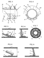
- a first embodiment of a telescopic connection module 3 comprising a sealing device 5 according to the invention is brought to be positioned in front of an open end of a first pipe 1 lying on the ocean floor, typically an accidently broken pipe carrying oil which flows out through the open end.
- the connection module 3 comprises an enclosure 4 and a telescopic tube forming a second pipe 2 in communication with an inner space of the enclosure.
- the telescopic tube 2 is movable in translation along a longitudinal direction A between a rearward position and a forward position, and is represented in its forward position in which it is introduced inside the first pipe 1.
- the telescopic tube 2 is able to slide along a tubular guide 18 secured to the enclosure 4 in a fluid-tight manner, and is operated by an actuation mechanism 8 provided with pivoting rods 8A and 8B ( FIG.2 ).
- the pivoting rod 8B consists in a toggle lever able to lock the forward position of the tube 2.
- the toggle lever 8B is in rotation abutment in said forward position of the tube 2, so that a rearward effort exerted on the tube 2 and applied to the pivoting rod 8A tends to maintain the toggle lever 8B in abutment.
- a positioning guiding arm 7 is hinged to the enclosure 4 and adapted to come in contact with the pipe 1 to position the connection module 3 relatively to the pipe 1, so that the telescopic tube 2 is substantially in alignment with the pipe 1.
- a front portion of the telescopic tube 2 is provided with a sealing device 5 which comprises two sealing sets 10 and 11 substantially identical and spaced one another in the longitudinal direction, each sealing set including substantially rigid movable sealing members 12 ( FIGS. 2 and 3 ).
- the second pipe 2 forms a supporting pipe for the sealing device 5.
- Each sealing member 12 extends along a predetermined angular sector in a circumferential direction and is individually guided in displacement between a guard position and a sealing position.
- the first pipe 1 may include at least one smaller pipe, for instance a drill pipe 9 remaining in a bottom part of the pipe 1.
- the sealing device 5 is dimensioned to have an outer diameter in the guard position small enough so that the drill pipe 9 does not impede the device 5 to be introduced in the pipe 1.
- a front end portion 2E of the telescopic tube 2 can have a larger diameter than the above mentioned outer diameter and can be tapered, to facilitate introduction of the tube 2 while protecting the sealing device 5 in the guard position from radial shocks against the pipe 1.
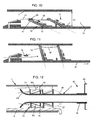
- the front tapered end portion 2E of the telescopic supporting pipe 2 may comprise fluid passages 2H directing a fluid flow towards sealing members 12 of a front sealing set 10, so that the fluid pressure exerted on a sealing member 12 in the guard position by a fluid flow is able to pivot the sealing member to reach the sealing position when the sealing sets 10 and 11 are released.
- the sealing sets 10 and 11 each comprise sealing members 12 which overlap each other and leave inter-blade spaces G between themselves through which the fluid coming from the pipe 1 can pass. In this manner, some fluid passes through the front sealing set 10 so that a fluid pressure is also exerted on the rear sealing set 11, which may serve to spread out the latter.
- the sealing members 12 are viewed both in a guard position and in a sealing position. More precisely, the top half parts of the drawings show the sealing sets 10 and 11 in the sealing position in which several or all sealing members 12 extend in a plane which is perpendicular to a longitudinal axis A of the supporting pipe 2.
- the sealing members have side edges 12S extending in a radial direction and which are in contact with each other in a fluid-tight manner.
- the length of a side edge 12S is equal to or slightly greater than the radial length of the inter-pipe space D1 between the two pipes 1 and 2.
- a distal edge 12E of a sealing member 12 is arc shaped with a radius sensibly equal to an inner radius of the first pipe 1.
- the bottom half parts of the drawings show the sealing sets 10 and 11 in the guard position in which the sealing members 12 are pivoted about individual axis mounted on base members 17 which are secured to the supporting pipe 2.
- the outer diameter of a sealing set is minimized in the guard position.
- the sealing members 12 are sliding sealing members each mounted sliding along a first pivoting arm 13 according to a predetermined travel L2.
- a first pivoting arm 13 is adapted to pivot on a corresponding base member 17, in a plane which contains the longitudinal axis A of the supporting pipe 2, and comprises an oblong hole 13H which is traversed by a sliding pin 16 secured to the corresponding sealing member 12.
- a sealing member 12 slides along the corresponding first pivoting arm 13 between the guard position and the sealing position, to allow a proximal edge of the sealing member to come in sealing contact with the supporting pipe 2 in the sealing position.
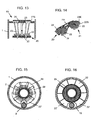
- the sealing device 5 can be adapted so that only one sealing member 12 of a sealing set 10 or 11 is substantially impeded by the drill pipe 9 to pivot.
- the angular sector of a sealing member 12 in the circumferential direction can be predetermined so that a non-sealed area 19 around the drill pipe 9 is relatively small and acceptable in view of the sealed area of the inter-pipe space.
- the telescopic connection module 3 may comprise an angular positioning system to rotate the telescopic supporting pipe 2 about its longitudinal axis A in order to angularly position the sealing device relative to the drill pipe 9.
- it may be provided a gap in the circumferential direction between two consecutive sealing members of a sealing set 10 or 11, so that the drill pipe 9 fits into this gap when the sealing set is spread out with all sealing members being pivoted.
- each sealing set 10 and 11 includes an alternation of sliding sealing members and of non-sliding sealing members.
- the sliding sealing members of a sealing set can be like those represented in FIGS. 10 and 11 , and can have substantially the same length L1 as the non-sliding sealing members. They can be positioned for instance shifted forward relative to the non-sliding sealing members of the set.
- the number of sliding sealing members can be about the same as the number of non-sliding sealing members, which lowers the manufacturing costs since the non-sliding sealing members are easier to produce due to their simpler structure.
- sealing members 12 When the sealing members 12 have a length L1 which is greater than a radial length D1 of said the inter-pipes space, they form an generally tapered arrangement.
- a distal edge 12E of a sealing member 12 can be elliptically shaped in order to be in sealing contact with the inner surface of the first pipe 1.
- Most or all sealing members 12 can overlap each other in a significantly fluid-tight manner, somewhat like the tiles of a roof. This configuration is advantageous to avoid breaking the sealing device in the sealing position if some lateral efforts tend to incline one pipe relative to the other, because the sealing members can pivotally retract to reduce the strains applied on them.
- the ability of the sealing members to retract also facilitates withdrawal of the second pipe 2 from the first pipe 1 if disassembling of the pipe connection is needed.
- both front and rear sealing sets 10 and 11 include an alternation of sliding sealing members able to slide on their pivoting support arms and of non-sliding sealing members.
- the non-sliding sealing members are not represented in the drawings, for sake of conciseness.
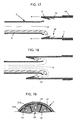
- Two retaining rings 35 may be used respectively for the sliding sealing members and the non-sliding sealing members of a same sealing set, in order to sequentially release the two kinds of sealing members and to decrease mutual friction between their overlapping edges when the sealing sets spread out.
- Each sealing member of the rear sealing set is not strictly parallel to the corresponding front sealing member and is linked to the latter through a link cable 32 extending sensibly in a longitudinal direction, so that the rear set is retained by the front set.
- Each link cable 32 is arranged so as to be slack in the sealing position represented in FIG. 11 , to allow possible deviations of parallelism between the front and rear sealing members which ensures that a rear sealing member is applied with a sufficient pressure of contact against the inner surface of the pipe 1.
- the retaining device further comprises at least one retaining cable 31 passing by pulleys, connected to the enclosure and able to be actuated to pull forward the retaining ring 35 so as to release the ring and to allow the sealing members 12 to be displaced in the sealing position, as represented in FIG. 11 .
- Two retaining cables 31 arranged diametraly on the telescopic second pipe 2 can be preferred to efficiently pull forward the retaining ring.
- two retaining rings with retaining cables extending rearwards could be provided respectively for the front and rear sealing sets.
- the retaining rings could be therefore easily re-positioned by a robot if the second pipe 2 and the sealing device represented in FIG. 11 have to be withdrawn from the first pipe 1 to be used again in another first pipe.
- a second embodiment of a telescopic connection module comprises a sealing device 15 according to a second embodiment of the invention.
- the connection module 30 can be also disposed on the sea floor, and is connected to a broken pipe 1 carrying oil.
- the sealing device 15 includes sealing members 22 which are mounted to slide on guidance ramps 23 secured to the supporting telescopic pipe 2.
- a guidance ramp 23 is dedicated to a single sealing member 22 and is arranged so that the sealing member moves away from the supporting pipe 2 when it is displaced towards its sealing position.
- the sealing device 15 comprises two sets of respectively front and rear sealing members 22.
- Two longitudinally aligned sealing members 22 are rigidly linked to each other through a linking bar 22L so as to form a movable pair of sealing members which spread out simultaneously when rising along the respective guidance ramps 23. Therefore, the two sealing sets spread out simultaneously.
- the guidance ramps 23 of a sealing set are distributed in a circumferential direction and form a conical arrangement which bears on an annular sealing wall 25.
- a front tapered end of the telescopic pipe 2 comprises apertures 2H adapted so that a flow of oil passing through said apertures exerts the needed pressure on the front sealing set, in order to displace the two sealing sets when a retaining device which can be analogue to the one of the first embodiment is released.
- each pair of linked front and rear sealing members can be connected to a reel 26 through a cable 27 attached to the rear sealing member.
- the reel 26 exerts on the cable 27 a pulling force adapted to pull rearwards said pair of sealing members at least on a part of the displacement path to the sealing position which is represented in dash line.
- the sealing members 22 of a front sealing set 20 are alternatively shifted in the longitudinal direction so that they overlap each other in the guard position, whereas they are adapted to be arranged in a same plane in the sealing position so as to be in sealing contact with the annular sealing wall 25.
- a plane arrangement in the sealing position is not necessary. A satisfactory sealing may be obtained also with overlapping sealing members, even though an adaptation of the annular sealing wall 25 would be needed.
- the sealing members of a rear sealing set 21 are alternatively shifted in the same manner.
- each sealing member 22 is provided with a guiding base member 24 adapted to cooperate in a sliding manner with a corresponding guidance ramp 23.
- a distal edge 22E of a sealing member 22 is arc shaped with a radius equal to an inner radius of the first pipe 1.
- the sealing members have side edges 22S extending in a radial direction.
- a sealing set 20 or 21 may comprise two sealing members 22' which have shapes being different from the shape of the sealing members 22, in order to provide a better sealing at the vicinity of a drill pipe 9 remaining in the first pipe 1.
- Each sealing member 22' has a concave side cut adapted so as to decrease the non-sealed area 19 around the drill pipe 9 in the sealing position, as represented in FIG. 16 .
- a telescopic connection module may comprise a sealing device according to a third embodiment of the invention.
- the sealing device is mounted on the inside surface of a supporting telescopic pipe 1 which has an inner diameter larger than an outer diameter of a broken pipe 2 to be sealed.
- the sealing device comprises a sealing set 10' formed with pivoting sealing members 12' similar to the sealing members 12 in the first embodiment of the invention.
- the sealing members 12' are each mounted to slide along a dedicated pivoting arm 13' according to a predetermined travel, a pivoting arm 13' being adapted to pivot in a plan which contains a longitudinal axis of the telescopic pipe 1.
- the pivoting arms 13' are mounted on supports 17' which are secured to the inside surface of the supporting pipe 1, and have rotation axis which are coplanar in a plane perpendicular to said longitudinal axis.
- a part of the sealing members 12' can be mounted secured to dedicated second pivoting arms and overlap with adjacent sliding sealing members 12' in the sealing position, in the same manner as for the embodiment previously described in reference to FIGS. 8 and 9 .
- the sealing members 12' of the sealing device rotate from the guard position to the sealing position drawn in dash line thanks to the pressure of a fluid flowing out from the second pipe 2 inside the telescopic pipe 1.
- the connection module which supports the telescopic pipe 1, not represented, can be temporary closed except at the inlet of the telescopic pipe 1, in order to increase the fluid pressure exerted on the sealing set 10'.
- a front portion of the telescopic pipe 1 may comprise an inner tapered shield 1E adapted to guide and to protect the pipe 1 around the broken pipe 2 and which serves also as an abutment part for the sealing members 12' in the sealing position.
- the enclosure of the module may comprise at least one output conduct suitable to allow that some incoming liquid coming into the enclosure through the telescopic tube of the module leaves the enclosure through the output conduct.
- An output conduct 6 is represented in FIG. 2 , which can be connected to a tanker ship to canalize to the tanker a major part the oil flowing out from the broken pipe 1.
- the movable sealing members are substantially rigid but they may include edge parts made of a flexible material, for instance mounted at the arc shaped distal edges of the sealing members, in order to improve a sealing contact between an edge part and a broken pipe and/or the supporting pipe and/or an adjacent sealing member.
- a telescopic connection module and a sealing device according to the invention are not suitable only for underwater environment, but can be used in any hostile environment where a device for connecting pipes in a sealed manner cannot be manually installed.
Landscapes
- Engineering & Computer Science (AREA)
- General Engineering & Computer Science (AREA)
- Mechanical Engineering (AREA)
- Life Sciences & Earth Sciences (AREA)
- Mining & Mineral Resources (AREA)
- Geology (AREA)
- Fluid Mechanics (AREA)
- Environmental & Geological Engineering (AREA)
- Physics & Mathematics (AREA)
- Oil, Petroleum & Natural Gas (AREA)
- Chemical & Material Sciences (AREA)
- General Life Sciences & Earth Sciences (AREA)
- Geochemistry & Mineralogy (AREA)
- Sealing Devices (AREA)
- Joints Allowing Movement (AREA)
- Pipe Accessories (AREA)
Claims (15)
- Dichtungsvorrichtung (5; 15) zum Herstellen einer mindestens teilweise fluiddichten Verbindung zwischen einem ersten Rohr (1) mit einem vorgegebenen Innendurchmesser und einem zweiten Rohr (2) mit einem Außendurchmesser, der kleiner ist, als der Innendurchmesser des ersten Rohres (1), wobei sich ein Teil des zweiten Rohres (2) in eine Längsrichtung (A) erstreckt und in der Lage ist, in das erste Rohr (1) in Eingriff gebracht zu werden, während ein Rohr-Zwischenraum (D1) zwischen den beiden Rohren (1, 2) in radialer Richtung verbleibt, wobei die Dichtungsvorrichtung an einem Stützrohr (1, 2) montiert wird, welches das erste oder das zweite Rohr ist, und so eingerichtet ist, dass sie sich in dem Rohr-Zwischenraum (D1) von einer Schutzposition in eine Dichtungsposition ausbreitet,
dadurch gekennzeichnet, dass sie mindestens einen Dichtungssatz (10, 11; 20, 21; 10') umfasst, der im Wesentlichen steife, bewegliche Dichtungselemente (12; 22; 12') aufweist, die sich jeweils entlang eines vorgegebenen Winkelbereichs in eine Umfangsrichtung erstrecken und im Verlagern zwischen der Schutzposition und der Dichtposition individuell geführt werden. - Dichtungsvorrichtung gemäß Anspruch 1, wobei in der Schutzposition eines besagten Dichtungssatzes (10, 11; 20, 21; 10') mehrere Dichtungselemente (12; 22; 12') einander überlappen und Schaufel-Zwischenräume (G) zwischen ihnen verbleiben, durch die ein Fluid, das aus einem der beiden Rohre (1, 2) kommt, hindurchgehen kann.
- Dichtungsvorrichtung gemäß Anspruch 1 oder 2, wobei in der Dichtungsposition eines besagten Dichtungssatzes (10, 11; 20, 21; 10') sich mehrere Dichtungselemente (12; 22; 12') in einer Ebene senkrecht zu einer Längsachse (A) des Stützrohres (1, 2) erstrecken und die Dichtungselemente Seitenkanten (125; 225; 12'S) haben, die sich in eine radiale Richtung erstrecken.
- Dichtungsvorrichtung gemäß einem der Ansprüche 1 bis 3, wobei mindestens ein besagtes Dichtungselement (22) auf einer Führungsrampe (23) gleitend montiert ist, welche so angeordnet ist, dass sich das Dichtungselement (22) von dem Stützrohr (1; 2) wegbewegt, wenn es in Richtung der Dichtungsposition verlagert wird.
- Dichtungsvorrichtung gemäß Anspruch 1 oder 2, wobei in der Dichtungsposition eines besagten Dichtungssatzes (10, 11; 10') mehrere Dichtungselemente (12; 12') eine im Allgemeinen kegelförmige Anordnung bilden, wobei die Dichtungselemente (12; 12') eine Länge (L1) haben, die größer ist als eine Radiallänge (D1) des Rohr-Zwischenraumes.
- Dichtungsvorrichtung gemäß Anspruch 5, wobei sich in der Dichtungsposition mehrere Dichtungselemente (12; 12') überlappen und einander in deutlich fluiddichter Weise überdecken.
- Dichtungsvorrichtung gemäß einem der vorhergehenden Ansprüche, wobei mindestens ein besagtes Dichtungselement (12; 22; 12') so angeordnet ist, dass seine Verlagerung zur Dichtungsposition mindestens teilweise aufgrund des Druckes ausgeführt wird, der von einem Fluid, das in mindestens einem von dem ersten und dem zweiten Rohr (1, 2) zirkuliert, auf das Dichtungselement ausgeübt wird.
- Dichtungsvorrichtung gemäß einem der vorherigen Ansprüche, zwei Dichtungssätze (10, 11; 20, 21; 10') umfassend, die im Wesentlichen identisch und in der Längsrichtung voneinander beabstandet sind.
- Dichtungsvorrichtung gemäß einem der vorherigen Ansprüche, wobei mindestens ein besagtes Dichtungselement (12; 12') ein gleitendes Dichtungselement ist, das entlang eines ersten Schwenkarmes (13; 13') entsprechend einem vorgegebenen Verfahrweg (L2) gleitend montiert ist, wobei der erste Schwenkarm (13; 13') eingerichtet ist, um in einer Ebene zu verschwenken, die eine Längsachse (A) des Stützrohres (1; 2) enthält.
- Dichtungsvorrichtung gemäß Anspruch 9, wobei ein besagter Dichtungssatz (10, 11; 20, 21; 10') abwechselnd die gleitenden Dichtungselemente und die nicht gleitenden Dichtungselemente aufweist, die an zweiten Schwenkarmen (14) befestigt sind.
- Dichtungsvorrichtung gemäß einem der vorherigen Ansprüche, wobei in der Schutzposition die Dichtungselemente (12; 22; 12') durch eine Haltevorrichtung (31, 35, 32) an einer Verlagerung in Richtung der Dichtungsposition gehindert werden, die mindestens ein Halteelement (35) umfasst, das mindestens einen besagten Dichtungssatz (10, 11; 10') umschließt, wobei die Haltevorrichtung außerdem Freigabemittel (31) umfasst, die in der Lage sind, das Halteelement (35) freizugeben, so dass die Dichtungselemente (12; 22; 12') in Richtung der Dichtungsposition verlagert werden können.
- Teleskopisches Verbindungsmodul (3; 30), ein Gehäuse (4; 40) und eine teleskopische Röhre (2;1) in Kommunikation mit einem Innenraum des Gehäuses umfassend, wobei die teleskopische Röhre zwischen einer Rückwärtsposition und einer Vorwärtsposition translatorisch bewegt werden kann und ein Vorderteil umfasst, das mit einer Dichtungsvorrichtung gemäß einem der Ansprüche 1 bis 11 versehen ist.
- Teleskopisches Verbindungsmodul (3; 30) gemäß Anspruch 12, einen Betätigungsmechanismus (8) umfassend, der mit Schwenkstangen versehen ist, die eingerichtet sind, um die teleskopische Röhre (2; 1) zu betätigen, wobei der Betätigungsmechanismus (8) in dem Gehäuse (4; 40) angeordnet ist und einen Kipphebel (8B) umfasst, der in der Lage ist, die Vorwärtsposition der Röhre zu blockieren.
- Teleskopisches Verbindungsmodul (3; 30) gemäß Anspruch 12 oder 13, mindestens einen Führungsarm (7) umfassend, welcher an dem Gehäuse (4; 40) angelenkt ist, wobei der Führungsarm eingerichtet ist, um mit einem Rohr (1; 2) in Kontakt zu treten, um mit dem Modul (3; 30) verbunden zu werden und um das Rohr (1; 2) im Wesentlichen in axialer Ausrichtung mit einer Längsachse (A) der teleskopischen Röhre (2; 1) zu positionieren.
- Teleskopisches Verbindungsmodul (3; 30) gemäß einem der Ansprüche 12 bis 14, wobei das Gehäuse (4; 40) mindestens einen Ausgangskanal (6) umfasst, der geeignet ist, um etwas ankommender Flüssigkeit, die durch die teleskopische Röhre (2; 1) hindurch in das Gehäuse eintritt, zu erlauben, das Gehäuse durch den Ausgangskanal (6) hindurch zu verlassen.
Applications Claiming Priority (1)
| Application Number | Priority Date | Filing Date | Title |
|---|---|---|---|
| PCT/IB2010/002033 WO2012004623A1 (en) | 2010-07-07 | 2010-07-07 | Sealing device for connecting two pipes |
Publications (2)
| Publication Number | Publication Date |
|---|---|
| EP2591271A1 EP2591271A1 (de) | 2013-05-15 |
| EP2591271B1 true EP2591271B1 (de) | 2014-04-30 |
Family
ID=43828429
Family Applications (1)
| Application Number | Title | Priority Date | Filing Date |
|---|---|---|---|
| EP10754553.5A Not-in-force EP2591271B1 (de) | 2010-07-07 | 2010-07-07 | Versiegelungsvorrichtung zum verbinden von zwei rohren |
Country Status (6)
| Country | Link |
|---|---|
| US (1) | US9732897B2 (de) |
| EP (1) | EP2591271B1 (de) |
| CA (1) | CA2804419C (de) |
| EA (1) | EA022581B1 (de) |
| MX (1) | MX2013000215A (de) |
| WO (1) | WO2012004623A1 (de) |
Families Citing this family (4)
| Publication number | Priority date | Publication date | Assignee | Title |
|---|---|---|---|---|
| US20130048295A1 (en) * | 2011-04-27 | 2013-02-28 | Bp Corporation North America Inc. | Apparatus and methods for establishing and/or maintaining controlled flow of hydrocarbons during subsea operations |
| GB2555231B (en) * | 2015-05-29 | 2021-05-05 | Halliburton Energy Services Inc | Packing element back-up system incorporating iris mechanism |
| CN112780873B (zh) * | 2020-12-25 | 2025-06-10 | 中核武汉核电运行技术股份有限公司 | 一种用于卧式蒸汽发生器堵管的升降小车及定位装置 |
| CN115076454A (zh) * | 2022-08-23 | 2022-09-20 | 江苏德高物联技术有限公司 | 一种可自动增强密封效果的闸门阀 |
Family Cites Families (9)
| Publication number | Priority date | Publication date | Assignee | Title |
|---|---|---|---|---|
| US2969839A (en) * | 1957-05-17 | 1961-01-31 | Haskell M Greene | Apparatus for forming a closure in a well bore |
| IT1186702B (it) * | 1984-08-07 | 1987-12-16 | Nuovo Pignone Spa | Giunto telescopico perfezionato per la riparazione di tubazioni sottomarine posate a grandi profondita' |
| US4894115A (en) | 1989-02-14 | 1990-01-16 | General Electric Company | Laser beam scanning method for forming via holes in polymer materials |
| US5678635A (en) * | 1994-04-06 | 1997-10-21 | Tiw Corporation | Thru tubing bridge plug and method |
| GB0413042D0 (en) * | 2004-06-11 | 2004-07-14 | Petrowell Ltd | Sealing system |
| US7422071B2 (en) * | 2005-01-31 | 2008-09-09 | Hills, Inc. | Swelling packer with overlapping petals |
| CA2833612C (en) * | 2006-03-23 | 2016-03-08 | Petrowell Limited | Tool with setting force transmission relief device |
| US8191571B2 (en) * | 2008-07-30 | 2012-06-05 | Hamilton Sundstrand Corporation | Fluid circuit breaker quick disconnect coupling |
| US8844578B2 (en) * | 2010-11-19 | 2014-09-30 | Rite-Hite Holding Corporation | Pliable-wall air ducts with internal expanding structures |
-
2010
- 2010-07-07 EA EA201300091A patent/EA022581B1/ru not_active IP Right Cessation
- 2010-07-07 MX MX2013000215A patent/MX2013000215A/es active IP Right Grant
- 2010-07-07 CA CA2804419A patent/CA2804419C/en active Active
- 2010-07-07 WO PCT/IB2010/002033 patent/WO2012004623A1/en not_active Ceased
- 2010-07-07 US US13/808,557 patent/US9732897B2/en not_active Expired - Fee Related
- 2010-07-07 EP EP10754553.5A patent/EP2591271B1/de not_active Not-in-force
Also Published As
| Publication number | Publication date |
|---|---|
| US9732897B2 (en) | 2017-08-15 |
| WO2012004623A1 (en) | 2012-01-12 |
| US20130106096A1 (en) | 2013-05-02 |
| EA201300091A1 (ru) | 2013-05-30 |
| EA022581B1 (ru) | 2016-01-29 |
| CA2804419A1 (en) | 2012-01-12 |
| CA2804419C (en) | 2015-03-10 |
| EP2591271A1 (de) | 2013-05-15 |
| MX2013000215A (es) | 2013-06-28 |
Similar Documents
| Publication | Publication Date | Title |
|---|---|---|
| EP2591271B1 (de) | Versiegelungsvorrichtung zum verbinden von zwei rohren | |
| JP2620485B2 (ja) | 曲がり制限装置を備えた可撓性ラインを取り付ける装置 | |
| AU2012306426B2 (en) | Method for connecting a flexible line to a structure of a fluid exploitation installation and associated connection device | |
| US20120260497A1 (en) | Surgical instrument | |
| US7467662B2 (en) | Method and apparatus for installing an undersea umbilical | |
| AU2012257788B2 (en) | Device for attaching a first element to a retaining flange of a second element, associated installation and method | |
| JP2009222813A (ja) | 管内調査機器挿入具 | |
| GB2343493A (en) | Device for connecting sections of a pipeline | |
| CN101263375B (zh) | 一种探头安装设备 | |
| JP2014157292A (ja) | 管内移動装置および管内移動装置挿入方法 | |
| US20140072370A1 (en) | A/r method and apparatus therefor | |
| GB2312995A (en) | System for drawing a cable through a conduit | |
| EP3638871B1 (de) | Werkzeug zum schneiden von bohrlochrohren | |
| BR112018010191B1 (pt) | Método para conectar uma estrutura submarina em linha a uma tubulação do tipo tubo em tubo (pip), tubulação do tipo tubo em tubo (pip), e, conector do tipo tubo em tubo (pip) | |
| NL2007751C2 (en) | Method and device for coupling floating pipe sections. | |
| FR3047522B1 (fr) | Ensemble propulsif pour aeronef | |
| CN106232932A (zh) | 具有电缆分支的海底脐带系统 | |
| US9746104B2 (en) | Device for laying an elongate element in a stretch of water, associated installation and associated method | |
| US11118715B2 (en) | Segment isolation of internal pipe wall | |
| JP4092698B2 (ja) | 端末キャップ | |
| JP5976562B2 (ja) | 管内移動装置 | |
| BRPI0815538B1 (pt) | Conjunto conector para uso em uma embarcação. | |
| EP4388171A1 (de) | Systeme und verfahren mit einer kompakten angetriebenen unterwasserwinde | |
| NZ623256B2 (en) | Method for connecting a flexible line to a structure of a fluid exploitation installation and associated connection device | |
| JP6018764B2 (ja) | 管内調査機器挿入具 |
Legal Events
| Date | Code | Title | Description |
|---|---|---|---|
| PUAI | Public reference made under article 153(3) epc to a published international application that has entered the european phase |
Free format text: ORIGINAL CODE: 0009012 |
|
| 17P | Request for examination filed |
Effective date: 20130104 |
|
| AK | Designated contracting states |
Kind code of ref document: A1 Designated state(s): AL AT BE BG CH CY CZ DE DK EE ES FI FR GB GR HR HU IE IS IT LI LT LU LV MC MK MT NL NO PL PT RO SE SI SK SM TR |
|
| DAX | Request for extension of the european patent (deleted) | ||
| GRAP | Despatch of communication of intention to grant a patent |
Free format text: ORIGINAL CODE: EPIDOSNIGR1 |
|
| INTG | Intention to grant announced |
Effective date: 20131218 |
|
| GRAS | Grant fee paid |
Free format text: ORIGINAL CODE: EPIDOSNIGR3 |
|
| GRAA | (expected) grant |
Free format text: ORIGINAL CODE: 0009210 |
|
| AK | Designated contracting states |
Kind code of ref document: B1 Designated state(s): AL AT BE BG CH CY CZ DE DK EE ES FI FR GB GR HR HU IE IS IT LI LT LU LV MC MK MT NL NO PL PT RO SE SI SK SM TR |
|
| REG | Reference to a national code |
Ref country code: CH Ref legal event code: EP Ref country code: GB Ref legal event code: FG4D |
|
| REG | Reference to a national code |
Ref country code: AT Ref legal event code: REF Ref document number: 665381 Country of ref document: AT Kind code of ref document: T Effective date: 20140515 |
|
| REG | Reference to a national code |
Ref country code: IE Ref legal event code: FG4D |
|
| REG | Reference to a national code |
Ref country code: DE Ref legal event code: R096 Ref document number: 602010015639 Country of ref document: DE Effective date: 20140612 |
|
| REG | Reference to a national code |
Ref country code: AT Ref legal event code: MK05 Ref document number: 665381 Country of ref document: AT Kind code of ref document: T Effective date: 20140430 |
|
| REG | Reference to a national code |
Ref country code: LT Ref legal event code: MG4D |
|
| REG | Reference to a national code |
Ref country code: NO Ref legal event code: T2 Effective date: 20140430 |
|
| REG | Reference to a national code |
Ref country code: NL Ref legal event code: VDEP Effective date: 20140430 |
|
| PG25 | Lapsed in a contracting state [announced via postgrant information from national office to epo] |
Ref country code: CY Free format text: LAPSE BECAUSE OF FAILURE TO SUBMIT A TRANSLATION OF THE DESCRIPTION OR TO PAY THE FEE WITHIN THE PRESCRIBED TIME-LIMIT Effective date: 20140430 Ref country code: BG Free format text: LAPSE BECAUSE OF FAILURE TO SUBMIT A TRANSLATION OF THE DESCRIPTION OR TO PAY THE FEE WITHIN THE PRESCRIBED TIME-LIMIT Effective date: 20140730 Ref country code: GR Free format text: LAPSE BECAUSE OF FAILURE TO SUBMIT A TRANSLATION OF THE DESCRIPTION OR TO PAY THE FEE WITHIN THE PRESCRIBED TIME-LIMIT Effective date: 20140731 Ref country code: LT Free format text: LAPSE BECAUSE OF FAILURE TO SUBMIT A TRANSLATION OF THE DESCRIPTION OR TO PAY THE FEE WITHIN THE PRESCRIBED TIME-LIMIT Effective date: 20140430 Ref country code: FI Free format text: LAPSE BECAUSE OF FAILURE TO SUBMIT A TRANSLATION OF THE DESCRIPTION OR TO PAY THE FEE WITHIN THE PRESCRIBED TIME-LIMIT Effective date: 20140430 Ref country code: NL Free format text: LAPSE BECAUSE OF FAILURE TO SUBMIT A TRANSLATION OF THE DESCRIPTION OR TO PAY THE FEE WITHIN THE PRESCRIBED TIME-LIMIT Effective date: 20140430 Ref country code: IS Free format text: LAPSE BECAUSE OF FAILURE TO SUBMIT A TRANSLATION OF THE DESCRIPTION OR TO PAY THE FEE WITHIN THE PRESCRIBED TIME-LIMIT Effective date: 20140830 |
|
| PG25 | Lapsed in a contracting state [announced via postgrant information from national office to epo] |
Ref country code: PL Free format text: LAPSE BECAUSE OF FAILURE TO SUBMIT A TRANSLATION OF THE DESCRIPTION OR TO PAY THE FEE WITHIN THE PRESCRIBED TIME-LIMIT Effective date: 20140430 Ref country code: SE Free format text: LAPSE BECAUSE OF FAILURE TO SUBMIT A TRANSLATION OF THE DESCRIPTION OR TO PAY THE FEE WITHIN THE PRESCRIBED TIME-LIMIT Effective date: 20140430 Ref country code: ES Free format text: LAPSE BECAUSE OF FAILURE TO SUBMIT A TRANSLATION OF THE DESCRIPTION OR TO PAY THE FEE WITHIN THE PRESCRIBED TIME-LIMIT Effective date: 20140430 Ref country code: AT Free format text: LAPSE BECAUSE OF FAILURE TO SUBMIT A TRANSLATION OF THE DESCRIPTION OR TO PAY THE FEE WITHIN THE PRESCRIBED TIME-LIMIT Effective date: 20140430 Ref country code: LV Free format text: LAPSE BECAUSE OF FAILURE TO SUBMIT A TRANSLATION OF THE DESCRIPTION OR TO PAY THE FEE WITHIN THE PRESCRIBED TIME-LIMIT Effective date: 20140430 Ref country code: HR Free format text: LAPSE BECAUSE OF FAILURE TO SUBMIT A TRANSLATION OF THE DESCRIPTION OR TO PAY THE FEE WITHIN THE PRESCRIBED TIME-LIMIT Effective date: 20140430 |
|
| PG25 | Lapsed in a contracting state [announced via postgrant information from national office to epo] |
Ref country code: PT Free format text: LAPSE BECAUSE OF FAILURE TO SUBMIT A TRANSLATION OF THE DESCRIPTION OR TO PAY THE FEE WITHIN THE PRESCRIBED TIME-LIMIT Effective date: 20140901 |
|
| PG25 | Lapsed in a contracting state [announced via postgrant information from national office to epo] |
Ref country code: CZ Free format text: LAPSE BECAUSE OF FAILURE TO SUBMIT A TRANSLATION OF THE DESCRIPTION OR TO PAY THE FEE WITHIN THE PRESCRIBED TIME-LIMIT Effective date: 20140430 Ref country code: SK Free format text: LAPSE BECAUSE OF FAILURE TO SUBMIT A TRANSLATION OF THE DESCRIPTION OR TO PAY THE FEE WITHIN THE PRESCRIBED TIME-LIMIT Effective date: 20140430 Ref country code: BE Free format text: LAPSE BECAUSE OF FAILURE TO SUBMIT A TRANSLATION OF THE DESCRIPTION OR TO PAY THE FEE WITHIN THE PRESCRIBED TIME-LIMIT Effective date: 20140430 Ref country code: DK Free format text: LAPSE BECAUSE OF FAILURE TO SUBMIT A TRANSLATION OF THE DESCRIPTION OR TO PAY THE FEE WITHIN THE PRESCRIBED TIME-LIMIT Effective date: 20140430 Ref country code: RO Free format text: LAPSE BECAUSE OF FAILURE TO SUBMIT A TRANSLATION OF THE DESCRIPTION OR TO PAY THE FEE WITHIN THE PRESCRIBED TIME-LIMIT Effective date: 20140430 Ref country code: EE Free format text: LAPSE BECAUSE OF FAILURE TO SUBMIT A TRANSLATION OF THE DESCRIPTION OR TO PAY THE FEE WITHIN THE PRESCRIBED TIME-LIMIT Effective date: 20140430 |
|
| REG | Reference to a national code |
Ref country code: DE Ref legal event code: R097 Ref document number: 602010015639 Country of ref document: DE |
|
| REG | Reference to a national code |
Ref country code: DE Ref legal event code: R119 Ref document number: 602010015639 Country of ref document: DE |
|
| PG25 | Lapsed in a contracting state [announced via postgrant information from national office to epo] |
Ref country code: LU Free format text: LAPSE BECAUSE OF FAILURE TO SUBMIT A TRANSLATION OF THE DESCRIPTION OR TO PAY THE FEE WITHIN THE PRESCRIBED TIME-LIMIT Effective date: 20140707 |
|
| REG | Reference to a national code |
Ref country code: CH Ref legal event code: PL |
|
| PLBE | No opposition filed within time limit |
Free format text: ORIGINAL CODE: 0009261 |
|
| STAA | Information on the status of an ep patent application or granted ep patent |
Free format text: STATUS: NO OPPOSITION FILED WITHIN TIME LIMIT |
|
| 26N | No opposition filed |
Effective date: 20150202 |
|
| REG | Reference to a national code |
Ref country code: IE Ref legal event code: MM4A |
|
| PG25 | Lapsed in a contracting state [announced via postgrant information from national office to epo] |
Ref country code: DE Free format text: LAPSE BECAUSE OF NON-PAYMENT OF DUE FEES Effective date: 20150203 Ref country code: CH Free format text: LAPSE BECAUSE OF NON-PAYMENT OF DUE FEES Effective date: 20140731 Ref country code: LI Free format text: LAPSE BECAUSE OF NON-PAYMENT OF DUE FEES Effective date: 20140731 |
|
| REG | Reference to a national code |
Ref country code: DE Ref legal event code: R119 Ref document number: 602010015639 Country of ref document: DE Effective date: 20150203 |
|
| REG | Reference to a national code |
Ref country code: DE Ref legal event code: R097 Ref document number: 602010015639 Country of ref document: DE Effective date: 20150202 |
|
| PG25 | Lapsed in a contracting state [announced via postgrant information from national office to epo] |
Ref country code: SI Free format text: LAPSE BECAUSE OF FAILURE TO SUBMIT A TRANSLATION OF THE DESCRIPTION OR TO PAY THE FEE WITHIN THE PRESCRIBED TIME-LIMIT Effective date: 20140430 |
|
| REG | Reference to a national code |
Ref country code: FR Ref legal event code: PLFP Year of fee payment: 6 |
|
| PG25 | Lapsed in a contracting state [announced via postgrant information from national office to epo] |
Ref country code: IE Free format text: LAPSE BECAUSE OF NON-PAYMENT OF DUE FEES Effective date: 20140707 |
|
| PG25 | Lapsed in a contracting state [announced via postgrant information from national office to epo] |
Ref country code: MC Free format text: LAPSE BECAUSE OF FAILURE TO SUBMIT A TRANSLATION OF THE DESCRIPTION OR TO PAY THE FEE WITHIN THE PRESCRIBED TIME-LIMIT Effective date: 20140430 Ref country code: SM Free format text: LAPSE BECAUSE OF FAILURE TO SUBMIT A TRANSLATION OF THE DESCRIPTION OR TO PAY THE FEE WITHIN THE PRESCRIBED TIME-LIMIT Effective date: 20140430 |
|
| PG25 | Lapsed in a contracting state [announced via postgrant information from national office to epo] |
Ref country code: MT Free format text: LAPSE BECAUSE OF FAILURE TO SUBMIT A TRANSLATION OF THE DESCRIPTION OR TO PAY THE FEE WITHIN THE PRESCRIBED TIME-LIMIT Effective date: 20140430 |
|
| PG25 | Lapsed in a contracting state [announced via postgrant information from national office to epo] |
Ref country code: HU Free format text: LAPSE BECAUSE OF FAILURE TO SUBMIT A TRANSLATION OF THE DESCRIPTION OR TO PAY THE FEE WITHIN THE PRESCRIBED TIME-LIMIT; INVALID AB INITIO Effective date: 20100707 Ref country code: TR Free format text: LAPSE BECAUSE OF FAILURE TO SUBMIT A TRANSLATION OF THE DESCRIPTION OR TO PAY THE FEE WITHIN THE PRESCRIBED TIME-LIMIT Effective date: 20140430 |
|
| REG | Reference to a national code |
Ref country code: FR Ref legal event code: PLFP Year of fee payment: 7 |
|
| REG | Reference to a national code |
Ref country code: FR Ref legal event code: PLFP Year of fee payment: 8 |
|
| PG25 | Lapsed in a contracting state [announced via postgrant information from national office to epo] |
Ref country code: MK Free format text: LAPSE BECAUSE OF FAILURE TO SUBMIT A TRANSLATION OF THE DESCRIPTION OR TO PAY THE FEE WITHIN THE PRESCRIBED TIME-LIMIT Effective date: 20140430 |
|
| REG | Reference to a national code |
Ref country code: FR Ref legal event code: PLFP Year of fee payment: 9 |
|
| PG25 | Lapsed in a contracting state [announced via postgrant information from national office to epo] |
Ref country code: AL Free format text: LAPSE BECAUSE OF FAILURE TO SUBMIT A TRANSLATION OF THE DESCRIPTION OR TO PAY THE FEE WITHIN THE PRESCRIBED TIME-LIMIT Effective date: 20140430 |
|
| PGFP | Annual fee paid to national office [announced via postgrant information from national office to epo] |
Ref country code: NO Payment date: 20220621 Year of fee payment: 13 |
|
| PGFP | Annual fee paid to national office [announced via postgrant information from national office to epo] |
Ref country code: FR Payment date: 20220621 Year of fee payment: 13 |
|
| PGFP | Annual fee paid to national office [announced via postgrant information from national office to epo] |
Ref country code: IT Payment date: 20220714 Year of fee payment: 13 Ref country code: GB Payment date: 20220718 Year of fee payment: 13 |
|
| REG | Reference to a national code |
Ref country code: NO Ref legal event code: MMEP |
|
| GBPC | Gb: european patent ceased through non-payment of renewal fee |
Effective date: 20230707 |
|
| PG25 | Lapsed in a contracting state [announced via postgrant information from national office to epo] |
Ref country code: GB Free format text: LAPSE BECAUSE OF NON-PAYMENT OF DUE FEES Effective date: 20230707 |
|
| PG25 | Lapsed in a contracting state [announced via postgrant information from national office to epo] |
Ref country code: NO Free format text: LAPSE BECAUSE OF NON-PAYMENT OF DUE FEES Effective date: 20230731 Ref country code: FR Free format text: LAPSE BECAUSE OF NON-PAYMENT OF DUE FEES Effective date: 20230731 |
|
| PG25 | Lapsed in a contracting state [announced via postgrant information from national office to epo] |
Ref country code: IT Free format text: LAPSE BECAUSE OF NON-PAYMENT OF DUE FEES Effective date: 20230707 |