EP2590887B1 - Vorrichtung zur zapfpistolenaufnahme, zapfpistolenaufnahmemodul und kraftstoffzapfsäule sowie methode zur herstellung einer solchen vorrichtung zur zapfpistolenaufnahme - Google Patents
Vorrichtung zur zapfpistolenaufnahme, zapfpistolenaufnahmemodul und kraftstoffzapfsäule sowie methode zur herstellung einer solchen vorrichtung zur zapfpistolenaufnahme Download PDFInfo
- Publication number
- EP2590887B1 EP2590887B1 EP10742104.2A EP10742104A EP2590887B1 EP 2590887 B1 EP2590887 B1 EP 2590887B1 EP 10742104 A EP10742104 A EP 10742104A EP 2590887 B1 EP2590887 B1 EP 2590887B1
- Authority
- EP
- European Patent Office
- Prior art keywords
- nozzle
- nozzle boot
- module
- boot
- stopper
- Prior art date
- Legal status (The legal status is an assumption and is not a legal conclusion. Google has not performed a legal analysis and makes no representation as to the accuracy of the status listed.)
- Active
Links
Images


Classifications
-
- B—PERFORMING OPERATIONS; TRANSPORTING
- B67—OPENING, CLOSING OR CLEANING BOTTLES, JARS OR SIMILAR CONTAINERS; LIQUID HANDLING
- B67D—DISPENSING, DELIVERING OR TRANSFERRING LIQUIDS, NOT OTHERWISE PROVIDED FOR
- B67D7/00—Apparatus or devices for transferring liquids from bulk storage containers or reservoirs into vehicles or into portable containers, e.g. for retail sale purposes
- B67D7/06—Details or accessories
- B67D7/84—Casings, cabinets or frameworks; Trolleys or like movable supports
-
- B—PERFORMING OPERATIONS; TRANSPORTING
- B67—OPENING, CLOSING OR CLEANING BOTTLES, JARS OR SIMILAR CONTAINERS; LIQUID HANDLING
- B67D—DISPENSING, DELIVERING OR TRANSFERRING LIQUIDS, NOT OTHERWISE PROVIDED FOR
- B67D7/00—Apparatus or devices for transferring liquids from bulk storage containers or reservoirs into vehicles or into portable containers, e.g. for retail sale purposes
- B67D7/04—Apparatus or devices for transferring liquids from bulk storage containers or reservoirs into vehicles or into portable containers, e.g. for retail sale purposes for transferring fuels, lubricants or mixed fuels and lubricants
-
- B—PERFORMING OPERATIONS; TRANSPORTING
- B67—OPENING, CLOSING OR CLEANING BOTTLES, JARS OR SIMILAR CONTAINERS; LIQUID HANDLING
- B67D—DISPENSING, DELIVERING OR TRANSFERRING LIQUIDS, NOT OTHERWISE PROVIDED FOR
- B67D7/00—Apparatus or devices for transferring liquids from bulk storage containers or reservoirs into vehicles or into portable containers, e.g. for retail sale purposes
- B67D7/06—Details or accessories
-
- B—PERFORMING OPERATIONS; TRANSPORTING
- B67—OPENING, CLOSING OR CLEANING BOTTLES, JARS OR SIMILAR CONTAINERS; LIQUID HANDLING
- B67D—DISPENSING, DELIVERING OR TRANSFERRING LIQUIDS, NOT OTHERWISE PROVIDED FOR
- B67D7/00—Apparatus or devices for transferring liquids from bulk storage containers or reservoirs into vehicles or into portable containers, e.g. for retail sale purposes
- B67D7/06—Details or accessories
- B67D7/42—Filling nozzles
-
- B—PERFORMING OPERATIONS; TRANSPORTING
- B65—CONVEYING; PACKING; STORING; HANDLING THIN OR FILAMENTARY MATERIAL
- B65D—CONTAINERS FOR STORAGE OR TRANSPORT OF ARTICLES OR MATERIALS, e.g. BAGS, BARRELS, BOTTLES, BOXES, CANS, CARTONS, CRATES, DRUMS, JARS, TANKS, HOPPERS, FORWARDING CONTAINERS; ACCESSORIES, CLOSURES, OR FITTINGS THEREFOR; PACKAGING ELEMENTS; PACKAGES
- B65D25/00—Details of other kinds or types of rigid or semi-rigid containers
- B65D25/38—Devices for discharging contents
-
- B—PERFORMING OPERATIONS; TRANSPORTING
- B65—CONVEYING; PACKING; STORING; HANDLING THIN OR FILAMENTARY MATERIAL
- B65D—CONTAINERS FOR STORAGE OR TRANSPORT OF ARTICLES OR MATERIALS, e.g. BAGS, BARRELS, BOTTLES, BOXES, CANS, CARTONS, CRATES, DRUMS, JARS, TANKS, HOPPERS, FORWARDING CONTAINERS; ACCESSORIES, CLOSURES, OR FITTINGS THEREFOR; PACKAGING ELEMENTS; PACKAGES
- B65D25/00—Details of other kinds or types of rigid or semi-rigid containers
- B65D25/38—Devices for discharging contents
- B65D25/40—Nozzles or spouts
-
- B—PERFORMING OPERATIONS; TRANSPORTING
- B65—CONVEYING; PACKING; STORING; HANDLING THIN OR FILAMENTARY MATERIAL
- B65D—CONTAINERS FOR STORAGE OR TRANSPORT OF ARTICLES OR MATERIALS, e.g. BAGS, BARRELS, BOTTLES, BOXES, CANS, CARTONS, CRATES, DRUMS, JARS, TANKS, HOPPERS, FORWARDING CONTAINERS; ACCESSORIES, CLOSURES, OR FITTINGS THEREFOR; PACKAGING ELEMENTS; PACKAGES
- B65D83/00—Containers or packages with special means for dispensing contents
- B65D83/14—Containers for dispensing liquid or semi-liquid contents by internal gaseous pressure, i.e. aerosol containers comprising propellant
- B65D83/28—Nozzles, nozzle fittings or accessories specially adapted therefor
- B65D83/30—Nozzles, nozzle fittings or accessories specially adapted therefor for guiding the flow of the dispensed content, e.g. funnels or hoods
- B65D83/303—Nozzles, nozzle fittings or accessories specially adapted therefor for guiding the flow of the dispensed content, e.g. funnels or hoods using extension tubes located in or at the nozzle outlets
-
- B—PERFORMING OPERATIONS; TRANSPORTING
- B67—OPENING, CLOSING OR CLEANING BOTTLES, JARS OR SIMILAR CONTAINERS; LIQUID HANDLING
- B67D—DISPENSING, DELIVERING OR TRANSFERRING LIQUIDS, NOT OTHERWISE PROVIDED FOR
- B67D7/00—Apparatus or devices for transferring liquids from bulk storage containers or reservoirs into vehicles or into portable containers, e.g. for retail sale purposes
- B67D7/06—Details or accessories
- B67D7/08—Arrangements of devices for controlling, indicating, metering or registering quantity or price of liquid transferred
- B67D7/12—Arrangements of devices for controlling, indicating, metering or registering quantity or price of liquid transferred operated by movement of delivery hose or nozzle or by devices associated therewith
-
- B—PERFORMING OPERATIONS; TRANSPORTING
- B67—OPENING, CLOSING OR CLEANING BOTTLES, JARS OR SIMILAR CONTAINERS; LIQUID HANDLING
- B67D—DISPENSING, DELIVERING OR TRANSFERRING LIQUIDS, NOT OTHERWISE PROVIDED FOR
- B67D7/00—Apparatus or devices for transferring liquids from bulk storage containers or reservoirs into vehicles or into portable containers, e.g. for retail sale purposes
- B67D7/06—Details or accessories
- B67D7/84—Casings, cabinets or frameworks; Trolleys or like movable supports
- B67D7/845—Trolleys or like movable supports
-
- Y—GENERAL TAGGING OF NEW TECHNOLOGICAL DEVELOPMENTS; GENERAL TAGGING OF CROSS-SECTIONAL TECHNOLOGIES SPANNING OVER SEVERAL SECTIONS OF THE IPC; TECHNICAL SUBJECTS COVERED BY FORMER USPC CROSS-REFERENCE ART COLLECTIONS [XRACs] AND DIGESTS
- Y10—TECHNICAL SUBJECTS COVERED BY FORMER USPC
- Y10T—TECHNICAL SUBJECTS COVERED BY FORMER US CLASSIFICATION
- Y10T137/00—Fluid handling
- Y10T137/6851—With casing, support, protector or static constructional installations
- Y10T137/6918—With hose storage or retrieval means
- Y10T137/6921—With means for plural hoses
-
- Y—GENERAL TAGGING OF NEW TECHNOLOGICAL DEVELOPMENTS; GENERAL TAGGING OF CROSS-SECTIONAL TECHNOLOGIES SPANNING OVER SEVERAL SECTIONS OF THE IPC; TECHNICAL SUBJECTS COVERED BY FORMER USPC CROSS-REFERENCE ART COLLECTIONS [XRACs] AND DIGESTS
- Y10—TECHNICAL SUBJECTS COVERED BY FORMER USPC
- Y10T—TECHNICAL SUBJECTS COVERED BY FORMER US CLASSIFICATION
- Y10T29/00—Metal working
- Y10T29/49—Method of mechanical manufacture
- Y10T29/49826—Assembling or joining
Definitions
- the present inventive concept relates to a nozzle boot arrangement for a fuel dispensing unit, a fuel dispensing unit comprising a nozzle boot arrangement, a nozzle boot module, a fuel dispensing unit comprising a nozzle boot module, as well as a method of manufacturing a nozzle boot arrangement.
- a fuel dispensing unit used for filling the fuel tank of a motor vehicle with fuel is a complex device containing a vast number of parts. As a result, the costs associated with the production and mounting of fuel dispensing units is a constant issue in this field.
- the nozzle boot is arranged to support a nozzle of the fuel dispensing unit when it is not in use.
- the nozzle should be securely attached to the nozzle boot so that it does not fall out therefrom. This is traditionally achieved through for example a hook arrangement in the lower part of the nozzle boot and a cavity in the upper part of the nozzle boot in which a tip portion of a spout of the nozzle is to be inserted.
- the nozzle boot is formed from a single piece of material such that a front tab or stopper is formed at an upper part of the nozzle boot with the cavity extending behind the stopper.
- the cavity and the stopper are so formed that, when the nozzle is placed in the nozzle boot, the stopper engages with the spout to prevent the nozzle from falling out from the nozzle boot by rotation of the nozzle about the hook arrangement.
- a nozzle boot is for example disclosed in AU 65376 80 A .
- each nozzle boot needs to be manufactured to match a specific nozzle design. It is both time consuming and costly to manufacture nozzle boots in a plurality of different designs in this manner.
- a nozzle boot arrangement for supporting a nozzle of a fuel dispensing unit, the nozzle comprising a spout and a base portion including a grip
- the arrangement comprising: a nozzle boot including supporting means for supporting the nozzle at the base portion thereof, and a receiving section for receiving at least a portion of the spout, and a stopper provided at said receiving section and formed separately from said nozzle boot, wherein the stopper is arranged to cooperate with the spout to prevent the nozzle from falling out from the nozzle boot arrangement by rotation of the nozzle about said supporting means.
- a nozzle boot arrangement is provided which may be manufactured in a cheaper and more efficient manner than prior art nozzle boots.
- the nozzle boot and its receiving section may thus be conveniently manufactured without the stopper obstructing as in prior art nozzle boots.
- This in turn enables convenient manufacture of the nozzle boot and its receiving section in a single piece, e.g. by a moulding process. This enables simplified and rationalized mass production of nozzle boots.
- the nozzle boot such that its receiving section may receive nozzles of a plurality of different designs and sizes with simple tools and in a cost effective manner.
- Such a nozzle boot may be used with nozzles of many different sizes. This enables a substantial cost reduction for manufacturing fuel dispensing units.
- the nozzle boot arrangement may, if needed, also be conveniently adapted or optimized for a specific nozzle design by appropriate design of the stopper. This may for example be useful if a nozzle at a fuel dispensing unit is replaced with a nozzle having a different design.
- the stopper may for example form part of an outer wall portion of the arrangement. This simplifies manufacturing of the fuel dispensing unit in that no additional parts are needed for providing the stopper.
- the nozzle boot arrangement further comprises detecting means for detecting presence of the nozzle at the nozzle boot. This enables convenient detection of presence of the nozzle wherein a pump of the fuel dispensing unit may be activated and deactivated accordingly.
- the means for detecting may be arranged at the supporting means.
- the detecting means may be arranged at the receiving section. More specifically, the detecting means may be arranged at the stopper.
- a nozzle boot module attachable to a fuel dispensing unit, the module comprising a module top and a nozzle boot arrangement in accordance with the previous aspect and embodiments wherein the arrangement is arranged below the module top.
- the module may be attachable to a supporting column of the fuel dispensing unit.
- the module may for example comprise a channel extending through the module top, the channel being arranged to receive at least a portion of the supporting column. This enables a reliable and strong attachment of the nozzle boot module to the fuel dispensing unit. It further enables the module to be assembled with the fuel dispensing unit as single component.
- the stopper of the nozzle boot arrangement forms part of an outer wall of the nozzle boot module. Thus, no separate part is needed for providing the stopper.
- the stopper forms part of the module top.
- a stopper may hence be provided at the nozzle boot simply by bringing the module top and the nozzle boot together.
- the module top may comprise a top section and a first side section, wherein the stopper forms part of the first side section.
- the module top may further comprise a second side section and the nozzle boot module may further comprise a second nozzle boot arrangement in accordance with the previous aspect and embodiments, wherein a stopper of the second nozzle boot arrangement may form part of the second side section.
- a fuel dispensing unit may hence be provided with two nozzle boot arrangements by a single nozzle boot module wherein no separate parts are needed for providing the stoppers.
- a fuel dispensing unit comprising a nozzle boot arrangement as set out in the above paragraphs.
- the stopper may for example form part of an outer wall of the fuel dispensing unit.
- a fuel dispensing unit comprising a nozzle boot module as set out in the above paragraphs.
- the nozzle boot module may for example be arranged on a column of the fuel dispensing unit. More specifically, the module may comprise a channel extending through the module top, the channel being arranged to receive at least a portion of the supporting column.
- a method of manufacturing a nozzle boot arrangement for supporting a nozzle of a fuel dispensing unit said nozzle comprising a spout and a base portion including a handle
- the method comprising: moulding a nozzle boot body including a receiving section for receiving at least a portion of the spout, providing the body with means for supporting the nozzle at the base portion thereof, forming a stopper separately from the nozzle boot body, and assembling the nozzle boot arrangement from the nozzle boot body and the stopper by arranging the stopper at the receiving section such that, when the nozzle arrangement is in use and supports a nozzle, the stopper cooperates with the spout in such a manner that fall out of the nozzle from the nozzle boot arrangement by rotation of the nozzle about said supporting means is prevented.
- the inventive manufacturing method enables forming of the nozzle boot body and its receiving section in a single piece. This enables simplified and rationalized mass production of nozzle boots.
- Fig. 1 illustrates an embodiment of nozzle boot module 1 in accordance with one aspect of the present inventive concept.
- the nozzle boot module 1 comprises four nozzle boots 2 arranged in a pair wise manner and on opposite sides of the module 1.
- the module 1 further comprises a module top 3.
- the module 1 may further comprise side sections arranged below the module top 3 and possibly also a bottom section arranged below the nozzle boots 2 (not shown in Figs 1-2 for increasing the clarity of the drawings).
- the module 1 comprises four nozzle boots 2.
- a nozzle boot module may comprise fewer nozzle boots (e.g. 1 or 2) or more nozzle boots (e.g. 6, 7 or 8 etc).
- the nozzle boot module 1 is attached to a supporting column 4 of a fuel dispensing unit.
- the nozzle boot module 1 comprises a channel extending through the module top 3 for receiving a portion of the supporting column 4.
- the supporting column 4 may present a portion having an upwardly tapering cross section wherein the module 1 may be arranged on the column 4 in a hanging manner. This may be seen more clearly in Fig. 2 illustrating the nozzle boot module 1 from two further directions.
- a nozzle boot module 1 may be attached to a column of a fuel dispensing unit in other ways.
- a column may be provided with a shelf on which the nozzle boot module 1 may rest.
- a nozzle boot module may also be attached to other parts of a fuel dispensing unit than a column, e.g. a wall section of the unit.
- each nozzle boot 2 is arranged to support a nozzle comprising a spout and a base portion including a grip.
- the nozzle boot 2 comprises supporting means 5 for supporting the nozzle at the base portion thereof.
- the supporting means 5, an example of which is shown in detail in Fig. 4 are provided at a lower part of the nozzle boot 2.
- the supporting means 5 comprises a flap 14 and a pair of vertically extending side surfaces 15 for supporting the nozzle sideways.
- the nozzle boot 2 extends from the lower part to an upper part of the nozzle boot 2.
- the nozzle boot 2 comprises a receiving section 6 for receiving at least a tip portion of the spout (i.e. the outer end portion of the spout) of the nozzle.
- the section 6 thus forms a cavity or hollow in the outer surface of the module 1.
- the body of the nozzle boot 2, i.e. the nozzle boot 2 without the flap 14, may be formed separately from the further parts of the module 1.
- the body may e.g. be formed from a plurality of suitably formed segments or in a single piece, e.g. in a moulding process.
- the module top 3 comprises a horizontally oriented top section 7.
- the module top 3 further comprises a first side section 8 and a second side section 9.
- the first and the second side sections 8, 9 may be integrally formed with the top section 7 or otherwise attached thereto e.g. by snap locks, by screws, by gluing, by welding etc.
- Each one of the top and side section 7, 8, 9 may also be manufactured in one or more separate parts and brought together during assembly of the module 1.
- the first and the second side sections 8, 9 extend in a mutually converging manner towards the top section 7.
- the module top 3 further comprises support structures extending between the first and the second side sections 8, 9 as indicated in the upper part of Fig. 2 in order to increase the rigidity and durability of the module top 3 and in turn the module 1.
- the module top 3 further comprises a third side section 10.
- the third side section 10 extends in a tapering manner between the first and the second side sections 8, 9 towards the top section 7.
- the module top 3 may further comprise a fourth side section (not shown in Figs 1-2 for increasing the clarity of the drawings) arranged opposite the third side section 10.
- the channel may divide the fourth side section into two portions.
- the third side section 10 and, if present, the fourth side section may be integrally formed with the top section 7 or otherwise attached thereto e.g. by snap locks, by screws, by gluing, by welding etc.
- the module top 3 is arranged on top of the nozzle boots 2.
- the module top 3 may be attached to the nozzle boots 2 by appropriate attachment means such as snap locks, screws, by gluing, by welding etc. to thereby enable a self-contained nozzle boot module which may be conveniently handled.
- a lower portion of the first and second side sections 8, 9 extend in front of the receiving sections 6 of the nozzle boots 2. Thereby the lower portions of the first and the second side sections 8, 9 each form a stopper 12 for each nozzle boot 2.
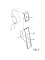
- Fig. 3 illustrates a cross section of the nozzle boot module 1 wherein the lower portion of the first side section 8 extends in front of the receiving section 6 thereby forming the stopper 12.
- the combination of the nozzle boot 2 and the stopper 12 forms a nozzle boot arrangement wherein, when the nozzle is positioned in the nozzle boot 2, the stopper 12 will engage with the spout and thereby prevent the nozzle from rotating about the supporting means 5 and fall out from the nozzle boot arrangement 2.
- the stopper 12 of each nozzle boot arrangement is integrally formed with the side sections 8, 9.
- Each side section 8, 9 forms an outer wall of the nozzle boot module 1 and each nozzle boot arrangement.
- Each stopper 12 thus forms part of an outer wall portion of the nozzle boot module 1 or the nozzle boot arrangement.
- Each nozzle boot arrangement may further comprise detecting means 13 for detecting presence of a nozzle at the nozzle boot.
- the detecting means 13 may communicate with a controller of the fuel dispensing unit wherein a pump of the fuel dispensing unit may be deactivated in response to the detecting means 13 detecting presence of the nozzle and activated in response to the detecting means 13 not detecting presence of the nozzle.
- the detecting means 13 may be arranged at the receiving section 6.
- the detecting means 13 may e.g. comprise a flap, pivotally connected to the section 6 or, alternatively, to a lower portion of the stopper 12.
- the stopper 12 may cooperate with the spout of the nozzle via the flap to prevent the nozzle from rotating and thereby falling out as described above.
- the flap will be actuated by the spout.
- the detecting means 13 may further comprise a magnetic or electrical switch for sensing the actuation of the flap and transmitting a detection signal to the fuel dispensing unit controller.
- the detecting means 13 may also be arranged at the supporting means 5 as illustrated in Fig. 4 .
- the clamp or link In response to the nozzle being removed from supporting means 5 and the flap 14, the clamp or link returns to its unloaded position wherein a magnet is disconnected from the sensor, thus indicating that the nozzle has been removed from the nozzle boot.
- the detecting means 13 may include optical or magnetic sensors provided at the receiving section 6 for detecting presence of the nozzle.
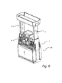
- Fig. 6 illustrates a fuel dispensing unit 16 comprising two nozzle boot modules 1, each module 1 attached to a respective supporting column 4.
- nozzle boot arrangement has been disclosed in connection with the nozzle boot module 1 and the fuel dispensing unit 16.
- the nozzle boot arrangement need not be included in a nozzle boot module but may also be used in non-modular applications.
- a fuel dispensing unit comprising a nozzle boot provided on a side section of the fuel dispensing unit.
- a stopper for preventing the nozzle from falling out from the nozzle boot may form part of an outer wall on a side section of the fuel dispensing unit, the stopper and the nozzle boot together forming a nozzle boot arrangement.
- a nozzle boot body 20 is moulded, the body 20 including a section 6 for receiving at least a portion of the spout.
- the body 20 may be formed by injection moulding.
- the body 20 may be moulded in a single piece.
- the body 20 may be assembled from a plurality of separately moulded body portions.
- the body 20 may be formed in e.g. metal such as aluminium or in plastics.
- the body 20 may be moulded with integral side portions 21, 22. Alternatively, the side portions 21, 22 may be separately formed and attached to the body 20 after moulding thereof.
- the body 20 may further be provided with means for supporting the nozzle at the base portion thereof, the means being similar to the means 5 described in connection with Figs 1-4 .
- the method further comprises forming a stopper 12 separately from the body 20.
- the stopper 12 may e.g. be formed as part of an outer wall of a fuel dispensing unit or a module top of a nozzle boot module.
- the nozzle boot arrangement may then be assembled from the body 20 and the stopper 12 by arranging the stopper 12 at the receiving section 6 such that, when the nozzle boot arrangement is in use and supports a nozzle, the stopper 12 cooperates with the spout in such a manner that fall out of the nozzle from the nozzle boot arrangement by rotation of the nozzle about said supporting means is prevented.
Landscapes
- Engineering & Computer Science (AREA)
- Mechanical Engineering (AREA)
- Fuel-Injection Apparatus (AREA)
- Cooling, Air Intake And Gas Exhaust, And Fuel Tank Arrangements In Propulsion Units (AREA)
- Closures For Containers (AREA)
- Loading And Unloading Of Fuel Tanks Or Ships (AREA)
Claims (19)
- Zapfventilaufnahme-Anordnung zum Stützen eines Zapfventils einer Kraftstoff-Zapfeinheit, wobei das Zapfventil ein Zapfrohr und einem Basisabschnitt einschließlich eines Griffs umfasst, wobei die Anordnung (1) Folgendes umfasst:eine Zapfventilaufnahme (2), die Mittel (5) zum Stützen des Zapfventils am Basisabschnitt desselben und eine Sektion (6) zum Aufnehmen wenigstens eines Abschnitts des Zapfrohrs einschließt,einen Anschlag (12), der an der Aufnahmesektion (6) bereitgestellt wird und dafür angeordnet ist, mit dem Zapfrohr zusammenzuwirken, um zu verhindern, dass das Zapfventil durch eine Drehung des Zapfventils um die Stützmittel (5) aus der Anordnung der Zapfventilaufnahme (2) herausfällt,dadurch gekennzeichnet, dass der Anschlag (12) gesondert von der Zapfventilaufnahme (2) geformt ist.
- Zapfventilaufnahme-Anordnung nach Anspruch 1, wobei der Anschlag (12) einen Teil eines Außenwandabschnitts der Anordnung (1) bildet.
- Zapfventilaufnahme-Anordnung nach einem der Ansprüche 1 bis 2, die ferner Mittel (13) zum Erkennen des Vorhandenseins des Zapfrohrs an der Zapfventilaufnahme (2) umfasst.
- Zapfventilaufnahme-Anordnung nach Anspruch 3, wobei die Mittel (13) zum Erkennen an den Mitteln (5) zum Stützen angeordnet sind.
- Zapfventilaufnahme-Anordnung nach Anspruch 3, wobei die Mittel (13) zum Erkennen an der Aufnahmesektion (6) angeordnet sind.
- Zapfventilaufnahme-Anordnung nach Anspruch 3, wobei die Erkennungsmittel (13) an dem Anschlag (12) angeordnet sind.
- Zapfventilaufnahme-Modul (1), das an einer Kraftstoff-Zapfeinheit (16) befestigt werden kann, wobei das Modul (1) ein Modul-Oberteil (3) und eine Zapfventilaufnahme-Anordnung nach einem der vorhergehenden Ansprüche umfasst, wobei die Anordnung unterhalb des Modul-Oberteils (3) angeordnet ist.
- Zapfventilaufnahme-Modul (1) nach Anspruch 7, wobei das Modul (1) an einer Stützsäule (4) der Kraftstoff-Zapfeinheit (16) befestigt werden kann.
- Zapfventilaufnahme-Modul (1) nach Anspruch 8, wobei das Modul (1) einen Kanal umfasst, der sich durch den Modul-Oberteil (3) erstreckt, wobei der Kanal dafür angeordnet ist, wenigstens einen Abschnitt der Stützsäule (4) aufzunehmen.
- Zapfventilaufnahme-Modul (1) nach einem der Ansprüche 7 bis 9, wobei der Anschlag (12) einen Teil einer Außenwand des Zapfventilaufnahme-Moduls (1) bildet.
- Zapfventilaufnahme-Modul (1) nach einem der Ansprüche 7 bis 10, wobei der Anschlag (12) einen Teil des Modul-Oberteils (3) bildet.
- Zapfventilaufnahme-Modul (1) nach Anspruch 11, wobei der Modul-Oberteil (3) eine obere Sektion (7) und eine erste Seitensektion (8) umfasst, wobei der Anschlag (12) einen Teil der ersten Seitensektion (8) bildet.
- Zapfventilaufnahme-Modul (1) nach Anspruch 12, wobei der Modul-Oberteil (3) ferner eine zweite Seitensektion (9) umfasst und das Modul (1) ferner eine zweite Zapfventilaufnahme-Anordnung nach einem der Ansprüche 1 bis 6 umfasst, wobei ein Anschlag (12) der zweiten Zapfventilaufnahme-Anordnung einen Teil der zweiten Seitensektion (9) bildet.
- Kraftstoff-Zapfeinheit (16), die eine Zapfventilaufnahme-Anordnung nach einem der Ansprüche 1 bis 6 umfasst.
- Kraftstoff-Zapfeinheit (16) nach Anspruch 14, wobei der Anschlag (12) einen Teil einer Außenwand der Kraftstoff-Zapfeinheit (16) bildet.
- Kraftstoff-Zapfeinheit (16), die ein Zapfventilaufnahme-Modul (1) nach einem der Ansprüche 7 bis 13 umfasst.
- Kraftstoff-Zapfeinheit (16), die ein Zapfventilaufnahme-Modul (1) nach einem der Ansprüche 8 bis 9 umfasst, wobei das Zapfventilaufnahme-Modul (1) an der Säule angeordnet ist.
- Verfahren zur Herstellung einer Zapfventilaufnahme-Anordnung nach Anspruch 1 zum Stützen eines Zapfventils einer Kraftstoff-Zapfeinheit, wobei das Zapfventil ein Zapfrohr und einem Basisabschnitt einschließlich eines Griffs umfasst, wobei das Verfahren Folgendes umfasst:das Formen eines Zapfventilaufnahme-Korpus, der eine Sektion (6) zum Aufnehmen wenigstens eines Abschnitts des Zapfrohrs einschließt,das Versehen des Korpus mit Mitteln (5) zum Stützen des Zapfventils an dem Basisabschnitt desselben,das Formen eines Anschlags (12) gesondert von dem Zapfventilaufnahme-Korpus unddas Zusammenbauen der Zapfventilaufnahme-Anordnung aus dem Zapfventilaufnahme-Korpus und dem Anschlag (12) durch das Anordnen des Anschlags (12) an der Aufnahmesektion (6) derart, dass, wenn sich die Zapfventilaufnahme-Anordnung in Verwendung befindet und ein Zapfventil stützt, der Anschlag (12) auf eine solche Weise mit dem Zapfrohr zusammenwirkt, dass ein Herausfallen des Zapfventils aus der Zapfventilaufnahme-Anordnung durch eine Drehung des Zapfventils um die Stützmittel (5) verhindert wird.
- Verfahren nach Anspruch 18, wobei der Zapfventilaufnahme-Korpus in einem einzigen Stück geformt ist.
Applications Claiming Priority (1)
| Application Number | Priority Date | Filing Date | Title |
|---|---|---|---|
| PCT/EP2010/059924 WO2012003886A1 (en) | 2010-07-09 | 2010-07-09 | A nozzle boot arrangement, a nozzle boot module, a fuel dispensing unit, and a method of manufacturing such a nozzle boot arrangement |
Publications (2)
| Publication Number | Publication Date |
|---|---|
| EP2590887A1 EP2590887A1 (de) | 2013-05-15 |
| EP2590887B1 true EP2590887B1 (de) | 2014-06-25 |
Family
ID=43619696
Family Applications (1)
| Application Number | Title | Priority Date | Filing Date |
|---|---|---|---|
| EP10742104.2A Active EP2590887B1 (de) | 2010-07-09 | 2010-07-09 | Vorrichtung zur zapfpistolenaufnahme, zapfpistolenaufnahmemodul und kraftstoffzapfsäule sowie methode zur herstellung einer solchen vorrichtung zur zapfpistolenaufnahme |
Country Status (7)
| Country | Link |
|---|---|
| US (2) | US9010573B2 (de) |
| EP (1) | EP2590887B1 (de) |
| CN (1) | CN103209921A (de) |
| BR (1) | BR112013000641A2 (de) |
| ES (1) | ES2505493T3 (de) |
| PT (1) | PT2590887E (de) |
| WO (1) | WO2012003886A1 (de) |
Families Citing this family (2)
| Publication number | Priority date | Publication date | Assignee | Title |
|---|---|---|---|---|
| IN2012DN03287A (de) | 2009-10-16 | 2015-10-23 | Dresser Wayne Ab | |
| EP2590887B1 (de) * | 2010-07-09 | 2014-06-25 | Dresser Wayne AB | Vorrichtung zur zapfpistolenaufnahme, zapfpistolenaufnahmemodul und kraftstoffzapfsäule sowie methode zur herstellung einer solchen vorrichtung zur zapfpistolenaufnahme |
Family Cites Families (15)
| Publication number | Priority date | Publication date | Assignee | Title |
|---|---|---|---|---|
| US2070560A (en) * | 1931-07-23 | 1937-02-16 | Nat Pumps Corp | Liquid dispensing apparatus |
| US2150025A (en) * | 1936-09-21 | 1939-03-07 | Sf Bowser & Co Inc | Dispensing apparatus |
| US2364138A (en) * | 1942-09-18 | 1944-12-05 | Gilbert & Barker Mfg Co | Liquid dispensing apparatus |
| US2577859A (en) * | 1947-10-25 | 1951-12-11 | Waldo P Schirmer | Hose reel operating mechanism for gasoline pumps |
| US2900111A (en) * | 1956-01-18 | 1959-08-18 | Tokheim Corp | Dispenser nozzle receptacle |
| US3027211A (en) * | 1959-05-27 | 1962-03-27 | Tokheim Corp | Dispenser frame and housing construction |
| US3118570A (en) * | 1961-06-13 | 1964-01-21 | Symington Wayne Corp | Switch-actuating device |
| US4195674A (en) * | 1978-02-15 | 1980-04-01 | Pacific Oil Marketing Equipment Company | Protective hood for a vapor recovery nozzle |
| AU6537680A (en) * | 1979-12-13 | 1981-06-18 | Gilbarco Aust Limited | Pump nozzle retainer |
| US5083846A (en) * | 1990-04-10 | 1992-01-28 | Gilbarco, Inc. | Door panel for multiple product fuel dispensers |
| US5110010A (en) * | 1990-09-21 | 1992-05-05 | Gilbarco, Inc. | Automatic fuel dispenser actuator |
| FR2725974B1 (fr) * | 1994-10-24 | 1997-01-10 | Satam | Dispositif de commande de la pompe d'un distributeur de carburant |
| EP1860058B1 (de) * | 2006-05-24 | 2013-01-02 | Dresser Wayne AB | Herausstehende Zapfpistolenhalterung für eine Zapfsäule |
| ES2425234T3 (es) * | 2008-09-08 | 2013-10-14 | Dresser Wayne Ab | Embudo retenedor de boquilla para un dispensador de combustible |
| EP2590887B1 (de) * | 2010-07-09 | 2014-06-25 | Dresser Wayne AB | Vorrichtung zur zapfpistolenaufnahme, zapfpistolenaufnahmemodul und kraftstoffzapfsäule sowie methode zur herstellung einer solchen vorrichtung zur zapfpistolenaufnahme |
-
2010
- 2010-07-09 EP EP10742104.2A patent/EP2590887B1/de active Active
- 2010-07-09 BR BR112013000641A patent/BR112013000641A2/pt not_active IP Right Cessation
- 2010-07-09 CN CN201080068964XA patent/CN103209921A/zh active Pending
- 2010-07-09 WO PCT/EP2010/059924 patent/WO2012003886A1/en not_active Ceased
- 2010-07-09 PT PT107421042T patent/PT2590887E/pt unknown
- 2010-07-09 US US13/809,401 patent/US9010573B2/en active Active
- 2010-07-09 ES ES10742104.2T patent/ES2505493T3/es active Active
-
2015
- 2015-04-02 US US14/677,218 patent/US9376309B2/en active Active
Also Published As
| Publication number | Publication date |
|---|---|
| CN103209921A (zh) | 2013-07-17 |
| WO2012003886A1 (en) | 2012-01-12 |
| PT2590887E (pt) | 2014-09-29 |
| US20150210530A1 (en) | 2015-07-30 |
| US9376309B2 (en) | 2016-06-28 |
| ES2505493T3 (es) | 2014-10-10 |
| US9010573B2 (en) | 2015-04-21 |
| EP2590887A1 (de) | 2013-05-15 |
| BR112013000641A2 (pt) | 2016-05-24 |
| US20130112706A1 (en) | 2013-05-09 |
Similar Documents
| Publication | Publication Date | Title |
|---|---|---|
| CN203957977U (zh) | 车辆连接架及连接架 | |
| USD614562S1 (en) | Bicycle carrier rack | |
| CN104203770B (zh) | 用于孔锯的悬挂式标签组件 | |
| EP2396235B1 (de) | Stützglied mit einer gel-/flüssigkeits-quetschflasche | |
| US5337954A (en) | Mailbox mounting bracket | |
| EP2590887B1 (de) | Vorrichtung zur zapfpistolenaufnahme, zapfpistolenaufnahmemodul und kraftstoffzapfsäule sowie methode zur herstellung einer solchen vorrichtung zur zapfpistolenaufnahme | |
| US20070145085A1 (en) | Hanger with ratcheting sliding-jaw clamps | |
| AU2002357963B2 (en) | Shopping cart | |
| US20050230577A1 (en) | Hanger for use on metal rack | |
| CN103363754B (zh) | 冰箱 | |
| CN103528319A (zh) | 冰箱 | |
| USD492833S1 (en) | Rider pallet truck | |
| GB2437831A (en) | Garment hanger with indicator tab | |
| USD592468S1 (en) | Wine rack | |
| EP3401187A1 (de) | Fahrbarer wagen und verfahren zur herstellung davon | |
| CN102997580A (zh) | 冰箱 | |
| US20070084889A1 (en) | Information display cap for a hanger | |
| US20090071864A1 (en) | Mechanism for Permanently Attaching a Blister Card within a Container | |
| US7617627B1 (en) | Display assembly | |
| CN107207144B (zh) | 用于供液体用的运输和储存容器的托盘状的底架 | |
| CN211493780U (zh) | 汽车及汽车杯托 | |
| CA2494964A1 (en) | Adapter for mounting items on a steering column | |
| USD539504S1 (en) | Overhead guard for a materials handling vehicle | |
| CN204478700U (zh) | 冰箱的抽屉和具有它的冰箱 | |
| USD554039S1 (en) | Bicycle stabilizer wheel mounting bracket |
Legal Events
| Date | Code | Title | Description |
|---|---|---|---|
| PUAI | Public reference made under article 153(3) epc to a published international application that has entered the european phase |
Free format text: ORIGINAL CODE: 0009012 |
|
| 17P | Request for examination filed |
Effective date: 20130207 |
|
| AK | Designated contracting states |
Kind code of ref document: A1 Designated state(s): AL AT BE BG CH CY CZ DE DK EE ES FI FR GB GR HR HU IE IS IT LI LT LU LV MC MK MT NL NO PL PT RO SE SI SK SM TR |
|
| DAX | Request for extension of the european patent (deleted) | ||
| REG | Reference to a national code |
Ref country code: DE Ref legal event code: R079 Ref document number: 602010017018 Country of ref document: DE Free format text: PREVIOUS MAIN CLASS: B67D0007060000 Ipc: B67D0007420000 |
|
| RIC1 | Information provided on ipc code assigned before grant |
Ipc: B67D 7/42 20100101AFI20131211BHEP Ipc: B67D 7/06 20100101ALI20131211BHEP Ipc: B67D 7/84 20100101ALI20131211BHEP |
|
| GRAP | Despatch of communication of intention to grant a patent |
Free format text: ORIGINAL CODE: EPIDOSNIGR1 |
|
| INTG | Intention to grant announced |
Effective date: 20140120 |
|
| GRAS | Grant fee paid |
Free format text: ORIGINAL CODE: EPIDOSNIGR3 |
|
| GRAA | (expected) grant |
Free format text: ORIGINAL CODE: 0009210 |
|
| AK | Designated contracting states |
Kind code of ref document: B1 Designated state(s): AL AT BE BG CH CY CZ DE DK EE ES FI FR GB GR HR HU IE IS IT LI LT LU LV MC MK MT NL NO PL PT RO SE SI SK SM TR |
|
| REG | Reference to a national code |
Ref country code: GB Ref legal event code: FG4D |
|
| REG | Reference to a national code |
Ref country code: CH Ref legal event code: EP |
|
| REG | Reference to a national code |
Ref country code: AT Ref legal event code: REF Ref document number: 674544 Country of ref document: AT Kind code of ref document: T Effective date: 20140715 |
|
| REG | Reference to a national code |
Ref country code: IE Ref legal event code: FG4D |
|
| REG | Reference to a national code |
Ref country code: DE Ref legal event code: R096 Ref document number: 602010017018 Country of ref document: DE Effective date: 20140807 |
|
| REG | Reference to a national code |
Ref country code: PT Ref legal event code: SC4A Free format text: AVAILABILITY OF NATIONAL TRANSLATION Effective date: 20140922 |
|
| REG | Reference to a national code |
Ref country code: ES Ref legal event code: FG2A Ref document number: 2505493 Country of ref document: ES Kind code of ref document: T3 Effective date: 20141010 |
|
| PG25 | Lapsed in a contracting state [announced via postgrant information from national office to epo] |
Ref country code: GR Free format text: LAPSE BECAUSE OF FAILURE TO SUBMIT A TRANSLATION OF THE DESCRIPTION OR TO PAY THE FEE WITHIN THE PRESCRIBED TIME-LIMIT Effective date: 20140926 Ref country code: CY Free format text: LAPSE BECAUSE OF FAILURE TO SUBMIT A TRANSLATION OF THE DESCRIPTION OR TO PAY THE FEE WITHIN THE PRESCRIBED TIME-LIMIT Effective date: 20140625 Ref country code: FI Free format text: LAPSE BECAUSE OF FAILURE TO SUBMIT A TRANSLATION OF THE DESCRIPTION OR TO PAY THE FEE WITHIN THE PRESCRIBED TIME-LIMIT Effective date: 20140625 Ref country code: LT Free format text: LAPSE BECAUSE OF FAILURE TO SUBMIT A TRANSLATION OF THE DESCRIPTION OR TO PAY THE FEE WITHIN THE PRESCRIBED TIME-LIMIT Effective date: 20140625 Ref country code: NO Free format text: LAPSE BECAUSE OF FAILURE TO SUBMIT A TRANSLATION OF THE DESCRIPTION OR TO PAY THE FEE WITHIN THE PRESCRIBED TIME-LIMIT Effective date: 20140925 |
|
| PGFP | Annual fee paid to national office [announced via postgrant information from national office to epo] |
Ref country code: DE Payment date: 20140903 Year of fee payment: 5 |
|
| RAP2 | Party data changed (patent owner data changed or rights of a patent transferred) |
Owner name: WAYNE FUELING SYSTEMS SWEDEN AB |
|
| REG | Reference to a national code |
Ref country code: AT Ref legal event code: MK05 Ref document number: 674544 Country of ref document: AT Kind code of ref document: T Effective date: 20140625 |
|
| REG | Reference to a national code |
Ref country code: NL Ref legal event code: VDEP Effective date: 20140625 |
|
| REG | Reference to a national code |
Ref country code: LT Ref legal event code: MG4D |
|
| PG25 | Lapsed in a contracting state [announced via postgrant information from national office to epo] |
Ref country code: HR Free format text: LAPSE BECAUSE OF FAILURE TO SUBMIT A TRANSLATION OF THE DESCRIPTION OR TO PAY THE FEE WITHIN THE PRESCRIBED TIME-LIMIT Effective date: 20140625 Ref country code: SE Free format text: LAPSE BECAUSE OF FAILURE TO SUBMIT A TRANSLATION OF THE DESCRIPTION OR TO PAY THE FEE WITHIN THE PRESCRIBED TIME-LIMIT Effective date: 20140625 Ref country code: LV Free format text: LAPSE BECAUSE OF FAILURE TO SUBMIT A TRANSLATION OF THE DESCRIPTION OR TO PAY THE FEE WITHIN THE PRESCRIBED TIME-LIMIT Effective date: 20140625 |
|
| PGFP | Annual fee paid to national office [announced via postgrant information from national office to epo] |
Ref country code: TR Payment date: 20140922 Year of fee payment: 5 |
|
| PGFP | Annual fee paid to national office [announced via postgrant information from national office to epo] |
Ref country code: PT Payment date: 20140926 Year of fee payment: 5 |
|
| PG25 | Lapsed in a contracting state [announced via postgrant information from national office to epo] |
Ref country code: EE Free format text: LAPSE BECAUSE OF FAILURE TO SUBMIT A TRANSLATION OF THE DESCRIPTION OR TO PAY THE FEE WITHIN THE PRESCRIBED TIME-LIMIT Effective date: 20140625 Ref country code: SK Free format text: LAPSE BECAUSE OF FAILURE TO SUBMIT A TRANSLATION OF THE DESCRIPTION OR TO PAY THE FEE WITHIN THE PRESCRIBED TIME-LIMIT Effective date: 20140625 Ref country code: RO Free format text: LAPSE BECAUSE OF FAILURE TO SUBMIT A TRANSLATION OF THE DESCRIPTION OR TO PAY THE FEE WITHIN THE PRESCRIBED TIME-LIMIT Effective date: 20140625 |
|
| PGFP | Annual fee paid to national office [announced via postgrant information from national office to epo] |
Ref country code: ES Payment date: 20141027 Year of fee payment: 5 Ref country code: CZ Payment date: 20140917 Year of fee payment: 5 |
|
| PG25 | Lapsed in a contracting state [announced via postgrant information from national office to epo] |
Ref country code: AT Free format text: LAPSE BECAUSE OF FAILURE TO SUBMIT A TRANSLATION OF THE DESCRIPTION OR TO PAY THE FEE WITHIN THE PRESCRIBED TIME-LIMIT Effective date: 20140625 Ref country code: PL Free format text: LAPSE BECAUSE OF FAILURE TO SUBMIT A TRANSLATION OF THE DESCRIPTION OR TO PAY THE FEE WITHIN THE PRESCRIBED TIME-LIMIT Effective date: 20140625 Ref country code: NL Free format text: LAPSE BECAUSE OF FAILURE TO SUBMIT A TRANSLATION OF THE DESCRIPTION OR TO PAY THE FEE WITHIN THE PRESCRIBED TIME-LIMIT Effective date: 20140625 Ref country code: IS Free format text: LAPSE BECAUSE OF FAILURE TO SUBMIT A TRANSLATION OF THE DESCRIPTION OR TO PAY THE FEE WITHIN THE PRESCRIBED TIME-LIMIT Effective date: 20141025 |
|
| REG | Reference to a national code |
Ref country code: CH Ref legal event code: PL |
|
| REG | Reference to a national code |
Ref country code: DE Ref legal event code: R097 Ref document number: 602010017018 Country of ref document: DE |
|
| PG25 | Lapsed in a contracting state [announced via postgrant information from national office to epo] |
Ref country code: MC Free format text: LAPSE BECAUSE OF FAILURE TO SUBMIT A TRANSLATION OF THE DESCRIPTION OR TO PAY THE FEE WITHIN THE PRESCRIBED TIME-LIMIT Effective date: 20140625 |
|
| REG | Reference to a national code |
Ref country code: IE Ref legal event code: MM4A |
|
| PG25 | Lapsed in a contracting state [announced via postgrant information from national office to epo] |
Ref country code: DK Free format text: LAPSE BECAUSE OF FAILURE TO SUBMIT A TRANSLATION OF THE DESCRIPTION OR TO PAY THE FEE WITHIN THE PRESCRIBED TIME-LIMIT Effective date: 20140625 Ref country code: IT Free format text: LAPSE BECAUSE OF FAILURE TO SUBMIT A TRANSLATION OF THE DESCRIPTION OR TO PAY THE FEE WITHIN THE PRESCRIBED TIME-LIMIT Effective date: 20140625 Ref country code: CH Free format text: LAPSE BECAUSE OF NON-PAYMENT OF DUE FEES Effective date: 20140731 Ref country code: LI Free format text: LAPSE BECAUSE OF NON-PAYMENT OF DUE FEES Effective date: 20140731 |
|
| PLBE | No opposition filed within time limit |
Free format text: ORIGINAL CODE: 0009261 |
|
| STAA | Information on the status of an ep patent application or granted ep patent |
Free format text: STATUS: NO OPPOSITION FILED WITHIN TIME LIMIT |
|
| 26N | No opposition filed |
Effective date: 20150326 |
|
| PG25 | Lapsed in a contracting state [announced via postgrant information from national office to epo] |
Ref country code: BE Free format text: LAPSE BECAUSE OF FAILURE TO SUBMIT A TRANSLATION OF THE DESCRIPTION OR TO PAY THE FEE WITHIN THE PRESCRIBED TIME-LIMIT Effective date: 20140625 |
|
| PG25 | Lapsed in a contracting state [announced via postgrant information from national office to epo] |
Ref country code: IE Free format text: LAPSE BECAUSE OF NON-PAYMENT OF DUE FEES Effective date: 20140709 |
|
| PG25 | Lapsed in a contracting state [announced via postgrant information from national office to epo] |
Ref country code: SI Free format text: LAPSE BECAUSE OF FAILURE TO SUBMIT A TRANSLATION OF THE DESCRIPTION OR TO PAY THE FEE WITHIN THE PRESCRIBED TIME-LIMIT Effective date: 20140625 |
|
| REG | Reference to a national code |
Ref country code: DE Ref legal event code: R119 Ref document number: 602010017018 Country of ref document: DE |
|
| REG | Reference to a national code |
Ref country code: PT Ref legal event code: MM4A Free format text: LAPSE DUE TO NON-PAYMENT OF FEES Effective date: 20160411 |
|
| PG25 | Lapsed in a contracting state [announced via postgrant information from national office to epo] |
Ref country code: SM Free format text: LAPSE BECAUSE OF FAILURE TO SUBMIT A TRANSLATION OF THE DESCRIPTION OR TO PAY THE FEE WITHIN THE PRESCRIBED TIME-LIMIT Effective date: 20140625 Ref country code: CZ Free format text: LAPSE BECAUSE OF NON-PAYMENT OF DUE FEES Effective date: 20150709 Ref country code: DE Free format text: LAPSE BECAUSE OF NON-PAYMENT OF DUE FEES Effective date: 20160202 |
|
| PG25 | Lapsed in a contracting state [announced via postgrant information from national office to epo] |
Ref country code: MT Free format text: LAPSE BECAUSE OF FAILURE TO SUBMIT A TRANSLATION OF THE DESCRIPTION OR TO PAY THE FEE WITHIN THE PRESCRIBED TIME-LIMIT Effective date: 20140625 Ref country code: BG Free format text: LAPSE BECAUSE OF FAILURE TO SUBMIT A TRANSLATION OF THE DESCRIPTION OR TO PAY THE FEE WITHIN THE PRESCRIBED TIME-LIMIT Effective date: 20140625 |
|
| REG | Reference to a national code |
Ref country code: FR Ref legal event code: PLFP Year of fee payment: 7 |
|
| PG25 | Lapsed in a contracting state [announced via postgrant information from national office to epo] |
Ref country code: HU Free format text: LAPSE BECAUSE OF FAILURE TO SUBMIT A TRANSLATION OF THE DESCRIPTION OR TO PAY THE FEE WITHIN THE PRESCRIBED TIME-LIMIT; INVALID AB INITIO Effective date: 20100709 Ref country code: LU Free format text: LAPSE BECAUSE OF NON-PAYMENT OF DUE FEES Effective date: 20140709 |
|
| REG | Reference to a national code |
Ref country code: ES Ref legal event code: FD2A Effective date: 20160826 |
|
| PG25 | Lapsed in a contracting state [announced via postgrant information from national office to epo] |
Ref country code: PT Free format text: LAPSE BECAUSE OF NON-PAYMENT OF DUE FEES Effective date: 20160411 |
|
| PG25 | Lapsed in a contracting state [announced via postgrant information from national office to epo] |
Ref country code: ES Free format text: LAPSE BECAUSE OF NON-PAYMENT OF DUE FEES Effective date: 20150710 |
|
| REG | Reference to a national code |
Ref country code: FR Ref legal event code: PLFP Year of fee payment: 8 |
|
| PG25 | Lapsed in a contracting state [announced via postgrant information from national office to epo] |
Ref country code: TR Free format text: LAPSE BECAUSE OF NON-PAYMENT OF DUE FEES Effective date: 20150709 |
|
| PG25 | Lapsed in a contracting state [announced via postgrant information from national office to epo] |
Ref country code: MK Free format text: LAPSE BECAUSE OF FAILURE TO SUBMIT A TRANSLATION OF THE DESCRIPTION OR TO PAY THE FEE WITHIN THE PRESCRIBED TIME-LIMIT Effective date: 20140625 |
|
| REG | Reference to a national code |
Ref country code: FR Ref legal event code: PLFP Year of fee payment: 9 |
|
| PG25 | Lapsed in a contracting state [announced via postgrant information from national office to epo] |
Ref country code: AL Free format text: LAPSE BECAUSE OF FAILURE TO SUBMIT A TRANSLATION OF THE DESCRIPTION OR TO PAY THE FEE WITHIN THE PRESCRIBED TIME-LIMIT Effective date: 20140625 |
|
| REG | Reference to a national code |
Ref country code: GB Ref legal event code: 732E Free format text: REGISTERED BETWEEN 20220901 AND 20220907 |
|
| P01 | Opt-out of the competence of the unified patent court (upc) registered |
Effective date: 20230529 |
|
| PGFP | Annual fee paid to national office [announced via postgrant information from national office to epo] |
Ref country code: GB Payment date: 20250722 Year of fee payment: 16 |
|
| PGFP | Annual fee paid to national office [announced via postgrant information from national office to epo] |
Ref country code: FR Payment date: 20250725 Year of fee payment: 16 |