EP2590019A2 - Projector device, distortion correction method, and distortion correction program - Google Patents
Projector device, distortion correction method, and distortion correction program Download PDFInfo
- Publication number
- EP2590019A2 EP2590019A2 EP12188751.7A EP12188751A EP2590019A2 EP 2590019 A2 EP2590019 A2 EP 2590019A2 EP 12188751 A EP12188751 A EP 12188751A EP 2590019 A2 EP2590019 A2 EP 2590019A2
- Authority
- EP
- European Patent Office
- Prior art keywords
- projector device
- projector
- image
- distortion
- timer value
- Prior art date
- Legal status (The legal status is an assumption and is not a legal conclusion. Google has not performed a legal analysis and makes no representation as to the accuracy of the status listed.)
- Granted
Links
- 238000000034 method Methods 0.000 title claims abstract description 11
- 238000004590 computer program Methods 0.000 claims description 3
- 230000001133 acceleration Effects 0.000 description 8
- 238000001514 detection method Methods 0.000 description 5
- 238000005516 engineering process Methods 0.000 description 5
- 230000003287 optical effect Effects 0.000 description 4
- 230000015556 catabolic process Effects 0.000 description 2
- 238000006731 degradation reaction Methods 0.000 description 2
- 239000003086 colorant Substances 0.000 description 1
- 238000010586 diagram Methods 0.000 description 1
- 230000006870 function Effects 0.000 description 1
- 230000005484 gravity Effects 0.000 description 1
- 229910052736 halogen Inorganic materials 0.000 description 1
- 150000002367 halogens Chemical class 0.000 description 1
- 239000004973 liquid crystal related substance Substances 0.000 description 1
- 239000000463 material Substances 0.000 description 1
- QSHDDOUJBYECFT-UHFFFAOYSA-N mercury Chemical compound [Hg] QSHDDOUJBYECFT-UHFFFAOYSA-N 0.000 description 1
- 229910052753 mercury Inorganic materials 0.000 description 1
- 229910001507 metal halide Inorganic materials 0.000 description 1
- 150000005309 metal halides Chemical class 0.000 description 1
- 238000005070 sampling Methods 0.000 description 1
- 230000035939 shock Effects 0.000 description 1
- 230000003068 static effect Effects 0.000 description 1
Images



Classifications
-
- G—PHYSICS
- G03—PHOTOGRAPHY; CINEMATOGRAPHY; ANALOGOUS TECHNIQUES USING WAVES OTHER THAN OPTICAL WAVES; ELECTROGRAPHY; HOLOGRAPHY
- G03B—APPARATUS OR ARRANGEMENTS FOR TAKING PHOTOGRAPHS OR FOR PROJECTING OR VIEWING THEM; APPARATUS OR ARRANGEMENTS EMPLOYING ANALOGOUS TECHNIQUES USING WAVES OTHER THAN OPTICAL WAVES; ACCESSORIES THEREFOR
- G03B21/00—Projectors or projection-type viewers; Accessories therefor
- G03B21/14—Details
- G03B21/147—Optical correction of image distortions, e.g. keystone
-
- G—PHYSICS
- G03—PHOTOGRAPHY; CINEMATOGRAPHY; ANALOGOUS TECHNIQUES USING WAVES OTHER THAN OPTICAL WAVES; ELECTROGRAPHY; HOLOGRAPHY
- G03B—APPARATUS OR ARRANGEMENTS FOR TAKING PHOTOGRAPHS OR FOR PROJECTING OR VIEWING THEM; APPARATUS OR ARRANGEMENTS EMPLOYING ANALOGOUS TECHNIQUES USING WAVES OTHER THAN OPTICAL WAVES; ACCESSORIES THEREFOR
- G03B21/00—Projectors or projection-type viewers; Accessories therefor
- G03B21/14—Details
- G03B21/145—Housing details, e.g. position adjustments thereof
-
- H—ELECTRICITY
- H04—ELECTRIC COMMUNICATION TECHNIQUE
- H04N—PICTORIAL COMMUNICATION, e.g. TELEVISION
- H04N9/00—Details of colour television systems
- H04N9/12—Picture reproducers
- H04N9/31—Projection devices for colour picture display, e.g. using electronic spatial light modulators [ESLM]
- H04N9/3179—Video signal processing therefor
- H04N9/3185—Geometric adjustment, e.g. keystone or convergence
-
- H—ELECTRICITY
- H04—ELECTRIC COMMUNICATION TECHNIQUE
- H04N—PICTORIAL COMMUNICATION, e.g. TELEVISION
- H04N9/00—Details of colour television systems
- H04N9/12—Picture reproducers
- H04N9/31—Projection devices for colour picture display, e.g. using electronic spatial light modulators [ESLM]
- H04N9/3191—Testing thereof
- H04N9/3194—Testing thereof including sensor feedback
Definitions
- the present invention generally relates to a projector device capable of correcting trapezoidal distortion in an image to be projected, a method of correcting trapezoidal distortion in an image to be projected, and a recording medium storing a distortion correction program.
- the recent projector devices are provided with a keystone distortion correction function, which corrects trapezoidal distortion in an image to be projected.
- the projector device detects an inclination angle of the projector device using an accelerometer, corrects trapezoidal distortion in the image based on the detected inclination angle, and projects the corrected image on a screen.
- the accelerometer does not only detect static acceleration due to gravity, but also detects dynamic acceleration due to vibration or shock. For this reasons, even when a table on which the projector device is provided vibrates even slightly, the projector device performs distortion correction. This may sometimes lower the quality of the projection image being displayed on the screen, as the projection image is constantly updated.
- Japanese Patent Application Publication No. JP 2005-79939-A obtains the output signal of an accelerometer for a plurality of times, and corrects trapezoidal distortion based on the value of output signal that occurs most frequently, thus reducing the number of times the projector device performs distortion correction.
- the projector device disclosed in Japanese Patent Application Publication No. JP 2005-79939-A corrects trapezoidal distortion based on the value of output signal that occurs most frequently, irrespective of the cause of a vibration.
- the projector device is provided with an operation device, for example, at the upper surface of the projector device to allow a user to input a user instruction through a key or a switch.
- the projector device may be slightly vibrated such that the accelerometer may detect such vibration.
- the accelerometer may output an inclination angle of the projector device as large as one degree. Accordingly, the projector device performs distortion correction based on this inclination angle, such that it may degrade image quality of the projection image as distortion correction is performed more than it is needed.
- one aspect of the present invention is to provide a projector device, which determines whether the operation device of the projector device is being operated by the user to generate a determination result, and prohibits the projector device from performing distortion correction when the determination result indicates that the operation device is being operated by the user.
- FIG. 1 is a schematic block diagram illustrating a structure of a projector device, according to an example embodiment of the present invention
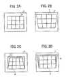
- FIG. 2A is an illustration of an image formed on an image forming section of a light valve of the projector device of FIG. 1 ;
- FIG. 2B is an illustration of a projection image displayed on a screen based on the image of FIG. 2A , which is distorted;
- FIG. 2C is an illustration of a corrected image formed on the image forming section of the light valve of the projector device of FIG. 1 ;
- FIG. 2D is an illustration of a projection image displayed on the screen based on the corrected image of FIG. 2C ;
- FIG. 3A is an illustration for explaining operation of detecting an inclination angle of the projector device of FIG. 1 , when the projector device of FIG. 1 is provided in substantially perpendicular with respect to a horizontal surface;
- FIG. 3B is an illustration for explaining operation of detecting an inclination angle of the projector device of FIG. 1 , when the projector device of FIG. 1 is inclined with respect to the horizontal surface;
- FIG. 4 is a flowchart illustrating operation of correcting trapezoidal distortion in an image, performed by the projector device of FIG. 1 , according to an example embodiment of the present invention.
- FIGs. 5A and 5B are an illustration for explaining the relationship between a minimum angle and a projection distance of the projector device of FIG. 1 , using a projection image displayed on the screen.
- the projector device 1 of FIG. 1 projects an image using the liquid crystal display (LCD) technology.
- the projector device 1 of FIG. 1 may use any desired projection technologies including digital light processing (DLP) technology using one or more digital micro mirror devices (DMDs).
- DLP digital light processing
- DMDs digital micro mirror devices
- the projector device 1 includes a projector 80, an image input 40, a distortion corrector 50, an operation device 60, and an angle detector 70.
- the projector 80 includes a light source 10, a LCD light valve ("light valve") 20, and a projection optical system 30.
- the light source 10 is provided with a lamp, and a light polarizing element that converts light irradiated from the lamp to linear polarized light.
- the lamp may be implemented by, for example, a halogen lamp.
- the other examples of lamp include, but not limited to, metal halide lamp, high-pressure mercury lamp, laser, and light emitting diode (LED).
- the light valve 20 is provided with an image forming section 21 ( FIG. 2 ).
- the light valve 20 forms an image 22 on the image forming section 21, based on information output from the distortion corrector 50. Unless the image is corrected at the distortion corrector 50, the light valve 20 forms the image 22 on the image forming section 21 based on image data input by the image input 40.
- the projection optical system 30 includes a lens system 31, a focus adjuster 32, and a zoom adjuster 33.
- the focus adjuster 32 adjusts the focus of a projection image 3 displayed on a screen 2.
- the zoom adjuster 33 enlarges or reduces the size of the projection image 3 displayed on the screen 2 by zooming in or out.
- the light irradiated from the light source 10 is directed to the image 22 on the image forming section 21, as the light passes the image forming section 21 of the light valve 20.
- the projection optical system 30 projects the image 22, which is irradiated with the light, toward the outside to display the image 22 as the projection image 3 on the screen 2.
- the projector 80 projects the projection image 3 on the screen 2, which is substantially perpendicular with respect to the floor or the ceiling of a room where the projector device 1 is provided.
- the image input 40 inputs the image data output from an image output device such as a personal computer (PC) 4.
- the other examples of the image output device include, but not limited to, a DVD player, video player, and television.
- the image input 40 may input image data, which is received through a network.
- the distortion corrector 50 is implemented by processor.
- the processor includes a central processing unit (CPU), a read only memory (ROM) that stores various control programs, a random access memory (RAM) that temporarily stores data, a backup memory, an input port, and an output port.
- CPU central processing unit
- ROM read only memory
- RAM random access memory
- the ROM stores a control program that causes the distortion corrector 50 to execute operation of correcting geometric distortion such as trapezoidal distortion in an image.
- the CPU deploys the distortion correction control program stored in the ROM onto the RAM functioning as a work memory area to perform various operations including adjusting a correction amount based on angle information input by the angle detector 70 or an instruction obtained through the operation device 60, and correcting distortion in the image input by the image input 40.
- the distortion corrector 50 corrects trapezoidal distortion in the projection image 3 to be displayed or being displayed on the screen 2, based on an inclination angle "X" of the projector 80 that is detected by the accelerometer 71.
- the accelerometer 71 is capable of detecting the inclination angle of the projector 80 in the up or down directions with respect to a horizontal surface. For example, the distortion corrector 50 obtains an inclination angle value X that is detected by the accelerometer 71 once every 100 milliseconds.
- the distortion corrector 50 sets a border section 22a (hatched area) of the image 22 formed on the image forming section 21 of the light valve 20 to black colors, based on the inclination angle of the projector device 1.
- the border section 22a of the image 22 is displayed as a border section 3a of the projection image 3, in black color.
- the rest of the projection image 3, from which the border section 22a is removed, is displayed in color based on the original image. Since the border section 3a is displayed in black, the user is most likely to think that the projection image 3 is in rectangular shape.
- the distortion corrector 50 when the detected inclination angle X of the projector 80 has a value greater than the minimum angle value ⁇ , the distortion corrector 50 performs distortion correction. More specifically, when the detected inclination angle X of the projector device 1 is greater than the minimum angle value ⁇ , the distortion corrector 50 corrects distortion in the projection image 3.
- the minimum angle value ⁇ is previously determined depending on a projection distance L0 of the projector device 1.
- the projector 80 is tilted at a slight angle even when the projector device 1 is provided at a horizontal surface.
- the minimum angle value needs to be taken into account in addition to a projection angle ⁇ of the projector 80.
- the distortion corrector 50 may calculate the minimum angle value ⁇ of the detected inclination angle X that defines an inclination angle value subjected for distortion correction, using the following equation.
- the line “V” indicates a vertical line, or substantially a vertical line.
- the line “H” indicates a horizontal line, or substantially a horizontal line.
- ⁇ denotes the minimum angle value of inclination angle X that defines an inclination angle value subjected for distortion correction ( FIG. 5B ).
- ⁇ denotes the distorted angle of the projection image 3, which reflects the degree of distortion in the projection image 3 ( FIG. 5A ).
- Wt denotes a half of the upper side length of the projection image 3 ( FIG. 5A ).
- Wb denotes a half of the lower side length of the projection image 3 ( FIG. 5A ).
- ⁇ denotes a projection angle of the projector 80 in the projector device 1 ( FIG. 5B ).
- L0 denotes a projection distance of the projector device 1, which is obtained as a distance between the projector 80 and the projection image 3 ( FIG. 5B ).
- the distorted angle ⁇ of the projection image 3 is about 0.5 degrees.
- the distortion corrector 50 further detects an operation state of the operation device 60 to determine whether the operation device 60 is being operated by the user. In one example, the distortion corrector 50 determines that the operation device 60 is being operated by the user when any one of the keys has changed its state, such as from the off-state to the on-state, or from the on-state to the off-state. When it is determined that the operation device 60 is being operated by the user, the distortion corrector 50 does not perform distortion correction on the projection image 3.
- the distortion corrector 50 is further provided with a waiting time period timer, which counts a timer value to be used for indicating a waiting time period.
- the waiting time period timer may be turned on or off according to an instruction of the distortion corrector 50. Further, the on or off state of the waiting time period timer is reflected to the on or off state of a waiting time period timer flag stored in a memory of the distortion corrector 50.
- the distortion corrector 50 is able to determine whether the waiting time period timer is in the on state or off state, based on the value of waiting time period timer flag.
- the distortion corrector 50 starts counting a timer value for a waiting time period by starting the waiting time period timer when it is determined that the user completes operating the operation device 60. In this manner, when it is determined that the operation device 60 is being operated by the user, the distortion corrector 50 stops performing distortion correction operation for a predetermined waiting time period, which is previously set.
- the predetermined waiting time period may be set, for example, at 2 seconds.
- the operation device 60 is provided with a power switch and various adjuster keys 61, which are respectively formed on the upper surface of the projector device 1.
- the adjuster keys 61 include, for example, a zoom key for zooming in or out the projection image 3, a correction key for instructing distortion correction of the projection image 3, and a focus key for focusing the projection image 3.
- the projector device 1 may correct distortion in the image according to a user instruction. For example, after distortion in the projection image 3 is automatically corrected by the distortion corrector 50, the user may manually adjust the projection image 3 through the operation device 60 provided on the surface of the projector device 1.
- the operation device 60 may be remotely controlled using a remote controller.
- the angle detector 70 is provided with the accelerometer 71.
- the accelerometer 71 detects an inclination angle of the projector device 1, which indicates the degree of tilt of the projector 80 with respect to the horizontal surface.
- the angle detector 70 obtains inclination angle information regarding the inclination angle detected by the accelerometer 71, and outputs the inclination angle information to the distortion corrector 50.
- the accelerometer 71 has a resolution capability, which is set at an angle smaller than the minimum angle value ⁇ , such as at 0.1 degrees.
- the accelerometer 71 is implemented by an analog single-axis accelerometer, which outputs a voltage that is proportional to acceleration.
- the accelerometer 71 may be provided with any desired number of detection axis such as two or three axes, or may output the detection result in any other form such as in digital form based on the duty cycle.
- the accelerometer 71 is incorporated in the inner body of the projector device 1.
- the accelerometer 71 detects acceleration that acts along the axis 1a of the projector device 1.
- the axis 1a runs horizontally through the body of the projector device 1.
- the projector device 1 projects the projection image 3 while facing upward.
- an acceleration component that acts on the back portion of the projector device 1 is g*sinX.
- the accelerometer 71 outputs a voltage that is proportional to the acceleration component.
- the angle detector 70 detects an inclination angle of the projector device 1, based on the voltage output from the accelerometer 71.
- FIG. 4 operation of correcting trapezoidal distortion in the image to be projected, performed by the projector device 1, is explained according to an example embodiment of the present invention.
- the minimum angle value ⁇ is stored in a memory such as the RAM of the processing functioning as the distortion corrector 50.
- the distortion corrector 50 detects an operation state of the operation device 60 to determine whether the operation device 60 is in operation. More specifically, in this example, the operation device 60 is in operation when the operation device 60 is receiving a user instruction as the user operates the operation device 60. For example, the distortion corrector 50 may determine whether there is any signal that is output by the operation device 60, which indicates the user input to the operation device 60. When it is determined that the operation device 60 is in operation ("YES" at S1), the operation ends without performing distortion correction. When it is determined that the operation device 60 is not in operation ("NO" at S1), the operation proceeds to S2.
- the distortion corrector 50 is prohibited from performing trapezoidal distortion correction such that operation of trapezoidal distortion correction is stopped.
- the distortion corrector 50 determines whether the waiting time period timer ("waiting time timer") is in operation such that a timer value is counted. For example, the distortion corrector 50 refers to the value of waiting time period timer flag to determine whether the waiting time period timer is in operation.
- the operation proceeds to S3 to start counting a timer value for a waiting time period by executing the waiting time period timer.
- the operation proceeds to S4.
- the distortion corrector 50 determines whether the counted timer value of the waiting time period timer is within a predetermined timer value.
- the predetermined timer value is set at 2 seconds.
- the operation ends without performing distortion correction. More specifically, when it is determined that the timer value is within the predetermined timer value, the distortion corrector 50 is prohibited from performing trapezoidal distortion correction such that operation of trapezoidal distortion correction is stopped.
- the operation proceeds to S5 to stop counting the counter timer value, by stopping the waiting time period timer.
- the distortion corrector 50 starts or resumes distortion correction operation.
- the angle detector 70 detects an inclination angle X of the projector 80 of the projector device 1 using the accelerometer 71, under control of the distortion corrector 50.
- the distortion corrector 50 may instruct the angle detector 70 to send inclination angle information.
- the angle detector 70 inputs the detected inclination angle value X to the distortion corrector 50.
- the distortion corrector 50 corrects trapezoidal distortion in the image to be projected based on the input inclination angle value X.
- the distortion corrector 50 corrects the image 22 formed on the image forming section 21 of the light valve 20 using any desired known technique.
- the distortion corrector 50 is prohibited from performing distortion correction on the projection image 3 when the operation device 60 is in operation. Further, the distortion corrector 50 is prohibited from performing distortion correction on the projection image 3 for the predetermined waiting time period after the user completes operating the operation device 60. Accordingly, the projector device 1 does not repeat operation of correction distortion in the image to be projected even when a small vibration occurs due to user's input to the operation device 60. This suppresses degradation in image quality of the projection image 3, which may be otherwise caused by repeating operation of correction distortion more than it is needed.
- the projector 80 of the projector device 1 may be slightly vibrated as a force is exerted on a circuit board or a casing of the projector device 1.
- the projector device 1 does not correct distortion that may be caused due to the user input to the operation device 60.
- the distortion corrector 50 performs operation of correcting distortion in the projection image such that the image quality of the projection image 3 is kept at a sufficient level.
- the waiting time period is set at 2 seconds.
- any desired value greater than 0 may be set.
- the waiting time period may be preferably set at 1 to 3 seconds, and more preferably set at 2 seconds.
- no waiting time period may be set.
- the distortion corrector 50 may perform distortion correction based on a detection result of the accelerometer 71.
- the projector device 1 may be made of material that hardly vibrates even when there is user input to the operation device 60.
- the distortion corrector 50 may be programmed to perform distortion correction when the operation device 60 is not in operation. This may simplify operation of controlling distortion correction.
- tan ⁇ (Wt-Wb)/(L0*(tan( ⁇ + ⁇ )-tan ⁇ ))
- the projection angle ⁇ is greatly influenced by the value of projection distance L0. Accordingly, especially when the very short-focal length projector or the short-focal length projector is used, controlling distortion correction using the minimum angle value ⁇ as described above can further improve the image quality of the projection image 3.
- the inclination angle X is detected once every 100 milliseconds.
- any desired sampling time period or detection frequency may be used.
- the detection frequency of the inclination angle X may be preferably set at 50 to 200 milliseconds, and more preferably set at 100 milliseconds.
- the LCD light valve 20 is used to project an image.
- the projector device 1 may use any other desired projection technology such as the DLP technology using the DMDs.
- the DLP the white light that is irradiated from a lamp is collected at a lens system to be directed to the DMDs.
- the light that passes through the respective mirrors of the DMDs having the on-state is enlarged at a lens system and projected onto the screen.
- any of the above-described devices or units can be implemented as a hardware apparatus, such as a special-purpose circuit or device, or as a hardware/software combination, such as a processor executing a software program.
- any one of the above-described and other methods of the present invention may be embodied in the form of a computer program stored in any kind of storage medium.
- storage mediums include, but are not limited to, flexible disk, hard disk, optical discs, magneto-optical discs, magnetic tapes, nonvolatile memory cards, ROM (read-only-memory), etc.
- any one of the above-described and other methods of the present invention may be implemented by ASIC, prepared by interconnecting an appropriate network of conventional component circuits or by a combination thereof with one or more conventional general purpose microprocessors and/or signal processors programmed accordingly.
- the present invention may reside in a projector device including a projector that projects an image onto a screen that is substantially vertical; an accelerometer that detects inclination of the projector in the upward or downward direction with respect to a horizontal surface; a distortion corrector that corrects trapezoidal distortion in an image to be projected onto the screen based on an inclination angle of the projector that is detected by the accelerometer; and an operation device that receives a user input.
- the distortion corrector is prohibited from performing distortion correction when the operation device is being operated by the user.
- the distortion correction does not automatically perform distortion correction when the operation device is being operated by the user. This reduces a number of times the trapezoidal distortion correction is performed, thus suppressing image quality of the projection image.
Landscapes
- Physics & Mathematics (AREA)
- General Physics & Mathematics (AREA)
- Engineering & Computer Science (AREA)
- Multimedia (AREA)
- Signal Processing (AREA)
- Geometry (AREA)
- Transforming Electric Information Into Light Information (AREA)
- Projection Apparatus (AREA)
- Liquid Crystal (AREA)
Abstract
Description
- The present invention generally relates to a projector device capable of correcting trapezoidal distortion in an image to be projected, a method of correcting trapezoidal distortion in an image to be projected, and a recording medium storing a distortion correction program.
- The recent projector devices are provided with a keystone distortion correction function, which corrects trapezoidal distortion in an image to be projected. For example, the projector device detects an inclination angle of the projector device using an accelerometer, corrects trapezoidal distortion in the image based on the detected inclination angle, and projects the corrected image on a screen. The accelerometer does not only detect static acceleration due to gravity, but also detects dynamic acceleration due to vibration or shock. For this reasons, even when a table on which the projector device is provided vibrates even slightly, the projector device performs distortion correction. This may sometimes lower the quality of the projection image being displayed on the screen, as the projection image is constantly updated.
- In view of this, Japanese Patent Application Publication No.
JP 2005-79939-A - The projector device disclosed in Japanese Patent Application Publication No.
JP 2005-79939-A - In view of the above, one aspect of the present invention is to provide a projector device, which determines whether the operation device of the projector device is being operated by the user to generate a determination result, and prohibits the projector device from performing distortion correction when the determination result indicates that the operation device is being operated by the user.
- A more complete appreciation of the disclosure and many of the attendant advantages and features thereof can be readily obtained and understood from the following detailed description with reference to the accompanying drawings, wherein:
-
FIG. 1 is a schematic block diagram illustrating a structure of a projector device, according to an example embodiment of the present invention; -
FIG. 2A is an illustration of an image formed on an image forming section of a light valve of the projector device ofFIG. 1 ; -
FIG. 2B is an illustration of a projection image displayed on a screen based on the image ofFIG. 2A , which is distorted; -
FIG. 2C is an illustration of a corrected image formed on the image forming section of the light valve of the projector device ofFIG. 1 ; -
FIG. 2D is an illustration of a projection image displayed on the screen based on the corrected image ofFIG. 2C ; -
FIG. 3A is an illustration for explaining operation of detecting an inclination angle of the projector device ofFIG. 1 , when the projector device ofFIG. 1 is provided in substantially perpendicular with respect to a horizontal surface; -
FIG. 3B is an illustration for explaining operation of detecting an inclination angle of the projector device ofFIG. 1 , when the projector device ofFIG. 1 is inclined with respect to the horizontal surface; -
FIG. 4 is a flowchart illustrating operation of correcting trapezoidal distortion in an image, performed by the projector device ofFIG. 1 , according to an example embodiment of the present invention; and -
FIGs. 5A and 5B are an illustration for explaining the relationship between a minimum angle and a projection distance of the projector device ofFIG. 1 , using a projection image displayed on the screen. - The accompanying drawings are intended to depict example embodiments of the present invention and should not be interpreted to limit the scope thereof. The accompanying drawings are not to be considered as drawn to scale unless explicitly noted.
- The terminology used herein is for the purpose of describing particular embodiments only and is not intended to be limiting of the present invention. As used herein, the singular forms "a", "an" and "the" are intended to include the plural forms as well, unless the context clearly indicates otherwise. It will be further understood that the terms "includes" and/or "including", when used in this specification, specify the presence of stated features, integers, steps, operations, elements, and/or components, but do not preclude the presence or addition of one or more other features, integers, steps, operations, elements, components, and/or groups thereof.
- In describing example embodiments shown in the drawings, specific terminology is employed for the sake of clarity. However, the present disclosure is not intended to be limited to the specific terminology so selected and it is to be understood that each specific element includes all technical equivalents that operate in a similar manner.
- Referring to
FIG. 1 , a structure of aprojector device 1 is explained according to an example embodiment of the present invention. Theprojector device 1 ofFIG. 1 projects an image using the liquid crystal display (LCD) technology. Alternatively, theprojector device 1 ofFIG. 1 may use any desired projection technologies including digital light processing (DLP) technology using one or more digital micro mirror devices (DMDs). - The
projector device 1 includes aprojector 80, animage input 40, adistortion corrector 50, anoperation device 60, and anangle detector 70. - The
projector 80 includes alight source 10, a LCD light valve ("light valve") 20, and a projectionoptical system 30. Thelight source 10 is provided with a lamp, and a light polarizing element that converts light irradiated from the lamp to linear polarized light. The lamp may be implemented by, for example, a halogen lamp. The other examples of lamp include, but not limited to, metal halide lamp, high-pressure mercury lamp, laser, and light emitting diode (LED). - The
light valve 20 is provided with an image forming section 21 (FIG. 2 ). Thelight valve 20 forms animage 22 on theimage forming section 21, based on information output from thedistortion corrector 50. Unless the image is corrected at thedistortion corrector 50, thelight valve 20 forms theimage 22 on theimage forming section 21 based on image data input by theimage input 40. - The projection
optical system 30 includes alens system 31, a focus adjuster 32, and azoom adjuster 33. The focus adjuster 32 adjusts the focus of aprojection image 3 displayed on ascreen 2. The zoom adjuster 33 enlarges or reduces the size of theprojection image 3 displayed on thescreen 2 by zooming in or out. - The light irradiated from the
light source 10 is directed to theimage 22 on theimage forming section 21, as the light passes theimage forming section 21 of thelight valve 20. The projectionoptical system 30 projects theimage 22, which is irradiated with the light, toward the outside to display theimage 22 as theprojection image 3 on thescreen 2. Theprojector 80 projects theprojection image 3 on thescreen 2, which is substantially perpendicular with respect to the floor or the ceiling of a room where theprojector device 1 is provided. - The image input 40 inputs the image data output from an image output device such as a personal computer (PC) 4. The other examples of the image output device include, but not limited to, a DVD player, video player, and television. Alternatively, the
image input 40 may input image data, which is received through a network. - The
distortion corrector 50 is implemented by processor. The processor includes a central processing unit (CPU), a read only memory (ROM) that stores various control programs, a random access memory (RAM) that temporarily stores data, a backup memory, an input port, and an output port. - In this example, the ROM stores a control program that causes the
distortion corrector 50 to execute operation of correcting geometric distortion such as trapezoidal distortion in an image. The CPU deploys the distortion correction control program stored in the ROM onto the RAM functioning as a work memory area to perform various operations including adjusting a correction amount based on angle information input by theangle detector 70 or an instruction obtained through theoperation device 60, and correcting distortion in the image input by theimage input 40. - The
distortion corrector 50 corrects trapezoidal distortion in theprojection image 3 to be displayed or being displayed on thescreen 2, based on an inclination angle "X" of theprojector 80 that is detected by theaccelerometer 71. Theaccelerometer 71 is capable of detecting the inclination angle of theprojector 80 in the up or down directions with respect to a horizontal surface. For example, thedistortion corrector 50 obtains an inclination angle value X that is detected by theaccelerometer 71 once every 100 milliseconds. - As illustrated in
FIG. 2A , it is assumed that theimage 22 having a rectangular shape is formed on theimage forming section 21 of thelight valve 20. Unless theimage 22 is corrected, theresultant projection image 3 would be distorted so as to have a trapezoidal shape as illustrated inFIG. 2B based on the inclination of theprojector device 1. To correct distortion in theprojection image 3, as illustrated inFIG. 2C , thedistortion corrector 50 sets aborder section 22a (hatched area) of theimage 22 formed on theimage forming section 21 of thelight valve 20 to black colors, based on the inclination angle of theprojector device 1. When theimage 22 is projected onto thescreen 2, as illustrated inFIG. 2D , theborder section 22a of theimage 22 is displayed as aborder section 3a of theprojection image 3, in black color. The rest of theprojection image 3, from which theborder section 22a is removed, is displayed in color based on the original image. Since theborder section 3a is displayed in black, the user is most likely to think that theprojection image 3 is in rectangular shape. - In this example, when the detected inclination angle X of the
projector 80 has a value greater than the minimum angle value α, thedistortion corrector 50 performs distortion correction. More specifically, when the detected inclination angle X of theprojector device 1 is greater than the minimum angle value α, thedistortion corrector 50 corrects distortion in theprojection image 3. The minimum angle value α is previously determined depending on a projection distance L0 of theprojector device 1. - For example, as illustrated in
FIG. 5B , theprojector 80 is tilted at a slight angle even when theprojector device 1 is provided at a horizontal surface. In order to detect inclination of theprojector 80 with respect to a horizontal surface, the minimum angle value needs to be taken into account in addition to a projection angle θ of theprojector 80. - As illustrated in
FIGs. 5A and 5B , thedistortion corrector 50 may calculate the minimum angle value α of the detected inclination angle X that defines an inclination angle value subjected for distortion correction, using the following equation. - tanβ = (Wt-Wb)/(L0*(tan(θ+α)-tanα))
- In
FIG. 5A , the line "V" indicates a vertical line, or substantially a vertical line. InFIG. 5B , the line "H" indicates a horizontal line, or substantially a horizontal line. In the equation, α denotes the minimum angle value of inclination angle X that defines an inclination angle value subjected for distortion correction (FIG. 5B ). β denotes the distorted angle of theprojection image 3, which reflects the degree of distortion in the projection image 3 (FIG. 5A ). Wt denotes a half of the upper side length of the projection image 3 (FIG. 5A ). Wb denotes a half of the lower side length of the projection image 3 (FIG. 5A ). θ denotes a projection angle of theprojector 80 in the projector device 1 (FIG. 5B ). L0 denotes a projection distance of theprojector device 1, which is obtained as a distance between theprojector 80 and the projection image 3 (FIG. 5B ). - For example, it is assumed that distortion correction in the
projection image 3 needs to be performed, in case the ratio (Wt/Wb) between the upper side 2Wt and the lower side 2Wb is 1% or greater. In such case, the distorted angle β of theprojection image 3 is about 0.5 degrees. In case the projection distance L0 is 400 mm, the minimum angle value α for β=0.5 degrees is about 0.3 degrees. In case the projection distance L0 is 1200 mm, the minimum value angle α for β=0.5 is about 0.7 degrees. - The
distortion corrector 50 further detects an operation state of theoperation device 60 to determine whether theoperation device 60 is being operated by the user. In one example, thedistortion corrector 50 determines that theoperation device 60 is being operated by the user when any one of the keys has changed its state, such as from the off-state to the on-state, or from the on-state to the off-state. When it is determined that theoperation device 60 is being operated by the user, thedistortion corrector 50 does not perform distortion correction on theprojection image 3. - The
distortion corrector 50 is further provided with a waiting time period timer, which counts a timer value to be used for indicating a waiting time period. The waiting time period timer may be turned on or off according to an instruction of thedistortion corrector 50. Further, the on or off state of the waiting time period timer is reflected to the on or off state of a waiting time period timer flag stored in a memory of thedistortion corrector 50. Thedistortion corrector 50 is able to determine whether the waiting time period timer is in the on state or off state, based on the value of waiting time period timer flag. - The
distortion corrector 50 starts counting a timer value for a waiting time period by starting the waiting time period timer when it is determined that the user completes operating theoperation device 60. In this manner, when it is determined that theoperation device 60 is being operated by the user, thedistortion corrector 50 stops performing distortion correction operation for a predetermined waiting time period, which is previously set. The predetermined waiting time period may be set, for example, at 2 seconds. - As illustrated in
FIG. 1 , theoperation device 60 is provided with a power switch andvarious adjuster keys 61, which are respectively formed on the upper surface of theprojector device 1. Theadjuster keys 61 include, for example, a zoom key for zooming in or out theprojection image 3, a correction key for instructing distortion correction of theprojection image 3, and a focus key for focusing theprojection image 3. - In alternative to or addition to automatically correcting distortion using the
distortion corrector 50, theprojector device 1 may correct distortion in the image according to a user instruction. For example, after distortion in theprojection image 3 is automatically corrected by thedistortion corrector 50, the user may manually adjust theprojection image 3 through theoperation device 60 provided on the surface of theprojector device 1. Theoperation device 60 may be remotely controlled using a remote controller. - The
angle detector 70 is provided with theaccelerometer 71. Theaccelerometer 71 detects an inclination angle of theprojector device 1, which indicates the degree of tilt of theprojector 80 with respect to the horizontal surface. Theangle detector 70 obtains inclination angle information regarding the inclination angle detected by theaccelerometer 71, and outputs the inclination angle information to thedistortion corrector 50. In this example, theaccelerometer 71 has a resolution capability, which is set at an angle smaller than the minimum angle value α, such as at 0.1 degrees. - Further, in this example, the
accelerometer 71 is implemented by an analog single-axis accelerometer, which outputs a voltage that is proportional to acceleration. Alternatively, theaccelerometer 71 may be provided with any desired number of detection axis such as two or three axes, or may output the detection result in any other form such as in digital form based on the duty cycle. - As illustrated in
FIGs. 3A and 3B , theaccelerometer 71 is incorporated in the inner body of theprojector device 1. Theaccelerometer 71 detects acceleration that acts along theaxis 1a of theprojector device 1. Theaxis 1a runs horizontally through the body of theprojector device 1. - More specifically, referring to
FIG. 3A , when the upper surface of the table 5 at which theprojector device 1 is provided is horizontal, gravitational acceleration "g" acts on theaccelerometer 71 in a direction that is downward along the substantially vertical direction. Since there is no acceleration that acts along theaxis 1a, theaccelerometer 71 outputs the "0" value as the inclination angle information. - Referring to
FIG. 3B , when the upper surface of the table 5 at which theprojector device 1 is provided is tilted with respect to the horizontal line H, theprojector device 1 projects theprojection image 3 while facing upward. Assuming that the inclination angle of theprojector device 1 is X degrees with respect to the horizontal line H, an acceleration component that acts on the back portion of theprojector device 1 is g*sinX. Theaccelerometer 71 outputs a voltage that is proportional to the acceleration component. Theangle detector 70 detects an inclination angle of theprojector device 1, based on the voltage output from theaccelerometer 71. - Referring now to
FIG. 4 , operation of correcting trapezoidal distortion in the image to be projected, performed by theprojector device 1, is explained according to an example embodiment of the present invention. - As described above, the
distortion corrector 50 previously calculates the minimum angle value α that defines an inclination angle value subjected for distortion correction, using the equation: tanβ = (Wt-Wb)/(L0*(tan(θ+α)-tanα)). The minimum angle value α is stored in a memory such as the RAM of the processing functioning as thedistortion corrector 50. - At S1, the
distortion corrector 50 detects an operation state of theoperation device 60 to determine whether theoperation device 60 is in operation. More specifically, in this example, theoperation device 60 is in operation when theoperation device 60 is receiving a user instruction as the user operates theoperation device 60. For example, thedistortion corrector 50 may determine whether there is any signal that is output by theoperation device 60, which indicates the user input to theoperation device 60. When it is determined that theoperation device 60 is in operation ("YES" at S1), the operation ends without performing distortion correction. When it is determined that theoperation device 60 is not in operation ("NO" at S1), the operation proceeds to S2. - More specifically, when it is determined that the
operation device 60 is in operation, thedistortion corrector 50 is prohibited from performing trapezoidal distortion correction such that operation of trapezoidal distortion correction is stopped. - At S2, the
distortion corrector 50 determines whether the waiting time period timer ("waiting time timer") is in operation such that a timer value is counted. For example, thedistortion corrector 50 refers to the value of waiting time period timer flag to determine whether the waiting time period timer is in operation. - When it is determined that the waiting time period timer is not in operation ("NO" at S2), the operation proceeds to S3 to start counting a timer value for a waiting time period by executing the waiting time period timer. When it is determined that the waiting time period timer is in operation ("YES" at S2), the operation proceeds to S4.
- At S4, the
distortion corrector 50 determines whether the counted timer value of the waiting time period timer is within a predetermined timer value. In this example, the predetermined timer value is set at 2 seconds. When it is determined that the counted timer value of the waiting time period timer is equal to or less the predetermined timer value, the operation ends without performing distortion correction. More specifically, when it is determined that the timer value is within the predetermined timer value, thedistortion corrector 50 is prohibited from performing trapezoidal distortion correction such that operation of trapezoidal distortion correction is stopped. - When it is determined that the timer value for the waiting time period exceeds the predetermined timer value ("NO" at S4), the operation proceeds to S5 to stop counting the counter timer value, by stopping the waiting time period timer. The
distortion corrector 50 starts or resumes distortion correction operation. - At S6, the
angle detector 70 detects an inclination angle X of theprojector 80 of theprojector device 1 using theaccelerometer 71, under control of thedistortion corrector 50. For example, thedistortion corrector 50 may instruct theangle detector 70 to send inclination angle information. - At S7, the
angle detector 70 inputs the detected inclination angle value X to thedistortion corrector 50. - At S8, the
distortion corrector 50 corrects trapezoidal distortion in the image to be projected based on the input inclination angle value X. For example, thedistortion corrector 50 corrects theimage 22 formed on theimage forming section 21 of thelight valve 20 using any desired known technique. - As described above, the
distortion corrector 50 is prohibited from performing distortion correction on theprojection image 3 when theoperation device 60 is in operation. Further, thedistortion corrector 50 is prohibited from performing distortion correction on theprojection image 3 for the predetermined waiting time period after the user completes operating theoperation device 60. Accordingly, theprojector device 1 does not repeat operation of correction distortion in the image to be projected even when a small vibration occurs due to user's input to theoperation device 60. This suppresses degradation in image quality of theprojection image 3, which may be otherwise caused by repeating operation of correction distortion more than it is needed. - For example, as the user presses one of the keys of the
operation device 60, theprojector 80 of theprojector device 1 may be slightly vibrated as a force is exerted on a circuit board or a casing of theprojector device 1. By prohibiting distortion correction for a waiting time period that is counted from the time after the user ends operating theoperation device 60, theprojector device 1 does not correct distortion that may be caused due to the user input to theoperation device 60. After the waiting time period elapses, thedistortion corrector 50 performs operation of correcting distortion in the projection image such that the image quality of theprojection image 3 is kept at a sufficient level. - In this example, the waiting time period is set at 2 seconds. Alternatively, any desired value greater than 0 may be set. The waiting time period may be preferably set at 1 to 3 seconds, and more preferably set at 2 seconds.
- Further, in alternative to setting the waiting time period in which distortion correction is prohibited, no waiting time period may be set. For example, when the
distortion corrector 50 determines that theoperation device 60 is not in operation, that is, when the user input to theoperation device 60 completes, thedistortion corrector 50 may perform distortion correction based on a detection result of theaccelerometer 71. For example, theprojector device 1 may be made of material that hardly vibrates even when there is user input to theoperation device 60. In such case, thedistortion corrector 50 may be programmed to perform distortion correction when theoperation device 60 is not in operation. This may simplify operation of controlling distortion correction. - Further, the minimum angle value α is obtained using the equation: tanβ = (Wt-Wb)/(L0*(tan(θ+α)-tanα)), such that the minimum angle value α is set based on the projection distance L0. This further suppresses degradation in image quality of the
projection image 3, irrespective of the value of projection distance L0. In case of a very short-focal length projector having the projection distance L0 of 0 to 800 mm, or a short-focal length projector having the projection distance L0 of 800 to 1200 mm, the projection angle θ is greatly influenced by the value of projection distance L0. Accordingly, especially when the very short-focal length projector or the short-focal length projector is used, controlling distortion correction using the minimum angle value α as described above can further improve the image quality of theprojection image 3. - In this example, the inclination angle X is detected once every 100 milliseconds. For example, any desired sampling time period or detection frequency may be used. The detection frequency of the inclination angle X may be preferably set at 50 to 200 milliseconds, and more preferably set at 100 milliseconds.
- Further, in this example, the
LCD light valve 20 is used to project an image. Alternatively, theprojector device 1 may use any other desired projection technology such as the DLP technology using the DMDs. When the DLP is used, the white light that is irradiated from a lamp is collected at a lens system to be directed to the DMDs. The light that passes through the respective mirrors of the DMDs having the on-state is enlarged at a lens system and projected onto the screen. - Further, any of the above-described devices or units can be implemented as a hardware apparatus, such as a special-purpose circuit or device, or as a hardware/software combination, such as a processor executing a software program.
- Further, as described above, any one of the above-described and other methods of the present invention may be embodied in the form of a computer program stored in any kind of storage medium. Examples of storage mediums include, but are not limited to, flexible disk, hard disk, optical discs, magneto-optical discs, magnetic tapes, nonvolatile memory cards, ROM (read-only-memory), etc.
- Alternatively, any one of the above-described and other methods of the present invention may be implemented by ASIC, prepared by interconnecting an appropriate network of conventional component circuits or by a combination thereof with one or more conventional general purpose microprocessors and/or signal processors programmed accordingly.
- In one example, the present invention may reside in a projector device including a projector that projects an image onto a screen that is substantially vertical; an accelerometer that detects inclination of the projector in the upward or downward direction with respect to a horizontal surface; a distortion corrector that corrects trapezoidal distortion in an image to be projected onto the screen based on an inclination angle of the projector that is detected by the accelerometer; and an operation device that receives a user input. The distortion corrector is prohibited from performing distortion correction when the operation device is being operated by the user.
- With the above-described structure, the distortion correction does not automatically perform distortion correction when the operation device is being operated by the user. This reduces a number of times the trapezoidal distortion correction is performed, thus suppressing image quality of the projection image.
Claims (8)
- A projector device (1) comprising:a projector (80) configured to project an image onto a projection surface;an accelerometer (71) configured to detect inclination of the projector (80) with respect to a horizontal surface to output an inclination angle value (X) of the projector (80);a distortion corrector (50) configured to correct trapezoidal distortion in an image to be projected based on the inclination angle value (X) detected by the accelerometer (71); andan operation device (60) configured to receive a user instruction from a user, wherein the distortion corrector (50) determines whether the operation device (60) is being operated by the user to generate a determination result and stops performing trapezoidal distortion correction when the determination result indicates that the operation device (60) is being operated by the user.
- The projector device (1) of claim 1, wherein the distortion corrector (50) is further configured to:start counting a time period from the time when the user completes operating the operation device to output a counted timer value;determine whether the counted timer value reaches a predetermined timer value; andresume operation of trapezoidal distortion correction when the counted timer value reaches the predetermined timer value.
- The projector device (1) of claim 2, wherein the predetermined timer value is set at a value between 1 to 3 seconds.
- A method of correcting trapezoidal distortion in an image to be projected by a projector device (1), the method comprising:projecting an image onto a projection surface;detecting (S6) inclination of the projector device with respect to a horizontal surface to output an inclination angle value of the projector device;correcting (S8) trapezoidal distortion in an image to be projected based on the inclination angle value;determining (S1) whether an operation device (60) of the projector device (1) is being operated by a user to generate a determination result; andprohibiting the projector device (1) from performing the step of correcting trapezoidal distortion when the determination result indicates that the operation device (60) is being operated by the user.
- The method of claim 4, further comprising:starting (S3) counting a time period from the time when the user completes operating the operation device to output a counted timer value;determining (S4) whether the counted timer value reaches a predetermined timer value; andinstructing (S6) the projector device (1) to perform the step of correcting trapezoidal distortion when the counted timer value reaches the predetermined timer value.
- The method of claim 5, wherein the predetermined timer value is set at a value between 1 to 3 seconds.
- A computer program comprising program code means that, when executed on a projector device (1), instructs the projector device (1) to perform the method of any one of claims 4 to 6.
- A recording medium storing the computer program code means of claim 7.
Applications Claiming Priority (1)
| Application Number | Priority Date | Filing Date | Title |
|---|---|---|---|
| JP2011241178A JP5982787B2 (en) | 2011-11-02 | 2011-11-02 | projector |
Publications (3)
| Publication Number | Publication Date |
|---|---|
| EP2590019A2 true EP2590019A2 (en) | 2013-05-08 |
| EP2590019A3 EP2590019A3 (en) | 2016-11-09 |
| EP2590019B1 EP2590019B1 (en) | 2018-09-19 |
Family
ID=47049056
Family Applications (1)
| Application Number | Title | Priority Date | Filing Date |
|---|---|---|---|
| EP12188751.7A Active EP2590019B1 (en) | 2011-11-02 | 2012-10-17 | Projector device, distortion correction method, and distortion correction program |
Country Status (4)
| Country | Link |
|---|---|
| US (1) | US9075295B2 (en) |
| EP (1) | EP2590019B1 (en) |
| JP (1) | JP5982787B2 (en) |
| CN (1) | CN103091945B (en) |
Cited By (2)
| Publication number | Priority date | Publication date | Assignee | Title |
|---|---|---|---|---|
| US10735718B2 (en) | 2014-07-31 | 2020-08-04 | Hewlett-Packard Development Company, L.P. | Restoring components using data retrieved from a projector memory |
| EP3812838A1 (en) * | 2019-10-23 | 2021-04-28 | Ricoh Company, Ltd. | Image projection device |
Families Citing this family (8)
| Publication number | Priority date | Publication date | Assignee | Title |
|---|---|---|---|---|
| TW201235769A (en) * | 2011-02-24 | 2012-09-01 | Hon Hai Prec Ind Co Ltd | Projector and method for preventing keystone distortion |
| US9607363B2 (en) | 2012-06-19 | 2017-03-28 | Ricoh Company, Ltd. | Projector, trapezoidal distortion correction method, and storage medium storing trapezoidal distortion correction program |
| US9465957B2 (en) * | 2013-11-07 | 2016-10-11 | Lenovo Enterprise Solutions (Singapore) Pte. Ltd. | Preventing predetermined type of configuration changes to computing devices in a computing system servicing a critical job |
| US9693025B2 (en) | 2014-12-04 | 2017-06-27 | Ricoh Company, Ltd. | Image projector, image projection method, and recording medium |
| JP6525612B2 (en) * | 2015-01-30 | 2019-06-05 | キヤノン株式会社 | Image projection device |
| JP6536803B2 (en) * | 2015-06-15 | 2019-07-03 | 株式会社Jvcケンウッド | Video signal processing apparatus and projection type display apparatus |
| CN107147888B (en) * | 2017-05-16 | 2020-06-02 | 深圳市火乐科技发展有限公司 | Method and device for automatically correcting distortion by utilizing graphics processing chip |
| CN107329354A (en) * | 2017-08-24 | 2017-11-07 | 厦门力鼎光电技术有限公司 | A kind of transparency of oblique projection and preparation method thereof and projection lens |
Citations (1)
| Publication number | Priority date | Publication date | Assignee | Title |
|---|---|---|---|---|
| JP2005079939A (en) | 2003-09-01 | 2005-03-24 | Mitsubishi Electric Corp | Projector device |
Family Cites Families (21)
| Publication number | Priority date | Publication date | Assignee | Title |
|---|---|---|---|---|
| JP4756567B2 (en) | 2001-07-12 | 2011-08-24 | 株式会社リコー | Image correction method for projection display device |
| JP3680807B2 (en) * | 2002-03-20 | 2005-08-10 | セイコーエプソン株式会社 | Projector to correct keystone distortion |
| US6974217B2 (en) * | 2002-03-20 | 2005-12-13 | Seiko Epson Corporation | Projector executing keystone correction |
| JP3541845B1 (en) * | 2003-02-17 | 2004-07-14 | セイコーエプソン株式会社 | Image correction method for projector and projector |
| JP3772870B2 (en) * | 2003-08-25 | 2006-05-10 | カシオ計算機株式会社 | Projection apparatus, projection method, and program |
| JP3827662B2 (en) * | 2003-09-10 | 2006-09-27 | Necビューテクノロジー株式会社 | Projection display |
| JP4023447B2 (en) * | 2004-01-09 | 2007-12-19 | カシオ計算機株式会社 | Projection apparatus, projection method, and program |
| JP2005223393A (en) * | 2004-02-03 | 2005-08-18 | Casio Comput Co Ltd | Projection apparatus, projection method, and projection program |
| US7144115B2 (en) * | 2004-04-14 | 2006-12-05 | Sharp Laboratories Of America, Inc. | Projection system |
| US20060256298A1 (en) * | 2005-05-12 | 2006-11-16 | Texas Instruments Incorporated | Method and system for displaying a stabilized image by a projector |
| JP4609734B2 (en) | 2007-09-05 | 2011-01-12 | カシオ計算機株式会社 | Distance measuring device and projector provided with the distance measuring device |
| JP5157381B2 (en) * | 2007-11-14 | 2013-03-06 | 船井電機株式会社 | Image display device |
| JP5481833B2 (en) * | 2008-10-29 | 2014-04-23 | セイコーエプソン株式会社 | Projector and projector control method |
| US8297757B2 (en) * | 2008-10-29 | 2012-10-30 | Seiko Epson Corporation | Projector and projector control method |
| JP2010154168A (en) * | 2008-12-25 | 2010-07-08 | Seiko Epson Corp | Projector and control method for the same |
| JP5354168B2 (en) * | 2009-01-13 | 2013-11-27 | セイコーエプソン株式会社 | Projector and control method |
| JP2011065025A (en) * | 2009-09-18 | 2011-03-31 | Sanyo Electric Co Ltd | Projection type image display device |
| JP5359900B2 (en) * | 2010-01-26 | 2013-12-04 | セイコーエプソン株式会社 | projector |
| CN102183870A (en) | 2011-04-29 | 2011-09-14 | 广州视声电子科技有限公司 | Method and system for correcting distorted projector image and projector |
| CN202014331U (en) | 2011-04-29 | 2011-10-19 | 广州视声电子科技有限公司 | Projector image distortion calibration system and projector |
| CN103034030B (en) * | 2011-09-30 | 2016-05-04 | 精工爱普生株式会社 | The control method of projecting apparatus and projecting apparatus |
-
2011
- 2011-11-02 JP JP2011241178A patent/JP5982787B2/en active Active
-
2012
- 2012-10-04 US US13/644,944 patent/US9075295B2/en active Active
- 2012-10-17 EP EP12188751.7A patent/EP2590019B1/en active Active
- 2012-11-01 CN CN201210441078.8A patent/CN103091945B/en active Active
Patent Citations (1)
| Publication number | Priority date | Publication date | Assignee | Title |
|---|---|---|---|---|
| JP2005079939A (en) | 2003-09-01 | 2005-03-24 | Mitsubishi Electric Corp | Projector device |
Cited By (3)
| Publication number | Priority date | Publication date | Assignee | Title |
|---|---|---|---|---|
| US10735718B2 (en) | 2014-07-31 | 2020-08-04 | Hewlett-Packard Development Company, L.P. | Restoring components using data retrieved from a projector memory |
| EP3812838A1 (en) * | 2019-10-23 | 2021-04-28 | Ricoh Company, Ltd. | Image projection device |
| US11647170B2 (en) | 2019-10-23 | 2023-05-09 | Ricoh Company, Ltd. | Image projection device |
Also Published As
| Publication number | Publication date |
|---|---|
| EP2590019A3 (en) | 2016-11-09 |
| CN103091945A (en) | 2013-05-08 |
| US9075295B2 (en) | 2015-07-07 |
| JP5982787B2 (en) | 2016-08-31 |
| US20130107228A1 (en) | 2013-05-02 |
| CN103091945B (en) | 2016-01-27 |
| EP2590019B1 (en) | 2018-09-19 |
| JP2013098837A (en) | 2013-05-20 |
Similar Documents
| Publication | Publication Date | Title |
|---|---|---|
| US9075295B2 (en) | Devices and method for stopping trapezoidal distortion correction during user interaction | |
| EP2590018B1 (en) | Projector device, distortion correction method, and distortion correction program | |
| JP6111877B2 (en) | Projector and trapezoidal distortion correction method | |
| JP5327468B2 (en) | Projector, program, information storage medium, and trapezoidal distortion correction method | |
| US10051251B2 (en) | Video projector with automated image enhancement | |
| US9936179B2 (en) | Image projection apparatus and method of controlling the same, and non-transitory computer-readable storage medium | |
| JP2010109585A (en) | Projector and method of controlling the same | |
| JP2005123693A (en) | Projector and distortion correcting method | |
| JP4692309B2 (en) | Automatic keystone distortion adjustment method for projectors | |
| JP6324030B2 (en) | Projection type image display apparatus and control method thereof | |
| JP5293861B2 (en) | Projector, imaging device | |
| JP2013083985A (en) | Projection device, projection method, and program | |
| JP6776619B2 (en) | Projection device, projection control method and program | |
| JP3716264B2 (en) | Projector with trapezoidal distortion correction means | |
| JP2016010025A (en) | Video projector, video projection method, and program | |
| JP2016062008A (en) | Image projection apparatus and image projection apparatus setting method | |
| WO2011039837A1 (en) | Projector and image processing method | |
| JP3772885B2 (en) | Projector with trapezoidal distortion correction means | |
| JP6992508B2 (en) | Image display device, image projection device, image display method, and image pickup device | |
| JP2016178556A (en) | Projection system and projection apparatus | |
| JP2014178386A (en) | Image projection device, control method and program | |
| JP2005175845A (en) | Image projection device | |
| JP2007171872A (en) | Image display projector | |
| JP2006129182A (en) | Projector provided with trapezoidal distortion correcting means | |
| JP2021021811A (en) | Projection device, control method of projection device, and program |
Legal Events
| Date | Code | Title | Description |
|---|---|---|---|
| PUAI | Public reference made under article 153(3) epc to a published international application that has entered the european phase |
Free format text: ORIGINAL CODE: 0009012 |
|
| 17P | Request for examination filed |
Effective date: 20121017 |
|
| AK | Designated contracting states |
Kind code of ref document: A2 Designated state(s): AL AT BE BG CH CY CZ DE DK EE ES FI FR GB GR HR HU IE IS IT LI LT LU LV MC MK MT NL NO PL PT RO RS SE SI SK SM TR |
|
| AX | Request for extension of the european patent |
Extension state: BA ME |
|
| PUAL | Search report despatched |
Free format text: ORIGINAL CODE: 0009013 |
|
| AK | Designated contracting states |
Kind code of ref document: A3 Designated state(s): AL AT BE BG CH CY CZ DE DK EE ES FI FR GB GR HR HU IE IS IT LI LT LU LV MC MK MT NL NO PL PT RO RS SE SI SK SM TR |
|
| AX | Request for extension of the european patent |
Extension state: BA ME |
|
| RIC1 | Information provided on ipc code assigned before grant |
Ipc: H04N 9/31 20060101ALI20160930BHEP Ipc: G03B 21/14 20060101AFI20160930BHEP |
|
| GRAP | Despatch of communication of intention to grant a patent |
Free format text: ORIGINAL CODE: EPIDOSNIGR1 |
|
| INTG | Intention to grant announced |
Effective date: 20180516 |
|
| GRAS | Grant fee paid |
Free format text: ORIGINAL CODE: EPIDOSNIGR3 |
|
| GRAA | (expected) grant |
Free format text: ORIGINAL CODE: 0009210 |
|
| AK | Designated contracting states |
Kind code of ref document: B1 Designated state(s): AL AT BE BG CH CY CZ DE DK EE ES FI FR GB GR HR HU IE IS IT LI LT LU LV MC MK MT NL NO PL PT RO RS SE SI SK SM TR |
|
| REG | Reference to a national code |
Ref country code: GB Ref legal event code: FG4D |
|
| REG | Reference to a national code |
Ref country code: CH Ref legal event code: EP |
|
| REG | Reference to a national code |
Ref country code: AT Ref legal event code: REF Ref document number: 1043936 Country of ref document: AT Kind code of ref document: T Effective date: 20181015 |
|
| REG | Reference to a national code |
Ref country code: IE Ref legal event code: FG4D |
|
| REG | Reference to a national code |
Ref country code: DE Ref legal event code: R096 Ref document number: 602012051208 Country of ref document: DE |
|
| REG | Reference to a national code |
Ref country code: FR Ref legal event code: PLFP Year of fee payment: 7 |
|
| REG | Reference to a national code |
Ref country code: NL Ref legal event code: MP Effective date: 20180919 |
|
| PG25 | Lapsed in a contracting state [announced via postgrant information from national office to epo] |
Ref country code: NO Free format text: LAPSE BECAUSE OF FAILURE TO SUBMIT A TRANSLATION OF THE DESCRIPTION OR TO PAY THE FEE WITHIN THE PRESCRIBED TIME-LIMIT Effective date: 20181219 Ref country code: SE Free format text: LAPSE BECAUSE OF FAILURE TO SUBMIT A TRANSLATION OF THE DESCRIPTION OR TO PAY THE FEE WITHIN THE PRESCRIBED TIME-LIMIT Effective date: 20180919 Ref country code: RS Free format text: LAPSE BECAUSE OF FAILURE TO SUBMIT A TRANSLATION OF THE DESCRIPTION OR TO PAY THE FEE WITHIN THE PRESCRIBED TIME-LIMIT Effective date: 20180919 Ref country code: FI Free format text: LAPSE BECAUSE OF FAILURE TO SUBMIT A TRANSLATION OF THE DESCRIPTION OR TO PAY THE FEE WITHIN THE PRESCRIBED TIME-LIMIT Effective date: 20180919 Ref country code: BG Free format text: LAPSE BECAUSE OF FAILURE TO SUBMIT A TRANSLATION OF THE DESCRIPTION OR TO PAY THE FEE WITHIN THE PRESCRIBED TIME-LIMIT Effective date: 20181219 Ref country code: LT Free format text: LAPSE BECAUSE OF FAILURE TO SUBMIT A TRANSLATION OF THE DESCRIPTION OR TO PAY THE FEE WITHIN THE PRESCRIBED TIME-LIMIT Effective date: 20180919 Ref country code: GR Free format text: LAPSE BECAUSE OF FAILURE TO SUBMIT A TRANSLATION OF THE DESCRIPTION OR TO PAY THE FEE WITHIN THE PRESCRIBED TIME-LIMIT Effective date: 20181220 |
|
| REG | Reference to a national code |
Ref country code: LT Ref legal event code: MG4D |
|
| PG25 | Lapsed in a contracting state [announced via postgrant information from national office to epo] |
Ref country code: AL Free format text: LAPSE BECAUSE OF FAILURE TO SUBMIT A TRANSLATION OF THE DESCRIPTION OR TO PAY THE FEE WITHIN THE PRESCRIBED TIME-LIMIT Effective date: 20180919 Ref country code: LV Free format text: LAPSE BECAUSE OF FAILURE TO SUBMIT A TRANSLATION OF THE DESCRIPTION OR TO PAY THE FEE WITHIN THE PRESCRIBED TIME-LIMIT Effective date: 20180919 Ref country code: HR Free format text: LAPSE BECAUSE OF FAILURE TO SUBMIT A TRANSLATION OF THE DESCRIPTION OR TO PAY THE FEE WITHIN THE PRESCRIBED TIME-LIMIT Effective date: 20180919 |
|
| REG | Reference to a national code |
Ref country code: AT Ref legal event code: MK05 Ref document number: 1043936 Country of ref document: AT Kind code of ref document: T Effective date: 20180919 |
|
| PG25 | Lapsed in a contracting state [announced via postgrant information from national office to epo] |
Ref country code: PL Free format text: LAPSE BECAUSE OF FAILURE TO SUBMIT A TRANSLATION OF THE DESCRIPTION OR TO PAY THE FEE WITHIN THE PRESCRIBED TIME-LIMIT Effective date: 20180919 Ref country code: EE Free format text: LAPSE BECAUSE OF FAILURE TO SUBMIT A TRANSLATION OF THE DESCRIPTION OR TO PAY THE FEE WITHIN THE PRESCRIBED TIME-LIMIT Effective date: 20180919 Ref country code: NL Free format text: LAPSE BECAUSE OF FAILURE TO SUBMIT A TRANSLATION OF THE DESCRIPTION OR TO PAY THE FEE WITHIN THE PRESCRIBED TIME-LIMIT Effective date: 20180919 Ref country code: AT Free format text: LAPSE BECAUSE OF FAILURE TO SUBMIT A TRANSLATION OF THE DESCRIPTION OR TO PAY THE FEE WITHIN THE PRESCRIBED TIME-LIMIT Effective date: 20180919 Ref country code: RO Free format text: LAPSE BECAUSE OF FAILURE TO SUBMIT A TRANSLATION OF THE DESCRIPTION OR TO PAY THE FEE WITHIN THE PRESCRIBED TIME-LIMIT Effective date: 20180919 Ref country code: IS Free format text: LAPSE BECAUSE OF FAILURE TO SUBMIT A TRANSLATION OF THE DESCRIPTION OR TO PAY THE FEE WITHIN THE PRESCRIBED TIME-LIMIT Effective date: 20190119 Ref country code: ES Free format text: LAPSE BECAUSE OF FAILURE TO SUBMIT A TRANSLATION OF THE DESCRIPTION OR TO PAY THE FEE WITHIN THE PRESCRIBED TIME-LIMIT Effective date: 20180919 Ref country code: CZ Free format text: LAPSE BECAUSE OF FAILURE TO SUBMIT A TRANSLATION OF THE DESCRIPTION OR TO PAY THE FEE WITHIN THE PRESCRIBED TIME-LIMIT Effective date: 20180919 Ref country code: IT Free format text: LAPSE BECAUSE OF FAILURE TO SUBMIT A TRANSLATION OF THE DESCRIPTION OR TO PAY THE FEE WITHIN THE PRESCRIBED TIME-LIMIT Effective date: 20180919 |
|
| PG25 | Lapsed in a contracting state [announced via postgrant information from national office to epo] |
Ref country code: SK Free format text: LAPSE BECAUSE OF FAILURE TO SUBMIT A TRANSLATION OF THE DESCRIPTION OR TO PAY THE FEE WITHIN THE PRESCRIBED TIME-LIMIT Effective date: 20180919 Ref country code: PT Free format text: LAPSE BECAUSE OF FAILURE TO SUBMIT A TRANSLATION OF THE DESCRIPTION OR TO PAY THE FEE WITHIN THE PRESCRIBED TIME-LIMIT Effective date: 20190119 Ref country code: SM Free format text: LAPSE BECAUSE OF FAILURE TO SUBMIT A TRANSLATION OF THE DESCRIPTION OR TO PAY THE FEE WITHIN THE PRESCRIBED TIME-LIMIT Effective date: 20180919 |
|
| REG | Reference to a national code |
Ref country code: CH Ref legal event code: PL |
|
| REG | Reference to a national code |
Ref country code: DE Ref legal event code: R097 Ref document number: 602012051208 Country of ref document: DE |
|
| REG | Reference to a national code |
Ref country code: BE Ref legal event code: MM Effective date: 20181031 |
|
| PG25 | Lapsed in a contracting state [announced via postgrant information from national office to epo] |
Ref country code: LU Free format text: LAPSE BECAUSE OF NON-PAYMENT OF DUE FEES Effective date: 20181017 |
|
| REG | Reference to a national code |
Ref country code: IE Ref legal event code: MM4A |
|
| PLBE | No opposition filed within time limit |
Free format text: ORIGINAL CODE: 0009261 |
|
| STAA | Information on the status of an ep patent application or granted ep patent |
Free format text: STATUS: NO OPPOSITION FILED WITHIN TIME LIMIT |
|
| PG25 | Lapsed in a contracting state [announced via postgrant information from national office to epo] |
Ref country code: DK Free format text: LAPSE BECAUSE OF FAILURE TO SUBMIT A TRANSLATION OF THE DESCRIPTION OR TO PAY THE FEE WITHIN THE PRESCRIBED TIME-LIMIT Effective date: 20180919 Ref country code: MC Free format text: LAPSE BECAUSE OF FAILURE TO SUBMIT A TRANSLATION OF THE DESCRIPTION OR TO PAY THE FEE WITHIN THE PRESCRIBED TIME-LIMIT Effective date: 20180919 |
|
| 26N | No opposition filed |
Effective date: 20190620 |
|
| PG25 | Lapsed in a contracting state [announced via postgrant information from national office to epo] |
Ref country code: CH Free format text: LAPSE BECAUSE OF NON-PAYMENT OF DUE FEES Effective date: 20181031 Ref country code: BE Free format text: LAPSE BECAUSE OF NON-PAYMENT OF DUE FEES Effective date: 20181031 Ref country code: LI Free format text: LAPSE BECAUSE OF NON-PAYMENT OF DUE FEES Effective date: 20181031 |
|
| PG25 | Lapsed in a contracting state [announced via postgrant information from national office to epo] |
Ref country code: SI Free format text: LAPSE BECAUSE OF FAILURE TO SUBMIT A TRANSLATION OF THE DESCRIPTION OR TO PAY THE FEE WITHIN THE PRESCRIBED TIME-LIMIT Effective date: 20180919 Ref country code: IE Free format text: LAPSE BECAUSE OF NON-PAYMENT OF DUE FEES Effective date: 20181017 |
|
| PG25 | Lapsed in a contracting state [announced via postgrant information from national office to epo] |
Ref country code: MT Free format text: LAPSE BECAUSE OF NON-PAYMENT OF DUE FEES Effective date: 20181017 |
|
| PG25 | Lapsed in a contracting state [announced via postgrant information from national office to epo] |
Ref country code: TR Free format text: LAPSE BECAUSE OF FAILURE TO SUBMIT A TRANSLATION OF THE DESCRIPTION OR TO PAY THE FEE WITHIN THE PRESCRIBED TIME-LIMIT Effective date: 20180919 |
|
| PG25 | Lapsed in a contracting state [announced via postgrant information from national office to epo] |
Ref country code: CY Free format text: LAPSE BECAUSE OF FAILURE TO SUBMIT A TRANSLATION OF THE DESCRIPTION OR TO PAY THE FEE WITHIN THE PRESCRIBED TIME-LIMIT Effective date: 20180919 Ref country code: HU Free format text: LAPSE BECAUSE OF FAILURE TO SUBMIT A TRANSLATION OF THE DESCRIPTION OR TO PAY THE FEE WITHIN THE PRESCRIBED TIME-LIMIT; INVALID AB INITIO Effective date: 20121017 Ref country code: MK Free format text: LAPSE BECAUSE OF NON-PAYMENT OF DUE FEES Effective date: 20180919 |
|
| P01 | Opt-out of the competence of the unified patent court (upc) registered |
Effective date: 20230522 |
|
| PGFP | Annual fee paid to national office [announced via postgrant information from national office to epo] |
Ref country code: DE Payment date: 20241021 Year of fee payment: 13 |
|
| PGFP | Annual fee paid to national office [announced via postgrant information from national office to epo] |
Ref country code: GB Payment date: 20241022 Year of fee payment: 13 |
|
| PGFP | Annual fee paid to national office [announced via postgrant information from national office to epo] |
Ref country code: FR Payment date: 20241021 Year of fee payment: 13 |