EP2589987A1 - Ortungsgerät - Google Patents
Ortungsgerät Download PDFInfo
- Publication number
- EP2589987A1 EP2589987A1 EP11188062.1A EP11188062A EP2589987A1 EP 2589987 A1 EP2589987 A1 EP 2589987A1 EP 11188062 A EP11188062 A EP 11188062A EP 2589987 A1 EP2589987 A1 EP 2589987A1
- Authority
- EP
- European Patent Office
- Prior art keywords
- locating device
- push
- locating
- housing
- electromagnetic
- Prior art date
- Legal status (The legal status is an assumption and is not a legal conclusion. Google has not performed a legal analysis and makes no representation as to the accuracy of the status listed.)
- Withdrawn
Links
Images

Classifications
-
- G—PHYSICS
- G01—MEASURING; TESTING
- G01R—MEASURING ELECTRIC VARIABLES; MEASURING MAGNETIC VARIABLES
- G01R27/00—Arrangements for measuring resistance, reactance, impedance, or electric characteristics derived therefrom
- G01R27/02—Measuring real or complex resistance, reactance, impedance, or other two-pole characteristics derived therefrom, e.g. time constant
- G01R27/04—Measuring real or complex resistance, reactance, impedance, or other two-pole characteristics derived therefrom, e.g. time constant in circuits having distributed constants, e.g. having very long conductors or involving high frequencies
-
- G—PHYSICS
- G01—MEASURING; TESTING
- G01R—MEASURING ELECTRIC VARIABLES; MEASURING MAGNETIC VARIABLES
- G01R11/00—Electromechanical arrangements for measuring time integral of electric power or current, e.g. of consumption
- G01R11/02—Constructional details
- G01R11/06—Magnetic circuits of induction meters
-
- G—PHYSICS
- G01—MEASURING; TESTING
- G01V—GEOPHYSICS; GRAVITATIONAL MEASUREMENTS; DETECTING MASSES OR OBJECTS; TAGS
- G01V3/00—Electric or magnetic prospecting or detecting; Measuring magnetic field characteristics of the earth, e.g. declination, deviation
- G01V3/08—Electric or magnetic prospecting or detecting; Measuring magnetic field characteristics of the earth, e.g. declination, deviation operating with magnetic or electric fields produced or modified by objects or geological structures or by detecting devices
- G01V3/10—Electric or magnetic prospecting or detecting; Measuring magnetic field characteristics of the earth, e.g. declination, deviation operating with magnetic or electric fields produced or modified by objects or geological structures or by detecting devices using induction coils
Definitions
- the invention relates to a locating device.
- the invention relates to a locating device with the features of claim 1 for the detection of an object enclosed in a medium
- the hidden in the wall object may be, for example, a water, electricity or gas line, which should not be damaged when processing the wall.
- the object may also be a wooden beam or other supporting structure, and the machining should take place in the area of the supporting structure.
- a magnetic field is usually generated and it is checked whether the object affects the magnetic field. If the influence exceeds a predetermined level, the object is detected.
- a non-metallic article such as a wooden beam, can be detected by its dielectric properties. For this purpose, an electric field is generated and checks to what extent the object affects the electric field. The object is detected when the influence exceeds a predetermined level. If the object is a current or voltage-carrying conductor, an electromagnetic field can also be detected which surrounds the conductor. Items that are neither metallic nor have readily detectable dielectric properties, such as a plastic-coated copper power line, can be detected in this manner.
- a fundamental problem with tracking devices is that they tend to erroneous readings as detection sensitivity increases.
- the locating devices must therefore be calibrated by a user in the area of the measuring location. The calibration can make the measuring process complex and ambiguous.
- the invention has for its object to provide a sensitive locating device with ease of use.
- An inventive locating device for detecting an object, in particular an object enclosed in a medium comprises a push-pull measuring bridge for driving a first and / or a second electromagnetic device.
- Such push-pull bridge is for example in the DE 10 2010 028 723 A1 or the DE 10 2010 031 147 A1 for an inductive electromagnetic device.
- the DE 10 2010 028 718 A1 shows such a push-pull bridge for a capacitive electromagnetic device.
- Such a push-pull measuring bridge has an oscillator for supplying the capacitive electrodes (in the case of the capacitive electromagnetic device) or the coils (in the case of the inductive electromagnetic device) with phase-shifted alternating voltages.
- such push-pull measuring bridge has a control device for controlling amplitudes of at least one of these alternating voltages.
- the transmitting coils are subjected to alternating voltages, so that an alternating voltage component which is isochronous relative to the alternating voltages and which is detected, for example, by means of a receiving coil, i. is induced in this is minimized in terms of amount.
- in the inductive electromagnetic device can also be dispensed with a receiving coil and measured to the alternating voltages isochronous AC voltage component, the differential voltage measured and minimized in amount.
- a device of two ohmic resistors connected in series which may each be part of the complex resistance of the transmitting coil.
- the capacitance device ie the capacitive electrodes
- the control device is configured to amplify the alternating voltages in such a way that an AC component that is isochronous relative to the alternating voltages is minimized.
- the AC voltage component for example, by means of a potential probe, according to the in FIG. 1 of the DE 10 2010 028718 A1 be measured arrangement shown
- the first electromagnetic device generates an electromagnetic alternating field in the region of the object as a function of the drive.
- a comparator of the locator detects the object if the variable ratio differs from a predetermined ratio by more than a predetermined amount.
- the push-pull measuring bridge is, as already stated, basically known from other applications in the prior art, for example also from US Pat DE 10 2008 005 783 A1 however, does not disclose a locating device for detecting objects enclosed in a medium.
- push-pull measuring bridge By means of such push-pull measuring bridge can be measured field-compensated, so that a large measuring range with a high sensitivity of the locating device can be compatible. Furthermore, it is possible to measure differentially by means of the push-pull measuring bridge so that calibration by a user of the locating device can be dispensed with.
- the push-pull bridge may be used to alternatively measure by means of a magnetic or an electric field. The other component of the electromagnetic field goes to zero.
- a push-pull measuring bridge for selectively activating a first electrical device and / or a first electrical device by means of a changeover switch.
- the first electrical device in this case comprises at least two coils, in particular transmitting coils and serves as an inductive sensor, which makes it possible, for example, to detect metallic objects.
- the second electrical device in this case comprises at least two capacitive electrodes, and serves as a capacitive sensor, which makes it possible, for example, to detect dielectric objects.
- control device designed as push-pull measuring bridge is designed in the form of an IC (Integrated Circuit), in particular in the form of an ASIC, and arranged in the housing of the device.
- IC Integrated Circuit
- the locating device has an output device, in particular in the form of a surface display, such as an LCD display, which makes it possible to output a signal indicative of the object, in particular an optical signal.
- the locating device makes it possible that the signal pointing to an object also indicates in particular which type of object (metallic, magnetic, wood, current-carrying line and the like) has been detected.
- the locating device may include means for varying the predetermined amount by a user. This allows the user to adjust the sensitivity of the locator.
- the adjustment of the predetermined amount may be performed in accordance with an amplification of control signals supplied to the first and second electromagnetic devices so that the generated electromagnetic fields are correspondingly amplified.
- the predetermined amount may be switched between a plurality of predetermined values, such as two or three values, such that the locator has different sensitivities that are easily selectable by the user.
- the locating device also has, in one embodiment, a displacement sensor for detecting a displacement of the locating device relative to the object.
- the locating device is designed, in particular, to associate a measurement result of the push-pull measuring bridge with a displacement position of the device. In this way it is possible to associate a detected object with spatial coordinates.
- a further push-pull measuring bridge is provided with a further electromagnetic device.
- This further electromagnetic device may be an inductive, a capacitive or even another sensor unit.
- This further push-pull measuring bridge can be integrated in the same IC / ASIC as the first push-pull bridge or else in a second IC / ASIC and installed in the locating device.
- At least one of the electromagnetic devices which is controlled by means of a push-pull measuring bridge, are arranged on one side of the housing of the device, in particular on the side of the housing facing away from the output device, within the housing.
- the locating device has at least one battery, in particular at least one battery in the form of a rechargeable battery, for supplying energy.
- a first electromagnetic device can successively generate a magnetic field and an electric field in the region of the object.
- the electromagnetic device may comprise a coil and an electrode, which are connected in succession to the push-pull measuring bridge.
- the push-pull measuring bridge can be constructed such that a field adjusts to a third electromagnetic device having the variable ratio with respect to the other two electromagnetic devices.
- electrical characteristics of the first and second electromagnetic devices may be compared with one another to determine the variable ratio.
- the second electromagnetic device does not generate a field, but forms an electrical load for the push-pull bridge, which forms the variable ratio with the electrical load of the first electromagnetic device.
- the locating device may comprise a device for determining an electric field of the object, wherein the detection of the object takes place successively on the basis of a push-pull measuring bridge and the device.
- the object is detected when detected by at least one of the three described approaches.
- an output device of the locating device on detection of the object output a signal indicating that was based on what kind of field the object was detected, or what type of object is.
- a first signal may indicate a measurement made by the push-pull bridge and a magnetic field, a second signal a measurement made by the push-pull bridge and an electric field, and a third signal a measurement; which was performed by means of the device for determining the electric field of the object.
- the signal may be at least one of optical and acoustic.
- An embodiment of the locating device may comprise a plurality of adjacently arranged first electromagnetic devices which are operated successively on the push-pull measuring bridge. Thereby, a detection of the object in one or two dimensions can be performed, whereby the object can be located more accurately or a limitation of the object, such as an edge, can be found more easily.
- the measurement results obtained by means of the different first electromagnetic devices are visualized by defining display regions on an optical output device, which regions are each assigned to one of the first electromagnetic devices.
- the arrangement of the display areas preferably corresponds to the arrangement of the first electromagnetic devices.
- a removal of the object from the locating device may correspond to a color change of the optical output device.
- the optical output device is simple, and thus kept cost-effective, for example in the form of a few light-emitting diodes, the color change can be used to display the measurement result more accurately with little effort, whereby multi-color LEDs or backlit LCD displays can be used.
- the optical output device more complex, for example in the form of a color-capable graphic area output such as a graphics-capable liquid crystal display, as can be represented by a false color representation, the distance of the object graphically.
- the colored presentation of the measurement results can lead to an improved operability by a user.
- the measuring surface is usually a substantially flat surface in the region of the locating device, for example a wall, in particular a lightweight wall, a ceiling or a floor.
- One of the measuring surface facing side of the locating device is usually also flat and the distance sensor monitors an at least approximate parallelism between the measuring surface and the locating device. If the locating device does not lie sufficiently flat on the measuring surface, the predetermined ratio can be adjusted in correspondence with the deviation from the parallelism in order to keep the measuring result constant. Additionally or alternatively, a warning may be issued to the user of the locating device.
- the locating device may also include a displacement sensor for detecting a displacement of the locating device relative to the object, wherein the locating device is adapted to assign a measurement result of the push-pull measuring bridge of a displacement position. This allows a user to sweep a measuring range with the locating device and thereby record a variety of measurement results, which can then be graphically displayed, for example. In one embodiment, an image detail and / or a magnification level of the graphical representation can be selected and displayed on the optical display device of the locating device.
- the locating device can comprise a further push-pull measuring bridge with a further first and a further second electromagnetic device, the first electromagnetic device of the push-pull measuring bridge generating an electromagnetic field with negligible magnetic proportion, while the first electromagnetic device of the further push-pull measuring bridge an electromagnetic field generated with negligible electrical component to detect the object simultaneously on the basis of an electric and a magnetic field.
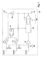
- Fig. 1 1 shows a block diagram of a push-pull bridge 100.
- the push-pull bridge 100 is part of a locating device 105 for detecting objects, in particular objects enclosed in a medium, such as a wall, a ceiling or a floor.
- the locating device - see also FIG. 5 is in particular designed as a hand-held measuring device.
- push-pull measuring bridge 100 can be used to detect a dielectric object, for example made of wood, or for detecting a metallic object, for example made of steel. In the following, the embodiment is described by means of which a dielectric object can be detected.
- a clock generator 110 has two outputs at which it provides phase-shifted, preferably 180 ° out of phase, periodic alternating signals.
- the alternating signals may in particular comprise square, triangular or sinusoidal signals.
- the outputs of the clock generator are connected to a first controllable amplifier 115 and a second controllable amplifier 120, respectively.
- Each of the controllable amplifiers 115, 120 has a control input, via which it receives a signal which controls a gain of the controllable amplifier 115, 120.
- the signals of the push-pull measuring bridge to a first electrical device 190 and / or a second electrical device 195 by means of a switch 600 (see FIG. 6 ).
- first electronic device and the second electronic device are in the FIG. 1 shown as a single unit, but with different reference numerals for the first and second device inadvertently.
- An output of the first controllable amplifier 115 is connected to a first transmitting electrode 125 and an output of the second controllable amplifier 120 is connected to a second transmitting electrode 130 of the second electronic unit 195.
- a receiving electrode 135 serves as a potential probe and is connected to an input amplifier 140; a compensation network 165 shown in the region of the electrodes 125-135 is initially not considered and an impedance 170 is omitted.
- This arrangement is referred to in the context of this application as a second electrical unit.
- the second electrical unit is, as the first electrical unit to be described - driven by the push-pull 100 - measuring bridge.
- the input amplifier 140 is shown with a constant gain factor; however, in other embodiments, an amplification factor of the input amplifier 140 may also be controllable. As a result, for example, a spatial resolution and / or sensitivity of push-pull measuring bridge 100 can be influenced and controlled, for example, as a function of a measuring signal at input amplifier 140.
- the output of the input amplifier 140 is connected to a synchronous demodulator 145.
- the synchronous demodulator 145 is further connected to the clock generator 110 connected thereto and receives from this a clock signal, which indicates the phase position of the signals provided at the outputs of the clock generator 110.
- the signals provided by the clock generator 110 are balanced square-wave signals
- one of the output signals fed to the controllable amplifiers 115, 120 can be used as a clock signal.
- the synchronous demodulator 145 alternately switches the measurement signal received from the input amplifier 140 to its upper and lower outputs based on the clock signal provided from the clock generator 110.
- the two outputs of the synchronous demodulator 145 are connected to an integrator (integrating comparator) 150, shown here as an operational amplifier connected to two resistors and two capacitors.
- integrator 150 shown here as an operational amplifier connected to two resistors and two capacitors.
- Other embodiments are also possible, for example as an active low pass.
- a digital implementation following the synchronous demodulator 145 is also conceivable, in which the signal at the outputs of the synchronous demodulator 145 is converted analog to digital at one or more times within a half-wave and then compared with the corresponding value from the next half-wave. The difference is integrated and e.g. converted back into an analog signal and used to control the amplifier 115, 120.
- the integrator 150 integrates this signal over time and provides the result at its output. While the synchronous demodulator 145 provides the measurement signal received from the input amplifier 140 at its upper output, it is integrated inversely by the integrator 150 over time and the result is provided at the output of the integrator 150.
- the voltage at the output of the integrator 150 is the integral of the difference of the low-pass filtered outputs of the synchronous demodulator 145.
- the signals provided at the outputs of the synchronous demodulator 145 have the same average over time and at the output of the integrator 150 a signal is provided goes to zero (mass).
- the capacitances are unequal, for example because a dielectric object is arranged in the region of only one of the transmitting electrodes 125, 130, then the signals provided at the outputs of the synchronous demodulator 145 are no longer equal on average, and at the output of the integrator 150 becomes a positive one or negative signal provided.
- the sign and the magnitude of the signal indicate the ratio of the capacitances, with a signal of zero corresponding to a ratio of one.
- the signal provided by the integrator 150 is provided via a connection 155 to an evaluation and output device, not shown, of the beam finder 105.
- the evaluation device can, for example, make a comparison with a threshold, so that a user of the positioning device 105 receives an optical and / or acoustic output when the signal provided by the integrator 150 exceeds a predetermined threshold. In this case, the entire signal or an amount of the signal can be compared with the threshold value.
- the signal provided by the integrator 150 is also used to control the gain factors of the controllable amplifiers 115 and 120, the second controllable amplifier 120 being directly connected to the output of the integrator 150 and the first controllable amplifier 115 being connected to the output of the integrator by means of an inverter 160 150 is connected.
- the inverter 160 effects a reversal of the signal provided to it in such a way that, as a function of the output signal of the integrator 150, the amplification factor of the first controllable amplifier 115 increases as the amplification factor of the second controllable amplifier 120 decreases or vice versa. It is also conceivable that only the amplification factor of one of the controllable amplifiers 115, 120 is controlled, while the amplification factor of the second controllable amplifier 120, 115 is kept at a fixed value.
- the amplification factors of the controllable amplifiers 115 and 120 increase or decrease until an AC component which is synchronous with the alternating voltage applied to the transmitting electrodes 125 and 130 and is applied to the receiving electrode is minimized in absolute value.
- the push-pull bridge 100 is a control circuit configured to maintain a predetermined ratio at the transmitting electrodes 125 and 130.
- the predetermined ratio is predetermined by the structure and the arrangement of the transmitting electrodes 125 and 130 to each other or to the receiving electrode 135.
- a variable ratio results from the capacitances formed at the transmitting electrodes 125 and 130 to the receiving electrode 135.
- the signal provided by integrator 150 is a control signal to compensate for asymmetric influence on the capacitances, such as through the dielectric object.
- the variable ratio at the electrodes is determined based on currents or voltages at the electrodes.
- the compensation network 165 comprises at each of the transmitting electrodes 125, 130 a voltage divider consisting of two impedances.
- the divided voltages are fed to the input amplifier 140 by means of a respective further impedance.
- the receiving electrode 135 is not directly but guided by means of the impedance 170 to the input amplifier 140.
- the illustration in FIG Fig. 1 from the compensation network 165 the impedances in the region of the first transmitting electrode 125 and the second transmitting electrode 130.
- the alternating voltages of the controllable amplifiers 115, 120 are balanced between a capacitance applied to the first (single) transmitting electrode 125 and a reference capacitance formed by the compensating network 165.
- the reference capacitance is invariant to a dielectric object. For measurement, only the first transmitting electrode 125 and the receiving electrode 135 are required.
- Compensation network 165 eliminates the impedances in the region of the second transmitting electrode 130 and the first transmitting electrode 125 is also possible.
- the push-pull bridge 100 can be used in a three-electrode measuring operation using both transmitting electrodes 125 and 130, a first two-electrode measuring operation using the first transmitting electrode 125 and the receiving electrode 135 and a second two Electrode measuring operation using the second transmitting electrode 130 and the receiving electrode 135 are operated. Switching between the different measuring operations can be cyclic or controlled by a user.
- the push-pull bridge 100 can also be used to detect a metallic object.
- a switch 600 see FIG. 6
- the voltage signals of push-pull measuring bridge 100 given to an inductive electrical device, which is referred to in this application as the first electrical unit 190.
- the push-pull measuring bridge 100 controls the first and / or the second electrical unit via the changeover switch 600. Instead of the electrodes of the second electrical E coils are used in the first electrical unit substantially. (Compare below description and explanation)
- the inductive device 190 For the description and explanation of the control of the first electrical, ie the inductive device 190 is again on FIG. 1 Referenced. In this case, the transmitting electrodes of the second electrical unit are to be replaced mentally by transmitting coils.
- the first transmitting electrode 125 is to be replaced by a first transmitting coil 175, the second transmitting electrode 130 by a second transmitting coil 180.
- the receiving electrode 135 is replaced by a single receiving coil 185 or by a system of receiving coils, preferably two receiving coils connected in series. At least one of the coils may be designed as a conductor structure on a printed circuit board ("print coil").
- the receiving electrode 135 may be formed by a single magnetoresistive magnetic field sensor, preferably a Hall effect sensor, or by a system of magnetoresistive sensors, preferably two magnetoresistive sensors connected in series Sensors, replaced.
- magnetoresistive magnetic field gradient sensors may also be used.
- the transmit coils 175, 180 generate superimposed magnetic fields with periodically varying amplitudes and phases.
- both transmit coils 175, 180 generate magnetic fields with equal amplitudes and parallel orientation of the main field directions in each half-wave of their supply voltage.
- the sign of the magnetic fields changes from half-wave to half-wave.
- the transmitting coils 175 and 180 are wound in opposite directions and their free ends connected to ground.
- the voltage supply through the controllable amplifier 115, 120 takes place with respect to ground opposite voltages.
- the transmit coils 175 and 180 in a half cycle generate magnetic fields of different amplitude and parallel or antiparallel orientation of the main field direction.
- the amplitude and the sign of the magnetic field generated by the transmitting coil 175 in a half-wave corresponds to the amplitude or the sign of the magnetic field generated by the transmitting coil 180 in the preceding or subsequent half-wave.
- the winding sense of the transmitting coils 175, 180 as well as the supply voltages of the transmitting coils 175, 180 are to be adapted accordingly to ground.
- the reception coil 185 is arranged in the region of the transmission coils 175 and 180 such that it is exposed to the superimposed magnetic field of both transmission coils 175 and 180.
- the arrangement of the coils 175 to 185 is selected such that the voltage induced in the receiving coil 185 by the magnetic fields of the transmitting coils 175 and 180 is zero, or at least constant, when the two controllable amplifiers 115 and 120 have equal amplification factors.
- the transmitting coils 175 and 180 may be coaxially arranged in two parallel planes, and the receiving coil 185 is disposed in a third parallel plane, that of the first two Each level has the same distance.
- the transmitting coils 175 and 180 may be arranged in two parallel planes.
- the two mutually connected receiving coils 185 can each be arranged in one of the two parallel planes, preferably in such a way that the orientation and position of each of the transmitting coils 175, 180 corresponds to the orientation and position of each of the receiving coils 185.
- Winding senses and interconnections of the receive coils 185 are determined from the condition that the voltage induced on the system of receive coils 185 is zero when the two controllable amplifiers 115 and 120 have equal gains. If the two transmitting coils 175, 180 in each half-wave generate magnetic fields with the same amplitude and parallel orientation of the main field direction and change the sign of the magnetic fields from half-wave to half-wave, this condition is met, for example, if the two receiving coils 185 are connected in series and wound in opposite directions. If the two receiver coils 185 are operated in antiserial series connection, then the receiver coils 185 must be wound in the same direction.
- the transmitting coils 175 and 180 are located at at least slightly axially or laterally staggered positions such that a metallic article generally occupies different distances from the transmitting coils 175 and 180.
- a stay of the object in a plane between the transmitting coils 175 and 180, in which the object in the case of axially offset transmitting coils 175, 180 equidistant from the transmitting coils 175 and 180, can be avoided by the arrangement of the transmitting coils 175 and 180 in the locating device 105 , Due to the asymmetrical position of the object with respect to the transmitting coils 175 and 180, the object is influenced differently by the magnetic fields of the transmitting coils 175 and 180.
- the magnetic fields are also through influences the metallic article differently so that the voltage induced by the superimposed magnetic fields in the receiving coil 185 is no longer zero.
- the push-pull bridge 100 compensates for this asymmetry by driving one of the amplifiers 115 and 120 to a higher amplification factor than the other of the amplifiers 115, 120 until the voltage induced by the superimposed magnetic fields in the receiver coil 185 is restored has reached zero.
- the variable ratio between the transmitting coils 175 and 180 then no longer corresponds to 1 and the terminal 155 is at a non-zero voltage. By comparing the voltage applied to the terminal 155 with the predetermined value zero (corresponding to the predetermined ratio one), the metallic object can be detected.
- FIG. 6 the schematic structure of the locating device according to the invention is shown in a preferred embodiment.
- the device has at least one push-pull bridge 100 - as described.
- a first electrical device 190 and a second electrical device 195 are provided, which can be acted upon by a change-over switch 600 of the push-pull measuring bridge 100. It is thus possible to operate two electrical devices, ie two sensors, with (only) one push-pull measuring bridge.
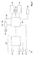
- Fig. 2 shows a schematic representation of the locating device 105 with the push-pull bridge 100 from Fig. 1 .
- the push-pull bridge 100 is advantageously integrated in an IC, for example an ASIC (application-specific IC).
- the locating device 105 comprises a processing device 205, which is connected to the push-pull measuring bridge 100. Furthermore, the processing device 205 is connected to a voltage sensor 210 and a power controller 215, which in turn is connected to a battery 220, for example a rechargeable battery and a charging socket 225. In addition, the processing device 205 is connected to a data interface 230, an optical output device 235, an acoustic output device 240, an input device 245 and a position sensor 250.
- push-pull bridge 100 is constructed separately from processing device 205.
- elements of push-pull bridge 100 may also be processed by the processing device 205 be formed.
- the switch between the first electrical device and the second electrical device may be part of the processing device 205.
- the processing device 205 is preferably a conventional digital microcomputer with a power clock generator and program and data storage.
- DAC digital-to-analog converters
- ADC analog-to-digital converter
- the processing means 205 may implement the clock generator 110, the controllable amplifiers 115 and 120, the synchronous demodulator 145, the integrator 150 and / or the inverter 160.
- the evaluation of the signal provided at the terminal 155 of the push-pull measuring bridge 105 can also take place by means of the processing device 205. This includes comparing the signal with a predetermined value and determining whether the difference between the signal and the predetermined value exceeds a predetermined level.
- the functionalities described can also be implemented by discrete components, for example by analog electronic circuits or in the form of a user-specific IC (ASIC).
- the voltage sensor 210 is a known sensor that detects an electromagnetic field generated by a live or live conductor. In one embodiment, only alternating electromagnetic fields of a predetermined frequency range are detected by the voltage sensor 210, for example in the frequency range above 20 Hz, preferably in a range of approximately 45 to 65 Hz. More preferably, the voltage sensor 210 determines the electromagnetic field due to the electrical Field applied to a measuring electrode of the voltage sensor 210 electrical voltage.
- auxiliary sensors may be connected to the processing device 210 for improving a measurement result of the push-pull measuring bridge 100.
- auxiliary sensors may be connected to the processing device 210 for improving a measurement result of the push-pull measuring bridge 100.
- sensors include, for example, a sensor which determines whether the electromagnetic devices 190 to 198 are aligned in a required manner with respect to a measuring surface, in particular, whether distances between the measuring surface and the electromagnetic devices 190 to 198 are the same. A tilting of the locating device 105 with respect to the measuring surface can be prevented.
- the measuring surface is usually the surface of a body in which the object to be detected is received.
- the body can be a wall or wall and the object hidden in it.
- the power controller 215 provides the locator 105 with voltages required for operation.
- the electrical energy required for this purpose is taken from the battery 220, for example a rechargeable battery.
- the power controller 215 may be supplied with electrical power via the charging socket 225, the power controller 215 controlling and monitoring the charging of the battery 220. Operation of the locator 105 based on electrical energy supplied exclusively via the charging socket 225 is also possible.
- the charging socket 225 is usually a low-voltage plug whose counterpart is connected to a power supply unit.
- a charging station may be provided into which the locator 105 is inserted, with the charging socket 225 electrically connected to the power supply so that the battery 220 can be charged.
- the power supply can also be included in the locating device 105 and the charging socket 225 can be connected to the usual power grid.
- Portions of the logic for powering the locator 105 and for controlling the charging of the battery 220 may be implemented by the processor 205. Further, the processing means 205 may act on the power controller 215, for example in the form of an automatic shutdown of the locator 105 after a predetermined time in which the locator 105 has not been used, or in the form of a query of a current state of charge of the battery 220.
- the processing device 205 can exchange information with an external device. Such information may relate to measurement results that have been collected or stored in a memory of the processing device 205.
- the data interface 230 and the charging socket 225 can be designed to be integrated with each other.
- the data interface 230 is a digital serial data interface, in particular a USB interface.
- the optical output device 235 comprises a number of light-emitting diodes for visualizing a measurement result of the push-pull measuring bridge 100. Further light-emitting diodes for displaying internal states of the locating device 105 can also be included, for example for indicating a state of charge of the battery.
- the optical display device 235 comprises a graphic display, such as a liquid crystal display (LCD).
- the LCD may include a backlight, such as LED or OLED, and may include a dot matrix area on which individual dots may be selectively displayed.
- Both the LCD and the backlight or light emitting diodes of the first embodiment may support multiple output colors.
- the optical output device is designed such that operation of the locating device 105 is possible both in a light and in a dark environment. For this purpose, a luminous intensity of the LED or the backlight of the LCD can be adapted to the lighting conditions in the environment.
- the acoustic output device 240 may include a speaker or a piezo-transducer.
- the representation of a measurement result of the push-pull measuring bridge 100 can be emitted visually and acoustically by means of the optical output device 235 and the acoustic output device 240 optically, acoustically or in combination.
- a position of a detected object may be displayed on the optical output device 235, while a characteristic noise from the acoustic output device 240 indicates a metallic property of the article.
- a color of the optically represented object can be symbolized at a distance, in particular a depth of the object. Associations between the color and the sound to properties of the article (metallic, dielectric, live) may be changeable, in one embodiment also by a user of the locator 105.
- the input device 245 may include a number of keys that may be combined in a keyboard. In one embodiment, the Input device 245 only a single button, with a complete operability of the locating device 105 is ensured by means of this one button.
- the input device 245 may be partially or fully backlit.
- the backlight may be coupled to a backlight of the optical output device 235. Alternatively or additionally, the backlight may be user controlled.
- the input device 245 may comprise further input means, in particular a rotary or slide controller. Such a controller may be sampled analog or digital and in particular serve for stepless or finely granular change of a parameter of the locating device 105. By means of such a regulator, a sensitivity of the push-pull measuring bridge 100 can be adjustable.
- the input device 245 may be implemented in whole or in part with the optical output device 235 in the form of a touch-sensitive screen ("touchscreen").
- the position sensor 250 serves to determine a position of the locating device 105 with respect to the measuring surface by detecting a displacement of the locating device 105 with respect to the measuring surface.
- the detection can be one-dimensional or two-dimensional.
- an acceleration sensor preferably a micromechanical acceleration sensor
- an impeller may be arranged in the region between the locating device 105 and the measuring surface, wherein a rotation of the impeller by the processing device 205 is converted into a displacement.
- a mechanism similar to that in a computer mouse may be used by holding a trackball between the locator 105 and the measurement surface, and scanning a displacement of the locator 105 based on movement of the trackball in two dimensions.
- an optical scan similar to an optical computer mouse may be performed, wherein the position sensor 250 comprises a camera facing the measurement surface, and the position sensor 250 translates the image captured by the camera into a displacement of the locator 105 the measuring surface converted.
- the conversion can also be carried out by the processing device 205.
- a light source for example in the form of one or more light-emitting diodes, can be arranged.
- push-pull measuring bridge 100 may also be included in the locating device 105 and connected to the processing device 205.
- different electromagnetic devices 190 to 198 controlled by the processing device 205, can be connectable to the one or more push-pull measuring bridges 100 so that measurements can be carried out by means of differently designed or situated electromagnetic devices 190 to 198.
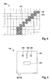
- Fig. 3 shows different arrangements of the electromagnetic devices 190 to 198 for a push-pull bridge 100 from Fig. 1
- Fig. 3A shows a matrix-like arrangement.
- the third electromagnetic element 198 forms the middle element of a 3x3 matrix whose remaining elements are formed by first and second electromagnetic devices 190, 195.
- a first electromagnetic element 190 and a second electromagnetic element 195 are opposite each other.
- Fig. 3B shows a honeycomb arrangement of electromagnetic devices 190 to 198.
- the third electromagnetic device 198 six instead of eight adjacent electromagnetic devices 190, 195 on.
- the electromagnetic devices 190, 195 comprise coils
- the in Fig. 3B shown embodiment since the coils better to the honeycomb shape than the rectangular shape in Fig. 3A approximate.
- a surface packing density of the electromagnetic devices 190 to 198 may be increased in a honeycomb arrangement.
- FIGS. 3A and 3B arrangements shown can be continued in any direction in the drawing plane.
- an arbitrarily large arrangement of electromagnetic devices 190 to 198 can in principle be supported.
- a plurality of push-pull measuring bridges 100 are provided in the locating device 105, it is also possible to carry out a plurality of measurements at the same time, it being necessary to ensure a sufficient distance between active electromagnetic devices 190 to 198 in order to avoid mutual interference.
- the electromagnetic devices 190 to 198 involved in a measurement need not adjoin one another but can be separated from one another by further, preferably non-interconnected, electromagnetic devices 190 to 198.
- FIGS. 3A and 3B shown arrangements are connected in a corresponding manner.
- Fig. 3C shows an exemplary embodiment of a combined measuring element 310 for the first and the second electrical unit.
- the combined measuring element 310 comprises a circular disk-shaped electrode 125 to 135, which is surrounded by a round coil 175 to 185. Centers of the electrodes 125-135 and the coils 175-185 coincide to detect objects having different characteristics (metallic, dielectric) with respect to the same position.
- the measuring element 310 can in the in the FIGS. 3A and 3B shown arrangements are used.
- the voltage sensor 210 may be implemented with one of the electromagnetic devices 190 to 198 integrated.
- the voltage sensor can also be arranged on a side of the electromagnetic devices 190 to 198 facing away from the measuring surface.
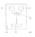
- Fig. 4 shows a visualization of a graphical display of the locator 105 from Fig. 2
- a graphical output 410 is divided into a number of display areas 420, 430 in a matrix-like manner.
- the display areas 420 are bright, the display areas 430 are colored dark.
- the dark colored display areas 430 represent positions where the object was detected. Instead of a subdivision into dark and light, it is also possible to use a greyscale or false color representation, wherein the gray level or color shown signals a removal of the object or a property of the object (metallic, dielectric, live).
- Each of the display areas 420, 430 corresponds to a third electromagnetic device 198 in a matrix-like arrangement as in FIG Fig. 3A ,
- the output 410 gives a visual impression of a size and location of the object to be detected.
- Fig. 4 symbolically, there are further display regions 420, 430 outside the output 410. These represent measurement results which were carried out and stored at different positions by means of the locating device 105. By moving the measuring device 105 on the measuring surface, the detail displayed on the output 410 can be shifted over these stored measured values. Different graphical processing of the stored measured values can be carried out.
- the measured values may each represent the variable ratio and a comparison with the predetermined ratio and a corresponding representation on the output 410 in light or dark can be performed "fresh" for the display areas 420, 430 in the area of the output 410.
- the predetermined ratio can be adjusted according to a user input.
- a bar graph may appear, wherein the length of a bar may correspond to a value of the variable ratio or its deviation from the predetermined ratio.
- This type of representation is particularly suitable for a one-dimensional displacement of the locating device 105 with respect to the measuring surface. Saved display areas 420, 430 beyond the output 410 then exist only in one area direction, ie either horizontally or vertically. If the locating device 105 is vertically displaceable, then the bars are preferably shown horizontally and vice versa.
- Fig. 5 shows a view of an exemplary locating device 105.
- the locating device 105 includes an input device and an optical output device in the form of a display.
- the locating device 105 is accommodated in a housing 510.
- a handle is arranged, which, however, can also be formed on the top of the device.
- the locator 105 may be sealed to 1P54 standard.
- the representation of the measurement results i. the signaling of the detection of found objects can be visualized, for example, via a segment or dot-matrix display.
- the optical display device 235 comprises a graphic display, such as a liquid crystal display (LCD).
- the LCD may include a backlight, such as LED or OLED, and may include a dot matrix area on which individual dots may be selectively displayed.
- Both the LCD and the backlight or light emitting diodes of the first embodiment may support multiple output colors.
- the optical output device is designed such that operation of the locating device 105 is possible both in a light and in a dark environment. For this purpose, a luminous intensity of the LED or the backlight of the LCD can be adapted to the lighting conditions in the environment.
- a button 245 controls all the functions of the locating device 105. In the simplest case, only switching on and off of the locating device 105 is controlled by means of the button 245. By longer or shorter, simple and multiple keystrokes on the button 245, other functions of the locator 105 may be controlled, such as switching a sensitivity, a calibration or an output of the state of charge of the battery 220th
- buttons for example, selection buttons, whether to be measured with the first or the second electrical unit.
- the device according to the invention also has a device-internal power supply, which may be formed by batteries or even rechargeable batteries.
- the batteries can be permanently integrated in the device or can also be removed from the device for charging purposes.
- the charging electronics is integrated in the device.
- the supply of external energy is then via an interface to the housing of the device, such as a low-voltage connector or a USB socket
- a USB socket may be present as a combined data interface 230 and charging socket 225, as shown in FIG FIG. 6 is shown.
- the output unit can also enable the display of measurement results via LEDs.
- the thresholds of the individual LEDs can be generated by a controller integrated in the device or by analogue electronics. In this case, e.g. the center finding can be visualized via colored LEDs or an AC line can also be displayed.
- the LEDs 235 in the embodiment of FIG. 5 indicate a position of the object to the left or right of a center mark 520 on the housing 510.
- Non-visible electromagnetic devices 190 to 198 are centered with respect to the center mark 520. If both light-emitting diodes 235 are equally bright, then the object is located uniformly below the center mark 520. In order to find an edge of the object, the positioning device 105 must be displaced until the light-emitting diodes 235 shine differently brightly. Ideally, the edge of the object is just below the Center mark 520 when one LED 235 is turned off and the other LED 235 has reached maximum brightness.
- the optical display device 235 may be a graphic display, such as a liquid crystal display (LCD).
- the LCD may include a backlight, such as LED or OLED, and may include a dot matrix area on which individual dots may be selectively displayed.
- Both the LCD and the backlight or light emitting diodes of the first embodiment may support multiple output colors.
- the optical output device is designed such that operation of the locating device 105 is possible both in a light and in a dark environment. For this purpose, a luminous intensity of the LED or the backlight of the LCD can be adapted to the lighting conditions in the environment.
- the locating device may also have an acoustic transmitter.
- This may be, for example, a loudspeaker or a piezo converter, with which, for example, the detection of an AC line can be signaled.
- the acoustic generator can be operated via a controller (or an analog threshold-generating electronics) depending on the signal strength of the measuring system with different frequencies / rhythms, thus signaling an object detection and differentiation.
- the locating device may have a mechanical or optical displacement transmitter.
- Mechanical displacement sensors wheels with light barrier and segment disc
- optical displacement sensors such as optical mouse sensors
- acceleration sensors record the distance that the hand-held locating device is moved over a surface. This information is provided to signal processing, e.g. to improve the sensor performance or display.
- the detection data can thus also be assigned to specific location positions of the device.
- the electronics arranged in the housing of the device advantageously have at least one controller, with which the measuring method described here and the Functions of the device, as partially executed, can be controlled.
- the controller can control a variety of functions, such as an NMI interface, a charging electronics control or regulation or even an "auto-off function" or cover.
- the function of the controller, in particular for the housing functions can also be covered by analogue electronics.
Landscapes
- Physics & Mathematics (AREA)
- Engineering & Computer Science (AREA)
- Remote Sensing (AREA)
- Life Sciences & Earth Sciences (AREA)
- General Physics & Mathematics (AREA)
- Electromagnetism (AREA)
- Environmental & Geological Engineering (AREA)
- Geology (AREA)
- General Life Sciences & Earth Sciences (AREA)
- Geophysics (AREA)
- Measurement Of Length, Angles, Or The Like Using Electric Or Magnetic Means (AREA)
- Geophysics And Detection Of Objects (AREA)
Priority Applications (5)
| Application Number | Priority Date | Filing Date | Title |
|---|---|---|---|
| EP11188062.1A EP2589987A1 (de) | 2011-11-07 | 2011-11-07 | Ortungsgerät |
| US13/670,212 US8860435B2 (en) | 2011-11-07 | 2012-11-06 | Locating appliance |
| RU2012147004/28A RU2012147004A (ru) | 2011-11-07 | 2012-11-06 | Детектор для обнаружения и определения положения скрытых объектов |
| CN201210437577.XA CN103091716B (zh) | 2011-11-07 | 2012-11-06 | 定位设备 |
| JP2012245657A JP6202803B2 (ja) | 2011-11-07 | 2012-11-07 | 位置測定装置 |
Applications Claiming Priority (1)
| Application Number | Priority Date | Filing Date | Title |
|---|---|---|---|
| EP11188062.1A EP2589987A1 (de) | 2011-11-07 | 2011-11-07 | Ortungsgerät |
Publications (1)
| Publication Number | Publication Date |
|---|---|
| EP2589987A1 true EP2589987A1 (de) | 2013-05-08 |
Family
ID=44992647
Family Applications (1)
| Application Number | Title | Priority Date | Filing Date |
|---|---|---|---|
| EP11188062.1A Withdrawn EP2589987A1 (de) | 2011-11-07 | 2011-11-07 | Ortungsgerät |
Country Status (5)
| Country | Link |
|---|---|
| US (1) | US8860435B2 (zh) |
| EP (1) | EP2589987A1 (zh) |
| JP (1) | JP6202803B2 (zh) |
| CN (1) | CN103091716B (zh) |
| RU (1) | RU2012147004A (zh) |
Cited By (2)
| Publication number | Priority date | Publication date | Assignee | Title |
|---|---|---|---|---|
| WO2013185948A1 (de) * | 2012-06-14 | 2013-12-19 | Robert Bosch Gmbh | Balkendetektor mit regelschaltung |
| WO2014191351A3 (de) * | 2013-05-27 | 2015-02-19 | iCONTROLS k.s. | Induktiver sensor |
Citations (10)
| Publication number | Priority date | Publication date | Assignee | Title |
|---|---|---|---|---|
| US4859931A (en) * | 1986-12-23 | 1989-08-22 | Matsushita Electric Works, Ltd. | Electronic detector with capacitor sensor and magnetic field sensor for locating an object behind a wall surface |
| DE4141264C1 (en) * | 1991-12-14 | 1993-03-18 | Werner Turck Gmbh & Co Kg, 5884 Halver, De | Inductive proximity sensor - has oscillator in bridge circuit in branch of current source and continuously restores bridge balance |
| US6211662B1 (en) * | 1998-08-07 | 2001-04-03 | The Stanley Works | Hand-held hidden object sensor for sensing a location of objects hidden behind a surface of an architectural structure |
| US20030006761A1 (en) * | 2001-06-01 | 2003-01-09 | Naruaki Hiramatsu | Contact displacement detector and sensor |
| JP2005210146A (ja) * | 2003-01-09 | 2005-08-04 | Kura Gijutsu Kenkyusho:Kk | 二つの回路素子の微小差検出回路及びそれを用いた位置検出装置,磁性体或いは導体の欠陥或いは有無の識別検査装置 |
| DE102008005783A1 (de) | 2008-01-23 | 2009-07-30 | Gerd Reime | Feuchteunabhängiger kapazitiver Einklemmschutz |
| CN101943759A (zh) * | 2009-07-10 | 2011-01-12 | 嘉纳尔科技(北京)有限公司 | 一种非接触式物体探测用传感器 |
| DE102010028723A1 (de) | 2010-05-07 | 2011-11-10 | Robert Bosch Gmbh | Erfassung eines metallischen oder magnetischen Objekts |
| DE102010031147A1 (de) | 2010-05-07 | 2011-11-10 | Robert Bosch Gmbh | Erfassung eines metallischen oder magnetischen Objekts |
| DE102010028718A1 (de) | 2010-05-07 | 2011-11-10 | Robert Bosch Gmbh | Erfassung eines dielektrischen Objekts |
Family Cites Families (3)
| Publication number | Priority date | Publication date | Assignee | Title |
|---|---|---|---|---|
| JP2681040B2 (ja) * | 1987-03-16 | 1997-11-19 | 株式会社マイゾックス | 非金属・金属部材探知器 |
| JP2004184286A (ja) * | 2002-12-04 | 2004-07-02 | Matsushita Electric Works Ltd | 背後部材検知装置 |
| JP2004184257A (ja) * | 2002-12-04 | 2004-07-02 | Kura Gijutsu Kenkyusho:Kk | 二組の抵抗或いはコイル或いはコンデンサの微小差検出回路及びそれを用いた位置検出装置及び導体の欠陥或いは有無の識別検査装置 |
-
2011
- 2011-11-07 EP EP11188062.1A patent/EP2589987A1/de not_active Withdrawn
-
2012
- 2012-11-06 RU RU2012147004/28A patent/RU2012147004A/ru not_active Application Discontinuation
- 2012-11-06 US US13/670,212 patent/US8860435B2/en active Active
- 2012-11-06 CN CN201210437577.XA patent/CN103091716B/zh not_active Expired - Fee Related
- 2012-11-07 JP JP2012245657A patent/JP6202803B2/ja not_active Expired - Fee Related
Patent Citations (10)
| Publication number | Priority date | Publication date | Assignee | Title |
|---|---|---|---|---|
| US4859931A (en) * | 1986-12-23 | 1989-08-22 | Matsushita Electric Works, Ltd. | Electronic detector with capacitor sensor and magnetic field sensor for locating an object behind a wall surface |
| DE4141264C1 (en) * | 1991-12-14 | 1993-03-18 | Werner Turck Gmbh & Co Kg, 5884 Halver, De | Inductive proximity sensor - has oscillator in bridge circuit in branch of current source and continuously restores bridge balance |
| US6211662B1 (en) * | 1998-08-07 | 2001-04-03 | The Stanley Works | Hand-held hidden object sensor for sensing a location of objects hidden behind a surface of an architectural structure |
| US20030006761A1 (en) * | 2001-06-01 | 2003-01-09 | Naruaki Hiramatsu | Contact displacement detector and sensor |
| JP2005210146A (ja) * | 2003-01-09 | 2005-08-04 | Kura Gijutsu Kenkyusho:Kk | 二つの回路素子の微小差検出回路及びそれを用いた位置検出装置,磁性体或いは導体の欠陥或いは有無の識別検査装置 |
| DE102008005783A1 (de) | 2008-01-23 | 2009-07-30 | Gerd Reime | Feuchteunabhängiger kapazitiver Einklemmschutz |
| CN101943759A (zh) * | 2009-07-10 | 2011-01-12 | 嘉纳尔科技(北京)有限公司 | 一种非接触式物体探测用传感器 |
| DE102010028723A1 (de) | 2010-05-07 | 2011-11-10 | Robert Bosch Gmbh | Erfassung eines metallischen oder magnetischen Objekts |
| DE102010031147A1 (de) | 2010-05-07 | 2011-11-10 | Robert Bosch Gmbh | Erfassung eines metallischen oder magnetischen Objekts |
| DE102010028718A1 (de) | 2010-05-07 | 2011-11-10 | Robert Bosch Gmbh | Erfassung eines dielektrischen Objekts |
Cited By (4)
| Publication number | Priority date | Publication date | Assignee | Title |
|---|---|---|---|---|
| WO2013185948A1 (de) * | 2012-06-14 | 2013-12-19 | Robert Bosch Gmbh | Balkendetektor mit regelschaltung |
| RU2625440C2 (ru) * | 2012-06-14 | 2017-07-13 | Роберт Бош Гмбх | Детектор элементов каркаса со схемой регулирования |
| US9772421B2 (en) | 2012-06-14 | 2017-09-26 | Robert Bosch Gmbh | Beam detector with control circuit |
| WO2014191351A3 (de) * | 2013-05-27 | 2015-02-19 | iCONTROLS k.s. | Induktiver sensor |
Also Published As
| Publication number | Publication date |
|---|---|
| CN103091716A (zh) | 2013-05-08 |
| CN103091716B (zh) | 2017-06-13 |
| US20130120004A1 (en) | 2013-05-16 |
| JP6202803B2 (ja) | 2017-09-27 |
| US8860435B2 (en) | 2014-10-14 |
| RU2012147004A (ru) | 2014-05-20 |
| JP2013101121A (ja) | 2013-05-23 |
Similar Documents
| Publication | Publication Date | Title |
|---|---|---|
| EP2567460A1 (de) | Suchgerät | |
| EP2567265B1 (de) | Erfassung eines metallischen oder magnetischen objekts | |
| DE102009057439B4 (de) | Vorrichtung und Verfahren zur fehlerfreien kapazitiven Messwerterfassung | |
| EP2567262B1 (de) | Erfassung eines metallischen oder magnetischen objekts | |
| EP1728102A1 (de) | Ortungsgerät mit ausgabeeinheit zur widergabe einer ausgabegrösse | |
| EP2567459B1 (de) | Erfassung eines dielektrischen objekts | |
| DE102019209474A1 (de) | Skalierungskonfiguration für induktiven Positionscodierer | |
| DE3722890A1 (de) | Manuell zu betaetigender positionsgeber | |
| DE102010039946A1 (de) | Messvorrichtung, insbesondere Messvorrichtung zur Erfassung metallischer Gegenstände | |
| DE102015117067B4 (de) | Integrierte Schaltungsanordnung für einen Positionssensor | |
| WO2013013896A2 (de) | Suchgerät | |
| EP2567263B1 (de) | Erfassung eines metallischen oder magnetischen objekts | |
| EP2589987A1 (de) | Ortungsgerät | |
| DE102013226203A1 (de) | Offsetkompensierte Positionsmessvorrichtung | |
| CN1057830C (zh) | 用于借助电容检测来确定物体的相应几何位置的方法和装置 | |
| EP1613939B1 (de) | Anordnung und verfahren zur bestimmung von temperaturen | |
| DE102006012952B4 (de) | Vorrichtung und Verfahren zur Positionsbestimmung | |
| DE102005025588B4 (de) | Anordnung zur Positionsmessung bei einer magnetisch gelagerten Welle | |
| DE102012210004B4 (de) | Balkendetektor mit Regelschaltung | |
| EP2388623B1 (de) | Kapazitivsensor | |
| DE102023120323A1 (de) | Induktiver positionscodierer, der ein geneigtes skalenmuster nutzt | |
| WO2017060414A1 (de) | Energieersparnis bei einem zeigeinstrument für kapazitive sensoroberflächen durch zeitliche modulation | |
| DE102015219484A1 (de) | Energieersparnis bei einem Zeigeinstrument für kapazitive Sensoroberflächen durch zeitliche Modulation |
Legal Events
| Date | Code | Title | Description |
|---|---|---|---|
| PUAI | Public reference made under article 153(3) epc to a published international application that has entered the european phase |
Free format text: ORIGINAL CODE: 0009012 |
|
| AK | Designated contracting states |
Kind code of ref document: A1 Designated state(s): AL AT BE BG CH CY CZ DE DK EE ES FI FR GB GR HR HU IE IS IT LI LT LU LV MC MK MT NL NO PL PT RO RS SE SI SK SM TR |
|
| AX | Request for extension of the european patent |
Extension state: BA ME |
|
| 17P | Request for examination filed |
Effective date: 20131108 |
|
| RBV | Designated contracting states (corrected) |
Designated state(s): AL AT BE BG CH CY CZ DE DK EE ES FI FR GB GR HR HU IE IS IT LI LT LU LV MC MK MT NL NO PL PT RO RS SE SI SK SM TR |
|
| 17Q | First examination report despatched |
Effective date: 20180720 |
|
| RAP1 | Party data changed (applicant data changed or rights of an application transferred) |
Owner name: ROBERT BOSCH GMBH |
|
| STAA | Information on the status of an ep patent application or granted ep patent |
Free format text: STATUS: THE APPLICATION IS DEEMED TO BE WITHDRAWN |
|
| 18D | Application deemed to be withdrawn |
Effective date: 20200103 |