EP2589941A2 - Method and device for compensating for the temperature of at least one temperature-dependent parameter - Google Patents
Method and device for compensating for the temperature of at least one temperature-dependent parameter Download PDFInfo
- Publication number
- EP2589941A2 EP2589941A2 EP12176513.5A EP12176513A EP2589941A2 EP 2589941 A2 EP2589941 A2 EP 2589941A2 EP 12176513 A EP12176513 A EP 12176513A EP 2589941 A2 EP2589941 A2 EP 2589941A2
- Authority
- EP
- European Patent Office
- Prior art keywords
- temperature
- sensor
- measured
- determined
- measured variable
- Prior art date
- Legal status (The legal status is an assumption and is not a legal conclusion. Google has not performed a legal analysis and makes no representation as to the accuracy of the status listed.)
- Granted
Links
- 230000001419 dependent effect Effects 0.000 title claims abstract description 42
- 238000000034 method Methods 0.000 title claims abstract description 30
- 230000008859 change Effects 0.000 claims abstract description 38
- 238000005259 measurement Methods 0.000 claims abstract description 36
- 230000002123 temporal effect Effects 0.000 claims abstract description 13
- 238000011156 evaluation Methods 0.000 claims description 24
- 230000006399 behavior Effects 0.000 claims description 16
- BASFCYQUMIYNBI-UHFFFAOYSA-N platinum Chemical compound [Pt] BASFCYQUMIYNBI-UHFFFAOYSA-N 0.000 claims 4
- 229910052697 platinum Inorganic materials 0.000 claims 2
- 238000010586 diagram Methods 0.000 description 4
- 238000010438 heat treatment Methods 0.000 description 3
- 230000004913 activation Effects 0.000 description 2
- 230000005494 condensation Effects 0.000 description 2
- 238000009833 condensation Methods 0.000 description 2
- 230000006870 function Effects 0.000 description 2
- 238000012886 linear function Methods 0.000 description 2
- 239000000463 material Substances 0.000 description 2
- 239000000956 alloy Substances 0.000 description 1
- 229910045601 alloy Inorganic materials 0.000 description 1
- 230000008901 benefit Effects 0.000 description 1
- 238000004364 calculation method Methods 0.000 description 1
- 230000007423 decrease Effects 0.000 description 1
- 230000000694 effects Effects 0.000 description 1
- 238000009434 installation Methods 0.000 description 1
- 238000007620 mathematical function Methods 0.000 description 1
- 230000008569 process Effects 0.000 description 1
- 230000005855 radiation Effects 0.000 description 1
- 238000009423 ventilation Methods 0.000 description 1
- 238000010792 warming Methods 0.000 description 1
Images

Classifications
-
- G—PHYSICS
- G01—MEASURING; TESTING
- G01D—MEASURING NOT SPECIALLY ADAPTED FOR A SPECIFIC VARIABLE; ARRANGEMENTS FOR MEASURING TWO OR MORE VARIABLES NOT COVERED IN A SINGLE OTHER SUBCLASS; TARIFF METERING APPARATUS; MEASURING OR TESTING NOT OTHERWISE PROVIDED FOR
- G01D3/00—Indicating or recording apparatus with provision for the special purposes referred to in the subgroups
- G01D3/028—Indicating or recording apparatus with provision for the special purposes referred to in the subgroups mitigating undesired influences, e.g. temperature, pressure
-
- G—PHYSICS
- G01—MEASURING; TESTING
- G01K—MEASURING TEMPERATURE; MEASURING QUANTITY OF HEAT; THERMALLY-SENSITIVE ELEMENTS NOT OTHERWISE PROVIDED FOR
- G01K1/00—Details of thermometers not specially adapted for particular types of thermometer
- G01K1/20—Compensating for effects of temperature changes other than those to be measured, e.g. changes in ambient temperature
Definitions
- the invention relates to a method for temperature compensation of at least one temperature-dependent measured variable referred to in the preamble of claim 1, and a corresponding device for temperature compensation of at least one temperature-dependent measurement of the type mentioned in the preamble of claim 7.
- Methods for temperature compensation of at least one temperature-dependent measured variable such as, for example, a humidity and / or temperature on or on a windshield, are known from the prior art.
- a measuring device is usually mounted in the area of the windshield and as a rule comprises a plurality of sensors for detecting the measured variables and an evaluation and control unit for evaluating the sensor data.
- a relative humidity precipitated on a disk is measured by a humidity sensor as a relative humidity. Furthermore, a moisture signal corresponding to the measured moisture is fed to an evaluation and control unit which, for example, activates a ventilation system.
- the evaluation and control unit is supplied with a signal of a solar sensor, which corresponds to the intensity of the incident solar radiation. From this signal, the heating of the humidity sensor is determined. From the warming and The measured relative humidity then determines the actual relative humidity at the disk surface.
- the described device for measuring the relative humidity and for calibration of the humidity sensor comprises a fog sensor for detecting condensed air humidity, a temperature sensor for measuring the temperature at a condensation surface, a humidity sensor for measuring a relative humidity in the interior of the vehicle, an air temperature sensor for measuring the air temperature and an evaluation and control unit, which receives and evaluates the signals of all sensors.
- the evaluation and scattering unit assigns the output signal of the humidity sensor, which results from the detected condensed air humidity, to the relative air humidity, which results arithmetically from the output signals of the condensation surface temperature sensor and the air temperature sensor present in this state.
- the object of the invention is to specify a method for temperature compensation of at least one temperature-dependent measured variable and a device for temperature compensation of at least one temperature-dependent measured variable, which allow a precise determination of the at least one temperature-dependent measured variable in a closed measuring environment by taking into account internal disturbances.
- the advantage achieved with the invention is that internal temperature disturbances and their temporal courses are determined and stored and can then be taken into account as known quantities in the determination of at least one temperature-compensated measured variable.
- This advantageously enables a more accurate determination of the at least one temperature-dependent measured variable, in particular when the sensor unit is self-heating and / or when the measuring environment is heated.
- the unwanted heating can be caused by the measuring process itself and / or by a heat-generating component in the measuring environment.
- the state of the heat-generating component can be taken into account, wherein the component generates and releases heat in an active state and generates no heat in a non-active state, but under certain circumstances can still emit residual heat.
- By determining the temporal course of the temperature behavior possibly existing warm-up and cool-down phases for the temperature compensation can be taken into account in an advantageous manner.
- the basic idea of the invention is based on the fact that the temporal temperature behavior of a component causing the unwanted temperature change, which is arranged within the closed measuring environment, can be determined and stored, the at least one measured temperature-dependent measured variable for outputting at least one corresponding temperature-compensated measured variable in accordance with the invention determined temporal temperature behavior of the component can be mathematically corrected.
- the temperature change of the measuring environment and / or a sensor arranged in the measuring environment can be calculated from the temporal temperature behavior of the component, wherein the at least a measured temperature-dependent measured variable is mathematically corrected by the temperature change.
- the change in temperature of the sensor or of the measuring environment can be determined in an uncomplicated manner advantageously by a temperature sensor or calculated mathematically in the case of known material properties.
- a mathematical compensation of the temperament-dependent measured variable can advantageously be calculated by replacing the measured temperature value with the temperature value corrected via the temperature change.
- a board temperature can be measured.
- the at least one temperature-dependent measured measured variable and / or the at least one temperature-compensated measured variable can be mathematically corrected by the difference between the measured board temperature and the measuring ambient temperature. In this way, further disturbances, which can lead to the falsification of the measurement result, can be excluded.
- the measured board temperature can be stored, wherein from the currently determined board temperature and a previously determined and stored board temperature, the temperature change between the two measurement times can be calculated.
- the temperature change for temperature compensation can be advantageously determined directly, and errors can be avoided in an advantageous manner, which can occur in a mathematical approximation.
- At least one further variable preferably a relative humidity and / or a fogging probability for a windshield
- at least one further variable can be determined from the at least one temperature-compensated measured variable.
- the context between the relative humidity and the humidity change over the temperature are described as a linear function.
- the relationship between the temperature change and the humidity change can be described by a linear function.
- the temperature-compensated relative humidity can be calculated advantageously via simple mathematical functions.
- raindrops and / or light and / or moisture and / or temperature can be determined and / or detected and / or corrected and / or compensated on or on a windshield via at least one sensor, wherein the corresponding sensors can be activated independently.
- the corresponding sensors can be activated independently.
- windscreen wipers and / or a fan blower and / or lighting functions such as low beam, high beam, rear fog light, fog light, etc. can be activated.
- measurement results which are falsified by the operation of another sensor can be advantageously corrected by the described method.
- a rain sensor can cause an increase in the temperature of the windshield in the measurement environment due to the use of an infrared light-emitting diode arrangement. Due to the increased temperature in the measurement environment, the humidity sensor measures a lower humidity value. This measured moisture value does not match the value of moisture in the other areas of the windshield outside the measurement environment. Due to the known temperature profile of the activated rain sensor, the temperature increase in the measuring environment can be determined and the measured moisture value can be corrected. As a result, for example, a risk of misting the windshield can be determined correctly and output to the blower control.
- the device according to the invention for temperature compensation of at least one temperature-dependent measured variable which is measured by a sensor integrated in a sensor unit in a measuring environment of an object, comprises an evaluation and control unit, wherein an undesired temperature change falsifies the at least one measured result measured in the measuring environment.
- the temporal temperature behavior of a component which is arranged within the closed measuring environment and causes the unintentional temperature change of the measurement environment, deposited as at least one characteristic in a memory unit
- the evaluation and control unit corrects the at least one temperature-dependent measured variable measured by the sensor with the at least a characteristic of the component mathematically.
- the evaluation and control unit outputs the at least one temperature-dependent measured variable as at least one corresponding temperature-compensated measured variable.
- arrangement-related temperature disturbances can be detected and their effects are minimized.
- a temperature sensor can determine a board temperature and output to the evaluation and control unit, wherein the evaluation and control unit from the temperature difference between a currently determined board temperature and a previously stored board temperature determine the temperature change and / or from the difference between the determined board temperature and a measured measuring ambient temperature can determine a further correction factor.
- the mathematical constraints can optionally be corrected by a temperature sensor to minimize the approximation errors.
- the sensor unit comprises a rain sensor and / or a light sensor and / or a moisture sensor and / or temperature sensor, the sensors corresponding Measure and / or detect measured variables in the measurement environment of a windshield.
- the individual sensors can be activated independently of each other. In this way, almost all external influences on a windshield slide can be advantageously determined and / or detected by a sensor unit.
- the temperature compensation can be used to eliminate measurement errors caused by the temperature behavior of other sensors active in the sensor unit.
- the evaluation and control unit determines a relative humidity value from the determined temperature-compensated humidity value and the determined temperature-compensated temperature value, wherein the evaluation and control unit determines from the determined relative humidity value a probability value with which the windshield fogs.
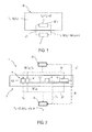
- a temperature-dependent measurement variable M (T o) is at least measured in a closed measuring environment 30.1 of an object 30 by an inter-alloy in a sensor unit 1 Sensor. 4
- the sensor unit 1 is preferably fastened to the object 30 in the region of the measuring environment 30.
- the object 30 may be, for example, a windshield of a vehicle at which a current moisture value and a current temperature value are determined and evaluated for determining a relative humidity value in order to be able to estimate a risk of fogging the windshield 30. Therefore, the corresponding measured values are determined on behalf of the entire windshield 30 in the completed measuring environment 30.1.
- the illustrated sensor unit 1 on the windshield 30 comprises at least one sensor component 2 with a circuit board 2.1, on which at least one sensor 4, which is designed as a combined sensor with a temperature sensor element 4.1 and a humidity sensor element 4.2, and a heat-generating component 6 are arranged are.
- the generated sensor signals which represent the measured variables, are output to an evaluation and control unit 10.
- the evaluation and control unit 10 corrects the at least one temperature-dependent measured variable M (T G ), T G measured by the sensor 4 mathematically with the at least one characteristic curve of the component 6 and outputs the at least one temperature-dependent measured variable M (T G ), T G as at least one corresponding temperature-compensated measured variable (M (T G - ⁇ T), T G - ⁇ T).
- the illustrated sensor unit 1 comprises a further temperature sensor 8, which determines a board temperature T P and outputs to the evaluation and control unit 10.
- the evaluation and control unit 10 can determine the temperature change .DELTA.T in the measuring environment 30. 1 for the correction from the temperature difference between a currently determined board temperature T P and a previously stored board temperature. Additionally or alternatively, the evaluation and control unit 10 from the temperature difference .DELTA.T P between the current board temperature T P and the measured measurement ambient temperature T G determine a further correction factor. To calculate the temperature-compensated temperature, the evaluation and control unit 10 subtracts the determined temperature change ⁇ T from the measured temperature T G.
- the heat-generating component 6 is a rain sensor which detects a non-temperature-dependent measured variable M, which is evaluated, for example, as to whether raindrops are present on the windshield 30.
- the activated rain sensor 6 heats up the measuring environment 30.1 by the operation of an infrared light emitting diode arrangement. Therefore, the measurement of the temperature-dependent measurand M (T G ), T G is falsified when the rain sensor 6 is activated.
- Fig. 3 are different temperature curves, such as the temperature change .DELTA.T in the measurement environment 30.1, the temperature profile T G in the measurement environment 30.1, the temperature profile T 0 on the windshield 30 outside the measurement environment 30.1 and a compensated temperature profile T G - ⁇ T and an activation state V1 of the rain sensor 6 as a heat-generating component applied over time.
- the temperature change ⁇ T in the measuring environment 30. 1 can be calculated and / or measured from the material properties and from the stored characteristic curve of the temporal temperature behavior of the rain sensor 6.
- the course of the measured temperature T G influenced by the temperature change ⁇ T in the measuring environment 30. 1 can be compensated by the determined temperature change ⁇ T.
- the compensated temperature profile T G - ⁇ T is also shown.
- the compensated temperature profile T G -T 0 is substantially the same as the unadulterated temperature profile T o on the windshield 30 outside the measuring environment 30.1.
- Fig. 4 are different courses of relative humidity, such as a profile of the relative humidity M (T G ) in the measuring environment 30.1, the course of the relative humidity M (T 0 ) on the windshield 30 outside the measuring environment 30.1 and a compensated course of the relative humidity M (T G - ⁇ T), the temperature change ⁇ T in the measuring environment 30.1 and an activation state V1 of the rain sensor 6 as a heat-generating component over time.
- the relative humidity M (T G ) determined from the corrupted sensor data decreases when the rain sensor 6 is activated.
- the mathematical compensation yields a compensated measurement curve M (T G - ⁇ T), which corresponds almost to the unadulterated profile of the relative air humidity M (T 0 ) on the windshield 30 outside the measurement environment 30.1.
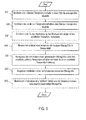
- a temporal temperature behavior of a heat-generating component 6 is determined in a method step S10. This can for example be done once prior to installation in the vehicle or during measurement operation.
- a method step S20 is then the determined temperature behavior of the heat-generating component 6 stored as at least one characteristic.
- the temperature change .DELTA.T of the measuring environment 30. 1, which is generated by the thermal energy of the component 6, is determined from the known temperature behavior of the component 6 and stored in an optional method step S30 shown in dashed lines.
- the at least one temperature-dependent measured variable M (T G ) in the measuring environment 30.1 is determined. Furthermore, other measured variables M can also be detected or determined, which are not dependent on the temperature.
- the at least one measured temperature-dependent measured variable M (T G ) is corrected by the temporal temperature behavior and / or by the determined temperature change ⁇ T.
- the relative humidity M (T G ) is measured or determined, wherein the correction or the temperature compensation on the following approximations according to equation (1) to (3).
- F comp ⁇ M ⁇ T C - ⁇ ⁇ T F G + ⁇ ⁇ F
- Equation (1) shows the basic relationship between the falsified relative humidity F G , the unwanted change in humidity ⁇ F caused by the unwanted temperature change ⁇ T and the course of the compensated relative humidity F comp .
- X a * T G 2 + b * T G + c 2500
- the parameters a, b, c were determined by way of example for the illustrated characteristic curves of the sensors used.
- ⁇ ⁇ F X * F G 100 % * ⁇ ⁇ T
- Equation (3) can be used for the final calculation of the humidity change .DELTA.F to be determined in order to determine and evaluate a current relative humidity value.
- step S60 the temperature-compensated measured variable M (T G - ⁇ T) or F comp is output.
- a further variable is determined from the at least one temperature-dependent measured variable.
- This can be, for example, a probability value for the fitting of the windscreen 30, which can be determined from the relative air humidity and from the compensated temperature profile T G - ⁇ T.
- a corresponding control signal can be output to a blower fan, which can prevent misting of the windscreen 30 by the supply of fresh air.
- Embodiments of the present invention advantageously enable a compensation of temperature-dependent measured variables, the influence of thermal disturbances being minimized and a more accurate measurement result being able to be determined.
Landscapes
- Physics & Mathematics (AREA)
- General Physics & Mathematics (AREA)
- Investigating Or Analyzing Materials Using Thermal Means (AREA)
- Indication And Recording Devices For Special Purposes And Tariff Metering Devices (AREA)
Abstract
Description
Die Erfindung betrifft ein Verfahren zur Temperaturkompensation von mindestens einer temperaturabhängigen Messgröße der im Oberbegriff des Anspruchs 1 genannten Art, sowie eine korrespondierende Vorrichtung zur Temperaturkompensation von mindestens einer temperaturabhängigen Messgröße der im Oberbegriff des Anspruchs 7 genannten Art.The invention relates to a method for temperature compensation of at least one temperature-dependent measured variable referred to in the preamble of
Aus dem Stand der Technik sind Verfahren zur Temperaturkompensation von mindestens einer temperaturabhängigen Messgröße, wie beispielsweise einer Feuchtigkeit und/oder Temperatur auf bzw. an einer Windschutzscheibe bekannt. Eine solche Messvorrichtung ist üblicherweise im Bereich der Windschutzscheibe angebracht und umfasst in der Regel mehrere Sensoren zur Erfassung der Messgrößen sowie eine Auswerte- und Steuereinheit zur Auswertung der Sensordaten.Methods for temperature compensation of at least one temperature-dependent measured variable, such as, for example, a humidity and / or temperature on or on a windshield, are known from the prior art. Such a measuring device is usually mounted in the area of the windshield and as a rule comprises a plurality of sensors for detecting the measured variables and an evaluation and control unit for evaluating the sensor data.
In der Offenlegungsschrift
In der Offenlegungsschrift
Aufgabe der Erfindung ist es, ein Verfahren zur Temperaturkompensation von mindestens einer temperaturabhängigen Messgröße und eine Vorrichtung zur Temperaturkompensation von mindestens einer temperaturabhängigen Messgröße anzugeben, welche durch Berücksichtigung von internen Störgrößen eine genaue Ermittlung der mindestens einen temperaturabhängigen Messgröße in einem geschlossen Messumfeld ermöglichen.The object of the invention is to specify a method for temperature compensation of at least one temperature-dependent measured variable and a device for temperature compensation of at least one temperature-dependent measured variable, which allow a precise determination of the at least one temperature-dependent measured variable in a closed measuring environment by taking into account internal disturbances.
Diese Aufgabe wird erfindungsgemäß durch ein Verfahren zur Temperaturkompensation von mindestens einer temperaturabhängigen Messgröße mit den Merkmalen des Anspruchs 1 und durch eine Vorrichtung zur Temperaturkompensation von mindestens einer temperaturabhängigen Messgröße mit den Merkmalen des Anspruchs 7 gelöst. Weitere die Ausführungsformen der Erfindung in vorteilhafter Weise ausgestaltende Merkmale enthalten die Unteransprüche.This object is achieved by a method for temperature compensation of at least one temperature-dependent variable with the features of
Der mit der Erfindung erzielte Vorteil besteht darin, dass interne Temperaturstörgrößen und deren zeitliche Verläufe ermittelt und gespeichert werden und dann als bekannte Größen bei der Ermittlung von mindestens einer temperaturkompensierten Messgröße berücksichtigt werden können. Dies ermöglicht in vorteilhafter Weise eine genauere Bestimmung der mindestens einen temperaturabhängigen Messgröße, insbesondere bei Eigenerwärmung der Sensoreinheit und/oder bei Erwärmung des Messumfelds. Die unerwünschte Erwärmung kann durch den Messvorgang selbst und/oder durch ein wärmeerzeugendes Bauteil im Messumfeld verursacht werden. In vorteilhafter Weise kann insbesondere der Zustand des wärmeerzeugenden Bauteils berücksichtigt werden, wobei das Bauteil in einem aktiven Zustand Wärme erzeugt und abgibt und in einem nicht aktiven Zustand keine Wärme erzeugt, aber unter Umständen noch Restwärme abgeben kann. Durch die Ermittlung des zeitlichen Verlaufs des Temperaturverhaltens können in vorteilhafter Weise auch eventuell vorhandene Aufwärm- und Abkühlphasen für die Temperaturkompensation berücksichtigt werden.The advantage achieved with the invention is that internal temperature disturbances and their temporal courses are determined and stored and can then be taken into account as known quantities in the determination of at least one temperature-compensated measured variable. This advantageously enables a more accurate determination of the at least one temperature-dependent measured variable, in particular when the sensor unit is self-heating and / or when the measuring environment is heated. The unwanted heating can be caused by the measuring process itself and / or by a heat-generating component in the measuring environment. In an advantageous manner, in particular the state of the heat-generating component can be taken into account, wherein the component generates and releases heat in an active state and generates no heat in a non-active state, but under certain circumstances can still emit residual heat. By determining the temporal course of the temperature behavior, possibly existing warm-up and cool-down phases for the temperature compensation can be taken into account in an advantageous manner.
Der Grundgedanke der Erfindung basiert darauf, dass das zeitliche Temperaturverhalten eines die ungewollte Temperaturänderung bewirkenden Bauteils, welches innerhalb des abgeschlossenen Messumfelds angeordnet ist, ermittelt und gespeichert werden kann, wobei die mindestens eine gemessene temperaturabhängige Messgröße zur Ausgabe von mindestens einer korrespondierenden temperaturkompensierten Messgröße erfindungsgemäß mit dem ermittelten zeitlichen Temperaturverhalten des Bauteils mathematisch korrigiert werden kann.The basic idea of the invention is based on the fact that the temporal temperature behavior of a component causing the unwanted temperature change, which is arranged within the closed measuring environment, can be determined and stored, the at least one measured temperature-dependent measured variable for outputting at least one corresponding temperature-compensated measured variable in accordance with the invention determined temporal temperature behavior of the component can be mathematically corrected.
In vorteilhafter Ausgestaltung des erfindungsgemäßen Verfahrens kann aus dem zeitlichen Temperaturverhalten des Bauteils die Temperaturänderung des Messumfelds und/oder eines im Messumfelds angeordneten Sensors berechnet werden, wobei die mindestens eine gemessene temperaturabhängige Messgröße mathematisch durch die Temperaturänderung korrigiert wird. Die Temperaturänderung des Sensors oder des Messumfelds lässt sich in vorteilhafter Weise unkompliziert durch einen Temperatursensor ermitteln oder bei bekannten Materialeigenschaften mathematisch näherungsweise berechnen. Des Weiteren kann eine mathematische Kompensation der temperarturabhängigen Messgröße in vorteilhafter Weise durch Ersetzen des gemessenen Temperaturwerts durch den über die Temperaturänderung korrigierten Temperaturwert berechnet werden.In an advantageous embodiment of the method according to the invention, the temperature change of the measuring environment and / or a sensor arranged in the measuring environment can be calculated from the temporal temperature behavior of the component, wherein the at least a measured temperature-dependent measured variable is mathematically corrected by the temperature change. The change in temperature of the sensor or of the measuring environment can be determined in an uncomplicated manner advantageously by a temperature sensor or calculated mathematically in the case of known material properties. Furthermore, a mathematical compensation of the temperament-dependent measured variable can advantageously be calculated by replacing the measured temperature value with the temperature value corrected via the temperature change.
In weiterer vorteilhafter Ausgestaltung des erfindungsgemäßen Verfahrens kann eine Platinentemperatur gemessen werden. Die mindestens eine temperaturabhängige gemessene Messgröße und/oder die mindestens eine temperaturkompensierte Messgröße kann durch die Differenz zwischen der gemessenen Platinentemperatur und der Messumfeldtemperatur mathematisch korrigiert werden. Auf diese Weise können weitere Störgrößen, welche zur Verfälschung des Messergebnisses führen können, ausgeschlossen werden.In a further advantageous embodiment of the method according to the invention, a board temperature can be measured. The at least one temperature-dependent measured measured variable and / or the at least one temperature-compensated measured variable can be mathematically corrected by the difference between the measured board temperature and the measuring ambient temperature. In this way, further disturbances, which can lead to the falsification of the measurement result, can be excluded.
In alternativer Ausgestaltung des erfindungsgemäßen Verfahrens kann die gemessene Platinentemperatur abgespeichert werden, wobei aus der aktuell ermittelten Platinentemperatur und einer vorher ermittelten und gespeicherten Platinentemperatur die Temperaturänderung zwischen den beiden Messzeitpunkten berechnet werden kann. Auf diese Weise können die Temperaturänderung zur Temperaturkompensation in vorteilhafter Weise direkt ermittelt, und Fehler in vorteilhafter Weise vermieden werden, welche bei einer mathematischen Näherung auftreten können.In an alternative embodiment of the method according to the invention, the measured board temperature can be stored, wherein from the currently determined board temperature and a previously determined and stored board temperature, the temperature change between the two measurement times can be calculated. In this way, the temperature change for temperature compensation can be advantageously determined directly, and errors can be avoided in an advantageous manner, which can occur in a mathematical approximation.
In weiterer vorteilhafter Ausgestaltung des erfindungsgemäßen Verfahrens zur Temperaturkompensation kann aus der mindestens einen temperaturkompensierten Messgröße mindestens eine weitere Größe vorzugsweise eine relative Luftfeuchtigkeit und/oder eine Beschlagswahrscheinlichkeit für eine Windschutzscheibe ermittelt werden. In vorteilhafter Weise kann der Zusammenhang zwischen der relativen Luftfeuchtigkeit und der Feuchteänderung über die Temperatur als lineare Funktion beschrieben werden. Des Weiteren kann auch der Zusammenhang zwischen der Temperaturänderung und der Feuchteänderung durch eine lineare Funktion beschrieben werden. Somit kann die temperaturkompensierte relative Luftfeuchtigkeit in vorteilhafter Weise über einfache mathematische Funktionen berechnet werden.In a further advantageous embodiment of the method according to the invention for temperature compensation, at least one further variable, preferably a relative humidity and / or a fogging probability for a windshield, can be determined from the at least one temperature-compensated measured variable. Advantageously, the context between the relative humidity and the humidity change over the temperature are described as a linear function. Furthermore, the relationship between the temperature change and the humidity change can be described by a linear function. Thus, the temperature-compensated relative humidity can be calculated advantageously via simple mathematical functions.
In weiterer vorteilhafter Ausgestaltung des erfindungsgemäßen Verfahrens zur Temperaturkompensation können Regentropfen und/oder Licht und/oder Feuchtigkeit und/oder Temperatur auf bzw. an einer Windschutzscheibe über mindestens einen Sensor bestimmt und/oder detektiert und/oder korrigiert und/oder kompensiert werden, wobei die korrespondierenden Sensoren unabhängig voneinander aktiviert werden können. Auf diese Weise können in vorteilhafter Weise nahezu alle sicherheitsrelevanten Einflüsse durch eine Sensoreinheit ermittelt und geeignete Gegenmaßnahmen ergriffen werden. So können beispielsweise Scheibenwischer und/oder ein Lüftergebläse und/oder Lichtfunktionen wie Abblendlicht, Fernlicht, Nebelrückleuchte, Nebellicht usw. aktiviert werden. Des Weiteren können Messergebnisse, welche durch den Betrieb eines anderen Sensors verfälscht werden, durch das beschriebene Verfahren in vorteilhafter Weise korrigiert werden. Beispielsweise kann ein Regensensor durch eine verwendete Infrarotleuchtdiodenanordnung eine Temperaturerhöhung der Windschutzscheibe im Messumfeld bewirken. Aufgrund der erhöhten Temperatur im Messumfeld misst der Feuchtigkeitssensor einen geringeren Feuchtigkeitswert. Dieser gemessene Feuchtigkeitswert entspricht nicht dem Wert der Feuchtigkeit in den andern Bereichen der Windschutzscheibe außerhalb des Messumfelds. Durch den bekannten Temperaturverlauf des aktivierten Regensensors können die Temperaturerhöhung im Messumfeld bestimmt und der gemessene Feuchtigkeitswert korrigiert werden. Dadurch kann beispielsweise ein Beschlagrisiko der Windschutzscheibe korrekt ermittelt und zur Gebläsesteuerung ausgegeben werden.In a further advantageous embodiment of the method according to the invention for temperature compensation, raindrops and / or light and / or moisture and / or temperature can be determined and / or detected and / or corrected and / or compensated on or on a windshield via at least one sensor, wherein the corresponding sensors can be activated independently. In this way, virtually all safety-relevant influences can be determined by a sensor unit and appropriate countermeasures can be taken in an advantageous manner. For example, windscreen wipers and / or a fan blower and / or lighting functions such as low beam, high beam, rear fog light, fog light, etc. can be activated. Furthermore, measurement results which are falsified by the operation of another sensor can be advantageously corrected by the described method. For example, a rain sensor can cause an increase in the temperature of the windshield in the measurement environment due to the use of an infrared light-emitting diode arrangement. Due to the increased temperature in the measurement environment, the humidity sensor measures a lower humidity value. This measured moisture value does not match the value of moisture in the other areas of the windshield outside the measurement environment. Due to the known temperature profile of the activated rain sensor, the temperature increase in the measuring environment can be determined and the measured moisture value can be corrected. As a result, for example, a risk of misting the windshield can be determined correctly and output to the blower control.
Die erfindungsgemäße Vorrichtung zur Temperaturkompensation von mindestens einer temperaturabhängigen Messgröße, welche von einem in einer Sensoreinheit intergierten Sensor in einem Messumfeld eines Objekts gemessen wird, umfasst eine Auswerte-und Steuereinheit, wobei eine ungewollte Temperaturänderung das mindestens eine im Messumfeld gemessene Messergebnis verfälscht. Erfindungsgemäß ist das zeitliche Temperaturverhalten eines Bauteils, welches innerhalb des abgeschlossenen Messumfelds angeordnet ist und die ungewollte Temperaturänderung des Messumfelds bewirkt, als mindestens eine Kennlinie in einer Speichereinheit hinterlegt, und die Auswerte- und Steuereinheit korrigiert die mindestens eine vom Sensor gemessene temperaturabhängige Messgröße mit der mindestens einen Kennlinie des Bauteils mathematisch. Des Weiteren gibt die Auswerte- und Steuereinheit die mindestens eine temperaturabhängige Messgröße als mindestens eine korrespondierende temperaturkompensierten Messgröße aus. In vorteilhafter Weise können somit anordnungsbedingte Temperaturstörgrößen erfasst und deren Auswirkungen minimiert werden.The device according to the invention for temperature compensation of at least one temperature-dependent measured variable, which is measured by a sensor integrated in a sensor unit in a measuring environment of an object, comprises an evaluation and control unit, wherein an undesired temperature change falsifies the at least one measured result measured in the measuring environment. According to the invention, the temporal temperature behavior of a component, which is arranged within the closed measuring environment and causes the unintentional temperature change of the measurement environment, deposited as at least one characteristic in a memory unit, and the evaluation and control unit corrects the at least one temperature-dependent measured variable measured by the sensor with the at least a characteristic of the component mathematically. Furthermore, the evaluation and control unit outputs the at least one temperature-dependent measured variable as at least one corresponding temperature-compensated measured variable. Advantageously, thus arrangement-related temperature disturbances can be detected and their effects are minimized.
In vorteilhafter Ausgestaltung der erfindungsgemäßen Vorrichtung kann ein Temperatursensor eine Platinentemperatur bestimmen und an die Auswerte- und Steuereinheit ausgeben, wobei die Auswerte- und Steuereinheit aus der Temperaturdifferenz zwischen einer aktuell ermittelten Platinentemperatur und einer vorherigen gespeicherten Platinentemperatur die Temperaturänderung ermitteln und/oder aus der Differenz zwischen der bestimmten Platinentemperatur und einer gemessenen Messumfeldtemperatur einen weiteren Korrekturfaktor ermitteln kann. In vorteilhafter Weise können durch einen Temperatursensor die mathematischen Nährungen gegebenenfalls korrigiert werden, um die Näherungsfehler zu minimieren.In an advantageous embodiment of the device according to the invention, a temperature sensor can determine a board temperature and output to the evaluation and control unit, wherein the evaluation and control unit from the temperature difference between a currently determined board temperature and a previously stored board temperature determine the temperature change and / or from the difference between the determined board temperature and a measured measuring ambient temperature can determine a further correction factor. Advantageously, the mathematical constraints can optionally be corrected by a temperature sensor to minimize the approximation errors.
In weiterer vorteilhafter Ausgestaltung der erfindungsgemäßen Vorrichtung umfasst die Sensoreinheit einen Regensensor und/oder einen Lichtsensor und/oder einen Feuchtigkeitssensor und/oder Temperatursensor, wobei die Sensoren korrespondierende Messgrößen in dem Messumfeld einer Windschutzscheibe messen und/oder detektieren. Des Weiteren können die einzelnen Sensoren unabhängig voneinander aktiviert werden. Auf diese Weise können in vorteilhafter Weise nahezu alle äußeren Einflüsse auf eine Windschutzschiebe durch eine Sensoreinheit ermittelt und/oder detektiert werden. Durch die Temperaturkompensation können Messfehler, welche durch das Temperaturverhalten von anderen in der Sensoreinheit aktiven Sensoren verursacht werden, eliminiert werden.In a further advantageous embodiment of the device according to the invention, the sensor unit comprises a rain sensor and / or a light sensor and / or a moisture sensor and / or temperature sensor, the sensors corresponding Measure and / or detect measured variables in the measurement environment of a windshield. Furthermore, the individual sensors can be activated independently of each other. In this way, almost all external influences on a windshield slide can be advantageously determined and / or detected by a sensor unit. The temperature compensation can be used to eliminate measurement errors caused by the temperature behavior of other sensors active in the sensor unit.
In weiterer vorteilhafter Ausgestaltung der erfindungsgemäßen Vorrichtung ermittelt die Auswerte und Steuereinheit aus dem ermittelten temperaturkompensierten Feuchtigkeitswert und dem ermittelten temperaturkompensierten Temperaturwert einen relativen Luftfeuchtigkeitswert, wobei die Auswerte- und Steuereinheit aus dem ermittelten relativen Luftfeuchtigkeitswert einen Wahrscheinlichkeitswert ermittelt, mit welchem die Windschutzscheibe beschlägt. Auf diese Weise können das Beschlagsrisiko genauer bestimmt und erforderliche Maßnahmen rechtzeitig ergriffen werden, um ein Beschlagen der Windschutzscheibe zu vermeiden.In a further advantageous embodiment of the device according to the invention, the evaluation and control unit determines a relative humidity value from the determined temperature-compensated humidity value and the determined temperature-compensated temperature value, wherein the evaluation and control unit determines from the determined relative humidity value a probability value with which the windshield fogs. In this way, the risk of fogging can be determined more accurately and necessary measures can be taken in good time to avoid fogging of the windscreen.
Nachfolgend wird ein Ausführungsbeispiel der Erfindung anhand einer zeichnerischen Darstellung näher erläutert. In der Zeichnung bezeichnen gleiche Bezugszeichen Komponenten bzw. Elemente, die gleiche bzw. analoge Funktionen ausführen.Hereinafter, an embodiment of the invention will be explained in more detail with reference to a drawing. In the drawing, like reference numerals designate components that perform the same or analog functions.
In der Darstellung zeigt:
- Fig. 1
- Ein schematisches Blockschaltbild eines Ausführungsbeispiels einer erfindungsgemäßen Vorrichtung zur Temperaturkompensation von temperaturabhängigen. Messgrößen für ein Fahrzeug.
- Fig. 2
- Ein erweitertes schematisches Blockschaltbild des Ausführungsbeispiels der erfindungsgemäßen Vorrichtung zur Temperaturkompensation von temperaturabhängigen Messgrößen für ein Fahrzeug aus
Fig. 1 . - Fig. 3
- Ein Kennliniendiagramm mit mehreren erfassten Temperaturkennlinien.
- Fig. 4
- Ein Kennliniendiagramm mit mehreren erfassten Kennlinien der relativen Luftfeuchtigkeit.
- Fig. 5 Ein
- Flussdiagramm eines Ausführungsbeispiels eines erfindungsgemäßen Verfahrens zur Temperaturkompensation von mindestens einer temperaturabhängigen Messgröße.
- Fig. 1
- A schematic block diagram of an embodiment of an inventive device for temperature compensation of temperature-dependent. Measured variables for a vehicle.
- Fig. 2
- An expanded schematic block diagram of the embodiment of the device according to the invention for Temperature compensation of temperature-dependent measured variables for a vehicle
Fig. 1 , - Fig. 3
- A characteristic diagram with several recorded temperature characteristics.
- Fig. 4
- A characteristic diagram with several recorded relative humidity curves.
- Fig. 5 a
- Flowchart of an embodiment of a method according to the invention for temperature compensation of at least one temperature-dependent measured variable.
Wie aus
Durch den Betrieb der Sensoreinheit 1 ist die im Messumfeld 30.1 gemessene Temperatur TG in der Regel höher als die tatsächliche Temperatur To an der Windschutzscheibe 30 außerhalb des Messumfelds 30.1. Des Weiteren ist auch die im Messumfeld 30.1 gemessene Feuchtigkeit und die daraus ermittelte relative Luftfeuchtigkeit M(TG) durch die im Messumfeld 30.1 erhöhte Temperatur TG=To+ΔT verfälscht, so dass innerhalb des Messumfeld 30.1 ein Feuchtigkeitswert gemessen wird, welcher geringer als ein außerhalb des Messumfelds 30.1 an der Windschutzscheibe 30 tatsächlich vorliegender Feuchtigkeitswert ist. Das bedeutet, dass die verfälschte relative Luftfeuchtigkeit M(TG), welche aus dem innerhalb des Messumfelds 30.1 erfassten Feuchtigkeitswert ermittelt wird, ebenfalls geringer ist, als die tatsächliche relative Luftfeuchtigkeit M(T0), welche aus dem außerhalb des Messumfelds 30.1 an der Windschutzscheibe 30 tatsächlich vorliegenden Feuchtigkeitswert ermittelt wird.As a result of the operation of the
Wie aus
Erfindungsgemäß ist das zeitliche Temperaturverhalten des wärmeerzeugenden Bauteils 6, welches innerhalb des abgeschlossenen Messumfelds 30.1 auf der Platine 2.1, des Sensorbauteils 2 der Sensoreinheit 1 angeordnet ist und die ungewollte Temperaturänderung ΔT des Messumfelds 30.1 bewirkt, als mindestens eine Kennlinie in einer Speichereinheit der Auswerte und Steuereinheit 10 hinterlegt. Hierbei korrigiert die Auswerte- und Steuereinheit 10 die mindestens eine vom Sensor 4 gemessene temperaturabhängige Messgröße M(TG), TG mit der mindestens einen Kennlinie des Bauteils 6 mathematisch und gibt die mindestens eine temperaturabhängige Messgröße M(TG), TG als mindestens eine korrespondierende temperaturkompensierten Messgröße (M(TG-ΔT), TG-ΔT) aus.According to the invention, the temporal temperature behavior of the heat-generating
Wie aus
Wie aus
In
Wie aus
In
Wie aus
Im dargestellten Ausführungsbeispiel wird in einem gestrichelt dargestellten optionalen Verfahrensschritt S30 die Temperaturänderung ΔT des Messumfelds 30.1, welche durch die Wärmeenergie des Bauteils 6 erzeugt wird, aus dem bekannten Temperaturverhalten des Bauteils 6 ermittelt und gespeichert.In the exemplary embodiment illustrated, the temperature change .DELTA.T of the measuring
Im Verfahrensschritt S40 wird die mindestens eine temperaturabhängige Messgröße M(TG) im Messumfeld 30.1 ermittelt. Des Weiteren können auch andere Messgrößen M erfasst bzw. ermittelt werden, welche nicht von der Temperatur abhängig sind.In method step S40, the at least one temperature-dependent measured variable M (T G ) in the measuring environment 30.1 is determined. Furthermore, other measured variables M can also be detected or determined, which are not dependent on the temperature.
Im Verfahrensschritt S50 wird die mindestens eine gemessene temperaturabhängige Messgröße M(TG) durch das zeitliche Temperaturverhalten und/oder durch die ermittelte Temperaturänderung ΔT korrigiert. Im dargestellten Ausführungsbeispiel wird beispielsweise die relative Luftfeuchtigkeit M(TG) gemessen bzw. ermittelt, wobei die Korrektur bzw. die Temperaturkompensation über die folgenden Näherungen gemäß Gleichung (1) bis (3) erfolgt. 
Gleichung (1) zeigt den prinzipiellen Zusammenhang zwischen der verfälschten relativen Luftfeuchtigkeit FG, den durch die ungewollte Temperaturänderung ΔT bewirkten ungewollte Feuchteänderung ΔF und dem Verlauf der kompensierten relativen Luftfeuchtigkeit Fkomp. 
Gleichung (2) zeigt eine vereinfachte quadratische Näherung, wobei X ein Zwischenergebnis mit a=-1, b=165, c=-18568 repräsentiert, welches in der endgültigen Gleichung (3) für die zu ermittelnde Feuchteänderung ΔF eingesetzt wird. Die Parameter a, b, c wurden beispielhaft für die dargestellten Kennlinien-Verläufe der verwendeten Sensoren bestimmt. 
Gleichung (3) kann zur endgültigen Berechnung der zu ermittelnden Feuchteänderung ΔF eingesetzt werden, um einen aktuellen relativen Luftfeuchtigkeitswert zu bestimmen und auszuwerten.Equation (3) can be used for the final calculation of the humidity change .DELTA.F to be determined in order to determine and evaluate a current relative humidity value.
Im Verfahrensschritt S60 wird die temperaturkompensierte Messgröße M(TG-ΔT) bzw. Fkomp ausgegeben.In method step S60, the temperature-compensated measured variable M (T G -ΔT) or F comp is output.
Im gestrichelt dargestellten optionalen Verfahrensschritt S70 wird eine weitere Größe aus der mindestens einen temperaturabhängigen Messgröße bestimmt. Dies kann beispielsweise ein Wahrscheinlichkeitswert für den Beschlag der Windschutzscheibe 30 sein, welcher aus der relativen Luftfeuchtigkeit und aus dem kompensierten Temperaturverlauf TG-ΔT ermittelt werden kann. Auf diese Weise kann ein entsprechendes Steuersignal an einen Gebläselüfter ausgegeben werden, welcher durch die Zufuhr von Frischluft ein Beschlagen der Windschutzscheibe 30 verhindern kann.In the optional method step S70 shown in dashed lines, a further variable is determined from the at least one temperature-dependent measured variable. This can be, for example, a probability value for the fitting of the
Ausführungsformen der vorliegenden Erfindung ermöglichen in vorteilhafter Weise eine Kompensation von temperaturabhängigen Messgrößen, wobei die Beeinflussung von thermischen Störgrößen minimiert und ein genaueres Messergebnis ermittelt werden können.Embodiments of the present invention advantageously enable a compensation of temperature-dependent measured variables, the influence of thermal disturbances being minimized and a more accurate measurement result being able to be determined.
Claims (10)
dadurch gekennzeichnet,
dass das zeitliche Temperaturverhalten eines die ungewollte Temperaturänderung (ΔT) bewirkenden Bauteils (6), welches innerhalb des abgeschlossenen Messumfelds (30.1) angeordnet ist, ermittelt und gespeichert wird,
wobei die mindestens eine gemessene temperaturabhängige Messgröße (M(TG), TG) zur Ausgabe von mindestens einer korrespondierenden temperaturkompensierten Messgröße (M(TG-ΔT), TG-ΔT) mit dem ermittelten zeitlichen Temperaturverhalten des Bauteils (6) mathematisch korrigiert wird.Method for temperature compensation of at least one temperature-dependent measured variable (M (T), T), which is measured in a measuring environment (30.1), wherein the at least one measuring result (M (T G ), T G ) is falsified,
characterized,
that the temporal temperature behavior of a component (6) causing the unwanted temperature change (ΔT), which is arranged within the closed measuring environment (30.1), is determined and stored,
wherein the at least one measured temperature-dependent measured variable (M (T G ), T G ) for outputting at least one corresponding temperature-compensated measured variable (M (T G -ΔT), T G -ΔT) with the determined temporal temperature behavior of the component (6) mathematically is corrected.
dadurch gekennzeichnet,
dass aus dem zeitlichen Temperaturverhalten des Bauteils (6) die Temperaturänderung (ΔT) des Messumfelds (30.1) und/oder eines im Messumfeld (30.1) angeordneten Sensors (4) berechnet wird, wobei die mindestens eine gemessene temperaturabhängige Messgröße (M(TG), TG) mathematisch durch die Temperaturänderung (ΔT) korrigiert wird.Method according to claim 1,
characterized,
that from the time-temperature behavior of the component (6) the change in temperature (At) arranged in the measurement environment (30.1) and / or in the measuring environment (30.1) sensor (4) is calculated, wherein the at least one measured temperature-dependent measured variable (M (T G) , T G ) is mathematically corrected by the temperature change (ΔT).
dadurch gekennzeichnet,
dass eine Platinentemperatur (TP) gemessen wird, wobei die mindestens eine temperaturabhängige gemessene Messgröße (M(TG), TG) und/oder die mindestens eine temperaturkompensierte Messgröße (M(TG-ΔT), TG-ΔT) durch die Differenz (ΔTP) zwischen der gemessenen Platinentemperatur (TP) und der Messumfeldtemperatur mathematisch korrigiert wird.Method according to claim 1 or 2,
characterized,
that a platinum temperature (T P) is measured, wherein the at least one temperature-dependent measured variable (M (T G ), T G ) and / or the at least one temperature-compensated measured variable (M (T G -ΔT), T G -ΔT) by the difference (ΔT P ) between the measured board temperature (T P ) and the measurement environment temperature is corrected mathematically.
dadurch gekennzeichnet,
dass die gemessene Platinentemperatur (TP) abspeichert wird, wobei aus der aktuell ermittelten Platinentemperatur (TP) und einer gespeicherten Platinentemperatur die Temperaturänderung (ΔT) berechnet wird.Method according to claim 2 or 3,
characterized,
that the measured board temperature (T P ) is stored, wherein from the currently determined board temperature (T P ) and a stored board temperature, the temperature change (.DELTA.T) is calculated.
dass aus der mindestens einen temperaturkompensierten Messgröße (M(TG-ΔT), TG-ΔT) mindestens eine weitere Größe vorzugsweise eine relative Luftfeuchtigkeit und/oder eine Beschlagswahrscheinlichkeit für eine Windschutzschiebe ermittelt wird.Method according to one of the preceding claims 1 to 4, characterized
that at least one further variable, preferably a relative air humidity and / or a fogging probability for a windscreen slide, is determined from the at least one temperature-compensated measured variable (M (T G -ΔT), T G -ΔT).
dass Regentropfen und/oder Licht und/oder Feuchtigkeit und Temperatur auf bzw. an einer Windschutzscheibe über mindestens einen Sensor (4. 4.1, 4.2, 6) bestimmt und/oder detektiert und/oder korrigiert und/oder kompensiert werden, wobei mehrere Sensoren (4, 4.1, 4.2, 6) unabhängig voneinander aktiviert werden.Method according to one of the preceding claims 1 to 5, characterized
that raindrops and / or light and / or moisture and temperature on or on a windscreen are determined and / or detected and / or corrected and / or compensated via at least one sensor (4.1, 4.2, 6), wherein a plurality of sensors ( 4, 4.1, 4.2, 6) are activated independently of each other.
dadurch gekennzeichnet,
dass das zeitliche Temperaturverhalten eines Bauteils (6), welches innerhalb des abgeschlossenen Messumfelds (30.1) angeordnet ist und die ungewollte Temperaturänderung (ΔT) des Messumfelds (30.1) bewirkt, als mindestens eine Kennlinie in einer Speichereinheit hinterlegt ist, wobei eine Auswerte- und Steuereinheit (10) die mindestens eine vom Sensor (1) gemessene temperaturabhängige Messgröße (M(TG), TG) mit der mindestens einen Kennlinie des Bauteils (6) mathematisch korrigiert und die mindestens eine temperaturabhängige Messgröße als mindestens eine korrespondierende temperaturkompensierten Messgröße (M(TG-ΔT), TG-ΔT) ausgibt.Device for temperature compensation of a sensor (4) integrated in a sensor unit (1), which measures at least one temperature-dependent measured variable (M (T), T) in a measuring environment (30.1) of an object (30), wherein an undesired temperature change (ΔT) causes the at least a measurement result measured in the measurement environment (30.1) (M (T G ), T G ),
characterized,
that the time-temperature behavior of a component (6) which is disposed within the closed measurement environment (30.1) and the unwanted change in temperature (At) of the measurement environment (30.1) causes than at least one characteristic is stored in a memory unit, wherein an evaluation and control unit (10) the at least one of the sensor (1) measured temperature-dependent measured variable (M (T G ), T G ) with the at least one characteristic of the component (6) mathematically corrected and the at least one temperature-dependent measured variable as at least one corresponding temperature-compensated measured variable (M (T G -ΔT), T G -ΔT).
dass ein Temperatursensor (8) die Platinentemperatur (TP) bestimmt und an die Auswerte- und Steuereinheit (10) ausgibt, wobei die Auswerte-und Steuereinheit (10) aus der Temperaturdifferenz zwischen einer aktuell ermittelten Platinentemperatur (TP) und einer vorherigen gespeicherten Platinentemperatur die Temperaturänderung (ΔT) ermittelt und/oder aus der Temperaturdifferenz (ΔTP) zwischen der bestimmten Platinentemperatur (TP) und einer gemessenen Messumfeldtemperatur (TG) einen weiteren Korrekturfaktor ermittelt.Device for temperature compensation according to claim 7, characterized in that
that a temperature sensor (8) determines the board temperature (T P) and to the evaluation and control unit (10), wherein the evaluation and control unit (10) from the temperature difference between a currently determined platinum temperature (T P) and a previous stored Board temperature, the temperature change (.DELTA.T) determined and / or from the temperature difference (.DELTA.T P ) between the particular board temperature (T P ) and a measured measuring ambient temperature (T G ) determines a further correction factor.
dadurch gekennzeichnet,
dass die Sensoreinheit (1) einen Regensensor (6) und/oder einen Lichtsensor und/oder einen Feuchtigkeitssensor (4.1) und/oder einen Temperatursensor (4.2) aufweist, wobei die Sensoren (4.1, 4.2, 6) korrespondierende Größen in dem Messumfeld (30.1) einer Windschutzscheibe messen und/oder detektieren, wobei die Sensoren (4.1, 4.2, 6) unabhängig voneinander aktivierbar sind.Device according to claim 7 or 8,
characterized,
in that the sensor unit (1) has a rain sensor (6) and / or a light sensor and / or a moisture sensor (4.1) and / or a temperature sensor (4.2), wherein the sensors (4.1, 4.2, 6) have corresponding magnitudes in the measurement environment ( 30.1) of a windshield and / or detect, wherein the sensors (4.1, 4.2, 6) are independently activatable.
dadurch gekennzeichnet,
dass die Auswerte und Steuereinheit (10) aus dem ermittelten temperaturkompensierten Feuchtigkeitswert und dem ermittelten temperaturkompensierten Temperaturwert (TG-ΔT) einen relativen Luftfeuchtigkeitswert ermittelt, wobei die Auswerte- und Steuereinheit (10) aus dem ermittelten relativen Luftfeuchtigkeitswert einen Wahrscheinlichkeitswert ermittelt, mit welchem die Windschutzscheibe beschlägt.Device for temperature compensation according to one of the preceding claims 7 to 9,
characterized,
in that the evaluation and control unit (10) determines a relative humidity value from the determined temperature-compensated humidity value and the determined temperature-compensated temperature value (T G -ΔT), wherein the evaluation and control unit (10) determines from the determined relative humidity value a probability value with which the Windshield fogged.
Applications Claiming Priority (1)
| Application Number | Priority Date | Filing Date | Title |
|---|---|---|---|
| DE201110107973 DE102011107973A1 (en) | 2011-07-16 | 2011-07-16 | Method and device for temperature compensation of at least one temperature-dependent measured variable |
Publications (3)
| Publication Number | Publication Date |
|---|---|
| EP2589941A2 true EP2589941A2 (en) | 2013-05-08 |
| EP2589941A3 EP2589941A3 (en) | 2015-08-12 |
| EP2589941B1 EP2589941B1 (en) | 2016-09-21 |
Family
ID=46545661
Family Applications (1)
| Application Number | Title | Priority Date | Filing Date |
|---|---|---|---|
| EP12176513.5A Active EP2589941B1 (en) | 2011-07-16 | 2012-07-16 | Method and device for compensating for the temperature of at least one temperature-dependent parameter |
Country Status (2)
| Country | Link |
|---|---|
| EP (1) | EP2589941B1 (en) |
| DE (1) | DE102011107973A1 (en) |
Cited By (2)
| Publication number | Priority date | Publication date | Assignee | Title |
|---|---|---|---|---|
| CN113518287A (en) * | 2021-07-14 | 2021-10-19 | 歌尔光学科技有限公司 | Method for adjusting device state, terminal device and computer readable storage medium |
| WO2023093948A1 (en) * | 2021-11-26 | 2023-06-01 | Conti Temic Microelectronic Gmbh | Method for determining the ambient temperature of a control device |
Families Citing this family (2)
| Publication number | Priority date | Publication date | Assignee | Title |
|---|---|---|---|---|
| DE102016210852B4 (en) | 2016-06-17 | 2023-09-14 | Volkswagen Aktiengesellschaft | Lighting control device and motor vehicle |
| DE102021200173A1 (en) | 2021-01-11 | 2022-07-14 | Robert Bosch Gesellschaft mit beschränkter Haftung | Method for determining temperature-related deviations for a sensor system and sensor system |
Family Cites Families (7)
| Publication number | Priority date | Publication date | Assignee | Title |
|---|---|---|---|---|
| DE19907401A1 (en) | 1999-02-20 | 2000-08-24 | Behr Gmbh & Co | Automobile windscreen automatic de-misting method has humidity signal provided by humidity sensor corrected in dependence on detected incident solar radiation |
| US7204130B2 (en) * | 2002-12-03 | 2007-04-17 | Ppg Industries Ohio, Inc. | Windshield moisture detector |
| DE102005006859A1 (en) * | 2005-02-15 | 2006-08-17 | Vogt Electronic Components Gmbh | Humidification measuring system for use in vehicle, has temperature compensation mechanism providing temperature corrected output signal corresponding to different behavior during change of temperature or humidification condition of areas |
| JP4779860B2 (en) * | 2006-08-03 | 2011-09-28 | 株式会社デンソー | Raindrop amount detection device and wiper control device |
| US7696710B2 (en) * | 2006-10-30 | 2010-04-13 | Agc Automotive Americas R&D, Inc. | Method of sensing an amount of moisture on a surface of a substrate with temperature compensation |
| DE102007005544B4 (en) | 2007-02-06 | 2008-10-02 | Behr-Hella Thermocontrol Gmbh | Measurement of the relative humidity in the interior of a vehicle and calibration of a humidity sensor |
| EP2012092B1 (en) * | 2007-07-04 | 2010-12-01 | Micronas GmbH | Measuring device with at least two sensors |
-
2011
- 2011-07-16 DE DE201110107973 patent/DE102011107973A1/en not_active Withdrawn
-
2012
- 2012-07-16 EP EP12176513.5A patent/EP2589941B1/en active Active
Cited By (2)
| Publication number | Priority date | Publication date | Assignee | Title |
|---|---|---|---|---|
| CN113518287A (en) * | 2021-07-14 | 2021-10-19 | 歌尔光学科技有限公司 | Method for adjusting device state, terminal device and computer readable storage medium |
| WO2023093948A1 (en) * | 2021-11-26 | 2023-06-01 | Conti Temic Microelectronic Gmbh | Method for determining the ambient temperature of a control device |
Also Published As
| Publication number | Publication date |
|---|---|
| EP2589941A3 (en) | 2015-08-12 |
| EP2589941B1 (en) | 2016-09-21 |
| DE102011107973A1 (en) | 2013-01-17 |
Similar Documents
| Publication | Publication Date | Title |
|---|---|---|
| DE112015004829B4 (en) | ULTRASONIC OBJECT DETECTION DEVICE | |
| EP3134742B1 (en) | Temperature correction for current measuring via shunt | |
| EP2589941B1 (en) | Method and device for compensating for the temperature of at least one temperature-dependent parameter | |
| DE102011112675B4 (en) | Method for more accurate temperature sensing using thermistors | |
| DE102007000407B4 (en) | Raindrop quantity detecting device and having this wiper control system | |
| DE102011084278B4 (en) | Method and device for preventing vehicle windows from fogging up | |
| DE10127929B4 (en) | Raindrop detection method and raindrop detection device with a compensation of a temperature-dependent property | |
| DE112019003505T5 (en) | PRECIPITATION MEASURING DEVICE | |
| EP1373033B1 (en) | Sensor for detecting filth and/or humidity on the outer side of a glass pane | |
| DE112019004439T5 (en) | DISTANCE MEASURING DEVICE | |
| DE10229628A1 (en) | Sensor unit, device and method for avoiding condensation on a surface | |
| DE102007026033A1 (en) | Method for detecting icing of a radar sensor serving to detect objects of a driver assistance system provided in a motor vehicle | |
| DE10342333B4 (en) | fogging sensor | |
| DE102012200592A1 (en) | Method and device for determining a state of a sensor | |
| EP1044858B1 (en) | Method for getting a correction factor to compensate for the temperature drift in the intensity of the beams of an LED | |
| DE10342327B4 (en) | fogging sensor | |
| EP1470968A1 (en) | Occupant detection system for vehicles | |
| DE102018213494A1 (en) | Optical sensor, rain sensor and vehicle | |
| DE102012023366B4 (en) | Method for operating a heater that can be used in a motor vehicle, a heater for a component of a motor vehicle and a motor vehicle | |
| EP1285830B1 (en) | Method for compensating the temperature influence on the sending capacity of a LED-transmitter and/or on the sensitivity of a receiver | |
| EP2209675B1 (en) | Method for operating a rain sensor, particularly for motor vehicles | |
| DE112019007682T5 (en) | In-vehicle camera power control apparatus and power control method | |
| DE102007005544A1 (en) | Measurement of the relative humidity in the interior of a vehicle and calibration of a humidity sensor | |
| DE102016221384A1 (en) | Method and device for operating a safety system of a motor vehicle, safety system for a motor vehicle | |
| DE10341955B3 (en) | Determining external temperature for motor vehicle involves using temperature sensor, computer model with variable cooling time constant representing cooling process rate for operating condition |
Legal Events
| Date | Code | Title | Description |
|---|---|---|---|
| PUAI | Public reference made under article 153(3) epc to a published international application that has entered the european phase |
Free format text: ORIGINAL CODE: 0009012 |
|
| AK | Designated contracting states |
Kind code of ref document: A2 Designated state(s): AL AT BE BG CH CY CZ DE DK EE ES FI FR GB GR HR HU IE IS IT LI LT LU LV MC MK MT NL NO PL PT RO RS SE SI SK SM TR |
|
| AX | Request for extension of the european patent |
Extension state: BA ME |
|
| PUAL | Search report despatched |
Free format text: ORIGINAL CODE: 0009013 |
|
| AK | Designated contracting states |
Kind code of ref document: A3 Designated state(s): AL AT BE BG CH CY CZ DE DK EE ES FI FR GB GR HR HU IE IS IT LI LT LU LV MC MK MT NL NO PL PT RO RS SE SI SK SM TR |
|
| AX | Request for extension of the european patent |
Extension state: BA ME |
|
| RIC1 | Information provided on ipc code assigned before grant |
Ipc: G01D 3/028 20060101ALI20150708BHEP Ipc: G01K 1/20 20060101AFI20150708BHEP |
|
| 17P | Request for examination filed |
Effective date: 20160210 |
|
| RBV | Designated contracting states (corrected) |
Designated state(s): AL AT BE BG CH CY CZ DE DK EE ES FI FR GB GR HR HU IE IS IT LI LT LU LV MC MK MT NL NO PL PT RO RS SE SI SK SM TR |
|
| GRAP | Despatch of communication of intention to grant a patent |
Free format text: ORIGINAL CODE: EPIDOSNIGR1 |
|
| INTG | Intention to grant announced |
Effective date: 20160414 |
|
| GRAS | Grant fee paid |
Free format text: ORIGINAL CODE: EPIDOSNIGR3 |
|
| GRAA | (expected) grant |
Free format text: ORIGINAL CODE: 0009210 |
|
| AK | Designated contracting states |
Kind code of ref document: B1 Designated state(s): AL AT BE BG CH CY CZ DE DK EE ES FI FR GB GR HR HU IE IS IT LI LT LU LV MC MK MT NL NO PL PT RO RS SE SI SK SM TR |
|
| REG | Reference to a national code |
Ref country code: GB Ref legal event code: FG4D Free format text: NOT ENGLISH |
|
| REG | Reference to a national code |
Ref country code: CH Ref legal event code: EP |
|
| REG | Reference to a national code |
Ref country code: AT Ref legal event code: REF Ref document number: 831428 Country of ref document: AT Kind code of ref document: T Effective date: 20161015 |
|
| REG | Reference to a national code |
Ref country code: IE Ref legal event code: FG4D Free format text: LANGUAGE OF EP DOCUMENT: GERMAN |
|
| REG | Reference to a national code |
Ref country code: DE Ref legal event code: R096 Ref document number: 502012008300 Country of ref document: DE |
|
| REG | Reference to a national code |
Ref country code: LT Ref legal event code: MG4D Ref country code: NL Ref legal event code: MP Effective date: 20160921 |
|
| PG25 | Lapsed in a contracting state [announced via postgrant information from national office to epo] |
Ref country code: FI Free format text: LAPSE BECAUSE OF FAILURE TO SUBMIT A TRANSLATION OF THE DESCRIPTION OR TO PAY THE FEE WITHIN THE PRESCRIBED TIME-LIMIT Effective date: 20160921 Ref country code: RS Free format text: LAPSE BECAUSE OF FAILURE TO SUBMIT A TRANSLATION OF THE DESCRIPTION OR TO PAY THE FEE WITHIN THE PRESCRIBED TIME-LIMIT Effective date: 20160921 Ref country code: LT Free format text: LAPSE BECAUSE OF FAILURE TO SUBMIT A TRANSLATION OF THE DESCRIPTION OR TO PAY THE FEE WITHIN THE PRESCRIBED TIME-LIMIT Effective date: 20160921 Ref country code: NO Free format text: LAPSE BECAUSE OF FAILURE TO SUBMIT A TRANSLATION OF THE DESCRIPTION OR TO PAY THE FEE WITHIN THE PRESCRIBED TIME-LIMIT Effective date: 20161221 |
|
| PG25 | Lapsed in a contracting state [announced via postgrant information from national office to epo] |
Ref country code: NL Free format text: LAPSE BECAUSE OF FAILURE TO SUBMIT A TRANSLATION OF THE DESCRIPTION OR TO PAY THE FEE WITHIN THE PRESCRIBED TIME-LIMIT Effective date: 20160921 Ref country code: SE Free format text: LAPSE BECAUSE OF FAILURE TO SUBMIT A TRANSLATION OF THE DESCRIPTION OR TO PAY THE FEE WITHIN THE PRESCRIBED TIME-LIMIT Effective date: 20160921 Ref country code: LV Free format text: LAPSE BECAUSE OF FAILURE TO SUBMIT A TRANSLATION OF THE DESCRIPTION OR TO PAY THE FEE WITHIN THE PRESCRIBED TIME-LIMIT Effective date: 20160921 Ref country code: GR Free format text: LAPSE BECAUSE OF FAILURE TO SUBMIT A TRANSLATION OF THE DESCRIPTION OR TO PAY THE FEE WITHIN THE PRESCRIBED TIME-LIMIT Effective date: 20161222 |
|
| PG25 | Lapsed in a contracting state [announced via postgrant information from national office to epo] |
Ref country code: EE Free format text: LAPSE BECAUSE OF FAILURE TO SUBMIT A TRANSLATION OF THE DESCRIPTION OR TO PAY THE FEE WITHIN THE PRESCRIBED TIME-LIMIT Effective date: 20160921 Ref country code: RO Free format text: LAPSE BECAUSE OF FAILURE TO SUBMIT A TRANSLATION OF THE DESCRIPTION OR TO PAY THE FEE WITHIN THE PRESCRIBED TIME-LIMIT Effective date: 20160921 |
|
| PG25 | Lapsed in a contracting state [announced via postgrant information from national office to epo] |
Ref country code: PL Free format text: LAPSE BECAUSE OF FAILURE TO SUBMIT A TRANSLATION OF THE DESCRIPTION OR TO PAY THE FEE WITHIN THE PRESCRIBED TIME-LIMIT Effective date: 20160921 Ref country code: PT Free format text: LAPSE BECAUSE OF FAILURE TO SUBMIT A TRANSLATION OF THE DESCRIPTION OR TO PAY THE FEE WITHIN THE PRESCRIBED TIME-LIMIT Effective date: 20170123 Ref country code: BG Free format text: LAPSE BECAUSE OF FAILURE TO SUBMIT A TRANSLATION OF THE DESCRIPTION OR TO PAY THE FEE WITHIN THE PRESCRIBED TIME-LIMIT Effective date: 20161221 Ref country code: SM Free format text: LAPSE BECAUSE OF FAILURE TO SUBMIT A TRANSLATION OF THE DESCRIPTION OR TO PAY THE FEE WITHIN THE PRESCRIBED TIME-LIMIT Effective date: 20160921 Ref country code: IS Free format text: LAPSE BECAUSE OF FAILURE TO SUBMIT A TRANSLATION OF THE DESCRIPTION OR TO PAY THE FEE WITHIN THE PRESCRIBED TIME-LIMIT Effective date: 20170121 Ref country code: CZ Free format text: LAPSE BECAUSE OF FAILURE TO SUBMIT A TRANSLATION OF THE DESCRIPTION OR TO PAY THE FEE WITHIN THE PRESCRIBED TIME-LIMIT Effective date: 20160921 Ref country code: ES Free format text: LAPSE BECAUSE OF FAILURE TO SUBMIT A TRANSLATION OF THE DESCRIPTION OR TO PAY THE FEE WITHIN THE PRESCRIBED TIME-LIMIT Effective date: 20160921 Ref country code: SK Free format text: LAPSE BECAUSE OF FAILURE TO SUBMIT A TRANSLATION OF THE DESCRIPTION OR TO PAY THE FEE WITHIN THE PRESCRIBED TIME-LIMIT Effective date: 20160921 |
|
| REG | Reference to a national code |
Ref country code: DE Ref legal event code: R097 Ref document number: 502012008300 Country of ref document: DE |
|
| PG25 | Lapsed in a contracting state [announced via postgrant information from national office to epo] |
Ref country code: IT Free format text: LAPSE BECAUSE OF FAILURE TO SUBMIT A TRANSLATION OF THE DESCRIPTION OR TO PAY THE FEE WITHIN THE PRESCRIBED TIME-LIMIT Effective date: 20160921 |
|
| PLBE | No opposition filed within time limit |
Free format text: ORIGINAL CODE: 0009261 |
|
| STAA | Information on the status of an ep patent application or granted ep patent |
Free format text: STATUS: NO OPPOSITION FILED WITHIN TIME LIMIT |
|
| PG25 | Lapsed in a contracting state [announced via postgrant information from national office to epo] |
Ref country code: DK Free format text: LAPSE BECAUSE OF FAILURE TO SUBMIT A TRANSLATION OF THE DESCRIPTION OR TO PAY THE FEE WITHIN THE PRESCRIBED TIME-LIMIT Effective date: 20160921 |
|
| REG | Reference to a national code |
Ref country code: FR Ref legal event code: PLFP Year of fee payment: 6 |
|
| 26N | No opposition filed |
Effective date: 20170622 |
|
| PG25 | Lapsed in a contracting state [announced via postgrant information from national office to epo] |
Ref country code: SI Free format text: LAPSE BECAUSE OF FAILURE TO SUBMIT A TRANSLATION OF THE DESCRIPTION OR TO PAY THE FEE WITHIN THE PRESCRIBED TIME-LIMIT Effective date: 20160921 |
|
| REG | Reference to a national code |
Ref country code: CH Ref legal event code: PL |
|
| REG | Reference to a national code |
Ref country code: IE Ref legal event code: MM4A |
|
| PG25 | Lapsed in a contracting state [announced via postgrant information from national office to epo] |
Ref country code: CH Free format text: LAPSE BECAUSE OF NON-PAYMENT OF DUE FEES Effective date: 20170731 Ref country code: LI Free format text: LAPSE BECAUSE OF NON-PAYMENT OF DUE FEES Effective date: 20170731 Ref country code: IE Free format text: LAPSE BECAUSE OF NON-PAYMENT OF DUE FEES Effective date: 20170716 |
|
| REG | Reference to a national code |
Ref country code: BE Ref legal event code: MM Effective date: 20170731 |
|
| PG25 | Lapsed in a contracting state [announced via postgrant information from national office to epo] |
Ref country code: LU Free format text: LAPSE BECAUSE OF NON-PAYMENT OF DUE FEES Effective date: 20170716 |
|
| REG | Reference to a national code |
Ref country code: FR Ref legal event code: PLFP Year of fee payment: 7 |
|
| PG25 | Lapsed in a contracting state [announced via postgrant information from national office to epo] |
Ref country code: BE Free format text: LAPSE BECAUSE OF NON-PAYMENT OF DUE FEES Effective date: 20170731 |
|
| REG | Reference to a national code |
Ref country code: AT Ref legal event code: MM01 Ref document number: 831428 Country of ref document: AT Kind code of ref document: T Effective date: 20170716 |
|
| PG25 | Lapsed in a contracting state [announced via postgrant information from national office to epo] |
Ref country code: MT Free format text: LAPSE BECAUSE OF FAILURE TO SUBMIT A TRANSLATION OF THE DESCRIPTION OR TO PAY THE FEE WITHIN THE PRESCRIBED TIME-LIMIT Effective date: 20160921 |
|
| PG25 | Lapsed in a contracting state [announced via postgrant information from national office to epo] |
Ref country code: AL Free format text: LAPSE BECAUSE OF FAILURE TO SUBMIT A TRANSLATION OF THE DESCRIPTION OR TO PAY THE FEE WITHIN THE PRESCRIBED TIME-LIMIT Effective date: 20160921 |
|
| PG25 | Lapsed in a contracting state [announced via postgrant information from national office to epo] |
Ref country code: AT Free format text: LAPSE BECAUSE OF NON-PAYMENT OF DUE FEES Effective date: 20170716 |
|
| PG25 | Lapsed in a contracting state [announced via postgrant information from national office to epo] |
Ref country code: HU Free format text: LAPSE BECAUSE OF FAILURE TO SUBMIT A TRANSLATION OF THE DESCRIPTION OR TO PAY THE FEE WITHIN THE PRESCRIBED TIME-LIMIT; INVALID AB INITIO Effective date: 20120716 Ref country code: MC Free format text: LAPSE BECAUSE OF FAILURE TO SUBMIT A TRANSLATION OF THE DESCRIPTION OR TO PAY THE FEE WITHIN THE PRESCRIBED TIME-LIMIT Effective date: 20160921 |
|
| PG25 | Lapsed in a contracting state [announced via postgrant information from national office to epo] |
Ref country code: CY Free format text: LAPSE BECAUSE OF NON-PAYMENT OF DUE FEES Effective date: 20160921 |
|
| PG25 | Lapsed in a contracting state [announced via postgrant information from national office to epo] |
Ref country code: MK Free format text: LAPSE BECAUSE OF FAILURE TO SUBMIT A TRANSLATION OF THE DESCRIPTION OR TO PAY THE FEE WITHIN THE PRESCRIBED TIME-LIMIT Effective date: 20160921 |
|
| PG25 | Lapsed in a contracting state [announced via postgrant information from national office to epo] |
Ref country code: TR Free format text: LAPSE BECAUSE OF FAILURE TO SUBMIT A TRANSLATION OF THE DESCRIPTION OR TO PAY THE FEE WITHIN THE PRESCRIBED TIME-LIMIT Effective date: 20160921 |
|
| PG25 | Lapsed in a contracting state [announced via postgrant information from national office to epo] |
Ref country code: HR Free format text: LAPSE BECAUSE OF FAILURE TO SUBMIT A TRANSLATION OF THE DESCRIPTION OR TO PAY THE FEE WITHIN THE PRESCRIBED TIME-LIMIT Effective date: 20160921 |
|
| P01 | Opt-out of the competence of the unified patent court (upc) registered |
Effective date: 20230528 |
|
| PGFP | Annual fee paid to national office [announced via postgrant information from national office to epo] |
Ref country code: GB Payment date: 20230725 Year of fee payment: 12 |
|
| PGFP | Annual fee paid to national office [announced via postgrant information from national office to epo] |
Ref country code: FR Payment date: 20230727 Year of fee payment: 12 Ref country code: DE Payment date: 20230712 Year of fee payment: 12 |