EP2589512B1 - Lichtträgerstange für einen Fahrzeuganhänger - Google Patents
Lichtträgerstange für einen Fahrzeuganhänger Download PDFInfo
- Publication number
- EP2589512B1 EP2589512B1 EP11187892.2A EP11187892A EP2589512B1 EP 2589512 B1 EP2589512 B1 EP 2589512B1 EP 11187892 A EP11187892 A EP 11187892A EP 2589512 B1 EP2589512 B1 EP 2589512B1
- Authority
- EP
- European Patent Office
- Prior art keywords
- support bar
- light support
- detachable light
- vehicle trailer
- detachable
- Prior art date
- Legal status (The legal status is an assumption and is not a legal conclusion. Google has not performed a legal analysis and makes no representation as to the accuracy of the status listed.)
- Not-in-force
Links
- 230000007246 mechanism Effects 0.000 claims description 108
- 230000004913 activation Effects 0.000 claims description 33
- 238000000034 method Methods 0.000 claims description 10
- 230000003213 activating effect Effects 0.000 claims description 2
- 239000000463 material Substances 0.000 description 7
- 229910000831 Steel Inorganic materials 0.000 description 2
- 239000010959 steel Substances 0.000 description 2
- XLYOFNOQVPJJNP-UHFFFAOYSA-N water Substances O XLYOFNOQVPJJNP-UHFFFAOYSA-N 0.000 description 2
- 229920000049 Carbon (fiber) Polymers 0.000 description 1
- 229910052782 aluminium Inorganic materials 0.000 description 1
- XAGFODPZIPBFFR-UHFFFAOYSA-N aluminium Chemical compound [Al] XAGFODPZIPBFFR-UHFFFAOYSA-N 0.000 description 1
- 239000004917 carbon fiber Substances 0.000 description 1
- 239000013013 elastic material Substances 0.000 description 1
- 230000002349 favourable effect Effects 0.000 description 1
- 238000004519 manufacturing process Methods 0.000 description 1
- 229910052751 metal Inorganic materials 0.000 description 1
- 239000002184 metal Substances 0.000 description 1
- VNWKTOKETHGBQD-UHFFFAOYSA-N methane Chemical compound C VNWKTOKETHGBQD-UHFFFAOYSA-N 0.000 description 1
- 230000000149 penetrating effect Effects 0.000 description 1
Images


Classifications
-
- B—PERFORMING OPERATIONS; TRANSPORTING
- B60—VEHICLES IN GENERAL
- B60Q—ARRANGEMENT OF SIGNALLING OR LIGHTING DEVICES, THE MOUNTING OR SUPPORTING THEREOF OR CIRCUITS THEREFOR, FOR VEHICLES IN GENERAL
- B60Q1/00—Arrangement of optical signalling or lighting devices, the mounting or supporting thereof or circuits therefor
- B60Q1/26—Arrangement of optical signalling or lighting devices, the mounting or supporting thereof or circuits therefor the devices being primarily intended to indicate the vehicle, or parts thereof, or to give signals, to other traffic
- B60Q1/30—Arrangement of optical signalling or lighting devices, the mounting or supporting thereof or circuits therefor the devices being primarily intended to indicate the vehicle, or parts thereof, or to give signals, to other traffic for indicating rear of vehicle, e.g. by means of reflecting surfaces
- B60Q1/305—Indicating devices for towed vehicles
Definitions
- the present invention relates to a detachable light support bar for a vehicle trailer.
- the detachable light support bar is easy to detach from to the vehicle trailer, while at the same time being easy to mount to the vehicle trailer.
- the present invention also relates to a method for removing the detachable light support bar from the vehicle trailer.
- Vehicle trailers are commonly used to transport vehicles, such as floating vessels, e.g. leisure crafts, jet skis, and cars, motorcycles etc. between different destinations. Due to legislations concerning traffic safety, vehicle trailers are susceptible to the requirements of having traffic lights as the vehicle trailer generally obstruct the line of sight of the vehicles own traffic lights. The registration plate also needs to be clearly visible on the vehicle trailer. In some countries, the legislation requires that the vehicle trailers have a frame structure which is configured to prevent rearwardly positioned vehicles from penetrating the vehicle trailer frame if colliding into the rear of the vehicle trailer.
- Vehicle trailers may require that the entire rear of the vehicle trailers is removed to enable the boat to slide off the vehicle trailer when launching the boat into the water.
- a solution to that problem is presented in the US patent No. 4,422,664, assigned to Sebert E. Reese .
- the boat trailer comprises pivotable bars comprising lamps. The bars are simply pivoted about a bolt to be displaced from the rear of the vehicle trailer.
- a removable light bar according to the preamble of claim 1 is disclosed in the US patent No. 3,691,366 in the name of Spreuer .
- the trailer in Spreuer is however not a boat trailer and as such not suffering from the same demands imparted by the legislations on boat trailers, or from the need to submerge the rear of the vehicle trailer in water.
- the prior art solutions are not very user friendly as they require a user to unlock the detachable light bar, sometimes referred to as a light panel or a light board, at at least two positions. This generally requires a user to walk around the vehicle trailer before the light bar can be fully removed from the vehicle trailer. It is an object of the present invention to provide for a detachable light support bar, which can be removed from a vehicle trailer in an easy and user friendly manner. This object is at least partly met by a detachable light support bar for a vehicle trailer.
- the detachable light support bar has a first and a second end and a longitudinal extension there between.
- the detachable light support bar comprises at least one lock mechanism to releaseably lock the detachable light support bar to the vehicle trailer.
- the lock mechanism is arranged in working cooperation with at least one release mechanism adapted to unlock the at least one lock mechanism upon activation at an activation point by a user.
- the detachable light support bar can thereafter be removed from the vehicle trailer.
- the activation point is positioned on the detachable light support bar and is displaced at a distance from the at least one lock mechanism measured along the longitudinal extension of the detachable light support bar, enabling a user to actuate the release mechanism with a first grip, and to remove the detachable light support bar from the vehicle trailer with the first grip.
- the first and the second ends of the detachable light support bar are separated by a first distance, and the activation point is arranged at a second distance from the first end of the detachable light support bar, the second distance being about 10-50 % of the first distance.
- a detachable light support bar can be provided with electronics and lamps, to form a detachable light carrying support bar.
- the present invention provides for a user friendly detachable light support bar which easily can be released form the vehicle trailer and thereafter lifted and carried away, i.e. removed from the vehicle trailer substantially with one motion. A user is thus not required to walk around the vehicle trailer to unlock multiple lock mechanisms.
- the detachable light support bar can be removed without changing the first grip from the activation point.
- the user thus simply actuates the release mechanism, and can use one or two hands to remove the detachable light support bar without removing the hand used to actuate the release mechanism at the activation point.
- the activation point is located at a distance from the at least one lock mechanism of the detachable light support bar.
- This can enable a lock mechanism to be positioned in the proximity of one end of the detachable light support bar for example, while the activation point to the release mechanism is located at a distance therefrom enabling a user to activate the release mechanism and remove the detachable light support bar in one go. It permits a user to lift and carry the detachable light support bar in a controlled manner with respect to the point of balance of the detachable light support bar.
- the first and the second ends of the light support bar are separated by a first distance
- the activation point is arranged at a second distance from the first end of the detachable light support bar, wherein the second distance is about 10-50 % of the first distance, optionally 15-50 % of the first distance, optionally 15-40 % of the first distance.
- the centre point is position in the middle between the first and the second end of the detachable light support bar.
- the detachable light support bar comprises a point of balance arranged between the first and the second ends of the detachable light support bar.
- the activation point is arranged between the point of balance and the at least one lock mechanism, or between the point of balance and the first end of the detachable light support bar.
- the detachable light support bar comprises a plurality of lock mechanisms, in an embodiment, a first and a second lock mechanism, adapted to cooperate with at least a first and a second connection site on the vehicle trailer.
- the release mechanism is arranged in working cooperation with the first and the second lock mechanisms, so that upon activation of the release mechanism, the first and the second lock mechanisms are unlocked.
- the lock mechanism can be unlocked in a step wise manner, i.e. the first lock mechanism is unlocked before the second lock mechanism, or both lock mechanism are unlocked substantially simultaneously, or simultaneously.
- the activation point is arranged between the first and the second lock mechanisms, with respect to the longitudinal extension of the detachable light support bar. This embodiment is useful when the vehicle trailer has two separated connection sites for the detachable light support bar, especially when the connection sites are positioned at the sides of the vehicle trailer, as shown in figure 4 for example.
- the first and second lock mechanisms are separated by a third distance measured along the longitudinal extension of the detachable light support bar, and the activation point is arranged such that the distance from the first lock mechanism measured along the longitudinal extension of the detachable light support bar can be about 10-50 % of the third distance, optionally 15-50 % of the third distance, optionally 15-40 % of the third distance.
- the detachable light support bar comprises at least one support surface adapted to cooperate with a corresponding surface of the vehicle trailer.
- the support surface is intended to assist a user during at least removal of the detachable light support bar, and optionally during mounting thereof.
- the support surface of the detachable light support bar is adapted to permit the detachable light support bar to be positioned in a rest position before being displaced to a locked position or directly, or subsequently, after being unlocked.
- the support surface of the detachable light support bar provides the detachable light support bar with a pivot axis together with the corresponding surface of the vehicle trailer.
- the support surface of the detachable light support bar is thus configured to provide the detachable light support bar with a pivot axis together with the corresponding surface of the vehicle trailer. This permits the detachable light support bar to be pivoted between the rest position and the locked position about the pivot axis.
- the pivot axis can extend substantially parallel with the longitudinal extension of the detachable light support bar when the light support bar is mounted and locked to the vehicle trailer.
- the pivot axis can be substantially vertical with respect to the longitudinal extension of the detachable light support bar when the light support bar is mounted to the vehicle trailer
- the present invention also relates to a vehicle trailer comprising a detachable light support bar as described herein.
- the present invention relates to a vehicle trailer comprising a detachable light support bar according to any of the appending claims.
- the present invention relates to a method for removing a detachable light support bar according to any of the preceding claims from a vehicle trailer.
- the method comprises the steps of;
- the method permits a user to remove the detachable light support bar in an easy manner.
- the method can further comprise the step of simultaneously unlocking at least two lock mechanisms upon actuating the release mechanisms.
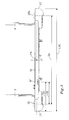
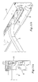
- Figure 1 shows a vehicle trailer 1 having a detachable light support bar 10 comprising a first and a second end 11, 12, and which is connected at the rear of the trailer 1.
- the illustrated vehicle trailer 1 comprises a frame 2 manufactured in a durable material such as plate steel.
- the frame 2 comprises a first and a second longitudinal bar 3, 4 which extends parallel with at least parts of the length of the vehicle trailer 1.
- Cross bars 6 provides for rigidity to the frame 2 of the vehicle trailer 1.
- a pair of wheels 7 enables the vehicle trailer 1 to be towed after a vehicle, such as a car (not shown).
- the vehicle trailer 1 is adapted to carry a boat, such as a small leisure craft. or a jet ski, for example. It should be noted that the detachable light support bar 10 can be used with other types of vehicle trailers than those adapted for trailing boats.
- the rear of the vehicle trailer 1 is that part of the vehicle trailer intended to face away from the vehicle, and the front of the vehicle trailer is that part adapted to be coupled to the vehicle for the purpose of towing the vehicle trailer.
- Figure 2-3 show parts of the rear of the vehicle trailer 1 in greater detail.
- the first and the second longitudinal bar 3, 4 each terminate with a connection site 8, 9 for the detachable light support bar 10.
- the connection sites 8, 9 will be described in greater detail below.
- the position of the connection sites 8, 9 are optionally adjustable length wise with respect to the first and the second longitudinal bars 3, 4, enabling the position of the detachable light support bar 10 to be adjusted to accommodate boats of different sizes on the trailer 1.
- the detachable light support bar 10 has a longitudinal extension L, as indicated in figure 3 . It can be formed by a housing or by an open structured material. Extruded aluminum profiles are advantageous and used in the shown embodiment. Other manufacturing materials can be sheet steel, or carbon fiber reinforced polymeric material for example. In cases where a sheet material is used, sensitive parts are preferably covered to prevent dirt and rubble to wear on sensitive parts.
- the detachable light support bar 10 is easy handle and can easily be removed from the vehicle trailer 1 by a user.
- the detachable light support bar 10 has at least one lock mechanism which is arranged in working cooperation with a release mechanism (not shown in figure 3 ) adapted to unlock the lock mechanism upon activation by a user at an activation point AP. When unlocked, the detachable light support bar 10 can be easily removed from the vehicle trailer 1 as will be described in greater detail herein.
- Figure 2 also shows alternative activation points AP2-AP4.
- the activation point AP is displaced a first distance D1 from the lock mechanism 20.
- the distance D1 is adapted to enable a user to activate the release mechanism with a first grip, and to remove the detachable light support bar 10 from the vehicle trailer 1 with the same first grip.
- a point of balance PB is indicated at a centre line C of the detachable light support bar 10, with respect to the longitudinal extension L of the detachable light support bar 10.
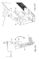
- Figure 4 shows the detachable light support bar 10 after its being detached from the trailer 1 by a user, leaving the first and the second connection site 8, 9 visible.
- detachable light support bar 10 and its function will be described in greater detail below. For the sake of simplicity, some features have been removed from the figures as compared with figure 1 and 2 for example.
- FIG. 5a-5b shows a connection site 8 of the vehicle trailer 1 in greater detail.
- the first and the second connection sites 8, 9 can be of the same type or of different type.
- detachable light support bar 10 comprises at least one lock mechanism 20.
- a first and a second lock mechanism 20, 20b (only one shown in figures 5a-5b ).
- the first and the second lock mechanisms 20, 20b are of the same type.
- the lock mechanism 20 cooperates with the connection site 8 to enable the detachable light support bar 10 to be releaseably connected in a secure manner. More specifically, the lock mechanism 20 is of a grip type lock, having a grip arrangement 20a comprising guiding portions 21, 22 adapted guide a lock pin 23 arranged at the connection site 8 into a slot formed between the guiding portions 21, 22, to secure the detachable light support bar 10 to the vehicle trailer 1.
- the guiding portions 21, 22 form together a substantially V formed, or cone formed opening, which is adapted to guide the lock pin 23 to a position in which it can be restrained, i.e. locked.
- the guiding portions 21, 22 are integrally formed with respect to each other in this embodiment.
- the lock mechanism can be provided with distinctly separated guiding portions, or guiding means, to guide the pin member 23 to the locked position. If the detachable light support bar 10 is slightly misaligned when being mounted to the vehicle trailer 1, the guiding means, in this case the tilting surfaces of the guiding portions 21, 22, will guide the lock pin 23 of the connection site 8 to a position in which it can be locked.
- the lock pin 23 of the connection site 8 is formed by a bolt protruding from a surface at the connection site 8.
- the grip arrangement 20a comprises a biasing member, adapted to impart a force component to displace a pivotable lock member PLM, to a position in which the pivotable lock member PLM is locked around the lock pin 23.
- the biasing member (not shown) can be a spring, an elastic material such a rubber, flexible metal sheet, or any other suitable material adapted to impart a force component to the pivotable lock member PLM.
- the arrow indicates suitable directions to remove or to mount the detachable light support bar 10 to the vehicle trailer 1 before it reaches the locked position.
- Figures 5c-5d shows the guiding portions 21, 22 in greater detail as well as the pivotable lock member PLM.
- figure 5c shows the lock mechanism in a locked position
- figure 5d shows the lock mechanism in a position ready to receive the pin member 23 of the connection site 8 of the vehicle trailer 1.
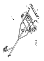
- Figure 6 shows the first end 11 of the detachable light support bar 10 with a view towards the vehicle trailer facing side.
- the lock mechanism 20 is arranged in working cooperation with a release mechanism 40.
- the release mechanism 40 is adapted to operate both the first and the second lock mechanism 20 (of which only the first in shown), it is however possible that the release mechanism is adapted to operate only one lock mechanism.
- the release mechanism 40 comprises a trigger button 41, which forms an activation point AP to activate the release mechanism 40.
- the trigger button could be a handle, a touch sensitive trigger surface or any other means for actuating the release mechanism.
- the trigger button 41 operates a displaceable pin member 42 connected to a slip point 43, in the form of a wheel 44.
- a spring 45 biases the trigger button 41 and the pin member 42 towards a position in which the release mechanism 40 is not operating on the lock mechanism 20 to unlock the lock mechanism 20.
- the displaceable pin member 42 is in working cooperation with an elongated element 47, in the form of a flexible string 48, such as a wire.
- the flexible string 48 extends between the each grip arrangement 20a of the first and the second lock mechanisms 20, 20b and is configured to, upon being tensioned, i.e. activated, open the pivotable lock member PLM of the lock mechanism 20, thus enabling the lock mechanism 20 to disengage the pin member 23 of the connection site 8 and the detachable light support bar 10 to be removed.
- the slip point 43 is displaced a distance Dpin, as is best illustrated by figure 7 .
- arrows can be seen illustrating the direction which the flexible string 48 travels as the pin member 42 is displaced downwards.
- the trigger button 41 has been pushed substantially into the interior of the detachable light support bar 20. During use, the interior can be covered to prevent dirt or other unwanted material to harm the mechanisms.
- the flexible string 48 can slip on a first and a second support point 49, 50 to transfer the downwardly motion, i.e. a vertical motion, of the pin member 42 to a horizontal motion of the flexible string 48.
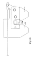
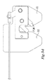
- Figure 8 shows the detachable light support bar 20 in the locked position and attached to the vehicle trailer 1 as seen from above. Parts have been removed to expose the lock mechanism 20 and the first and the second guiding portions 21, 22 of the grip arrangement. As can be see, the flexible string 48 is connected to a release peg 50, which when being displaced permits the first and the pivotable lock member PLM to open up and release the pin member 23, as seen in figure 9 .
- the release mechanism 40 When the release mechanism 40 is relieved from pressure by the users hand, i.e. the hand is removed from the trigger button 41, i.e. the activation point, the pin member 42 is returned to its original position, shown in figure 6 by the force imparted by the spring 45.
- the grip arrangement 20a of the lock mechanism 20 is now ready to receive the pin member 23 of the connection site 8 again at any appropriate time.
- a user can thus simply activate the release mechanism 40 at the activation point AP with a first grip by his first hand, and use his second hand to grasp a second grip on the detachable light support bar 10, to efficiently remove the detachable light support bar 10 in an easy manner.
- An electrical release mechanism is an option. Such release mechanism could operate so that after activation at the activation point AP, a signal is sent to an electrical motor in the lock mechanism so that the lock mechanism is unlocked.
- the detachable light support bar 10 comprises at least one support surface 60.
- the detachable light support bar 10 comprises a first and a second support surface (only one shown) arranged in the near proximity of the first and the second lock mechanisms 20.
- a corresponding surface 60c is arranged on the connection site 8, 9.
- the support surface 60 of the detachable light support bar 10 is formed by a support member 61 having a cross section which transcends through an arc shaped form from a first direction to a second direction substantially perpendicular to the first direction, as can be seen in figure 5a .
- the support member 61 has a proximal end 62 attached to the detachable light support bar 10 and a distal end distanced from the detachable light support bar 10.
- the distal end 63 of the support member 60 comprises a hook flange 64 adapted to cooperate with a similar flange on the connection site 8.
- the corresponding support surface 60c of the connection site 8 of the vehicle trailer 1 is formed by a support member 61c having a substantially similar form as the support member 60 of the detachable light support bar 10.
- the support member 60 of the detachable light support bar 10 is integrally formed parts of the detachable light support bar 10, but can of course be formed by a distinct component and attached to the detachable light support bar 10.
- Figure 5a-5b shows the detachable light support bar 10 and the connection site 8 after the detachable light support bar 10 has been detached therefrom.
- the support surface 60 of the detachable light support bar 10 is put to rest on the corresponding support surface 60c of the connection site 8 with a motion as indicated by the arrow in figure 5a .
- the motion is reversed.
- the rest position is shown in figures 10a-10b .
- a pivot axis P is formed about which the detachable light support bar 10 can pivot into the locked position at which the first and the second guiding potions 21, 22 guides the pin member 23 of the connection site 8 of the vehicle trailer 1, into a locked position.
- a user uses the leverage provided by the support surfaces 60, 60c to impart the necessary force to press the pin member 23 of the connection site 8 into the locked position between the first and the second guiding portions 21, 22 of the lock mechanism 20. Further, when removing the detachable light support bar 10, the detachable light support bar 10 can rest for a moment on the support surface helping the user to get a firm grip about the detachable light support bar 10 with one or two hands.
- the support surface 60 of the detachable light support bar 10 is thus advantageously separated a distance from the grip arrangement 20a of the lock mechanism 20 to enable leverage when displacing the detachable light support bar 10 from a rest position to a locked position.
- the detachable light support bar 10 in the embodiment shown in figures 10a-10b , pivots about a pivot axis P.
- the pivot axis P is substantially parallel with the longitudinal extension of the detachable light support bar 10, when the detachable light support bar 10 is mounted to the vehicle trailer 1. It is however plausible that the detachable light support bar 10 is configured to pivot about a pivot axis which is substantially perpendicular to the detachable light support bar 10, when the detachable light support bar 10 is mounted to the vehicle trailer 1.
- Such pivot axis is also referred to as a vertical axis herein.
- Figures 11a-11b shows how the detachable light support bar 10 has been pivoted into position with the connection site 8.
- the support member 61 is advantageously formed to cooperate with the connection site 8 in a manner so that the detachable light support bar 10 cannot accidentally disconnect from the vehicle trailer 1. If the release mechanism 20 is activated by mistake, the detachable light support bar 10 will not be fully released and dropped to the ground. The detachable light support bar 10 will simply pivot about the pivot axis P, as indicated by the arc formed arrow in figure 12a , and hang from the connection site 8 by means of the hook flange 64 at the distal end 63 of the support member 60.
Landscapes
- Engineering & Computer Science (AREA)
- Mechanical Engineering (AREA)
- Lighting Device Outwards From Vehicle And Optical Signal (AREA)
Claims (13)
- Eine abnehmbare Lichtträgerstange (10) für einen Fahrzeuganhänger (1), wobei die abnehmbare Lichtträgerstange (10) ein erstes und ein zweites Ende (11, 12) aufweist sowie eine längs gerichtete Erstreckung (L) zwischen diesen beiden, wobei die abnehmbare Lichtträgerstange (10) mindestens einen Verriegelungsmechanismus (20, 20b) umfasst, um die abnehmbare Lichtträgerstange (10) entriegelbar an dem Fahrzeuganhänger (1) zu verriegeln,
wobei der Verriegelungsmechanismus (20, 20b) so angelegt ist, dass er mit mindestens einem Entriegelungsmechanismus (40) zusammenwirkt, wobei der mindestens eine Entriegelungsmechanismus (40) dafür ausgelegt ist, den mindestens einen Verriegelungsmechanismus (20, 20b) auf das Betätigen eines Aktivierungspunktes (AP) durch einen Nutzer hin zu entriegeln, wodurch das Entfernen der abnehmbaren Lichtträgerstange (10) von dem Fahrzeuganhänger (1) zugelassen wird,
dadurch gekennzeichnet, dass
der Aktivierungspunkt (AP) an der abnehmbaren Lichtträgerstange (10) angeordnet ist und um einen entlang der längs gerichteten Erstreckung (L) der abnehmbaren Lichtträgerstange (10) gemessenen Abstand (D1) von dem mindestens einen Verriegelungsmechanismus (20, 20b) versetzt ist, wodurch der Nutzer in die Lage versetzt wird, den Entriegelungsmechanismus (40) mit einem ersten Griff zu betätigen und die abnehmbare Lichtträgerstange (10) mittels dieses ersten Griffs von dem Fahrzeuganhänger (1) zu entfernen. - Die abnehmbare Lichtträgerstange (10) nach Anspruch 1, worin das erste und das zweite Ende (11, 12) der abnehmbaren Lichtträgerstange (10) durch einen ersten Abstand (D2) getrennt sind, und worin der Aktivierungspunkt (AP) in einem zweiten Abstand (D3) von dem ersten Ende (11) der abnehmbaren Lichtträgerstange (10) angeordnet ist, wobei der zweite Abstand (D3) ca. 10 bis 50 % des ersten Abstands (D2) beträgt.
- Die abnehmbare Lichtträgerstange (10) nach einem der vorangehenden Ansprüche, worin die abnehmbare Lichtträgerstange (10) einen Balance-Punkt (PB) umfasst, der zwischen dem ersten und dem zweiten Ende (11, 12) der abnehmbaren Lichtträgerstange (10) angeordnet ist, und worin der Aktivierungspunkt (AP) zwischen dem Balance-Punkt (PB) und dem mindestens einen Verriegelungsmechanismus (20) angeordnet ist.
- Die abnehmbare Lichtträgerstange (10) nach einem der vorangehenden Ansprüche, worin die abnehmbare Lichtträgerstange (10) einen ersten und einen zweiten Verriegelungsmechanismus (20, 20b) umfasst, die so angelegt sind, dass sie mit einer ersten und einer zweiten Verbindungsstelle (8, 9) an dem Fahrzeuganhänger (1) zusammenwirken, und worin der Entriegelungsmechanismus (40) so angelegt ist, dass er mit dem ersten und dem zweiten Verriegelungsmechanismus (20, 20b) zusammenwirkt, so dass auf die Betätigung des Entriegelungsmechanismus (40) hin der erste und der zweite Verriegelungsmechanismus (20, 20b) entriegelt werden.
- Die abnehmbare Lichtträgerstange (10) nach Anspruch 4, worin der erste und der zweite Verriegelungsmechanismus (20, 20b) gleichzeitig auf die Betätigung des Entriegelungsmechanismus (40) hin entriegelt werden.
- Die abnehmbare Lichtträgerstange (10) nach Anspruch 4 oder 5, worin der Aktivierungspunkt (AP) zwischen dem ersten und dem zweiten Verriegelungsmechanismus (20, 20b), bezogen auf die längs gerichtete Erstreckung (L) der abnehmbaren Lichtträgerstange (10), angeordnet ist.
- Die abnehmbare Lichtträgerstange (10) nach Anspruch 6, worin der erste und der zweite Verriegelungsmechanismus (20, 20b) durch einen dritten Abstand (D4) getrennt sind, gemessen entlang der längs gerichteten Erstreckung (L) der abnehmbaren Lichtträgerstange (10), und worin der Aktivierungspunkt (AP) so angeordnet ist, dass der Abstand (D1) von dem ersten Verriegelungsmechanismus (20), gemessen entlang der längs gerichteten Erstreckung (L) der abnehmbaren Lichtträgerstange (10), etwa 10 bis 50 % des dritten Abstands (D4) beträgt.
- Die abnehmbare Lichtträgerstange (10) nach einem der vorangehenden Ansprüche, worin die abnehmbare Lichtträgerstange (10) mindestens eine Lagerfläche (60) umfasst, welche dafür ausgelegt ist, mit einer entsprechenden Fläche (60c) des Fahrzeuganhängers (1) zusammen zu wirken, wobei die Lagerfläche (60) der abnehmbaren Lichtträgerstange (10) dafür ausgelegt ist, das Positionieren der abnehmbaren Lichtträgerstange (10) in einer Ruheposition zu ermöglichen, bevor diese in eine verriegelte Position gebracht wird, oder direkt, oder nachfolgend, nachdem sie entriegelt worden ist.
- Die abnehmbare Lichtträgerstange (10) nach Anspruch 8, worin die Lagerfläche (60) der abnehmbaren Lichtträgerstange (10) die abnehmbare Lichtträgerstange (10) gemeinsam mit der entsprechenden Fläche (60c) des Fahrzeuganhängers (1) mit einer Schwenkachse (P) versieht, wodurch es der abnehmbaren Lichtträgerstange (10) ermöglicht wird, zwischen der Ruheposition und der verriegelten Position um die Schwenkachse (P) herum geschwenkt zu werden.
- Die abnehmbare Lichtträgerstange (10) nach Anspruch 9, worin sich die Schwenkachse (P) im Wesentlichen parallel zu der längsgerichteten Erstreckung (L) der abnehmbaren Lichtträgerstange (10) erstreckt, wenn die abnehmbare Lichtträgerstange (10) montiert und an dem Fahrzeuganhänger (1) verriegelt ist.
- Ein Fahrzeuganhänger (1), umfassend eine abnehmbare Lichtträgerstange (10) nach einem der vorangehenden Ansprüche.
- Ein Verfahren zum Entfernen einer abnehmbaren Lichtträgerstange (10) nach einem der Ansprüche 1 bis 10 von einem Fahrzeuganhänger (1)
dadurch gekennzeichnet, dass
das Verfahren folgende Schritte umfasst:- Betätigen eines Entriegelungsmechanismus' (40) an einem Aktivierungspunkt (AP), um die abnehmbare Lichtträgerstange (10) von einer Verbindungsstelle (8, 9) des Fahrzeuganhängers (1) mit einem ersten Griff zu entriegeln,- Entfernen der abnehmbaren Lichtträgerstange (10), indem dieser erste Griff benutzt wird. - Das Verfahren nach Anspruch 12, worin das Verfahren des Weiteren folgenden Schritt umfasst:- gleichzeitiges Entriegeln von mindestens zwei Schließmechanismen (20, 20b) auf das Betätigen des Entriegelungsmechanismus' (40) hin.
Priority Applications (3)
| Application Number | Priority Date | Filing Date | Title |
|---|---|---|---|
| PL11187892T PL2589512T3 (pl) | 2011-11-04 | 2011-11-04 | Pręt do podtrzymywania świateł dla przyczepy pojazdu |
| EP11187892.2A EP2589512B1 (de) | 2011-11-04 | 2011-11-04 | Lichtträgerstange für einen Fahrzeuganhänger |
| DK11187892.2T DK2589512T3 (en) | 2011-11-04 | 2011-11-04 | Light bar for vehicle trailer |
Applications Claiming Priority (1)
| Application Number | Priority Date | Filing Date | Title |
|---|---|---|---|
| EP11187892.2A EP2589512B1 (de) | 2011-11-04 | 2011-11-04 | Lichtträgerstange für einen Fahrzeuganhänger |
Publications (2)
| Publication Number | Publication Date |
|---|---|
| EP2589512A1 EP2589512A1 (de) | 2013-05-08 |
| EP2589512B1 true EP2589512B1 (de) | 2015-02-11 |
Family
ID=44905693
Family Applications (1)
| Application Number | Title | Priority Date | Filing Date |
|---|---|---|---|
| EP11187892.2A Not-in-force EP2589512B1 (de) | 2011-11-04 | 2011-11-04 | Lichtträgerstange für einen Fahrzeuganhänger |
Country Status (3)
| Country | Link |
|---|---|
| EP (1) | EP2589512B1 (de) |
| DK (1) | DK2589512T3 (de) |
| PL (1) | PL2589512T3 (de) |
Cited By (1)
| Publication number | Priority date | Publication date | Assignee | Title |
|---|---|---|---|---|
| WO2020106846A1 (en) * | 2018-11-21 | 2020-05-28 | Magna International Inc. | Modular cargo platform for automotive applications |
Families Citing this family (2)
| Publication number | Priority date | Publication date | Assignee | Title |
|---|---|---|---|---|
| US11511659B2 (en) | 2021-03-18 | 2022-11-29 | Ford Global Technologies, Llc | Detachable lighting assembly for a vehicle |
| PL4331914T3 (pl) * | 2022-09-02 | 2025-10-06 | Epsilon Kran Gmbh. | Urządzenie sygnalizacyjne do wystającego ładunku pojazdu |
Family Cites Families (4)
| Publication number | Priority date | Publication date | Assignee | Title |
|---|---|---|---|---|
| US3691366A (en) | 1970-09-23 | 1972-09-12 | Philip M Spreuer | Telescoping light bar |
| US4286309A (en) * | 1980-02-07 | 1981-08-25 | Clarence Rasinski | Detachable vehicle lighting fixture |
| US4422664A (en) | 1981-06-16 | 1983-12-27 | Sebert E. Reese, II | Boat trailer fender, lamp and license plate support |
| US20110090072A1 (en) * | 2009-10-20 | 2011-04-21 | Paul Haldeman | Auxiliary tow lighting with versatile gripping apparatus and method |
-
2011
- 2011-11-04 EP EP11187892.2A patent/EP2589512B1/de not_active Not-in-force
- 2011-11-04 DK DK11187892.2T patent/DK2589512T3/en active
- 2011-11-04 PL PL11187892T patent/PL2589512T3/pl unknown
Cited By (2)
| Publication number | Priority date | Publication date | Assignee | Title |
|---|---|---|---|---|
| WO2020106846A1 (en) * | 2018-11-21 | 2020-05-28 | Magna International Inc. | Modular cargo platform for automotive applications |
| US12017620B2 (en) | 2018-11-21 | 2024-06-25 | Magna International Inc. | Modular cargo platform for automotive applications |
Also Published As
| Publication number | Publication date |
|---|---|
| PL2589512T3 (pl) | 2015-10-30 |
| EP2589512A1 (de) | 2013-05-08 |
| DK2589512T3 (en) | 2015-05-11 |
Similar Documents
| Publication | Publication Date | Title |
|---|---|---|
| US7845711B2 (en) | Quick-attach/detach cab for vehicle | |
| US7263750B2 (en) | Buckle assembly having single release for multiple belt connectors | |
| US20130062385A1 (en) | Bicycle-Carrier Device For Motor Vehicles | |
| EP2589512B1 (de) | Lichtträgerstange für einen Fahrzeuganhänger | |
| US20190061629A1 (en) | Safety ladder and retaining system for trailer | |
| EP3060432B1 (de) | Anker oder lastträger für eine fahrraddurchgangsachse | |
| EP3455092B1 (de) | Stufenplattformvorrichtung zum anschluss an eine anhängerkupplungskugel | |
| US8152193B2 (en) | Watercraft trailer | |
| US20040108349A1 (en) | Snowboard rack for snowmobiles | |
| CN105793148B (zh) | 用于机动两轮车的行李系统 | |
| SE1250947A1 (sv) | Släpfordon för transport av en rullstolsburen person | |
| US8955453B2 (en) | Personal land-sea transport apparatus | |
| US20180334000A1 (en) | Amphibious boats | |
| US8016313B2 (en) | Tow rack | |
| US20150246644A1 (en) | Extendable Fork Forward Bicycle Carrier | |
| US10780854B1 (en) | Push bumper integrated with bike rack | |
| EP2159106A1 (de) | An ein Fahrzeug kuppelbarer Lastenträger, zum Beispiel ein Fahrradträger | |
| US20120318597A1 (en) | Portable Winch Stow Plate | |
| JP5900832B2 (ja) | 電動牽引車 | |
| RU2532310C2 (ru) | Упорный клин для автомобилей | |
| US7032906B1 (en) | Towing apparatus for rescue toboggan | |
| AU2012100241B4 (en) | Boat trolley | |
| US20070187923A1 (en) | Equalizer tandem pin puller | |
| KR200201747Y1 (ko) | 탈착식 고무링이 장착된 차륜 및 소형운반구 바퀴의 휠 | |
| AU2019200551A1 (en) | Trailer reversing apparatus |
Legal Events
| Date | Code | Title | Description |
|---|---|---|---|
| PUAI | Public reference made under article 153(3) epc to a published international application that has entered the european phase |
Free format text: ORIGINAL CODE: 0009012 |
|
| AK | Designated contracting states |
Kind code of ref document: A1 Designated state(s): AL AT BE BG CH CY CZ DE DK EE ES FI FR GB GR HR HU IE IS IT LI LT LU LV MC MK MT NL NO PL PT RO RS SE SI SK SM TR |
|
| AX | Request for extension of the european patent |
Extension state: BA ME |
|
| 17P | Request for examination filed |
Effective date: 20131021 |
|
| RBV | Designated contracting states (corrected) |
Designated state(s): AL AT BE BG CH CY CZ DE DK EE ES FI FR GB GR HR HU IE IS IT LI LT LU LV MC MK MT NL NO PL PT RO RS SE SI SK SM TR |
|
| GRAP | Despatch of communication of intention to grant a patent |
Free format text: ORIGINAL CODE: EPIDOSNIGR1 |
|
| INTG | Intention to grant announced |
Effective date: 20140328 |
|
| GRAS | Grant fee paid |
Free format text: ORIGINAL CODE: EPIDOSNIGR3 |
|
| GRAP | Despatch of communication of intention to grant a patent |
Free format text: ORIGINAL CODE: EPIDOSNIGR1 |
|
| INTG | Intention to grant announced |
Effective date: 20140901 |
|
| RAP1 | Party data changed (applicant data changed or rights of an application transferred) |
Owner name: BRENDERUP AB |
|
| GRAA | (expected) grant |
Free format text: ORIGINAL CODE: 0009210 |
|
| AK | Designated contracting states |
Kind code of ref document: B1 Designated state(s): AL AT BE BG CH CY CZ DE DK EE ES FI FR GB GR HR HU IE IS IT LI LT LU LV MC MK MT NL NO PL PT RO RS SE SI SK SM TR |
|
| REG | Reference to a national code |
Ref country code: GB Ref legal event code: FG4D |
|
| REG | Reference to a national code |
Ref country code: CH Ref legal event code: EP |
|
| REG | Reference to a national code |
Ref country code: IE Ref legal event code: FG4D |
|
| REG | Reference to a national code |
Ref country code: AT Ref legal event code: REF Ref document number: 709809 Country of ref document: AT Kind code of ref document: T Effective date: 20150315 |
|
| REG | Reference to a national code |
Ref country code: DE Ref legal event code: R096 Ref document number: 602011013610 Country of ref document: DE Effective date: 20150326 |
|
| REG | Reference to a national code |
Ref country code: DK Ref legal event code: T3 Effective date: 20150508 |
|
| REG | Reference to a national code |
Ref country code: SE Ref legal event code: TRGR |
|
| REG | Reference to a national code |
Ref country code: NL Ref legal event code: VDEP Effective date: 20150211 |
|
| REG | Reference to a national code |
Ref country code: NO Ref legal event code: T2 Effective date: 20150211 |
|
| REG | Reference to a national code |
Ref country code: AT Ref legal event code: MK05 Ref document number: 709809 Country of ref document: AT Kind code of ref document: T Effective date: 20150211 |
|
| REG | Reference to a national code |
Ref country code: LT Ref legal event code: MG4D |
|
| PG25 | Lapsed in a contracting state [announced via postgrant information from national office to epo] |
Ref country code: FI Free format text: LAPSE BECAUSE OF FAILURE TO SUBMIT A TRANSLATION OF THE DESCRIPTION OR TO PAY THE FEE WITHIN THE PRESCRIBED TIME-LIMIT Effective date: 20150211 Ref country code: HR Free format text: LAPSE BECAUSE OF FAILURE TO SUBMIT A TRANSLATION OF THE DESCRIPTION OR TO PAY THE FEE WITHIN THE PRESCRIBED TIME-LIMIT Effective date: 20150211 Ref country code: ES Free format text: LAPSE BECAUSE OF FAILURE TO SUBMIT A TRANSLATION OF THE DESCRIPTION OR TO PAY THE FEE WITHIN THE PRESCRIBED TIME-LIMIT Effective date: 20150211 Ref country code: LT Free format text: LAPSE BECAUSE OF FAILURE TO SUBMIT A TRANSLATION OF THE DESCRIPTION OR TO PAY THE FEE WITHIN THE PRESCRIBED TIME-LIMIT Effective date: 20150211 |
|
| PG25 | Lapsed in a contracting state [announced via postgrant information from national office to epo] |
Ref country code: GR Free format text: LAPSE BECAUSE OF FAILURE TO SUBMIT A TRANSLATION OF THE DESCRIPTION OR TO PAY THE FEE WITHIN THE PRESCRIBED TIME-LIMIT Effective date: 20150512 Ref country code: LV Free format text: LAPSE BECAUSE OF FAILURE TO SUBMIT A TRANSLATION OF THE DESCRIPTION OR TO PAY THE FEE WITHIN THE PRESCRIBED TIME-LIMIT Effective date: 20150211 Ref country code: RS Free format text: LAPSE BECAUSE OF FAILURE TO SUBMIT A TRANSLATION OF THE DESCRIPTION OR TO PAY THE FEE WITHIN THE PRESCRIBED TIME-LIMIT Effective date: 20150211 Ref country code: NL Free format text: LAPSE BECAUSE OF FAILURE TO SUBMIT A TRANSLATION OF THE DESCRIPTION OR TO PAY THE FEE WITHIN THE PRESCRIBED TIME-LIMIT Effective date: 20150211 Ref country code: IS Free format text: LAPSE BECAUSE OF FAILURE TO SUBMIT A TRANSLATION OF THE DESCRIPTION OR TO PAY THE FEE WITHIN THE PRESCRIBED TIME-LIMIT Effective date: 20150611 Ref country code: AT Free format text: LAPSE BECAUSE OF FAILURE TO SUBMIT A TRANSLATION OF THE DESCRIPTION OR TO PAY THE FEE WITHIN THE PRESCRIBED TIME-LIMIT Effective date: 20150211 |
|
| PG25 | Lapsed in a contracting state [announced via postgrant information from national office to epo] |
Ref country code: SK Free format text: LAPSE BECAUSE OF FAILURE TO SUBMIT A TRANSLATION OF THE DESCRIPTION OR TO PAY THE FEE WITHIN THE PRESCRIBED TIME-LIMIT Effective date: 20150211 Ref country code: CZ Free format text: LAPSE BECAUSE OF FAILURE TO SUBMIT A TRANSLATION OF THE DESCRIPTION OR TO PAY THE FEE WITHIN THE PRESCRIBED TIME-LIMIT Effective date: 20150211 Ref country code: EE Free format text: LAPSE BECAUSE OF FAILURE TO SUBMIT A TRANSLATION OF THE DESCRIPTION OR TO PAY THE FEE WITHIN THE PRESCRIBED TIME-LIMIT Effective date: 20150211 Ref country code: RO Free format text: LAPSE BECAUSE OF FAILURE TO SUBMIT A TRANSLATION OF THE DESCRIPTION OR TO PAY THE FEE WITHIN THE PRESCRIBED TIME-LIMIT Effective date: 20150211 |
|
| REG | Reference to a national code |
Ref country code: PL Ref legal event code: T3 |
|
| REG | Reference to a national code |
Ref country code: FR Ref legal event code: PLFP Year of fee payment: 5 |
|
| REG | Reference to a national code |
Ref country code: DE Ref legal event code: R097 Ref document number: 602011013610 Country of ref document: DE |
|
| PLBE | No opposition filed within time limit |
Free format text: ORIGINAL CODE: 0009261 |
|
| STAA | Information on the status of an ep patent application or granted ep patent |
Free format text: STATUS: NO OPPOSITION FILED WITHIN TIME LIMIT |
|
| PG25 | Lapsed in a contracting state [announced via postgrant information from national office to epo] |
Ref country code: IT Free format text: LAPSE BECAUSE OF FAILURE TO SUBMIT A TRANSLATION OF THE DESCRIPTION OR TO PAY THE FEE WITHIN THE PRESCRIBED TIME-LIMIT Effective date: 20150211 |
|
| 26N | No opposition filed |
Effective date: 20151112 |
|
| PG25 | Lapsed in a contracting state [announced via postgrant information from national office to epo] |
Ref country code: SI Free format text: LAPSE BECAUSE OF FAILURE TO SUBMIT A TRANSLATION OF THE DESCRIPTION OR TO PAY THE FEE WITHIN THE PRESCRIBED TIME-LIMIT Effective date: 20150211 |
|
| PG25 | Lapsed in a contracting state [announced via postgrant information from national office to epo] |
Ref country code: BE Free format text: LAPSE BECAUSE OF FAILURE TO SUBMIT A TRANSLATION OF THE DESCRIPTION OR TO PAY THE FEE WITHIN THE PRESCRIBED TIME-LIMIT Effective date: 20150211 |
|
| PG25 | Lapsed in a contracting state [announced via postgrant information from national office to epo] |
Ref country code: LU Free format text: LAPSE BECAUSE OF FAILURE TO SUBMIT A TRANSLATION OF THE DESCRIPTION OR TO PAY THE FEE WITHIN THE PRESCRIBED TIME-LIMIT Effective date: 20151104 Ref country code: MC Free format text: LAPSE BECAUSE OF FAILURE TO SUBMIT A TRANSLATION OF THE DESCRIPTION OR TO PAY THE FEE WITHIN THE PRESCRIBED TIME-LIMIT Effective date: 20150211 |
|
| REG | Reference to a national code |
Ref country code: CH Ref legal event code: PL |
|
| GBPC | Gb: european patent ceased through non-payment of renewal fee |
Effective date: 20151104 |
|
| PG25 | Lapsed in a contracting state [announced via postgrant information from national office to epo] |
Ref country code: CH Free format text: LAPSE BECAUSE OF NON-PAYMENT OF DUE FEES Effective date: 20151130 Ref country code: LI Free format text: LAPSE BECAUSE OF NON-PAYMENT OF DUE FEES Effective date: 20151130 |
|
| REG | Reference to a national code |
Ref country code: IE Ref legal event code: MM4A |
|
| REG | Reference to a national code |
Ref country code: FR Ref legal event code: PLFP Year of fee payment: 6 |
|
| PG25 | Lapsed in a contracting state [announced via postgrant information from national office to epo] |
Ref country code: GB Free format text: LAPSE BECAUSE OF NON-PAYMENT OF DUE FEES Effective date: 20151104 Ref country code: IE Free format text: LAPSE BECAUSE OF NON-PAYMENT OF DUE FEES Effective date: 20151104 |
|
| PG25 | Lapsed in a contracting state [announced via postgrant information from national office to epo] |
Ref country code: SM Free format text: LAPSE BECAUSE OF FAILURE TO SUBMIT A TRANSLATION OF THE DESCRIPTION OR TO PAY THE FEE WITHIN THE PRESCRIBED TIME-LIMIT Effective date: 20150211 Ref country code: HU Free format text: LAPSE BECAUSE OF FAILURE TO SUBMIT A TRANSLATION OF THE DESCRIPTION OR TO PAY THE FEE WITHIN THE PRESCRIBED TIME-LIMIT; INVALID AB INITIO Effective date: 20111104 Ref country code: BG Free format text: LAPSE BECAUSE OF FAILURE TO SUBMIT A TRANSLATION OF THE DESCRIPTION OR TO PAY THE FEE WITHIN THE PRESCRIBED TIME-LIMIT Effective date: 20150211 |
|
| PG25 | Lapsed in a contracting state [announced via postgrant information from national office to epo] |
Ref country code: CY Free format text: LAPSE BECAUSE OF FAILURE TO SUBMIT A TRANSLATION OF THE DESCRIPTION OR TO PAY THE FEE WITHIN THE PRESCRIBED TIME-LIMIT Effective date: 20150211 |
|
| PG25 | Lapsed in a contracting state [announced via postgrant information from national office to epo] |
Ref country code: MT Free format text: LAPSE BECAUSE OF FAILURE TO SUBMIT A TRANSLATION OF THE DESCRIPTION OR TO PAY THE FEE WITHIN THE PRESCRIBED TIME-LIMIT Effective date: 20150211 |
|
| REG | Reference to a national code |
Ref country code: FR Ref legal event code: PLFP Year of fee payment: 7 |
|
| PG25 | Lapsed in a contracting state [announced via postgrant information from national office to epo] |
Ref country code: PT Free format text: LAPSE BECAUSE OF FAILURE TO SUBMIT A TRANSLATION OF THE DESCRIPTION OR TO PAY THE FEE WITHIN THE PRESCRIBED TIME-LIMIT Effective date: 20150211 Ref country code: MK Free format text: LAPSE BECAUSE OF FAILURE TO SUBMIT A TRANSLATION OF THE DESCRIPTION OR TO PAY THE FEE WITHIN THE PRESCRIBED TIME-LIMIT Effective date: 20150211 Ref country code: TR Free format text: LAPSE BECAUSE OF FAILURE TO SUBMIT A TRANSLATION OF THE DESCRIPTION OR TO PAY THE FEE WITHIN THE PRESCRIBED TIME-LIMIT Effective date: 20150211 |
|
| REG | Reference to a national code |
Ref country code: FR Ref legal event code: PLFP Year of fee payment: 8 |
|
| PG25 | Lapsed in a contracting state [announced via postgrant information from national office to epo] |
Ref country code: AL Free format text: LAPSE BECAUSE OF FAILURE TO SUBMIT A TRANSLATION OF THE DESCRIPTION OR TO PAY THE FEE WITHIN THE PRESCRIBED TIME-LIMIT Effective date: 20150211 |
|
| PGFP | Annual fee paid to national office [announced via postgrant information from national office to epo] |
Ref country code: DE Payment date: 20191017 Year of fee payment: 9 Ref country code: NO Payment date: 20191017 Year of fee payment: 9 Ref country code: SE Payment date: 20191015 Year of fee payment: 9 |
|
| PGFP | Annual fee paid to national office [announced via postgrant information from national office to epo] |
Ref country code: DK Payment date: 20191018 Year of fee payment: 9 Ref country code: PL Payment date: 20191001 Year of fee payment: 9 Ref country code: FR Payment date: 20191017 Year of fee payment: 9 |
|
| REG | Reference to a national code |
Ref country code: DE Ref legal event code: R119 Ref document number: 602011013610 Country of ref document: DE |
|
| REG | Reference to a national code |
Ref country code: NO Ref legal event code: MMEP Ref country code: DK Ref legal event code: EBP Effective date: 20201130 |
|
| REG | Reference to a national code |
Ref country code: SE Ref legal event code: EUG |
|
| PG25 | Lapsed in a contracting state [announced via postgrant information from national office to epo] |
Ref country code: NO Free format text: LAPSE BECAUSE OF NON-PAYMENT OF DUE FEES Effective date: 20201130 |
|
| PG25 | Lapsed in a contracting state [announced via postgrant information from national office to epo] |
Ref country code: SE Free format text: LAPSE BECAUSE OF NON-PAYMENT OF DUE FEES Effective date: 20201105 |
|
| PG25 | Lapsed in a contracting state [announced via postgrant information from national office to epo] |
Ref country code: FR Free format text: LAPSE BECAUSE OF NON-PAYMENT OF DUE FEES Effective date: 20201130 |
|
| PG25 | Lapsed in a contracting state [announced via postgrant information from national office to epo] |
Ref country code: DE Free format text: LAPSE BECAUSE OF NON-PAYMENT OF DUE FEES Effective date: 20210601 Ref country code: DK Free format text: LAPSE BECAUSE OF NON-PAYMENT OF DUE FEES Effective date: 20201130 |
|
| PG25 | Lapsed in a contracting state [announced via postgrant information from national office to epo] |
Ref country code: PL Free format text: LAPSE BECAUSE OF NON-PAYMENT OF DUE FEES Effective date: 20201104 |