EP2588752B1 - Wind turbine system for detection of blade icing - Google Patents
Wind turbine system for detection of blade icing Download PDFInfo
- Publication number
- EP2588752B1 EP2588752B1 EP11729051.0A EP11729051A EP2588752B1 EP 2588752 B1 EP2588752 B1 EP 2588752B1 EP 11729051 A EP11729051 A EP 11729051A EP 2588752 B1 EP2588752 B1 EP 2588752B1
- Authority
- EP
- European Patent Office
- Prior art keywords
- blade
- signal
- excitation
- wind turbine
- vibration
- Prior art date
- Legal status (The legal status is an assumption and is not a legal conclusion. Google has not performed a legal analysis and makes no representation as to the accuracy of the status listed.)
- Active
Links
- 238000001514 detection method Methods 0.000 title claims description 32
- 230000005284 excitation Effects 0.000 claims description 93
- 238000011068 loading method Methods 0.000 claims description 41
- 238000001228 spectrum Methods 0.000 claims description 30
- 230000006870 function Effects 0.000 claims description 28
- 238000000034 method Methods 0.000 claims description 17
- 238000012545 processing Methods 0.000 claims description 14
- 230000008859 change Effects 0.000 claims description 10
- 230000001360 synchronised effect Effects 0.000 claims description 4
- 230000003247 decreasing effect Effects 0.000 claims description 3
- 230000004044 response Effects 0.000 description 28
- 230000001133 acceleration Effects 0.000 description 8
- 238000004519 manufacturing process Methods 0.000 description 6
- 230000033001 locomotion Effects 0.000 description 5
- 230000005540 biological transmission Effects 0.000 description 4
- 230000007423 decrease Effects 0.000 description 4
- 238000005259 measurement Methods 0.000 description 4
- 238000012544 monitoring process Methods 0.000 description 4
- 230000008901 benefit Effects 0.000 description 3
- 230000006378 damage Effects 0.000 description 3
- 238000010438 heat treatment Methods 0.000 description 3
- 238000013178 mathematical model Methods 0.000 description 3
- 238000005070 sampling Methods 0.000 description 3
- 230000009471 action Effects 0.000 description 2
- 230000003111 delayed effect Effects 0.000 description 2
- 238000009826 distribution Methods 0.000 description 2
- 239000000835 fiber Substances 0.000 description 2
- 238000009434 installation Methods 0.000 description 2
- 150000003839 salts Chemical class 0.000 description 2
- 230000003213 activating effect Effects 0.000 description 1
- 230000003542 behavioural effect Effects 0.000 description 1
- 230000015572 biosynthetic process Effects 0.000 description 1
- 230000015556 catabolic process Effects 0.000 description 1
- 239000002131 composite material Substances 0.000 description 1
- 238000012790 confirmation Methods 0.000 description 1
- 238000010276 construction Methods 0.000 description 1
- 230000001419 dependent effect Effects 0.000 description 1
- 238000006073 displacement reaction Methods 0.000 description 1
- 230000009977 dual effect Effects 0.000 description 1
- 238000011156 evaluation Methods 0.000 description 1
- 230000006872 improvement Effects 0.000 description 1
- 230000000670 limiting effect Effects 0.000 description 1
- 230000004807 localization Effects 0.000 description 1
- 238000003062 neural network model Methods 0.000 description 1
- 238000005457 optimization Methods 0.000 description 1
- 238000001556 precipitation Methods 0.000 description 1
- 230000002829 reductive effect Effects 0.000 description 1
- 239000004576 sand Substances 0.000 description 1
- 230000011664 signaling Effects 0.000 description 1
- 238000004088 simulation Methods 0.000 description 1
- 230000003595 spectral effect Effects 0.000 description 1
- 230000003068 static effect Effects 0.000 description 1
- 238000003860 storage Methods 0.000 description 1
- 230000036962 time dependent Effects 0.000 description 1
- 230000009466 transformation Effects 0.000 description 1
- 238000000844 transformation Methods 0.000 description 1
- 238000001845 vibrational spectrum Methods 0.000 description 1
- XLYOFNOQVPJJNP-UHFFFAOYSA-N water Substances O XLYOFNOQVPJJNP-UHFFFAOYSA-N 0.000 description 1
Images


Classifications
-
- F—MECHANICAL ENGINEERING; LIGHTING; HEATING; WEAPONS; BLASTING
- F01—MACHINES OR ENGINES IN GENERAL; ENGINE PLANTS IN GENERAL; STEAM ENGINES
- F01D—NON-POSITIVE DISPLACEMENT MACHINES OR ENGINES, e.g. STEAM TURBINES
- F01D25/00—Component parts, details, or accessories, not provided for in, or of interest apart from, other groups
-
- F—MECHANICAL ENGINEERING; LIGHTING; HEATING; WEAPONS; BLASTING
- F03—MACHINES OR ENGINES FOR LIQUIDS; WIND, SPRING, OR WEIGHT MOTORS; PRODUCING MECHANICAL POWER OR A REACTIVE PROPULSIVE THRUST, NOT OTHERWISE PROVIDED FOR
- F03D—WIND MOTORS
- F03D7/00—Controlling wind motors
- F03D7/02—Controlling wind motors the wind motors having rotation axis substantially parallel to the air flow entering the rotor
- F03D7/04—Automatic control; Regulation
- F03D7/042—Automatic control; Regulation by means of an electrical or electronic controller
-
- F—MECHANICAL ENGINEERING; LIGHTING; HEATING; WEAPONS; BLASTING
- F03—MACHINES OR ENGINES FOR LIQUIDS; WIND, SPRING, OR WEIGHT MOTORS; PRODUCING MECHANICAL POWER OR A REACTIVE PROPULSIVE THRUST, NOT OTHERWISE PROVIDED FOR
- F03D—WIND MOTORS
- F03D17/00—Monitoring or testing of wind motors, e.g. diagnostics
-
- F—MECHANICAL ENGINEERING; LIGHTING; HEATING; WEAPONS; BLASTING
- F03—MACHINES OR ENGINES FOR LIQUIDS; WIND, SPRING, OR WEIGHT MOTORS; PRODUCING MECHANICAL POWER OR A REACTIVE PROPULSIVE THRUST, NOT OTHERWISE PROVIDED FOR
- F03D—WIND MOTORS
- F03D80/00—Details, components or accessories not provided for in groups F03D1/00 - F03D17/00
- F03D80/40—Ice detection; De-icing means
-
- F—MECHANICAL ENGINEERING; LIGHTING; HEATING; WEAPONS; BLASTING
- F05—INDEXING SCHEMES RELATING TO ENGINES OR PUMPS IN VARIOUS SUBCLASSES OF CLASSES F01-F04
- F05B—INDEXING SCHEME RELATING TO WIND, SPRING, WEIGHT, INERTIA OR LIKE MOTORS, TO MACHINES OR ENGINES FOR LIQUIDS COVERED BY SUBCLASSES F03B, F03D AND F03G
- F05B2260/00—Function
- F05B2260/80—Diagnostics
-
- F—MECHANICAL ENGINEERING; LIGHTING; HEATING; WEAPONS; BLASTING
- F05—INDEXING SCHEMES RELATING TO ENGINES OR PUMPS IN VARIOUS SUBCLASSES OF CLASSES F01-F04
- F05B—INDEXING SCHEME RELATING TO WIND, SPRING, WEIGHT, INERTIA OR LIKE MOTORS, TO MACHINES OR ENGINES FOR LIQUIDS COVERED BY SUBCLASSES F03B, F03D AND F03G
- F05B2260/00—Function
- F05B2260/96—Preventing, counteracting or reducing vibration or noise
-
- F—MECHANICAL ENGINEERING; LIGHTING; HEATING; WEAPONS; BLASTING
- F05—INDEXING SCHEMES RELATING TO ENGINES OR PUMPS IN VARIOUS SUBCLASSES OF CLASSES F01-F04
- F05B—INDEXING SCHEME RELATING TO WIND, SPRING, WEIGHT, INERTIA OR LIKE MOTORS, TO MACHINES OR ENGINES FOR LIQUIDS COVERED BY SUBCLASSES F03B, F03D AND F03G
- F05B2270/00—Control
- F05B2270/30—Control parameters, e.g. input parameters
- F05B2270/334—Vibration measurements
-
- F—MECHANICAL ENGINEERING; LIGHTING; HEATING; WEAPONS; BLASTING
- F05—INDEXING SCHEMES RELATING TO ENGINES OR PUMPS IN VARIOUS SUBCLASSES OF CLASSES F01-F04
- F05B—INDEXING SCHEME RELATING TO WIND, SPRING, WEIGHT, INERTIA OR LIKE MOTORS, TO MACHINES OR ENGINES FOR LIQUIDS COVERED BY SUBCLASSES F03B, F03D AND F03G
- F05B2270/00—Control
- F05B2270/80—Devices generating input signals, e.g. transducers, sensors, cameras or strain gauges
- F05B2270/807—Accelerometers
-
- F—MECHANICAL ENGINEERING; LIGHTING; HEATING; WEAPONS; BLASTING
- F05—INDEXING SCHEMES RELATING TO ENGINES OR PUMPS IN VARIOUS SUBCLASSES OF CLASSES F01-F04
- F05B—INDEXING SCHEME RELATING TO WIND, SPRING, WEIGHT, INERTIA OR LIKE MOTORS, TO MACHINES OR ENGINES FOR LIQUIDS COVERED BY SUBCLASSES F03B, F03D AND F03G
- F05B2270/00—Control
- F05B2270/80—Devices generating input signals, e.g. transducers, sensors, cameras or strain gauges
- F05B2270/808—Strain gauges; Load cells
-
- Y—GENERAL TAGGING OF NEW TECHNOLOGICAL DEVELOPMENTS; GENERAL TAGGING OF CROSS-SECTIONAL TECHNOLOGIES SPANNING OVER SEVERAL SECTIONS OF THE IPC; TECHNICAL SUBJECTS COVERED BY FORMER USPC CROSS-REFERENCE ART COLLECTIONS [XRACs] AND DIGESTS
- Y02—TECHNOLOGIES OR APPLICATIONS FOR MITIGATION OR ADAPTATION AGAINST CLIMATE CHANGE
- Y02E—REDUCTION OF GREENHOUSE GAS [GHG] EMISSIONS, RELATED TO ENERGY GENERATION, TRANSMISSION OR DISTRIBUTION
- Y02E10/00—Energy generation through renewable energy sources
- Y02E10/70—Wind energy
- Y02E10/72—Wind turbines with rotation axis in wind direction
Definitions
- the invention relates to wind turbine systems and in particular to systems for detection of blade icing.
- US2005276696 discloses a method for detecting ice on a wind turbine having a rotor and one or more rotor blades each having blade roots, including monitoring meteorological conditions relating to icing conditions and monitoring one or more physical characteristics of the wind turbine in operation that vary in accordance with at least one of the mass of the one or more rotor blades or a mass imbalance between the rotor blades.
- the method also includes using the one or more monitored physical characteristics to determine whether a blade mass anomaly exists, determining whether the monitored meteorological conditions are consistent with blade icing; and signaling an icing-related blade mass anomaly when a blade mass anomaly is determined to exist and the monitored meteorological conditions are determined to be consistent with icing.
- EP2112375 describes a method of detecting the formation of ice on the blades of a wind turbine.
- EP2075462 describes a wind turbine, wind turbine controller and method for controlling a wind turbine.
- US 2010/158688 describes an aerodynamic device for the detection of physical conditions of wind turbine blade operation.
- WO 2006/012827 describes a method and a device for monitoring the state of rotor blades on wind power installations.
- the invention preferably seeks to meet any of the above mentioned objectives singly or in any combination or to provide a method that solves such other problems of the prior art.
- a wind turbine system for detecting a change in the structural, dynamic or aerodynamic behavior of a wind turbine blade is presented, where the system comprises
- the system may advantageously enable detection of undesired loadings both when the rotor is at standstill, when the rotor is freely rotating and when in rotor is in operation. Furthermore, due to the use of active vibration excitation, the vibration response can be obtained simultaneously or almost simultaneously with the excitation so that the detection of possible icing can be determined very rapidly.
- the processing of the sensor signal may comprise comparing the sensor signal with a reference or using the sensor data as input to a mathematical model for determining behavioral changes of the blade.
- the excitation signal may be superposed to the operating signal used for the exciter's primary function in operation of the wind turbine, or the excitation signal may be used for excitation of the exciter when the exciter is not operated according to its primary function.
- the invention may improve the precision of the ice detection which may enable automatic restart of the wind turbine generator. Increased precision on ice detection may also improve the operation and power production of wind turbines equipped with active de-icing functionality. In this case it will be possible to activate e.g. a heating system at a lower level of ice accretion on the blades and thereby optimize the production by reducing the aerodynamic impact of ice on blades.
- An embodiment of the system further comprises a spectrum analyzer for determining the frequency spectrum of the acquired sensor signal.
- the frequency spectrum may be used as input to a mathematical model or for comparing with a reference spectrum. Since the spectrum may be affected by the state of the blade, i.e. affected by loadings or other structural, dynamic or aerodynamic changes of the blade, the spectrum may advantageously be used for assessing the actual behavior or state of the blade.
- a continuous part of the excitation signal may comprise at least one increasing part and at least one decreasing part.
- the excitation signal may be a signal which both increases and decreases as a function of time for generating a reciprocal motion or action of the exciter, e.g. a pitch actuator.
- the excitation signal may comprise only an increasing or decreasing part, such as a step signal or ramp signal, for exciting a kind of a step response.
- the excitation signal may comprise a plurality of frequency components. That is, the excitation signal may be in the form of sweep, i.e. a signal having a frequency which varies as a function of time, or the excitation signal may comprise a plurality of frequency components which are superposed. Thus, in an embodiment the excitation signal may vary in frequency as a function of time.
- the processing unit may be capable of determining a new excitation signal for the signal generator, where the frequency content of the excitation signal is changed in dependence of the previously acquired data signal.
- the excitation signal may be fine tuned adaptively, e.g. for improving the accuracy of detection of changes in a blade's behavior or for localization of a load, a crack or other damage in the blade.
- the excitation means may be a blade actuator, such as a pitch actuator arranged for adjusting the pitch of the blade.
- the data signal from the one or more sensors are acquired together with other measured parameter types comprising one or more of wind speed, temperature, humidity, blade pitch, azimuth of the nacelle and yaw of the nacelle.
- the other parameters may be used as input for the mathematical model, or the acquired sensor signal may be compared with reference signals which are parameterized with respect to such parameter types.
- the acquisition is synchronized in time with the generation of the excitation signal.
- the synchronization of exciting the blade and sampling data from the blade sensor may be performed so that sensor data are obtained simultaneously with the excitation from the start of the excitation, the sensor data may be obtained after a delay from the start of excitation in order to measure only steady-state vibrations, or the sensor data may be obtained after the excitation has stopped in order to measure only the decay response of the excitation.
- a second aspect of the invention relates to a wind turbine comprising the detection system according to the first aspect for detecting an undesired loading of a wind turbine.
- a third aspect of the invention relates to a method for detecting a change in the structural behavior of a wind turbine blade, the method comprises
- the invention relates to a method for detecting icing, other loadings on blades or changes of the blade which affect the structural, dynamic or aerodynamic behavior of wind turbines.
- the method utilizes existing wind turbine actuators, for example pitch actuators, for excitation of blade vibrations.
- Vibration sensors on the blade such as strain sensors or accelerometers measure the blade vibrations excited in response to the actively excited vibrations. By comparing the measured response with previously obtained reference responses, it is possible to determine if blade icing is present.
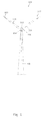
- Fig. 1 shows a wind turbine generator 100 comprising a tower 101 and a nacelle 102.
- Rotor blades 103 are fixed to a hub 104.
- the assembly of rotor blades 103, i.e. the rotor 107, is rotatable by action of the wind.
- the wind induced rotational energy of the rotor blades 103 can be transferred via the hub to a generator in the nacelle.
- the wind turbine generator 100 is capable of converting kinetic energy of the wind into mechanical energy by means of the rotor blade and, subsequently, into electric energy by means of the generator.
- Rotor blades 103 or just blades 103 include, but is not limited to, an elongated structure having an airfoil-shaped profile suitable for providing an aerodynamic lift upon relative movement through air.
- Each rotor blade is rotatable along a longitudinal axis extending in the elongated direction of a blade and perpendicular to a blade bearing 106.
- the angular position of a blade equivalently referred to as the pitch of the blade.
- a pitch actuator (not shown) is engaged with each blade to enable rotation to a given pitch position.
- the hub 104 is a structure provided with fastening means for fastening one or more rotor blades 103 and connectable with a shaft or other means for transferring the rotational energy of the blades to the generator or a gearbox.
- the blades may be provided with tip ends 108 that are rotatable by actuators.
- the blades may be provided with flaps 109 arranged along the trailing edge to modify the aerodynamic blade properties by rotation or displacement of the flaps. Motion of the flaps is possible by use of flap actuators.
- Fig. 2 shows parts of the wind turbine detection system 200 which is capable of detecting changes in the structural or dynamic behavior of blades, e.g. due to undesired loading of a wind turbine.
- the undesired loading may be caused by precipitation in the form of water, ice, salt, dirt or snow which builds up on the blade to form shells of ice over the entire blade or at portions of the blade.
- the additional blade loading caused by such blade icing may affect the dynamic and aerodynamic properties of the blade and eventually cause a failure or even breakdown of the blade.
- blade loading or other changes of the blade may cause downtime, failures of wind turbines and lost energy production.
- the changes in the structural or dynamic behavior of blades may equivalently be affected due to detachment of blade parts from the blade, cracks in the composite material of the blade or other changes which affect the behavior of the blade and, thereby, may affect the efficiency of the wind turbine or may develop into failure of a blade.
- the detection system 200 comprises one or more sensors 201 capable of detecting vibrations. Vibrations may be detected as deformations or accelerations of parts of the blade.
- the sensors may comprise deformation sensors or strain sensors such a fiber optic or electric strain gauges capable of detecting strain or stresses of the blade structure.
- the sensor may also comprise acceleration sensors such as fiber optic or piezo electric acceleration sensors capable of detecting accelerations of structural parts of the blade.
- the sensors are attached to inner and/or outer blade surfaces, e.g. surfaces of the blade shell or other blade parts such as the blade spar. Alternatively, the sensors are molded into the blade construction.
- sensor 201 may equivalently be referred to as vibration sensor, strain sensor or deformation sensors or just sensors.
- the sensors have a bandwidth enabling them to measure the structural accelerations or strains at least up to relevant resonance frequencies of the blade or blade parts.
- the resonance frequencies may be the first, second or higher resonances of flap wise, edge wise or torsion wise vibration modes.
- the detection system further comprises one or more blade actuators 220, or generally any excitation means 220, arranged for adjusting the blade or a part of the blade.
- the blade actuator is a pitch actuator whose primary use is to adjust the blade pitch and, thereby the aerodynamic properties, in order to obtain maximum power production.
- the blade actuator may comprise tip actuators and flap actuators for operation of blade tips 108 and flaps 109, respectively.
- the detection system further comprises a signal generator 213 for generating an excitation signal to the blade actuator for exciting a vibration of the blade.
- the generated signal e.g. in the form of a harmonic sinus signal or a signal containing multiple frequencies, such as a triangle signal, is supplied to the actuator either directly or indirectly via an actuator driver.
- the detection system may comprise a data acquisition unit 211 for receiving the data signal from one or more sensors 201.
- the dynamic characteristic such as the resonance frequencies and frequency response of the blade are affected due to e.g. icing or other changes of the mass or mass distribution of the blade.
- Such dynamic characteristics of the blade can be determined by exciting vibrations in the blade and, in response to the excitation, either simultaneously or delayed from the excitation, obtaining values of acceleration or deformation of the blade as a function of time.
- the acceleration or deformation may be obtained as amplitudes of acceleration or deformation at a particular frequency or at a range of frequencies, i.e. in the form of a frequency spectrum of strain amplitude values.
- the sensor signal provided by blade sensors 201 may be in the form of a time signal or a spectrum of vibration amplitudes.
- the spectrum or frequency response may be obtained by a Fourier analysis of the time signal from sensors 201.
- the detection system 200 may comprise a spectrum analyzer or FFT processor which may be integrated with the data acquisition unit 211 or the processor 212, e.g. in the form of a computer algorithm executable by the processor 212.
- the blade response in form of raw sampled data or a processed data may be obtained simultaneously with the excitation or after a short delay from the excitation and, therefore, the acquisition of data from sensors 201 is synchronized in time with the generation of the excitation signal supplied to an actuator 220. It is understood that processed data cannot be obtained simultaneously with the excitation since a time delay will be involved with the data processing.
- sensor data and possibly processed sensor data may be continuously obtained e.g. during operation or stillstand of the wind turbine, whereas excitation signals are generated at predetermined times or in dependence of parameters such as weather data.
- this detection may be used to determine changes in the dynamic, aerodynamic or structural behavior of a blade, or the detection may be used for generation of other excitation signals for confirmation of the detected change or for refinement of the detection.
- the reference signals may have been obtained from identical excitations, i.e. excitations with the same excitation signal, of the same blade or an equivalent blade which is not affected by any mass change.
- differences such as differences of the location of resonance frequencies or deformation amplitudes at particular frequencies, between the reference signal and the new sensor signal it is possible to determine an undesired loading.
- the reference signals may have been obtained from identical excitation of the same blade or an equivalent blade which is affected by a known mass, and possibly a known location of the mass. Accordingly, by attaching a mass of a given shape to a blade, it is possible to obtain a reference signal corresponding to a particular undesired loading of a particular mass and possibly a particular location. By attaching different masses to the blade in turn and obtaining the reference signal in response to a known excitation, a series of reference signals are obtained which characterize different undesired loadings.
- the reference signal may equivalently be in the form of a reference spectrum obtained by Fourier analyzing the time dependent reference signals.
- the sensor data may be used as input to a model which gives data regarding undesired loadings of the blade and possibly gives data regarding the mass and location of undesired loadings.
- the model may comprise parameters obtained from measurements or simulations of a blade which is exposed to known loadings.
- the model may be a dynamic model based on the dynamic blade properties, a neural network model or another suitable model.
- the processing unit 212 For comparison of the measured signal from a sensor 201 with a reference signal or modeling of the measured data, the processing unit 212 is provided. From the result of the comparison, e.g. determination of a shifted resonance frequency, or the modeling, the processing unit is able to determine a state of the blade, i.e. whether a mass or load disturbance is present and possibly also where on the blade the disturbance is.
- the reference signals or model parameters may be stored in an electronic storage 214, i.e. a memory.
- any of the signal generator 213, the data acquisition unit 211 and the processor 212 may be used for other purposes in the wind turbine.
- the signal generator 213 may be a signal generator used for generating reference signals for normal operation of the pitch actuator system.
- the data acquisition unit 211 may be used during normal operation of the wind turbine for monitoring static loads on the blade.
- the detection system is able to detect changes in the loading of the blades, the system is generally able to detect any change of the blade, including icing, smudging due to sand, salt, earth as well as parts of the blade which come loose.
- any blade actuator 220 or actually any excitation means 220, may be used for excitation of blade vibrations.
- an excitation is an actuator or system whose primary function is not vibration excitation, but normal operation of the wind turbine, e.g. optimization or control of energy production and control of wind turbine loadings. Accordingly, the excitation means has a secondary function for excitation of blade vibrations and, therefore, serves dual purposes.
- the pitch actuator used for adjusting the pitch of a blade may be used as an excitation means.
- Other blade actuators for excitation of vibrations comprise flap actuators and tip actuators for operation of respective blade flaps and tips.
- a blade flap is located in a recess of the trailing edge of the blade and may be rotatably hinged in the longitudinal direction of the blade. The primary use of the flap is to modify the aerodynamic profile of the blade, e.g. to modify the blade lift.
- a blade tip is an outer part of the blade which is rotatably hinged in the longitudinal direction of the blade which primary function is to modify e.g. the lift of the blade. Any of these blade actuators (pitch actuator, tip actuator, flap actuator and others) may, as a secondary function, be used for excitation of blade vibrations, e.g. by actuating the blade actuator to move back and forth.
- any of the pitch, blade tip and blade flap actuators may also excite blade vibrations by setting of the blade pitch, tip pitch and flap position so that the blade stalls due to a turbulent airflow.
- the turbulent airflow excites vibrations of the blade, which vibrations can be used equivalently to vibrations excited by repeated back and forth motion of the actuators to determine undesired blade loadings by analyzing the sensor signal.
- Vibrations may also be excited by varying the torque load on the shaft which connects the blades 103 with the generator via a gearing or other connection means.
- the generator loads the blade shaft in dependence of the electrical loading of the generator by the power converter which converts the generator voltage to a voltage suitable for the utility grid.
- the electrical loading by the power converter corresponds to the power supplied to the utility grid, or a dump load, which power is set according to a power reference supplied to the power converter. Accordingly, by varying the power reference temporarily, the torque load on the shaft varies, which will cause the blades 103 to vibrate.
- it is possible to vary the torque load on the blade shaft by temporarily and shortly activating a disc brake connected to the blade shaft so as to cause the blades to vibrate.
- such methods of varying the torque load on the blade shaft may load components of the wind turbine, e.g. the gear box, unacceptably, such methods may be successfully used in some situations.
- Vibrations excited by any of the excitation means comprising blade actuators, blade stall, electrical load and brake load variations can be measured by the sensors 201. Since the frequency response of the excited vibrations is affected by any positive or negative loading, i.e. loadings which add or subtract weight from the blade, the spectral location of resonance vibrations and generally the vibration amplitudes of the frequency response are affected by any loading. As described previously, the change of resonance frequencies and vibration amplitudes at particular frequencies of the measured spectrum is Indicative of the mass and location of any loading.
- the excitation of blade vibrations by excitation of a back and forth motion of the blade actuators may be performed when the rotor 107 is at standstill, i.e. does not rotate, when the rotor is idle, i.e. rotates slowly without generating power, or when the wind turbine is in operation, i.e. the rotor rotates and generates power.
- excitation of blade vibrations by causing blades to stall or by electrical load and brake load variations can only be performed when the wind turbine is in operation.
- the excitation signal generated by the signal generator 213 for any of the blade actuators and possibly the power reference of the power converter, may vary in time to excite blade vibrations.
- Fig. 3A shows different excitation signals that may be supplied e.g. to the pitch actuator 220.
- Excitation signal 311 represents any monotonically increasing signals comprising step, ramp and similar signals.
- Excitation signal 312 represents signals containing a superposition of a plurality of sinusoidal signals
- signal 313 represents signals such as square, triangle and other shaped signals which repeats itself as a function of time
- signal 314 represents signals which varies in frequency as a function of time such as a sinusoidal signal which frequency increases linearly as a function of time.
- a sinusoidal signal 315 having a single frequency may be used as an excitation signal.
- Any of the signals 312-315 are characterized in that a continuous part of the excitation signal has at least one part which increases as a function of time and at least one part which decreases as a function of time.
- excitation signals 311-314 includes a plurality of frequency components, either a plurality of discrete frequencies 322 or a continuous distribution of frequencies 321, 323-324, where the pluralities of frequencies are generated substantially simultaneously for signals 321-323 or time shifted for the sweep signal 324.
- Signal 325 comprises only a single frequency component 325.
- any of the excitation signals 311-315 will excite blade vibrations.
- the frequency spectrum of the excitation signals may be chosen to be close to or to include resonance frequencies of the blade.
- Fig. 4A shows the spectrum 411 of an excitation signal, which includes natural or resonance frequencies 421, 422 of the blade and is located close to resonance frequencies 423, 424.
- Fig. 4B shows a frequency response 431 obtained by Fourier processing a data signal from one or more of the sensors 201.
- the response 431 has amplitude peaks at the resonance frequencies 421-424.
- the response 431 is obtained from an unloaded blade, i.e. which is not affected by any loads such as ice.
- response 441 is obtained from a blade with undesired loading from ice.
- Frequency response 441 which is obtained from a sensor signal similarly to response 431 shows that resonance frequencies 423 and 424 are shifted due to the icing.
- Frequency response 441 also shows that vibration amplitudes in-between resonance frequencies are modified.
- the sensor signal from vibration sensors 201 or the Fourier processed sensor signal may be normalized with respect to an amplitude or a spectrum of amplitudes of the excitation signal 311-315.
- a comparison may be based on spectrums of the sensor signal obtained by a Fourier analysis
- the comparison may equally be based on the time signals from a sensor 201, since the processor 212 may have functionalities, e.g. algorithms, capable of determining the frequency content or spectrum of the time signals.
- a frequency shift of a resonance may be used to determine if positive loading is present, i.e. addition of a mass, or negative loading is present, i.e. subtraction of a mass, e.g. due to a fracture of the blade.
- a decrease of the resonance frequency means that mass, e.g.
- ice is added to the blade, and an increase of the resonance frequency means that mass, e.g. a shell of the blade, is removed from the blade.
- the value of the frequency shift of a resonance can be used to estimate the value of the mass of the undesired loading.
- the value of the undesired mass can be used to determine whether a full stop of the turbine is required, a different pitch strategy should be selected, the turbine should be de-rated, or if operation is still possible.
- increases and decreases of vibration amplitudes at frequencies other than the resonance frequencies can be used to determine any positive or negative undesired loading.
- Acquisition of the sensor signal may be performed simultaneously with transmission of the excitation signal 311-315, i.e. so that when the first value of the excitation signal is supplied, then the first values from a sensor 220 is sampled.
- the acquisition of the sensor signal may continue for as long as the excitation signal is transmitted, and possibly continue for a time after the transmission of an excitation signal has stopped.
- the acquisition or sampling of the first value from a sensor 220 may be time delayed relative to transmission of the first value of the excitation signal to an excitation means.
- the timing of acquisition of measurements from sensors 220 is synchronized with the timing of transmission of the excitation signal and, thereby, the vibration excitation.
- Processing of the acquired data signal may be performed real time so that sampled sensor data are processed when they are available.
- the processing may be performed with a delay from a number of sensor samples which have initially been stored. E.g. 100 samples may be initially be sampled and stored and then processed.
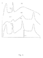
- Fig. 5 shows first, second and third Fourier transformations 511-513 of sensor signals obtained from first, second, and third vibrations sensors 201 located at different locations on the blade, e.g. distributed along the length of the blade.
- the responses 511-513 are arbitrarily shifted in the vertical direction/amplitude direction for convenience. Assume that four natural vibration modes with four different resonance frequencies are excited as shown by response 513.
- Each of the first, second and third sensors 201 detect the resonance peaks as shown by responses 511-513.
- the shape of the vibration i.e. the shape of the vibration mode, at the location of some of the sensors the amplitudes are smaller than at other locations.
- the shape of this vibration mode e.g. along the longitudinal direction of the blade, can be determined. That is, when a number of vibration amplitudes along a given direction are known and the resonance frequency is known, the mode shape can be approximated.
- the unknown spatial location of the undesired loading can be determined or estimated.
- heating means integrated in the blade can be activated at a particular location instead of heating the entire blade.
- the reference vibration modes may be determined from the previous described reference signals or reference spectra by analyzing the vibration amplitudes from different sensors 201 located at different blade locations similarly to obtaining vibration mode shapes from non-reference measurements.
- Fig. 6 shows vibration modes of the blade comprising edge wise modes 611, torsion modes 612 around the longitudinal axis of the blade and flap wise modes 613 in a direction out of the paper.
- the vibration sensor 201, 601-603 may be placed on the blade so as to enable to best possible detection of particular vibration modes.
- the sensor signals or sensor spectra may be parameterized with respect to wind speed, temperature, humidity and other parameters.
- the reference signal, the reference spectra and reference modes may be parameterized with respect to such parameters so that a comparison between sensor signals and references are made independent on any such parameters.
- the excitation signal supplied e.g. to a pitch actuator is adaptively adjusted depending on the measured sensor signals.
- the bandwidth, i.e. the spectrum, of the excitation signal may be narrowed if the response shows that that a particular frequency has shifted - in that case the spectrum may be narrowed so that it only excites this relevant frequency.
- the amplitude of the excitation signal may be reduced to reduce vibration amplitudes, or the excitation amplitude may be increased if the sensor response is too weak.
- the frequency or spectrum of the excitation signal may be increased throughout a particular range to excite different vibration modes so as to search for possible undesired loadings and possibly search for particular locations on the blade of undesired loadings.
- the adjustment of the excitation signal based on the response may be performed by the processor 212 which sends instructions to the signal generator 213 as by the dotted line in Fig. 2 .
Description
- The invention relates to wind turbine systems and in particular to systems for detection of blade icing.
- Downtime and failures of wind turbines due to undesired loading of wind turbine blades, primarily due to icing is unacceptable in modern wind turbines. Similarly, even small ice accretion impacts the power curve of a wind turbine and, therefore, implies lost production. Furthermore, ice may shed from a blade and cause personal injuries or damages to technical installations.
- Accordingly, methods for detection of icing and other undesired blade loading are desired to avoid such problems.
-
US2005276696 discloses a method for detecting ice on a wind turbine having a rotor and one or more rotor blades each having blade roots, including monitoring meteorological conditions relating to icing conditions and monitoring one or more physical characteristics of the wind turbine in operation that vary in accordance with at least one of the mass of the one or more rotor blades or a mass imbalance between the rotor blades. The method also includes using the one or more monitored physical characteristics to determine whether a blade mass anomaly exists, determining whether the monitored meteorological conditions are consistent with blade icing; and signaling an icing-related blade mass anomaly when a blade mass anomaly is determined to exist and the monitored meteorological conditions are determined to be consistent with icing. - Whereas
US2005276696 discloses a method for detecting blade icing, the inventors of the present invention have appreciated that an improvement of blade icing detection is of benefit, and have in consequence devised the present invention. -
EP2112375 describes a method of detecting the formation of ice on the blades of a wind turbine. -
EP2075462 describes a wind turbine, wind turbine controller and method for controlling a wind turbine. -
US 2010/158688 describes an aerodynamic device for the detection of physical conditions of wind turbine blade operation. -
WO 2006/012827 describes a method and a device for monitoring the state of rotor blades on wind power installations. - It would be advantageous to achieve improved methods and systems for detection of undesired loading of blades on wind turbines, e.g. due to icing. Generally it would be desirable to improve blade load detection for achieving faster detection, more reliable detection, cheaper detection systems or more flexible detection systems which may enable load detection of blades both when the wind turbine is in operating and non-operating states. In general, the invention preferably seeks to meet any of the above mentioned objectives singly or in any combination or to provide a method that solves such other problems of the prior art.
- To better address one or more of these concerns, in a first aspect of the invention a wind turbine system for detecting a change in the structural, dynamic or aerodynamic behavior of a wind turbine blade is presented, where the system comprises
- one or more sensors capable of detecting vibrations of the wind turbine blade,
- an exciter capable of exciting a vibration of the blades, where the exciter has primary and secondary functions, the primary function is for operation of the wind turbine and the secondary function is for vibration excitation,
- a signal generator for generating an excitation signal to the exciter for exciting a vibration of the blade,
- a data acquisition unit for receiving a data signal from the one or more sensors,
- a processing unit for determining changes in the structural behavior of the blade on basis of the sensor signal.
- Since the detection of undesired loading is obtained from active vibration excitation, the system may advantageously enable detection of undesired loadings both when the rotor is at standstill, when the rotor is freely rotating and when in rotor is in operation. Furthermore, due to the use of active vibration excitation, the vibration response can be obtained simultaneously or almost simultaneously with the excitation so that the detection of possible icing can be determined very rapidly.
- The processing of the sensor signal may comprise comparing the sensor signal with a reference or using the sensor data as input to a mathematical model for determining behavioral changes of the blade.
- The excitation signal may be superposed to the operating signal used for the exciter's primary function in operation of the wind turbine, or the excitation signal may be used for excitation of the exciter when the exciter is not operated according to its primary function.
- Generally the invention may improve the precision of the ice detection which may enable automatic restart of the wind turbine generator. Increased precision on ice detection may also improve the operation and power production of wind turbines equipped with active de-icing functionality. In this case it will be possible to activate e.g. a heating system at a lower level of ice accretion on the blades and thereby optimize the production by reducing the aerodynamic impact of ice on blades.
- An embodiment of the system further comprises a spectrum analyzer for determining the frequency spectrum of the acquired sensor signal. The frequency spectrum may be used as input to a mathematical model or for comparing with a reference spectrum. Since the spectrum may be affected by the state of the blade, i.e. affected by loadings or other structural, dynamic or aerodynamic changes of the blade, the spectrum may advantageously be used for assessing the actual behavior or state of the blade.
- In an embodiment a continuous part of the excitation signal may comprise at least one increasing part and at least one decreasing part. In other words, the excitation signal may be a signal which both increases and decreases as a function of time for generating a reciprocal motion or action of the exciter, e.g. a pitch actuator. Alternatively, the excitation signal may comprise only an increasing or decreasing part, such as a step signal or ramp signal, for exciting a kind of a step response.
- In an embodiment the excitation signal may comprise a plurality of frequency components. That is, the excitation signal may be in the form of sweep, i.e. a signal having a frequency which varies as a function of time, or the excitation signal may comprise a plurality of frequency components which are superposed. Thus, in an embodiment the excitation signal may vary in frequency as a function of time.
- In an embodiment the processing unit may be capable of determining a new excitation signal for the signal generator, where the frequency content of the excitation signal is changed in dependence of the previously acquired data signal. In this way the excitation signal may be fine tuned adaptively, e.g. for improving the accuracy of detection of changes in a blade's behavior or for localization of a load, a crack or other damage in the blade.
- In an embodiment the excitation means may be a blade actuator, such as a pitch actuator arranged for adjusting the pitch of the blade.
- In an embodiment the data signal from the one or more sensors are acquired together with other measured parameter types comprising one or more of wind speed, temperature, humidity, blade pitch, azimuth of the nacelle and yaw of the nacelle. The other parameters may be used as input for the mathematical model, or the acquired sensor signal may be compared with reference signals which are parameterized with respect to such parameter types.
- In an embodiment the acquisition is synchronized in time with the generation of the excitation signal. The synchronization of exciting the blade and sampling data from the blade sensor may be performed so that sensor data are obtained simultaneously with the excitation from the start of the excitation, the sensor data may be obtained after a delay from the start of excitation in order to measure only steady-state vibrations, or the sensor data may be obtained after the excitation has stopped in order to measure only the decay response of the excitation.
- A second aspect of the invention relates to a wind turbine comprising the detection system according to the first aspect for detecting an undesired loading of a wind turbine.
- A third aspect of the invention relates to a method for detecting a change in the structural behavior of a wind turbine blade, the method comprises
- exciting a vibration of the blade using an exciter which has primary and secondary functions, the primary function is for normal operation of the wind turbine and the secondary function is for vibration excitation,
- acquiring a data signal from one or more blade sensors capable of detecting blade vibrations or blade deformations,
- processing the data signal for determining changes in the structural behavior of the blade on basis of the sensor signal.
- In summary the invention relates to a method for detecting icing, other loadings on blades or changes of the blade which affect the structural, dynamic or aerodynamic behavior of wind turbines. Advantageously, the method utilizes existing wind turbine actuators, for example pitch actuators, for excitation of blade vibrations. Vibration sensors on the blade such as strain sensors or accelerometers measure the blade vibrations excited in response to the actively excited vibrations. By comparing the measured response with previously obtained reference responses, it is possible to determine if blade icing is present.
- In general the various aspects of the invention may be combined and coupled in any way possible within the scope of the invention. These and other aspects, features and/or advantages of the invention will be apparent from and elucidated with reference to the embodiments described hereinafter.
- Embodiments of the invention will be described, by way of example only, with reference to the drawings, in which
-
Fig. 1 shows a wind turbine generator, -
Fig. 2 shows a system for detection of undesired blade loading, -
Fig. 3A-B show examples of excitations signals, -
Fig. 4A shows the frequency spectrum of an excitation signal in comparison with resonance frequencies of a blade, -
Fig. 4B shows a spectrum of a sensor signal obtained in response to a vibration excitation in comparison with a reference spectrum, -
Fig. 5 shows vibration spectra obtained from sensors located at different blade positions, -
Fig. 6 shows a blade with a plurality of vibration sensors. -
Fig. 1 shows awind turbine generator 100 comprising atower 101 and a nacelle 102.Rotor blades 103 are fixed to ahub 104. The assembly ofrotor blades 103, i.e. therotor 107, is rotatable by action of the wind. The wind induced rotational energy of therotor blades 103 can be transferred via the hub to a generator in the nacelle. Thus, thewind turbine generator 100 is capable of converting kinetic energy of the wind into mechanical energy by means of the rotor blade and, subsequently, into electric energy by means of the generator. -
Rotor blades 103 or justblades 103 include, but is not limited to, an elongated structure having an airfoil-shaped profile suitable for providing an aerodynamic lift upon relative movement through air. Each rotor blade is rotatable along a longitudinal axis extending in the elongated direction of a blade and perpendicular to ablade bearing 106. The angular position of a blade equivalently referred to as the pitch of the blade. A pitch actuator (not shown) is engaged with each blade to enable rotation to a given pitch position. - The
hub 104 is a structure provided with fastening means for fastening one ormore rotor blades 103 and connectable with a shaft or other means for transferring the rotational energy of the blades to the generator or a gearbox. - Alternatively or additionally, the blades may be provided with tip ends 108 that are rotatable by actuators. Furthermore, the blades may be provided with
flaps 109 arranged along the trailing edge to modify the aerodynamic blade properties by rotation or displacement of the flaps. Motion of the flaps is possible by use of flap actuators. -
Fig. 2 shows parts of the windturbine detection system 200 which is capable of detecting changes in the structural or dynamic behavior of blades, e.g. due to undesired loading of a wind turbine. The undesired loading may be caused by precipitation in the form of water, ice, salt, dirt or snow which builds up on the blade to form shells of ice over the entire blade or at portions of the blade. The additional blade loading caused by such blade icing may affect the dynamic and aerodynamic properties of the blade and eventually cause a failure or even breakdown of the blade. Furthermore, blade loading or other changes of the blade may cause downtime, failures of wind turbines and lost energy production. - The changes in the structural or dynamic behavior of blades may equivalently be affected due to detachment of blade parts from the blade, cracks in the composite material of the blade or other changes which affect the behavior of the blade and, thereby, may affect the efficiency of the wind turbine or may develop into failure of a blade.
- The
detection system 200 comprises one ormore sensors 201 capable of detecting vibrations. Vibrations may be detected as deformations or accelerations of parts of the blade. The sensors may comprise deformation sensors or strain sensors such a fiber optic or electric strain gauges capable of detecting strain or stresses of the blade structure. The sensor may also comprise acceleration sensors such as fiber optic or piezo electric acceleration sensors capable of detecting accelerations of structural parts of the blade. The sensors are attached to inner and/or outer blade surfaces, e.g. surfaces of the blade shell or other blade parts such as the blade spar. Alternatively, the sensors are molded into the blade construction. Throughout the description,sensor 201 may equivalently be referred to as vibration sensor, strain sensor or deformation sensors or just sensors. - Preferably, the sensors have a bandwidth enabling them to measure the structural accelerations or strains at least up to relevant resonance frequencies of the blade or blade parts. The resonance frequencies may be the first, second or higher resonances of flap wise, edge wise or torsion wise vibration modes.
- The detection system further comprises one or more blade actuators 220, or generally any excitation means 220, arranged for adjusting the blade or a part of the blade. In an embodiment the blade actuator is a pitch actuator whose primary use is to adjust the blade pitch and, thereby the aerodynamic properties, in order to obtain maximum power production. Alternatively or additionally, the blade actuator may comprise tip actuators and flap actuators for operation of blade tips 108 and flaps 109, respectively.
- The detection system further comprises a
signal generator 213 for generating an excitation signal to the blade actuator for exciting a vibration of the blade. The generated signal, e.g. in the form of a harmonic sinus signal or a signal containing multiple frequencies, such as a triangle signal, is supplied to the actuator either directly or indirectly via an actuator driver. - The detection system may comprise a data acquisition unit 211 for receiving the data signal from one or
more sensors 201. - The dynamic characteristic, such as the resonance frequencies and frequency response of the blade are affected due to e.g. icing or other changes of the mass or mass distribution of the blade. Such dynamic characteristics of the blade can be determined by exciting vibrations in the blade and, in response to the excitation, either simultaneously or delayed from the excitation, obtaining values of acceleration or deformation of the blade as a function of time. The acceleration or deformation may be obtained as amplitudes of acceleration or deformation at a particular frequency or at a range of frequencies, i.e. in the form of a frequency spectrum of strain amplitude values.
- Accordingly, by exciting a vibration in the
blade 103 by use of ablade actuator 213 and measuring the response via one or more of theblade sensors 201 it is possible to obtain information of the dynamic properties of the blade, e.g. information about changes of resonance frequencies or changes in the spectrum of strain values or vibration amplitudes. - The sensor signal provided by
blade sensors 201 may be in the form of a time signal or a spectrum of vibration amplitudes. The spectrum or frequency response may be obtained by a Fourier analysis of the time signal fromsensors 201. For that purpose thedetection system 200 may comprise a spectrum analyzer or FFT processor which may be integrated with the data acquisition unit 211 or theprocessor 212, e.g. in the form of a computer algorithm executable by theprocessor 212. - The blade response in form of raw sampled data or a processed data may be obtained simultaneously with the excitation or after a short delay from the excitation and, therefore, the acquisition of data from
sensors 201 is synchronized in time with the generation of the excitation signal supplied to an actuator 220. It is understood that processed data cannot be obtained simultaneously with the excitation since a time delay will be involved with the data processing. - Alternatively, sensor data and possibly processed sensor data, e.g. FFT data, may be continuously obtained e.g. during operation or stillstand of the wind turbine, whereas excitation signals are generated at predetermined times or in dependence of parameters such as weather data. Thus, if a change of a resonance frequency or another change of the data signal is detected during the continuous sampling of sensor data, this detection may be used to determine changes in the dynamic, aerodynamic or structural behavior of a blade, or the detection may be used for generation of other excitation signals for confirmation of the detected change or for refinement of the detection.
- By comparing the acquired sensor signal with reference signals, e.g. by use of a processor or
computer 212, it is possible to infer if any undesired loading of the blade is present. - The reference signals may have been obtained from identical excitations, i.e. excitations with the same excitation signal, of the same blade or an equivalent blade which is not affected by any mass change. Thus, by determining differences, such as differences of the location of resonance frequencies or deformation amplitudes at particular frequencies, between the reference signal and the new sensor signal it is possible to determine an undesired loading.
- Alternatively, the reference signals may have been obtained from identical excitation of the same blade or an equivalent blade which is affected by a known mass, and possibly a known location of the mass. Accordingly, by attaching a mass of a given shape to a blade, it is possible to obtain a reference signal corresponding to a particular undesired loading of a particular mass and possibly a particular location. By attaching different masses to the blade in turn and obtaining the reference signal in response to a known excitation, a series of reference signals are obtained which characterize different undesired loadings.
- The reference signal may equivalently be in the form of a reference spectrum obtained by Fourier analyzing the time dependent reference signals.
- Instead of comparing the sensor data with reference data, the sensor data may be used as input to a model which gives data regarding undesired loadings of the blade and possibly gives data regarding the mass and location of undesired loadings. The model may comprise parameters obtained from measurements or simulations of a blade which is exposed to known loadings. The model may be a dynamic model based on the dynamic blade properties, a neural network model or another suitable model.
- For comparison of the measured signal from a
sensor 201 with a reference signal or modeling of the measured data, theprocessing unit 212 is provided. From the result of the comparison, e.g. determination of a shifted resonance frequency, or the modeling, the processing unit is able to determine a state of the blade, i.e. whether a mass or load disturbance is present and possibly also where on the blade the disturbance is. The reference signals or model parameters may be stored in an electronic storage 214, i.e. a memory. - Any of the
signal generator 213, the data acquisition unit 211 and theprocessor 212 may be used for other purposes in the wind turbine. For example, thesignal generator 213 may be a signal generator used for generating reference signals for normal operation of the pitch actuator system. The data acquisition unit 211 may be used during normal operation of the wind turbine for monitoring static loads on the blade. - Since the detection system is able to detect changes in the loading of the blades, the system is generally able to detect any change of the blade, including icing, smudging due to sand, salt, earth as well as parts of the blade which come loose.
- In general any blade actuator 220, or actually any excitation means 220, may be used for excitation of blade vibrations. Here an excitation is an actuator or system whose primary function is not vibration excitation, but normal operation of the wind turbine, e.g. optimization or control of energy production and control of wind turbine loadings. Accordingly, the excitation means has a secondary function for excitation of blade vibrations and, therefore, serves dual purposes.
- The pitch actuator used for adjusting the pitch of a blade may be used as an excitation means. Other blade actuators for excitation of vibrations comprise flap actuators and tip actuators for operation of respective blade flaps and tips. A blade flap is located in a recess of the trailing edge of the blade and may be rotatably hinged in the longitudinal direction of the blade. The primary use of the flap is to modify the aerodynamic profile of the blade, e.g. to modify the blade lift. A blade tip is an outer part of the blade which is rotatably hinged in the longitudinal direction of the blade which primary function is to modify e.g. the lift of the blade. Any of these blade actuators (pitch actuator, tip actuator, flap actuator and others) may, as a secondary function, be used for excitation of blade vibrations, e.g. by actuating the blade actuator to move back and forth.
- Any of the pitch, blade tip and blade flap actuators may also excite blade vibrations by setting of the blade pitch, tip pitch and flap position so that the blade stalls due to a turbulent airflow. The turbulent airflow excites vibrations of the blade, which vibrations can be used equivalently to vibrations excited by repeated back and forth motion of the actuators to determine undesired blade loadings by analyzing the sensor signal.
- Vibrations may also be excited by varying the torque load on the shaft which connects the
blades 103 with the generator via a gearing or other connection means. The generator loads the blade shaft in dependence of the electrical loading of the generator by the power converter which converts the generator voltage to a voltage suitable for the utility grid. The electrical loading by the power converter corresponds to the power supplied to the utility grid, or a dump load, which power is set according to a power reference supplied to the power converter. Accordingly, by varying the power reference temporarily, the torque load on the shaft varies, which will cause theblades 103 to vibrate. Similarly, it is possible to vary the torque load on the blade shaft by temporarily and shortly activating a disc brake connected to the blade shaft so as to cause the blades to vibrate. Whereas such methods of varying the torque load on the blade shaft may load components of the wind turbine, e.g. the gear box, unacceptably, such methods may be successfully used in some situations. - Vibrations excited by any of the excitation means comprising blade actuators, blade stall, electrical load and brake load variations can be measured by the
sensors 201. Since the frequency response of the excited vibrations is affected by any positive or negative loading, i.e. loadings which add or subtract weight from the blade, the spectral location of resonance vibrations and generally the vibration amplitudes of the frequency response are affected by any loading. As described previously, the change of resonance frequencies and vibration amplitudes at particular frequencies of the measured spectrum is Indicative of the mass and location of any loading. - The excitation of blade vibrations by excitation of a back and forth motion of the blade actuators may be performed when the
rotor 107 is at standstill, i.e. does not rotate, when the rotor is idle, i.e. rotates slowly without generating power, or when the wind turbine is in operation, i.e. the rotor rotates and generates power. In comparison, excitation of blade vibrations by causing blades to stall or by electrical load and brake load variations can only be performed when the wind turbine is in operation. - The excitation signal generated by the
signal generator 213 for any of the blade actuators and possibly the power reference of the power converter, may vary in time to excite blade vibrations. -
Fig. 3A shows different excitation signals that may be supplied e.g. to the pitch actuator 220. Excitation signal 311 represents any monotonically increasing signals comprising step, ramp and similar signals. Excitation signal 312 represents signals containing a superposition of a plurality of sinusoidal signals, signal 313 represents signals such as square, triangle and other shaped signals which repeats itself as a function of time, and signal 314 represents signals which varies in frequency as a function of time such as a sinusoidal signal which frequency increases linearly as a function of time. Alternatively asinusoidal signal 315 having a single frequency may be used as an excitation signal. Any of the signals 312-315 are characterized in that a continuous part of the excitation signal has at least one part which increases as a function of time and at least one part which decreases as a function of time. -
Fig. 3B shows the frequency spectra 321-325 of the signals 311-315. Accordingly, excitation signals 311-314 includes a plurality of frequency components, either a plurality of discrete frequencies 322 or a continuous distribution offrequencies 321, 323-324, where the pluralities of frequencies are generated substantially simultaneously for signals 321-323 or time shifted for thesweep signal 324. Signal 325 comprises only a single frequency component 325. - Any of the excitation signals 311-315 will excite blade vibrations. The frequency spectrum of the excitation signals may be chosen to be close to or to include resonance frequencies of the blade.
-
Fig. 4A shows the spectrum 411 of an excitation signal, which includes natural orresonance frequencies 421, 422 of the blade and is located close toresonance frequencies 423, 424. -
Fig. 4B shows a frequency response 431 obtained by Fourier processing a data signal from one or more of thesensors 201. The response 431 has amplitude peaks at the resonance frequencies 421-424. The response 431 is obtained from an unloaded blade, i.e. which is not affected by any loads such as ice. In comparison, response 441 is obtained from a blade with undesired loading from ice. Frequency response 441 which is obtained from a sensor signal similarly to response 431 shows thatresonance frequencies 423 and 424 are shifted due to the icing. Frequency response 441 also shows that vibration amplitudes in-between resonance frequencies are modified. - Since the vibration amplitudes including resonance amplitudes may depend on the amplitude of the excitation signal 311-315, the sensor signal from
vibration sensors 201 or the Fourier processed sensor signal may be normalized with respect to an amplitude or a spectrum of amplitudes of the excitation signal 311-315. - By comparing the acquired sensor signal which may be in the form of a Fast Fourier Transform 441 of the sensor signal with a reference signal, frequency shifts Δf1, Δf2 of resonances 421-424 and changes in the vibration amplitudes ΔA(f3) can be determined, and from this it is possible to determine if any undesired loading is present.
- Whereas a comparison may be based on spectrums of the sensor signal obtained by a Fourier analysis, the comparison may equally be based on the time signals from a
sensor 201, since theprocessor 212 may have functionalities, e.g. algorithms, capable of determining the frequency content or spectrum of the time signals. - For example, if one of the resonances 421-424 has shifted by a given frequency, e.g. 1 Hz, or if the vibration amplitude has changed by a certain amount, e.g. 20 percent of the amplitude of the unloaded blade, this triggers the
processor 212 to generate a warning signal indicating that some loading is present. The direction of a frequency shift of a resonance may be used to determine if positive loading is present, i.e. addition of a mass, or negative loading is present, i.e. subtraction of a mass, e.g. due to a fracture of the blade. Normally, a decrease of the resonance frequency means that mass, e.g. ice is added to the blade, and an increase of the resonance frequency means that mass, e.g. a shell of the blade, is removed from the blade. Similarly, the value of the frequency shift of a resonance can be used to estimate the value of the mass of the undesired loading. The value of the undesired mass can be used to determine whether a full stop of the turbine is required, a different pitch strategy should be selected, the turbine should be de-rated, or if operation is still possible. In the same way, increases and decreases of vibration amplitudes at frequencies other than the resonance frequencies can be used to determine any positive or negative undesired loading. - Acquisition of the sensor signal may be performed simultaneously with transmission of the excitation signal 311-315, i.e. so that when the first value of the excitation signal is supplied, then the first values from a sensor 220 is sampled. The acquisition of the sensor signal may continue for as long as the excitation signal is transmitted, and possibly continue for a time after the transmission of an excitation signal has stopped. Alternatively, the acquisition or sampling of the first value from a sensor 220 may be time delayed relative to transmission of the first value of the excitation signal to an excitation means. Thus, in general the timing of acquisition of measurements from sensors 220 is synchronized with the timing of transmission of the excitation signal and, thereby, the vibration excitation. Processing of the acquired data signal, such as Fourier processing may be performed real time so that sampled sensor data are processed when they are available. Alternatively, the processing may be performed with a delay from a number of sensor samples which have initially been stored. E.g. 100 samples may be initially be sampled and stored and then processed.
-
Fig. 5 shows first, second and third Fourier transformations 511-513 of sensor signals obtained from first, second, andthird vibrations sensors 201 located at different locations on the blade, e.g. distributed along the length of the blade. The responses 511-513 are arbitrarily shifted in the vertical direction/amplitude direction for convenience. Assume that four natural vibration modes with four different resonance frequencies are excited as shown by response 513. Each of the first, second andthird sensors 201 detect the resonance peaks as shown by responses 511-513. However, due to the shape of the vibration, i.e. the shape of the vibration mode, at the location of some of the sensors the amplitudes are smaller than at other locations. Assume that it has been detected that the frequency of resonance peaks 521-523 are shifted relative to thereference resonance frequency 423, then by analyzing amplitudes of the peaks 521-523 the shape of this vibration mode, e.g. along the longitudinal direction of the blade, can be determined. That is, when a number of vibration amplitudes along a given direction are known and the resonance frequency is known, the mode shape can be approximated. By comparing the determined shape of the vibration with a reference vibration mode obtained with a know location of an undesired loading, the unknown spatial location of the undesired loading can be determined or estimated. - It may be advantageous to be able to determine the location of ice on a blade, since heating means integrated in the blade can be activated at a particular location instead of heating the entire blade.
- The capability of locating the ice accretion on the blade will also enable a better risk evaluation of ice shredding. This can again lead to a better operational strategy for the wind turbine generator which optimizes the operational period.
- The reference vibration modes may be determined from the previous described reference signals or reference spectra by analyzing the vibration amplitudes from
different sensors 201 located at different blade locations similarly to obtaining vibration mode shapes from non-reference measurements. -
Fig. 6 shows vibration modes of the blade comprising edgewise modes 611,torsion modes 612 around the longitudinal axis of the blade and flap wise modes 613 in a direction out of the paper. Thevibration sensor 201, 601-603 may be placed on the blade so as to enable to best possible detection of particular vibration modes. - Since wind speed, temperature and humidity may affect the measurements from the
sensors 201, the sensor signals or sensor spectra may be parameterized with respect to wind speed, temperature, humidity and other parameters. Similarly, the reference signal, the reference spectra and reference modes may be parameterized with respect to such parameters so that a comparison between sensor signals and references are made independent on any such parameters. - In an embodiment the excitation signal supplied e.g. to a pitch actuator is adaptively adjusted depending on the measured sensor signals. For example, the bandwidth, i.e. the spectrum, of the excitation signal may be narrowed if the response shows that that a particular frequency has shifted - in that case the spectrum may be narrowed so that it only excites this relevant frequency. Similarly, the amplitude of the excitation signal may be reduced to reduce vibration amplitudes, or the excitation amplitude may be increased if the sensor response is too weak. As another example the frequency or spectrum of the excitation signal may be increased throughout a particular range to excite different vibration modes so as to search for possible undesired loadings and possibly search for particular locations on the blade of undesired loadings. The adjustment of the excitation signal based on the response may be performed by the
processor 212 which sends instructions to thesignal generator 213 as by the dotted line inFig. 2 . - While the invention has been illustrated and described in detail in the drawings and foregoing description, such illustration and description are to be considered illustrative or exemplary and not restrictive; the invention is not limited to the disclosed embodiments. Other variations to the disclosed embodiments can be understood and effected by those skilled in the art in practicing the claimed invention, from a study of the drawings, the disclosure, and the appended claims. In the claims, the word "comprising" does not exclude other elements or steps, and the indefinite article "a" or "an" does not exclude a plurality. A single processor or other unit may fulfill the functions of several items recited in the claims. The mere fact that certain measures are recited in mutually different dependent claims does not indicate that a combination of these measures cannot be used to advantage. Any reference signs in the claims should not be construed as limiting the scope.
Claims (10)
- A wind turbine system (200) for detecting a change in the structural, dynamic or aerodynamic behavior of a wind turbine blade (103), the system comprises- one or more sensors (201) capable of detecting vibrations or deformations of the wind turbine blade,- an exciter (220) capable of exciting a vibration of the blades, where the exciter has primary and secondary functions, the primary function is for operation of the wind turbine and the secondary function is for vibration excitation,- a signal generator (213) for generating an excitation signal to the exciter for exciting a vibration of the blade,- a data acquisition unit (211) for receiving a data signal from the one or more sensors,- a processing unit (212) for determining changes in the structural behavior of the blade on basis of the sensor signal.
- A system according to any of the preceding claims, further comprising a spectrum analyzer for determining the frequency spectrum of the acquired sensor signal.
- A system according to any of the preceding claims, where a continuous part of the excitation signal comprises at least one increasing part and at least one decreasing part.
- A system according to any of the preceding claims, where the excitation signal comprises a plurality of frequency components.
- A system according to any of the preceding claims, where the processing unit is capable of determining a new excitation signal for the signal generator, where the frequency content of the excitation signal is changed in dependence of the previously acquired data signal.
- A system according to any of the preceding claims, where the excitation means is a blade actuator, such as a pitch actuator arranged for adjusting the pitch of the blade.
- A system according to any of the preceding claims, where the data signal from the one or more sensors are acquired together with other measured parameter types comprising one or more of wind speed, temperature, humidity, pitch, azimuth and yaw.
- A system according to any of the preceding claims, where the acquisition the sensor signal is synchronized in time with the generation of the excitation signal
- A wind turbine (100) comprising the detection system according to claim 1 for detecting an undesired loading of a wind turbine.
- A method for detecting a change in the structural behavior of a wind turbine blade (103), the method comprises- exciting a vibration of the blade using an exciter (220) which has primary and secondary functions, the primary function is for normal operation of the wind turbine and the secondary function is for vibration excitation,- acquiring a data signal from one or more blade sensors capable of detecting blade vibrations or blade deformations,- processing the data signal for determining changes in the structural behavior of the blade on basis of the sensor signal.
Applications Claiming Priority (3)
| Application Number | Priority Date | Filing Date | Title |
|---|---|---|---|
| US36011210P | 2010-06-30 | 2010-06-30 | |
| DKPA201070306 | 2010-06-30 | ||
| PCT/DK2011/050244 WO2012000509A2 (en) | 2010-06-30 | 2011-06-29 | Wind turbine system for detection of blade icing |
Publications (2)
| Publication Number | Publication Date |
|---|---|
| EP2588752A2 EP2588752A2 (en) | 2013-05-08 |
| EP2588752B1 true EP2588752B1 (en) | 2015-07-22 |
Family
ID=44627837
Family Applications (1)
| Application Number | Title | Priority Date | Filing Date |
|---|---|---|---|
| EP11729051.0A Active EP2588752B1 (en) | 2010-06-30 | 2011-06-29 | Wind turbine system for detection of blade icing |
Country Status (5)
| Country | Link |
|---|---|
| US (1) | US9567869B2 (en) |
| EP (1) | EP2588752B1 (en) |
| CA (1) | CA2803481C (en) |
| DK (1) | DK2588752T3 (en) |
| WO (1) | WO2012000509A2 (en) |
Cited By (3)
| Publication number | Priority date | Publication date | Assignee | Title |
|---|---|---|---|---|
| DE102014117914B4 (en) | 2014-12-04 | 2021-11-11 | fos4X GmbH | Method for detecting a flutter of a rotor blade of a wind turbine |
| EP3397860B1 (en) * | 2015-12-29 | 2022-02-23 | FOS4X GmbH | Method for ascertaining a value of an ice buildup quantity on at least one rotor blade of a wind turbine, and use thereof |
| EP4172498B1 (en) * | 2020-08-14 | 2024-02-07 | Siemens Gamesa Renewable Energy A/S | Monitoring of blades in wind turbines |
Families Citing this family (34)
| Publication number | Priority date | Publication date | Assignee | Title |
|---|---|---|---|---|
| WO2012125842A2 (en) * | 2011-03-15 | 2012-09-20 | Purdue Research Foundation | Load shape control of wind turbines |
| US9964098B2 (en) * | 2011-12-20 | 2018-05-08 | Vestas Wind Systems A/S | Method of controlling a wind turbine, and a wind turbine |
| EP2565447A1 (en) * | 2012-02-14 | 2013-03-06 | Siemens Aktiengesellschaft | Method for constructing, optimising or monitoring the status of a wind power assembly or a component or a construction element of a wind power assembly |
| DE102013202261A1 (en) | 2013-02-12 | 2014-08-28 | Senvion Se | Method for checking the operation of a wind turbine and wind turbine |
| US9638168B2 (en) * | 2013-04-11 | 2017-05-02 | General Electric Company | System and method for detecting ice on a wind turbine rotor blade |
| CN105408625B (en) * | 2013-07-30 | 2018-10-19 | 维斯塔斯风力系统集团公司 | The operating method and device of wind turbine based on the load and acceleration that are measured on blade |
| DE102013221401A1 (en) * | 2013-10-22 | 2015-04-23 | Robert Bosch Gmbh | Method for detecting a state change of a plant |
| WO2016012372A1 (en) * | 2014-07-21 | 2016-01-28 | Brüel & Kjær Sound & Vibration Measurement A/S | System and methodology for detecting structural damages of wind turbine rotor blades |
| EP3009673A1 (en) * | 2014-10-15 | 2016-04-20 | Siemens Aktiengesellschaft | Operating a wind turbine during standstill, involving particularly the detection of rotor blades icing |
| DE102014117915A1 (en) * | 2014-12-04 | 2016-06-09 | fos4X GmbH | Method for monitoring a wind turbine, method for detecting ice on a wind turbine, acceleration sensor for a rotor blade, rotor blade with acceleration sensor, and profile for a rotor blade |
| US10767633B2 (en) | 2014-12-23 | 2020-09-08 | Vestas Wind Systems A/S | Method and system for determining the dynamic twist of a wind turbine blade |
| ES2895709T3 (en) | 2015-11-06 | 2022-02-22 | Nordex Energy Spain S A | Wind Turbine and Wind Turbine Ice Removal Method |
| DE102015121981A1 (en) * | 2015-12-16 | 2017-06-22 | fos4X GmbH | Method and device for operating a wind turbine |
| DE102015122932A1 (en) * | 2015-12-29 | 2017-06-29 | fos4X GmbH | A method for predicting the deposition of ice on a rotor blade of a wind turbine and its use |
| CN105863972B (en) * | 2016-06-02 | 2019-08-02 | 湖南科技大学 | A kind of automatic anti-icing and deicing system of fan blade and anti-icing and deicing method |
| CN106468246A (en) * | 2016-11-23 | 2017-03-01 | 四川大学 | The radial direction heating ice-melt blade of wind-driven generator and ice-melting device and its de-icing method |
| CN106351790A (en) * | 2016-11-23 | 2017-01-25 | 四川大学 | Transversely heated ice melting blade of wind turbine and the device and method of melting |
| DK3559456T3 (en) * | 2016-12-22 | 2022-07-18 | Vestas Wind Sys As | ENHANCED WIND TURBINE SAFETY SYSTEM |
| US10982657B2 (en) * | 2016-12-22 | 2021-04-20 | Vestas Wind Systems A/S | Temperature control based on weather forecasting |
| DE102017115927A1 (en) * | 2017-07-14 | 2019-01-17 | fos4X GmbH | Strain and vibration measuring system for monitoring rotor blades |
| WO2019120408A1 (en) * | 2017-12-22 | 2019-06-27 | Vestas Wind Systems A/S | Determining icing condition using mechanical wind sensor |
| EP3667065A1 (en) * | 2018-12-13 | 2020-06-17 | Siemens Gamesa Renewable Energy A/S | Removing vibrations in wind turbine blades |
| EP3623616A1 (en) * | 2019-08-23 | 2020-03-18 | Ventus Engineering GmbH | Detection of abnormal conditions on a wind turbine generator |
| US20230011028A1 (en) * | 2019-12-17 | 2023-01-12 | General Electric Company | System and method for monitoring rotor blade health of a wind turbine |
| DE102019135108A1 (en) * | 2019-12-19 | 2021-06-24 | Weidmüller Monitoring Systems Gmbh | Method and device for determining a change in a mass distribution of a rotor blade of a wind turbine |
| DE102020105053A1 (en) * | 2020-02-26 | 2021-08-26 | fos4X GmbH | Method for monitoring the condition of a drive train or tower of a wind energy installation and wind energy installation |
| WO2021223823A1 (en) * | 2020-05-04 | 2021-11-11 | Vestas Wind Systems A/S | Blade monitoring by actively promoting blade vibrations |
| CN112727714B (en) * | 2021-01-11 | 2022-07-12 | 宁夏汇力能源科技有限公司 | Blade deicing device and method for wind power generation |
| EP4039971A1 (en) * | 2021-02-09 | 2022-08-10 | Siemens Gamesa Renewable Energy A/S | Wind turbine rotor blade |
| CN113176083B (en) * | 2021-04-19 | 2023-07-04 | 西安交通大学 | Vibration response characteristic test system and method for tubular vortex reducer |
| CN113404652A (en) * | 2021-06-09 | 2021-09-17 | 东方电气集团科学技术研究院有限公司 | Method for monitoring state of blade of wind generating set in severe environment |
| EP4299900A1 (en) * | 2022-04-06 | 2024-01-03 | Ventus Engineering GmbH | Method for monitoring and determining wake conditions and providing alarm at a wind turbine generator and method for monitoring, localizing and providing alarm when cracks are observed in wind turbine blades |
| US20230383730A1 (en) * | 2022-05-24 | 2023-11-30 | General Electric Renovables Espana, S.L. | System and method for detecting a failure condition in a component of a wind turbine |
| EP4317683A1 (en) * | 2022-08-05 | 2024-02-07 | General Electric Renovables España S.L. | Determination of a state of a wind turbine blade |
Family Cites Families (17)
| Publication number | Priority date | Publication date | Assignee | Title |
|---|---|---|---|---|
| DE10065314B4 (en) * | 2000-12-30 | 2007-08-16 | Igus - Innovative Technische Systeme Gmbh | Method and device for monitoring the condition of rotor blades on wind turbines |
| US6890152B1 (en) * | 2003-10-03 | 2005-05-10 | General Electric Company | Deicing device for wind turbine blades |
| US7086834B2 (en) * | 2004-06-10 | 2006-08-08 | General Electric Company | Methods and apparatus for rotor blade ice detection |
| DE102005017054B4 (en) | 2004-07-28 | 2012-01-05 | Igus - Innovative Technische Systeme Gmbh | Method and device for monitoring the condition of rotor blades on wind turbines |
| DK2021890T3 (en) * | 2006-05-15 | 2019-12-16 | Weidmueller Monitoring Systems Gmbh | Method for monitoring loads on wind turbine rotor blades |
| CN101535634A (en) * | 2006-10-02 | 2009-09-16 | 维斯塔斯风力系统有限公司 | A wind turbine, a method for damping edgewise oscillations in one or more blades of a wind turbine by changing the blade pitch and use hereof |
| US8393216B2 (en) * | 2007-05-30 | 2013-03-12 | Vestas Wind Systems A/S | Fatigue testing device for wind turbine blade testing, a method of testing wind turbine blades and a control system for a blade testing actuator |
| ES2371988T3 (en) * | 2007-10-05 | 2012-01-12 | Vestas Wind Systems A/S | DEVELOPMENT PROCEDURE OF A SHOVEL OF A WIND TURBINE, A WIND TURBINE AND USE OF THE SAME. |
| EP2222955B1 (en) * | 2007-10-29 | 2017-01-11 | Vestas Wind Systems A/S | Wind turbine blade and method for controlling the load on a blade |
| US8277185B2 (en) | 2007-12-28 | 2012-10-02 | General Electric Company | Wind turbine, wind turbine controller and method for controlling a wind turbine |
| CA2653351A1 (en) | 2008-03-28 | 2009-09-28 | Insensys Limited | Wind turbine monitoring |
| US8186950B2 (en) | 2008-12-23 | 2012-05-29 | General Electric Company | Aerodynamic device for detection of wind turbine blade operation |
| EP2476033B1 (en) * | 2009-09-08 | 2019-06-19 | Fraunhofer-Gesellschaft zur Förderung der angewandten Forschung e.V. | Model-based method for monitoring the condition of rotor blades |
| US8123478B2 (en) * | 2010-05-26 | 2012-02-28 | General Electric Company | Systems and methods for monitoring a condition of a rotor blade for a wind turbine |
| DE102010032120A1 (en) * | 2010-07-24 | 2012-01-26 | Robert Bosch Gmbh | Method and device for determining a bending angle of a rotor blade of a wind turbine |
| US20120257967A1 (en) * | 2011-04-05 | 2012-10-11 | Per Egedal | Method and controller for generating a blade pitch angle control signal and wind turbine comprising the controller |
| EP2565447A1 (en) * | 2012-02-14 | 2013-03-06 | Siemens Aktiengesellschaft | Method for constructing, optimising or monitoring the status of a wind power assembly or a component or a construction element of a wind power assembly |
-
2011
- 2011-06-29 DK DK11729051.0T patent/DK2588752T3/en active
- 2011-06-29 US US13/807,465 patent/US9567869B2/en active Active
- 2011-06-29 CA CA2803481A patent/CA2803481C/en not_active Expired - Fee Related
- 2011-06-29 EP EP11729051.0A patent/EP2588752B1/en active Active
- 2011-06-29 WO PCT/DK2011/050244 patent/WO2012000509A2/en active Application Filing
Cited By (3)
| Publication number | Priority date | Publication date | Assignee | Title |
|---|---|---|---|---|
| DE102014117914B4 (en) | 2014-12-04 | 2021-11-11 | fos4X GmbH | Method for detecting a flutter of a rotor blade of a wind turbine |
| EP3397860B1 (en) * | 2015-12-29 | 2022-02-23 | FOS4X GmbH | Method for ascertaining a value of an ice buildup quantity on at least one rotor blade of a wind turbine, and use thereof |
| EP4172498B1 (en) * | 2020-08-14 | 2024-02-07 | Siemens Gamesa Renewable Energy A/S | Monitoring of blades in wind turbines |
Also Published As
| Publication number | Publication date |
|---|---|
| US9567869B2 (en) | 2017-02-14 |
| DK2588752T3 (en) | 2015-08-17 |
| WO2012000509A2 (en) | 2012-01-05 |
| CA2803481C (en) | 2018-09-25 |
| EP2588752A2 (en) | 2013-05-08 |
| CA2803481A1 (en) | 2012-01-05 |
| US20130195657A1 (en) | 2013-08-01 |
| WO2012000509A3 (en) | 2012-04-26 |
Similar Documents
| Publication | Publication Date | Title |
|---|---|---|
| EP2588752B1 (en) | Wind turbine system for detection of blade icing | |
| DK178727B1 (en) | Wind turbine and method for determining parameters of wind turbine | |
| CN107223206B (en) | Fatigue test | |
| CN107850050B (en) | Wind turbine and method of operating a wind turbine with reduced edgewise vibrations | |
| CN101806277B (en) | Aerodynamic device for detection of wind turbine blade operation | |
| DK178827B1 (en) | Methods and apparatus for registering parameters of the rotating blades | |
| EP2531724B1 (en) | Method and system for determining a mass change on a rotating blade of a wind turbine | |
| US8210811B2 (en) | Apparatus and method for operation of a wind turbine | |
| EP3218600B1 (en) | System and method for estimating rotor blade loads of a wind turbine | |
| US7617741B1 (en) | Wind turbine testing | |
| EP2543876B2 (en) | Controlling the amplitude modulation of noise generated by wind turbines | |
| CN102459891B (en) | A wind power plant and a method of operating a wind power plant | |
| EP2678556B1 (en) | A safety system for a wind turbine | |
| WO2015077337A1 (en) | System and method for assessing the performance impact of wind turbine upgrades | |
| CA2919849A1 (en) | System and method for operating a wind turbine based on rotor blade margin | |
| EP2984339B1 (en) | System and method for detecting ice on a wind turbine rotor blade | |
| EP3009673A1 (en) | Operating a wind turbine during standstill, involving particularly the detection of rotor blades icing | |
| DK2795110T3 (en) | Method of operating a wind turbine and a wind turbine | |
| EP3642481B1 (en) | A method for determining wind turbine blade edgewise load recurrence | |
| EP2295794A2 (en) | Wind turbine as wind-direction sensor | |
| CN114787505A (en) | System and method for monitoring rotor blade health of a wind turbine | |
| US20230272783A1 (en) | Device for identifying an accumulation of ice on rotor blades of a wind turbine and method for teaching such a device | |
| WO2012136277A1 (en) | Proactive control of the operation of a wind turbine | |
| EP3812577B1 (en) | System and method for mitigating loads acting on a rotor blade of a wind turbine | |
| CN115380160A (en) | Frequency content based monitoring of wind turbine blade pitch systems |
Legal Events
| Date | Code | Title | Description |
|---|---|---|---|
| PUAI | Public reference made under article 153(3) epc to a published international application that has entered the european phase |
Free format text: ORIGINAL CODE: 0009012 |
|
| 17P | Request for examination filed |
Effective date: 20130125 |
|
| AK | Designated contracting states |
Kind code of ref document: A2 Designated state(s): AL AT BE BG CH CY CZ DE DK EE ES FI FR GB GR HR HU IE IS IT LI LT LU LV MC MK MT NL NO PL PT RO RS SE SI SK SM TR |
|
| DAX | Request for extension of the european patent (deleted) | ||
| GRAP | Despatch of communication of intention to grant a patent |
Free format text: ORIGINAL CODE: EPIDOSNIGR1 |
|
| INTG | Intention to grant announced |
Effective date: 20150121 |
|
| GRAS | Grant fee paid |
Free format text: ORIGINAL CODE: EPIDOSNIGR3 |
|
| RAP1 | Party data changed (applicant data changed or rights of an application transferred) |
Owner name: VESTAS WIND SYSTEMS A/S |
|
| GRAA | (expected) grant |
Free format text: ORIGINAL CODE: 0009210 |
|
| AK | Designated contracting states |
Kind code of ref document: B1 Designated state(s): AL AT BE BG CH CY CZ DE DK EE ES FI FR GB GR HR HU IE IS IT LI LT LU LV MC MK MT NL NO PL PT RO RS SE SI SK SM TR |
|
| REG | Reference to a national code |
Ref country code: GB Ref legal event code: FG4D |
|
| REG | Reference to a national code |
Ref country code: CH Ref legal event code: EP |
|
| REG | Reference to a national code |
Ref country code: IE Ref legal event code: FG4D |
|
| REG | Reference to a national code |
Ref country code: AT Ref legal event code: REF Ref document number: 738090 Country of ref document: AT Kind code of ref document: T Effective date: 20150815 |
|
| REG | Reference to a national code |
Ref country code: DK Ref legal event code: T3 Effective date: 20150813 |
|
| REG | Reference to a national code |
Ref country code: SE Ref legal event code: TRGR |
|
| REG | Reference to a national code |
Ref country code: DE Ref legal event code: R096 Ref document number: 602011018031 Country of ref document: DE |
|
| REG | Reference to a national code |
Ref country code: NO Ref legal event code: T2 Effective date: 20150722 |
|
| REG | Reference to a national code |
Ref country code: LT Ref legal event code: MG4D |
|
| REG | Reference to a national code |
Ref country code: NL Ref legal event code: MP Effective date: 20150722 |
|
| PG25 | Lapsed in a contracting state [announced via postgrant information from national office to epo] |
Ref country code: LT Free format text: LAPSE BECAUSE OF FAILURE TO SUBMIT A TRANSLATION OF THE DESCRIPTION OR TO PAY THE FEE WITHIN THE PRESCRIBED TIME-LIMIT Effective date: 20150722 Ref country code: LV Free format text: LAPSE BECAUSE OF FAILURE TO SUBMIT A TRANSLATION OF THE DESCRIPTION OR TO PAY THE FEE WITHIN THE PRESCRIBED TIME-LIMIT Effective date: 20150722 Ref country code: GR Free format text: LAPSE BECAUSE OF FAILURE TO SUBMIT A TRANSLATION OF THE DESCRIPTION OR TO PAY THE FEE WITHIN THE PRESCRIBED TIME-LIMIT Effective date: 20151023 |
|
| PG25 | Lapsed in a contracting state [announced via postgrant information from national office to epo] |
Ref country code: ES Free format text: LAPSE BECAUSE OF FAILURE TO SUBMIT A TRANSLATION OF THE DESCRIPTION OR TO PAY THE FEE WITHIN THE PRESCRIBED TIME-LIMIT Effective date: 20150722 Ref country code: PL Free format text: LAPSE BECAUSE OF FAILURE TO SUBMIT A TRANSLATION OF THE DESCRIPTION OR TO PAY THE FEE WITHIN THE PRESCRIBED TIME-LIMIT Effective date: 20150722 Ref country code: RS Free format text: LAPSE BECAUSE OF FAILURE TO SUBMIT A TRANSLATION OF THE DESCRIPTION OR TO PAY THE FEE WITHIN THE PRESCRIBED TIME-LIMIT Effective date: 20150722 Ref country code: IS Free format text: LAPSE BECAUSE OF FAILURE TO SUBMIT A TRANSLATION OF THE DESCRIPTION OR TO PAY THE FEE WITHIN THE PRESCRIBED TIME-LIMIT Effective date: 20151122 Ref country code: PT Free format text: LAPSE BECAUSE OF FAILURE TO SUBMIT A TRANSLATION OF THE DESCRIPTION OR TO PAY THE FEE WITHIN THE PRESCRIBED TIME-LIMIT Effective date: 20151123 Ref country code: HR Free format text: LAPSE BECAUSE OF FAILURE TO SUBMIT A TRANSLATION OF THE DESCRIPTION OR TO PAY THE FEE WITHIN THE PRESCRIBED TIME-LIMIT Effective date: 20150722 |
|
| REG | Reference to a national code |
Ref country code: DE Ref legal event code: R097 Ref document number: 602011018031 Country of ref document: DE |
|
| PG25 | Lapsed in a contracting state [announced via postgrant information from national office to epo] |
Ref country code: CZ Free format text: LAPSE BECAUSE OF FAILURE TO SUBMIT A TRANSLATION OF THE DESCRIPTION OR TO PAY THE FEE WITHIN THE PRESCRIBED TIME-LIMIT Effective date: 20150722 Ref country code: IT Free format text: LAPSE BECAUSE OF FAILURE TO SUBMIT A TRANSLATION OF THE DESCRIPTION OR TO PAY THE FEE WITHIN THE PRESCRIBED TIME-LIMIT Effective date: 20150722 Ref country code: EE Free format text: LAPSE BECAUSE OF FAILURE TO SUBMIT A TRANSLATION OF THE DESCRIPTION OR TO PAY THE FEE WITHIN THE PRESCRIBED TIME-LIMIT Effective date: 20150722 Ref country code: SK Free format text: LAPSE BECAUSE OF FAILURE TO SUBMIT A TRANSLATION OF THE DESCRIPTION OR TO PAY THE FEE WITHIN THE PRESCRIBED TIME-LIMIT Effective date: 20150722 |
|
| PLBE | No opposition filed within time limit |
Free format text: ORIGINAL CODE: 0009261 |
|
| STAA | Information on the status of an ep patent application or granted ep patent |
Free format text: STATUS: NO OPPOSITION FILED WITHIN TIME LIMIT |
|
| PG25 | Lapsed in a contracting state [announced via postgrant information from national office to epo] |
Ref country code: RO Free format text: LAPSE BECAUSE OF FAILURE TO SUBMIT A TRANSLATION OF THE DESCRIPTION OR TO PAY THE FEE WITHIN THE PRESCRIBED TIME-LIMIT Effective date: 20150722 |
|
| 26N | No opposition filed |
Effective date: 20160425 |
|
| PG25 | Lapsed in a contracting state [announced via postgrant information from national office to epo] |
Ref country code: SI Free format text: LAPSE BECAUSE OF FAILURE TO SUBMIT A TRANSLATION OF THE DESCRIPTION OR TO PAY THE FEE WITHIN THE PRESCRIBED TIME-LIMIT Effective date: 20150722 |
|
| PG25 | Lapsed in a contracting state [announced via postgrant information from national office to epo] |
Ref country code: BE Free format text: LAPSE BECAUSE OF FAILURE TO SUBMIT A TRANSLATION OF THE DESCRIPTION OR TO PAY THE FEE WITHIN THE PRESCRIBED TIME-LIMIT Effective date: 20150722 |
|
| PG25 | Lapsed in a contracting state [announced via postgrant information from national office to epo] |
Ref country code: MC Free format text: LAPSE BECAUSE OF FAILURE TO SUBMIT A TRANSLATION OF THE DESCRIPTION OR TO PAY THE FEE WITHIN THE PRESCRIBED TIME-LIMIT Effective date: 20150722 |
|
| REG | Reference to a national code |
Ref country code: CH Ref legal event code: PL |
|
| REG | Reference to a national code |
Ref country code: IE Ref legal event code: MM4A |
|
| REG | Reference to a national code |
Ref country code: FR Ref legal event code: ST Effective date: 20170228 |
|
| PG25 | Lapsed in a contracting state [announced via postgrant information from national office to epo] |
Ref country code: CH Free format text: LAPSE BECAUSE OF NON-PAYMENT OF DUE FEES Effective date: 20160630 Ref country code: LI Free format text: LAPSE BECAUSE OF NON-PAYMENT OF DUE FEES Effective date: 20160630 Ref country code: FR Free format text: LAPSE BECAUSE OF NON-PAYMENT OF DUE FEES Effective date: 20160630 |
|
| PG25 | Lapsed in a contracting state [announced via postgrant information from national office to epo] |
Ref country code: IE Free format text: LAPSE BECAUSE OF NON-PAYMENT OF DUE FEES Effective date: 20160629 |
|
| PG25 | Lapsed in a contracting state [announced via postgrant information from national office to epo] |
Ref country code: NL Free format text: LAPSE BECAUSE OF FAILURE TO SUBMIT A TRANSLATION OF THE DESCRIPTION OR TO PAY THE FEE WITHIN THE PRESCRIBED TIME-LIMIT Effective date: 20150722 |
|
| REG | Reference to a national code |
Ref country code: AT Ref legal event code: UEP Ref document number: 738090 Country of ref document: AT Kind code of ref document: T Effective date: 20150722 |
|
| PG25 | Lapsed in a contracting state [announced via postgrant information from national office to epo] |
Ref country code: SM Free format text: LAPSE BECAUSE OF FAILURE TO SUBMIT A TRANSLATION OF THE DESCRIPTION OR TO PAY THE FEE WITHIN THE PRESCRIBED TIME-LIMIT Effective date: 20150722 Ref country code: HU Free format text: LAPSE BECAUSE OF FAILURE TO SUBMIT A TRANSLATION OF THE DESCRIPTION OR TO PAY THE FEE WITHIN THE PRESCRIBED TIME-LIMIT; INVALID AB INITIO Effective date: 20110629 Ref country code: CY Free format text: LAPSE BECAUSE OF FAILURE TO SUBMIT A TRANSLATION OF THE DESCRIPTION OR TO PAY THE FEE WITHIN THE PRESCRIBED TIME-LIMIT Effective date: 20150722 |
|
| PG25 | Lapsed in a contracting state [announced via postgrant information from national office to epo] |
Ref country code: LU Free format text: LAPSE BECAUSE OF NON-PAYMENT OF DUE FEES Effective date: 20160629 Ref country code: TR Free format text: LAPSE BECAUSE OF FAILURE TO SUBMIT A TRANSLATION OF THE DESCRIPTION OR TO PAY THE FEE WITHIN THE PRESCRIBED TIME-LIMIT Effective date: 20150722 Ref country code: MK Free format text: LAPSE BECAUSE OF FAILURE TO SUBMIT A TRANSLATION OF THE DESCRIPTION OR TO PAY THE FEE WITHIN THE PRESCRIBED TIME-LIMIT Effective date: 20150722 Ref country code: MT Free format text: LAPSE BECAUSE OF NON-PAYMENT OF DUE FEES Effective date: 20160630 |
|
| PG25 | Lapsed in a contracting state [announced via postgrant information from national office to epo] |
Ref country code: BG Free format text: LAPSE BECAUSE OF FAILURE TO SUBMIT A TRANSLATION OF THE DESCRIPTION OR TO PAY THE FEE WITHIN THE PRESCRIBED TIME-LIMIT Effective date: 20150722 |
|
| PGFP | Annual fee paid to national office [announced via postgrant information from national office to epo] |
Ref country code: NO Payment date: 20180626 Year of fee payment: 8 Ref country code: FI Payment date: 20180622 Year of fee payment: 8 |
|
| PGFP | Annual fee paid to national office [announced via postgrant information from national office to epo] |
Ref country code: AT Payment date: 20180702 Year of fee payment: 8 |
|
| PGFP | Annual fee paid to national office [announced via postgrant information from national office to epo] |
Ref country code: SE Payment date: 20180627 Year of fee payment: 8 |
|
| PG25 | Lapsed in a contracting state [announced via postgrant information from national office to epo] |
Ref country code: AL Free format text: LAPSE BECAUSE OF FAILURE TO SUBMIT A TRANSLATION OF THE DESCRIPTION OR TO PAY THE FEE WITHIN THE PRESCRIBED TIME-LIMIT Effective date: 20150722 |
|
| PGFP | Annual fee paid to national office [announced via postgrant information from national office to epo] |
Ref country code: GB Payment date: 20180629 Year of fee payment: 8 |
|
| REG | Reference to a national code |
Ref country code: FI Ref legal event code: MAE |
|
| REG | Reference to a national code |
Ref country code: NO Ref legal event code: MMEP |
|
| REG | Reference to a national code |
Ref country code: SE Ref legal event code: EUG |
|
| PG25 | Lapsed in a contracting state [announced via postgrant information from national office to epo] |
Ref country code: FI Free format text: LAPSE BECAUSE OF NON-PAYMENT OF DUE FEES Effective date: 20190629 Ref country code: SE Free format text: LAPSE BECAUSE OF NON-PAYMENT OF DUE FEES Effective date: 20190630 |
|
| REG | Reference to a national code |
Ref country code: AT Ref legal event code: MM01 Ref document number: 738090 Country of ref document: AT Kind code of ref document: T Effective date: 20190629 |
|
| GBPC | Gb: european patent ceased through non-payment of renewal fee |
Effective date: 20190629 |
|
| PG25 | Lapsed in a contracting state [announced via postgrant information from national office to epo] |
Ref country code: AT Free format text: LAPSE BECAUSE OF NON-PAYMENT OF DUE FEES Effective date: 20190629 Ref country code: GB Free format text: LAPSE BECAUSE OF NON-PAYMENT OF DUE FEES Effective date: 20190629 Ref country code: NO Free format text: LAPSE BECAUSE OF NON-PAYMENT OF DUE FEES Effective date: 20190630 |
|
| PGFP | Annual fee paid to national office [announced via postgrant information from national office to epo] |
Ref country code: DK Payment date: 20230621 Year of fee payment: 13 Ref country code: DE Payment date: 20230627 Year of fee payment: 13 |