EP3667065A1 - Removing vibrations in wind turbine blades - Google Patents
Removing vibrations in wind turbine blades Download PDFInfo
- Publication number
- EP3667065A1 EP3667065A1 EP18212371.1A EP18212371A EP3667065A1 EP 3667065 A1 EP3667065 A1 EP 3667065A1 EP 18212371 A EP18212371 A EP 18212371A EP 3667065 A1 EP3667065 A1 EP 3667065A1
- Authority
- EP
- European Patent Office
- Prior art keywords
- rotor blade
- wind turbine
- aerodynamic device
- actuator
- sensor
- Prior art date
- Legal status (The legal status is an assumption and is not a legal conclusion. Google has not performed a legal analysis and makes no representation as to the accuracy of the status listed.)
- Withdrawn
Links
- 230000010355 oscillation Effects 0.000 claims abstract description 9
- 238000000034 method Methods 0.000 claims description 15
- 125000004122 cyclic group Chemical group 0.000 description 4
- 230000001105 regulatory effect Effects 0.000 description 4
- 230000001276 controlling effect Effects 0.000 description 3
- 239000012530 fluid Substances 0.000 description 2
- OKTJSMMVPCPJKN-UHFFFAOYSA-N Carbon Chemical compound [C] OKTJSMMVPCPJKN-UHFFFAOYSA-N 0.000 description 1
- 230000003213 activating effect Effects 0.000 description 1
- 229910052799 carbon Inorganic materials 0.000 description 1
- 230000001419 dependent effect Effects 0.000 description 1
- 230000000694 effects Effects 0.000 description 1
- 230000005611 electricity Effects 0.000 description 1
- 239000000463 material Substances 0.000 description 1
- 230000002787 reinforcement Effects 0.000 description 1
- 238000000926 separation method Methods 0.000 description 1
Images


Classifications
-
- F—MECHANICAL ENGINEERING; LIGHTING; HEATING; WEAPONS; BLASTING
- F03—MACHINES OR ENGINES FOR LIQUIDS; WIND, SPRING, OR WEIGHT MOTORS; PRODUCING MECHANICAL POWER OR A REACTIVE PROPULSIVE THRUST, NOT OTHERWISE PROVIDED FOR
- F03D—WIND MOTORS
- F03D7/00—Controlling wind motors
- F03D7/02—Controlling wind motors the wind motors having rotation axis substantially parallel to the air flow entering the rotor
- F03D7/022—Adjusting aerodynamic properties of the blades
- F03D7/0232—Adjusting aerodynamic properties of the blades with flaps or slats
-
- F—MECHANICAL ENGINEERING; LIGHTING; HEATING; WEAPONS; BLASTING
- F03—MACHINES OR ENGINES FOR LIQUIDS; WIND, SPRING, OR WEIGHT MOTORS; PRODUCING MECHANICAL POWER OR A REACTIVE PROPULSIVE THRUST, NOT OTHERWISE PROVIDED FOR
- F03D—WIND MOTORS
- F03D7/00—Controlling wind motors
- F03D7/02—Controlling wind motors the wind motors having rotation axis substantially parallel to the air flow entering the rotor
- F03D7/0296—Controlling wind motors the wind motors having rotation axis substantially parallel to the air flow entering the rotor to prevent, counteract or reduce noise emissions
-
- F—MECHANICAL ENGINEERING; LIGHTING; HEATING; WEAPONS; BLASTING
- F05—INDEXING SCHEMES RELATING TO ENGINES OR PUMPS IN VARIOUS SUBCLASSES OF CLASSES F01-F04
- F05B—INDEXING SCHEME RELATING TO WIND, SPRING, WEIGHT, INERTIA OR LIKE MOTORS, TO MACHINES OR ENGINES FOR LIQUIDS COVERED BY SUBCLASSES F03B, F03D AND F03G
- F05B2240/00—Components
- F05B2240/20—Rotors
- F05B2240/30—Characteristics of rotor blades, i.e. of any element transforming dynamic fluid energy to or from rotational energy and being attached to a rotor
- F05B2240/305—Flaps, slats or spoilers
- F05B2240/3052—Flaps, slats or spoilers adjustable
-
- F—MECHANICAL ENGINEERING; LIGHTING; HEATING; WEAPONS; BLASTING
- F05—INDEXING SCHEMES RELATING TO ENGINES OR PUMPS IN VARIOUS SUBCLASSES OF CLASSES F01-F04
- F05B—INDEXING SCHEME RELATING TO WIND, SPRING, WEIGHT, INERTIA OR LIKE MOTORS, TO MACHINES OR ENGINES FOR LIQUIDS COVERED BY SUBCLASSES F03B, F03D AND F03G
- F05B2260/00—Function
- F05B2260/96—Preventing, counteracting or reducing vibration or noise
- F05B2260/964—Preventing, counteracting or reducing vibration or noise by damping means
-
- F—MECHANICAL ENGINEERING; LIGHTING; HEATING; WEAPONS; BLASTING
- F05—INDEXING SCHEMES RELATING TO ENGINES OR PUMPS IN VARIOUS SUBCLASSES OF CLASSES F01-F04
- F05B—INDEXING SCHEME RELATING TO WIND, SPRING, WEIGHT, INERTIA OR LIKE MOTORS, TO MACHINES OR ENGINES FOR LIQUIDS COVERED BY SUBCLASSES F03B, F03D AND F03G
- F05B2270/00—Control
- F05B2270/30—Control parameters, e.g. input parameters
- F05B2270/334—Vibration measurements
-
- F—MECHANICAL ENGINEERING; LIGHTING; HEATING; WEAPONS; BLASTING
- F05—INDEXING SCHEMES RELATING TO ENGINES OR PUMPS IN VARIOUS SUBCLASSES OF CLASSES F01-F04
- F05B—INDEXING SCHEME RELATING TO WIND, SPRING, WEIGHT, INERTIA OR LIKE MOTORS, TO MACHINES OR ENGINES FOR LIQUIDS COVERED BY SUBCLASSES F03B, F03D AND F03G
- F05B2270/00—Control
- F05B2270/80—Devices generating input signals, e.g. transducers, sensors, cameras or strain gauges
- F05B2270/807—Accelerometers
-
- F—MECHANICAL ENGINEERING; LIGHTING; HEATING; WEAPONS; BLASTING
- F05—INDEXING SCHEMES RELATING TO ENGINES OR PUMPS IN VARIOUS SUBCLASSES OF CLASSES F01-F04
- F05B—INDEXING SCHEME RELATING TO WIND, SPRING, WEIGHT, INERTIA OR LIKE MOTORS, TO MACHINES OR ENGINES FOR LIQUIDS COVERED BY SUBCLASSES F03B, F03D AND F03G
- F05B2270/00—Control
- F05B2270/80—Devices generating input signals, e.g. transducers, sensors, cameras or strain gauges
- F05B2270/808—Strain gauges; Load cells
-
- Y—GENERAL TAGGING OF NEW TECHNOLOGICAL DEVELOPMENTS; GENERAL TAGGING OF CROSS-SECTIONAL TECHNOLOGIES SPANNING OVER SEVERAL SECTIONS OF THE IPC; TECHNICAL SUBJECTS COVERED BY FORMER USPC CROSS-REFERENCE ART COLLECTIONS [XRACs] AND DIGESTS
- Y02—TECHNOLOGIES OR APPLICATIONS FOR MITIGATION OR ADAPTATION AGAINST CLIMATE CHANGE
- Y02E—REDUCTION OF GREENHOUSE GAS [GHG] EMISSIONS, RELATED TO ENERGY GENERATION, TRANSMISSION OR DISTRIBUTION
- Y02E10/00—Energy generation through renewable energy sources
- Y02E10/70—Wind energy
- Y02E10/72—Wind turbines with rotation axis in wind direction
Definitions
- the senor measures oscillations of the rotor blade in the chordwise direction.
- the aerodynamic device 30 in Figure 2 is movable by means of a pressure line 53 connected to a pneumatic actuator 34.
- the pneumatic actuator 34 is realized as a hose.
- the hose 34 comprises an elastic outer skin, such that it can inflate and deflate reversibly and during many cycles when operated by means of the pressure line 53.
- the pressure line 53 is comprised in a pressure supply system 52 and controlled by a control unit 51.
- the pressure supply system 52 provides pressurized air, for example pressurized air or other pressurized gas, to the pneumatic actuator 34.
- pressurized fluid not only implies positive pressure but also negative pressure, wherein fluid is sucked (or “drawn") out of the pneumatic actuator 34.
- the pressure line 53 could be in practice realized as tubes or pipes which do not significantly change their volume.
- the control unit 51 is responsible for setting a specific pressure at the pressure supply system 52 which subsequently leads to a certain predetermined pressure at the pneumatic actuator 34. By controlling the pressure of the pressurized air the pneumatic actuator 34 is operated between an inflated and a deflated configuration.
- the flow regulating unit 40 are not present and only the aerodynamic device 30 is used to regulate the flow on the surface of the blade 20.
- the blade 20 comprises a plurality of aerodynamic devices 30.
- the aerodynamic device 30 are configured as a trailing edge flap.
- the blade 20 may comprise a plurality of aerodynamic devices 30 including flaps and spoilers.
- the rotor blade 20 additionally comprises one sensor 54 for measuring vibrations of the rotor blade 20.
- the sensor 54 is connected to the control unit 51 for transmitting a vibration signal.
- Figure 4 shows the aerodynamic device 30 in a second retracted configuration, i.e. moved downwards towards the surface of the rotor blade 20, corresponding to a deflated configuration of the pneumatic actuator 34.
- the airflow 71 flowing across the aerodynamic device 30 remains attached to the surface of the rotor blade 20, thus that no flow separation, i.e. stall, occurs.
- the lift of the rotor blade increases.
- Re-energizing vortices 64 are generated in the boundary layer by the vortex generators 40, which have the effect of helping increasing the lift. As a result, the highest lift values can be achieved.
- the pneumatic actuator 34 operates the aerodynamic device 30 for removing vibrations in the rotor blade 20.
- the method comprises the step of:
Abstract
It is proposed a wind turbine (10) including:
- at least one rotor blade (20) comprising an aerodynamic device (30) for influencing the airflow (61) flowing from the leading edge section (24) of the rotor blade (20) to the trailing edge section (23) of the rotor blade (20), wherein the aerodynamic device (30) is mounted at a surface (28) of the rotor blade (20),
- an actuator (34) for operating the aerodynamic device (30) between a first protruded configuration and a second retracted configuration,
- a control unit (51) for controlling the actuator (34),
- at least one sensor (54) for measuring vibrations of the rotor blade (20), the sensor (54) being connected to the control unit (51)
wherein the monitor unit (54) is configured for:
- receiving a vibration signal from the sensor (54),
- controlling the actuator (34) for operating the aerodynamic device (30) so that the geometry of the surface of the rotor blade (20) is changed and the oscillations damped.
Description
- The present invention relates to a method for removing vibrations in wind turbine blades. Particularly, but not exclusively, the present invention relates to a method for removing edge vibrations in wind turbine blades when the wind turbine is in stand still position. The present invention further relates to a wind turbine including control and monitor devices for removing vibrations in wind turbine blades.
- Edge vibration of wind turbine blades may occur when the turbine is in stand still position and a wind load is applied to the turbine. This situation may arise if the grid connection is lost during operation. Consequently, stand still motion of the blades may occur.
Cyclic vortices can occur behind the trail edge of the blades due to a wind load. If the frequency of the vortices is similar to the natural frequencies of the blade it may start to vibrate. Vibration of wind load affected structures may arise if the structure is slender and low damped. For example, a wind turbine blade, with carbon as reinforcement material, may typically vibrate in the chordwise (edgewise) direction. Dangerous vibrations of wind turbine blades may occur in other operational situations. - During stand still, the above described problem may solved by other turbine manufacturer by having a battery backup in the turbine. The battery backup enables the turbine to idle with the rotor or perform yawing of the nacelle and rotor. Alternatively, the blades may be pitched.
- Battery backup, pitching the blades or activating the yaw system are not optimal solutions for the above described problem, because the yaw or pitch systems and the rotation of the wind turbine rotor require an amount of energy which may be considered excessive.
- It is therefore desirable to reduce dangerous vibrations of wind turbine by using a lower amount of energy.
- This need may be met by the subject matter according to the independent claims. Advantageous embodiments of the present invention are described by the dependent claims.
- According to a first aspect of the present invention, it is provided a wind turbine including:
- at least one rotor blade comprising an aerodynamic device for influencing the airflow flowing from the leading edge section of the rotor blade to the trailing edge section of the rotor blade, wherein the aerodynamic device is mounted at a surface of the rotor blade,
- an actuator for operating the aerodynamic device between a first protruded configuration and a second retracted configuration,
- a control unit for controlling the actuator,
- at least one sensor for measuring vibrations of the rotor blade, the sensor being connected to the control unit, wherein the monitor unit is configured for:
- receiving a vibration signal from the sensor,
- controlling the actuator for operating the aerodynamic device so that the geometry of the surface of the rotor blade is changed and the oscillations damped.
- measuring vibrations of the rotor blade,
- operating the aerodynamic device so that the geometry of the surface of the rotor blade is changed and the oscillations reduced.
- According to embodiments of the present invention, the sensor measures oscillations of the rotor blade in the chordwise direction.
- According to embodiments of the present invention, the method removing vibrations in the rotor blade is applied during a stand still operational state and/or during a connection loss between the wind turbine and an electrical grid to which the wind turbine is connected.
- It should be understood that features which have individually or in any combination been disclosed for a method removing vibrations in wind turbine blades may also, individually or in any combination provided for an arrangement for removing vibrations in a wind turbine (in particular comprised in a blade for a wind turbine) according to embodiments of the present invention and vice versa
- The aspects defined above and further aspects of the present invention are apparent from the examples of embodiment to be described hereinafter and are explained with reference to the examples of embodiment. The invention will be described in more detail hereinafter with reference to examples of embodiment but to which the invention is not limited.
-
- Figure 1
- shows a wind turbine;
- Figure 2
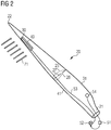
- shows a rotor blade of a wind turbine with an aerodynamic device, which is operatable according to the present invention;
- Figure 3
- show a first radial section of the rotor blade of
figure 2 ; - Figure 4
- show a second radial section of the rotor blade of
figure 2 . - The drawings are in schematic form. Similar or identical elements are referenced by the same or different reference signs.
-
Figure 1 shows aconventional wind turbine 10 for generating electricity. Thewind turbine 10 comprises atower 11 which is mounted on theground 16 at one end. At the opposite end of thetower 11 there is mounted anacelle 12. Thenacelle 12 is usually mounted rotatable with regard to thetower 11, which is referred to as comprising a yaw axis substantially perpendicular to theground 16. Thenacelle 12 usually accommodates the generator of the wind turbine and the gear box (if the wind turbine is a geared wind turbine). Furthermore, thewind turbine 10 comprises ahub 13 which is rotatable about a rotor axis Y. When not differently specified, the terms axial, radial and circumferential in the following are made with reference to the rotor axis Y.
Thehub 13 is often described as being a part of a wind turbine rotor, wherein the wind turbine rotor is capable to rotate about the rotor axis Y and to transfer the rotational energy to an electrical generator (not shown). - The wind turbine 1 further comprises at least one blade 20 (in the embodiment of
Figure 1 , the wind rotor comprises threeblades 20, of which only twoblades 20 are visible) mounted on thehub 13. The blades 4 extend substantially radially with respect to the rotational axis Y.
Eachrotor blade 20 is usually mounted pivotable to thehub 13, in order to be pitched about respective pitch axes X. This improves the control of the wind turbine and in particular of the rotor blades by the possibility of modifying the direction at which the wind is hitting therotor blades 20. Eachrotor blade 20 is mounted to thehub 13 at itsroot section 21. Theroot section 21 is opposed to thetip section 22 of the rotor blade. -
Figure 2 illustrates therotor blade 20 comprising anaerodynamic device 30 in the form of an actuated spoiler. Between theroot section 21 and thetip section 22 therotor blade 20 furthermore comprises a plurality of aerofoil sections for generating lift. Each aerofoil section comprises asuction side 25 and apressure side 26. The aerofoil shape of the aerofoil portion is symbolized by one aerofoil profile which is shown inFigure 2 and which illustrates the cross-sectional shape of the rotor blade at this spanwise position. Also note that thesuction side 25 is divided or separated from thepressure side 26 by achord line 27 which connects aleading edge 41 with a trailingedge 31 of therotor blade 20.
Theaerodynamic device 30 inFigure 2 is movable by means of apressure line 53 connected to apneumatic actuator 34. According to the embodiment of the attached figures, thepneumatic actuator 34 is realized as a hose. Thehose 34 comprises an elastic outer skin, such that it can inflate and deflate reversibly and during many cycles when operated by means of thepressure line 53. - The
pressure line 53 is comprised in apressure supply system 52 and controlled by acontrol unit 51. Thepressure supply system 52 provides pressurized air, for example pressurized air or other pressurized gas, to thepneumatic actuator 34. In this context, the term "pressurized fluid" not only implies positive pressure but also negative pressure, wherein fluid is sucked (or "drawn") out of thepneumatic actuator 34. Thepressure line 53 could be in practice realized as tubes or pipes which do not significantly change their volume. Thecontrol unit 51 is responsible for setting a specific pressure at thepressure supply system 52 which subsequently leads to a certain predetermined pressure at thepneumatic actuator 34. By controlling the pressure of the pressurized air thepneumatic actuator 34 is operated between an inflated and a deflated configuration.
According to different embodiments of the present invention, any of thecontrol unit 51 and thepressure supply system 52 may be located in theroot section 21 of therotor blade 20 or placed elsewhere in the wind turbine, such as e.g. in thehub 13 of thewind turbine 10 or in thenacelle 12 or in thetower 11.
Therotor blade 20 additionally comprises aflow regulating unit 40 comprising multiple pairs of vortex generators.
Theflow regulating unit 40 are arranged on thesuction side 25 of theblade 20 between theaerodynamic device 30 and the the trailingedge 31.
According to other embodiments of the present invention (not shown in the attached figures), theflow regulating unit 40 are arranged on thesuction side 25 of theblade 20 between theleading edge 41 and theaerodynamic device 30.
According to other embodiments of the present invention (not shown in the attached figures), theflow regulating unit 40 are not present and only theaerodynamic device 30 is used to regulate the flow on the surface of theblade 20.
According to other embodiments of the present invention (not shown in the attached figures), theblade 20 comprises a plurality ofaerodynamic devices 30.
According to other embodiments of the present invention (not shown in the attached figures), theaerodynamic device 30 are configured as a trailing edge flap.
According to other embodiments of the present invention (not shown in the attached figures), theblade 20 may comprise a plurality ofaerodynamic devices 30 including flaps and spoilers.
Therotor blade 20 additionally comprises onesensor 54 for measuring vibrations of therotor blade 20. Thesensor 54 is connected to thecontrol unit 51 for transmitting a vibration signal.
According to other embodiments of the present invention (not shown in the attached figures), theblade 20 may comprise a plurality ofvibrations sensor 54, distributed along therotor blade 20.
Thecontrol unit 51 elaborates the vibration signal from thesensors 54 to determine a vibration of therotor blade 20 in the chordwise (edgewise) direction. -
Figure 3 shows theaerodynamic device 30 in a first protruded configuration, corresponding to an inflated configuration of thepneumatic actuator 34.
In the first configuration theaerodynamic device 30 deviates theairflow 71 which is flowing from the leadingedge 41 to the trailingedge 31 of the rotor blade.
Theaerodynamic device 30 in the first protruded configuration induces stall. This is visualized with relativelylarge vortices 63 downstream of theaerodynamic device 30. A consequence of the induced stall is a decrease in lift of the rotor blade and, consequently, a reduced loading of the rotor blade and related components of the wind turbine. -
Figure 4 shows theaerodynamic device 30 in a second retracted configuration, i.e. moved downwards towards the surface of therotor blade 20, corresponding to a deflated configuration of thepneumatic actuator 34.
In this second configuration, theairflow 71 flowing across theaerodynamic device 30 remains attached to the surface of therotor blade 20, thus that no flow separation, i.e. stall, occurs. As a consequence, the lift of the rotor blade increases.Re-energizing vortices 64 are generated in the boundary layer by thevortex generators 40, which have the effect of helping increasing the lift. As a result, the highest lift values can be achieved. - By operating the
pneumatic actuator 34 of theaerodynamic device 30 through thepressure line 53, theaerodynamic device 30 can be moved between the first protruded configuration and the second retracted configuration in order to vary the aerodynamic properties of the blade as desired and requested when operating thewind turbine 10. - According to the method of the present invention, the
pneumatic actuator 34 operates theaerodynamic device 30 for removing vibrations in therotor blade 20.
The method comprises the step of: - measuring vibrations of the
rotor blade 20, through thesensors 54 provided on therotor blade 20, and - operating the
aerodynamic device 30 so that the geometry of the surface of therotor blade 20 is changed and the oscillations reduced.
The frequency of the cyclic load caused by the wind is changed or removed.
Different active aerodynamic devices can be used for the purposes of the present invention.
According to embodiments of the present invention, the aerodynamic device is an active flap, i.e. an aerodynamic device installed at the trailing edge of the rotor blade. Alternatively, the aerodynamic device is an active spoiler, i.e. an aerodynamic device installed in a position intermediate between the leading edge and the trailing edge of the rotor blade.
According to embodiments of the present invention, flaps and spoilers are together provided on the rotor blade and both types of aerodynamic devices may be used to remove vibrations in the rotor blade, according to the present invention.
Claims (8)
- Wind turbine (10) including:- at least one rotor blade (20) comprising an aerodynamic device (30) for influencing the airflow (61) flowing from the leading edge section (24) of the rotor blade (20) to the trailing edge section (23) of the rotor blade (20), wherein the aerodynamic device (30) is mounted at a surface (28) of the rotor blade (20),- an actuator (34) for operating the aerodynamic device (30) between a first protruded configuration and a second retracted configuration,- a control unit (51) for controlling the actuator (34),- at least one sensor (54) for measuring vibrations of the rotor blade (20), the sensor (54) being connected to the control unit (51),wherein the monitor unit (54) is configured for:- receiving a vibration signal from the sensor (54),- controlling the actuator (34) for operating the aerodynamic device (30) so that the geometry of the surface of the rotor blade (20) is changed and the oscillations damped.
- Wind turbine (10) according to claim 1, wherein the sensor (54) measures oscillations of the rotor blade (20) in the chordwise direction.
- Wind turbine (10) according to claim 1 or 2, wherein the aerodynamic device (30) is a flap.
- Wind turbine (10) according to any of the preceding claims, wherein the aerodynamic device (30) is a spoiler.
- Method for removing vibrations in a rotor blade (20) for a wind turbine (10), the rotor blade (20) comprising an aerodynamic device (30) for influencing the airflow (61) flowing from the leading edge section (24) of the rotor blade (20) to the trailing edge section (23) of the rotor blade (20), wherein the aerodynamic device (30) is mounted at a surface (28) of the rotor blade (20), the aerodynamic device (30) being movable by an actuator between a first protruded configuration and a second retracted configuration, the method comprising the steps of:- measuring vibrations of the rotor blade (20),- operating the aerodynamic device (30) so that the geometry of the surface of the rotor blade (20) is changed and the oscillations reduced.
- Method according to claim 5, wherein oscillations of the rotor blade (20) are measured in the chordwise direction.
- Method according to claim 5 or 6, wherein the method is applied during a stand still operational state.
- Method according to claim 5 or 6, wherein the method is applied during a connection loss between the wind turbine (10) and an electrical grid to which the wind turbine (10) is connected.
Priority Applications (1)
| Application Number | Priority Date | Filing Date | Title |
|---|---|---|---|
| EP18212371.1A EP3667065A1 (en) | 2018-12-13 | 2018-12-13 | Removing vibrations in wind turbine blades |
Applications Claiming Priority (1)
| Application Number | Priority Date | Filing Date | Title |
|---|---|---|---|
| EP18212371.1A EP3667065A1 (en) | 2018-12-13 | 2018-12-13 | Removing vibrations in wind turbine blades |
Publications (1)
| Publication Number | Publication Date |
|---|---|
| EP3667065A1 true EP3667065A1 (en) | 2020-06-17 |
Family
ID=64665457
Family Applications (1)
| Application Number | Title | Priority Date | Filing Date |
|---|---|---|---|
| EP18212371.1A Withdrawn EP3667065A1 (en) | 2018-12-13 | 2018-12-13 | Removing vibrations in wind turbine blades |
Country Status (1)
| Country | Link |
|---|---|
| EP (1) | EP3667065A1 (en) |
Citations (3)
| Publication number | Priority date | Publication date | Assignee | Title |
|---|---|---|---|---|
| EP2128385A2 (en) * | 2008-05-16 | 2009-12-02 | Frontier Wind, LLC. | Wind turbine with deployable air deflectors |
| WO2013087468A1 (en) * | 2011-12-15 | 2013-06-20 | Lm Wind Power A/S | A wind turbine blade control method |
| US20130195657A1 (en) * | 2010-06-30 | 2013-08-01 | Vestas Wind Systems A/S | Wind turbine system for detection of blade icing |
-
2018
- 2018-12-13 EP EP18212371.1A patent/EP3667065A1/en not_active Withdrawn
Patent Citations (3)
| Publication number | Priority date | Publication date | Assignee | Title |
|---|---|---|---|---|
| EP2128385A2 (en) * | 2008-05-16 | 2009-12-02 | Frontier Wind, LLC. | Wind turbine with deployable air deflectors |
| US20130195657A1 (en) * | 2010-06-30 | 2013-08-01 | Vestas Wind Systems A/S | Wind turbine system for detection of blade icing |
| WO2013087468A1 (en) * | 2011-12-15 | 2013-06-20 | Lm Wind Power A/S | A wind turbine blade control method |
Non-Patent Citations (1)
| Title |
|---|
| ANDERSEN P B ET AL: "Deformable trailing edge flaps for modern megawatt wind turbine controllers using strain gauge sensors", WIND ENERGY, WILEY, CHICHESTER, GB, vol. 13, no. 2-3, 9 December 2009 (2009-12-09), pages 193 - 206, XP002692909, ISSN: 1099-1824, [retrieved on 20091209], DOI: 10.1002/WE.371 * |
Similar Documents
| Publication | Publication Date | Title |
|---|---|---|
| CN101354008B (en) | Wind turbine blade with cambering flaps | |
| EP2425129B1 (en) | Wind turbine rotor blade | |
| EP3577339B1 (en) | Pressure supply system for a pneumatically activatable aerodynamic device of a rotor blade of a wind turbine | |
| EP2034178A2 (en) | Wind turbine blade with deflectable flaps | |
| US10677217B2 (en) | Wind turbine and method of operating the same | |
| EP2141357A1 (en) | A wind turbine blade | |
| US11767822B2 (en) | Wind turbine blade flow regulation | |
| EP3870845B1 (en) | Damping vibrations in a wind turbine | |
| WO2022008302A1 (en) | Rotor blade assembly for mitigating stall-induced vibrations | |
| EP3667065A1 (en) | Removing vibrations in wind turbine blades | |
| EP4100645B1 (en) | Aerodynamic load reduction during blade installation and service in a wind turbine | |
| WO2018145715A1 (en) | Method and system for controlling a wind turbine | |
| EP4305297A1 (en) | Operating a wind turbine for wake control | |
| EP3580453B1 (en) | Method and system for controlling a wind turbine | |
| EP3667080A1 (en) | Wind turbine blade flow regulation | |
| EP3867526B1 (en) | Wind turbine blade flow regulation | |
| EP3867521B1 (en) | Wind turbine | |
| EP3832127A1 (en) | Wind turbine blade flow regulation |
Legal Events
| Date | Code | Title | Description |
|---|---|---|---|
| PUAI | Public reference made under article 153(3) epc to a published international application that has entered the european phase |
Free format text: ORIGINAL CODE: 0009012 |
|
| STAA | Information on the status of an ep patent application or granted ep patent |
Free format text: STATUS: THE APPLICATION HAS BEEN PUBLISHED |
|
| AK | Designated contracting states |
Kind code of ref document: A1 Designated state(s): AL AT BE BG CH CY CZ DE DK EE ES FI FR GB GR HR HU IE IS IT LI LT LU LV MC MK MT NL NO PL PT RO RS SE SI SK SM TR |
|
| AX | Request for extension of the european patent |
Extension state: BA ME |
|
| STAA | Information on the status of an ep patent application or granted ep patent |
Free format text: STATUS: THE APPLICATION IS DEEMED TO BE WITHDRAWN |
|
| 18D | Application deemed to be withdrawn |
Effective date: 20201218 |