EP2425129B1 - Wind turbine rotor blade - Google Patents
Wind turbine rotor blade Download PDFInfo
- Publication number
- EP2425129B1 EP2425129B1 EP10718896.3A EP10718896A EP2425129B1 EP 2425129 B1 EP2425129 B1 EP 2425129B1 EP 10718896 A EP10718896 A EP 10718896A EP 2425129 B1 EP2425129 B1 EP 2425129B1
- Authority
- EP
- European Patent Office
- Prior art keywords
- wind turbine
- turbine blade
- trailing edge
- blade
- blade according
- Prior art date
- Legal status (The legal status is an assumption and is not a legal conclusion. Google has not performed a legal analysis and makes no representation as to the accuracy of the status listed.)
- Not-in-force
Links
Images


Classifications
-
- F—MECHANICAL ENGINEERING; LIGHTING; HEATING; WEAPONS; BLASTING
- F03—MACHINES OR ENGINES FOR LIQUIDS; WIND, SPRING, OR WEIGHT MOTORS; PRODUCING MECHANICAL POWER OR A REACTIVE PROPULSIVE THRUST, NOT OTHERWISE PROVIDED FOR
- F03D—WIND MOTORS
- F03D1/00—Wind motors with rotation axis substantially parallel to the air flow entering the rotor
- F03D1/06—Rotors
- F03D1/0608—Rotors characterised by their aerodynamic shape
- F03D1/0633—Rotors characterised by their aerodynamic shape of the blades
- F03D1/0641—Rotors characterised by their aerodynamic shape of the blades of the section profile of the blades, i.e. aerofoil profile
-
- F—MECHANICAL ENGINEERING; LIGHTING; HEATING; WEAPONS; BLASTING
- F03—MACHINES OR ENGINES FOR LIQUIDS; WIND, SPRING, OR WEIGHT MOTORS; PRODUCING MECHANICAL POWER OR A REACTIVE PROPULSIVE THRUST, NOT OTHERWISE PROVIDED FOR
- F03D—WIND MOTORS
- F03D7/00—Controlling wind motors
- F03D7/02—Controlling wind motors the wind motors having rotation axis substantially parallel to the air flow entering the rotor
- F03D7/0244—Controlling wind motors the wind motors having rotation axis substantially parallel to the air flow entering the rotor for braking
-
- F—MECHANICAL ENGINEERING; LIGHTING; HEATING; WEAPONS; BLASTING
- F03—MACHINES OR ENGINES FOR LIQUIDS; WIND, SPRING, OR WEIGHT MOTORS; PRODUCING MECHANICAL POWER OR A REACTIVE PROPULSIVE THRUST, NOT OTHERWISE PROVIDED FOR
- F03D—WIND MOTORS
- F03D7/00—Controlling wind motors
- F03D7/02—Controlling wind motors the wind motors having rotation axis substantially parallel to the air flow entering the rotor
- F03D7/022—Adjusting aerodynamic properties of the blades
- F03D7/0232—Adjusting aerodynamic properties of the blades with flaps or slats
-
- F—MECHANICAL ENGINEERING; LIGHTING; HEATING; WEAPONS; BLASTING
- F03—MACHINES OR ENGINES FOR LIQUIDS; WIND, SPRING, OR WEIGHT MOTORS; PRODUCING MECHANICAL POWER OR A REACTIVE PROPULSIVE THRUST, NOT OTHERWISE PROVIDED FOR
- F03D—WIND MOTORS
- F03D7/00—Controlling wind motors
- F03D7/02—Controlling wind motors the wind motors having rotation axis substantially parallel to the air flow entering the rotor
- F03D7/04—Automatic control; Regulation
-
- F—MECHANICAL ENGINEERING; LIGHTING; HEATING; WEAPONS; BLASTING
- F05—INDEXING SCHEMES RELATING TO ENGINES OR PUMPS IN VARIOUS SUBCLASSES OF CLASSES F01-F04
- F05B—INDEXING SCHEME RELATING TO WIND, SPRING, WEIGHT, INERTIA OR LIKE MOTORS, TO MACHINES OR ENGINES FOR LIQUIDS COVERED BY SUBCLASSES F03B, F03D AND F03G
- F05B2240/00—Components
- F05B2240/20—Rotors
- F05B2240/30—Characteristics of rotor blades, i.e. of any element transforming dynamic fluid energy to or from rotational energy and being attached to a rotor
- F05B2240/305—Flaps, slats or spoilers
- F05B2240/3052—Flaps, slats or spoilers adjustable
-
- F—MECHANICAL ENGINEERING; LIGHTING; HEATING; WEAPONS; BLASTING
- F05—INDEXING SCHEMES RELATING TO ENGINES OR PUMPS IN VARIOUS SUBCLASSES OF CLASSES F01-F04
- F05B—INDEXING SCHEME RELATING TO WIND, SPRING, WEIGHT, INERTIA OR LIKE MOTORS, TO MACHINES OR ENGINES FOR LIQUIDS COVERED BY SUBCLASSES F03B, F03D AND F03G
- F05B2240/00—Components
- F05B2240/20—Rotors
- F05B2240/30—Characteristics of rotor blades, i.e. of any element transforming dynamic fluid energy to or from rotational energy and being attached to a rotor
- F05B2240/31—Characteristics of rotor blades, i.e. of any element transforming dynamic fluid energy to or from rotational energy and being attached to a rotor of changeable form or shape
- F05B2240/311—Characteristics of rotor blades, i.e. of any element transforming dynamic fluid energy to or from rotational energy and being attached to a rotor of changeable form or shape flexible or elastic
-
- F—MECHANICAL ENGINEERING; LIGHTING; HEATING; WEAPONS; BLASTING
- F05—INDEXING SCHEMES RELATING TO ENGINES OR PUMPS IN VARIOUS SUBCLASSES OF CLASSES F01-F04
- F05B—INDEXING SCHEME RELATING TO WIND, SPRING, WEIGHT, INERTIA OR LIKE MOTORS, TO MACHINES OR ENGINES FOR LIQUIDS COVERED BY SUBCLASSES F03B, F03D AND F03G
- F05B2270/00—Control
- F05B2270/10—Purpose of the control system
- F05B2270/109—Purpose of the control system to prolong engine life
- F05B2270/1095—Purpose of the control system to prolong engine life by limiting mechanical stresses
-
- Y—GENERAL TAGGING OF NEW TECHNOLOGICAL DEVELOPMENTS; GENERAL TAGGING OF CROSS-SECTIONAL TECHNOLOGIES SPANNING OVER SEVERAL SECTIONS OF THE IPC; TECHNICAL SUBJECTS COVERED BY FORMER USPC CROSS-REFERENCE ART COLLECTIONS [XRACs] AND DIGESTS
- Y02—TECHNOLOGIES OR APPLICATIONS FOR MITIGATION OR ADAPTATION AGAINST CLIMATE CHANGE
- Y02E—REDUCTION OF GREENHOUSE GAS [GHG] EMISSIONS, RELATED TO ENERGY GENERATION, TRANSMISSION OR DISTRIBUTION
- Y02E10/00—Energy generation through renewable energy sources
- Y02E10/70—Wind energy
- Y02E10/72—Wind turbines with rotation axis in wind direction
Definitions
- the present invention relates to a wind turbine rotor blade.
- wind turbine blades having devices for modifying the aerodynamic surface and camber of the blade in order to alleviate loads acting on the wind turbine rotor.
- Modern wind turbines are controlled during operation in order to optimise the performance of the wind turbine in different operating conditions.
- the different operating conditions can arise from changes in wind speed and wind gusts which are local fast variations in wind speed.
- Wind turbines are subjected to loads of a highly variable nature due to the wind conditions.
- the pitch can be used not only for controlling the speed of the rotor, but also for reducing the variations in load on the blades.
- the blade pitch mechanisms are not ideal for reacting rapidly to variations in wind speed which occur over a short time frame.
- the length of wind turbine blades is increasing with new technology and the blades are becoming more flexible due to their greater length.
- wind turbine rotors are subjected to a variety of loads. These can be generalised into two categories:
- the low frequency high amplitude loads arise from wind shear (the increase in speed of the wind with the height above the ground), the yaw error (a cross-flow of wind towards the rotor when the rotor axis is not aligned with the wind direction), and tower shadow (the interference caused by the retardation of the flow due to the tower on which the rotor is mounted via a nacelle).
- the high frequency low amplitude loads arise from turbulence and blade vibrations, for example.
- US2009/0074573 describes a wind turbine blade having a flap for optimising blade loads.
- the flap is controlled through an actuating force which is a measured change in wind pressure that is scaled.
- WO2004/088130 describes a wind turbine blade with variable geometry that may be controlled though smart materials.
- An object of the present invention is to provide a rotor blade that can alleviate both the low frequency high amplitude loads and the high frequency low amplitude loads.
- the invention overcomes the problems associated with the prior art because the first device alleviates the low frequency high amplitude loads and the second device alleviates the high frequency low amplitude loads.
- the camber, or mean camber line, of an airfoil section is the curvature which is defined by a line halfway between the upper and lower surfaces of the airfoil section.
- the camber of an airfoil section affects air flow over the airfoil and therefore the lift generated by the airfoil.
- a device affects the airflow over the airfoil without changing the physical geometry of the airfoil section, it is referred to a change in the effective camber.
- the second device for modifying the effective camber of the airfoil cross section may modify the aerodynamic surface or shape of the blade and the position and/or movement of the second device relative to the blade body may be controlled by a second actuation mechanism.
- the first device may operate to modify the aerodynamic surface or shape of the blade at a frequency up to 1 Hz.
- the second device may operate to modify the effective camber of the airfoil cross section at a frequency up to 15 Hz.
- the first device may have a chord length between 5% and 50% of the chord length of the wind turbine blade.
- the second device may have a chord length of less than 10% of the chord length of the wind turbine blade.
- the chord length of the first and second device refers to the distance between the edges of the devices in a chordwise direction, i.e. the distance between the front end and a rear end of each device.
- the second device may have a chord length of up to 50% of the chord length of the first device.
- the first device and the second device may be disposed adjacent to each other on the trailing edge.
- the first device and the second device form part of the trailing edge and they may be disposed separate from each other on the trailing edge.
- the first device may form part of the trailing edge and the first device may surround the second device.
- the first device may be a trailing edge flap or a deformable trailing edge.
- the first device and the second device may have: a front end in the direction of the leading edge of the wind turbine blade and a rear end in the direction of the trailing edge of the wind turbine blade; wherein the front end of the first device is connected to the blade body for rotation relative to the blade body; and the front end of the second device is connected to the rear end of the first device for rotation relative to the first device.
- the first actuation mechanism which controls position and/or movement of the first device may be a pneumatic actuation mechanism.
- the first actuation mechanism which controls the position and/or movement of the first device may be a thermoelectric actuator or a shape memory alloy actuator.
- the second device may be a trailing edge flap or a deformable trailing edge.
- the second device may comprise a microtab arranged to project from the surface of the airfoil cross section, the microtab being located within a distance of 10% of the chord length from the trailing edge.
- the second device may comprise a fluid ejection or suction means arranged to eject or suck fluid from the surface of the airfoil cross section within a distance of 10% of the chord length from the trailing edge.
- the second device may comprise electrodes located on an outer surface of the wind turbine blade within a distance of 10% of the chord length from the trailing edge; wherein a voltage is applied across the electrodes to generate plasma between the electrodes.
- a plurality of the first devices are provided in the longitudinal direction of the wind turbine blade.
- a plurality of the second devices are provided in the longitudinal direction of the wind turbine blade.
- the invention may be embodied in a wind turbine generator having at least two blades according to any one of the preceding claims.
- the wind turbine generator is a horizontal axis wind turbine generator.
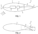
- FIG. 1 shows a first example of a cross-section of a wind turbine blade.
- the blade section 10 is formed, in this first example, from a blade body 11, a slow morphing part 12 and a fast trailing edge flap 13.
- the morphing part 12 is a first device and the trailing edge flap 13 is a second device.
- the leading edge of the blade is identified as 14, the trailing edge by 15, the pressure side by 16 and the suction side by 17.
- a pitot tube 18 for monitoring the local pressure, relative wind speed and angle of attack at the blade section 10 is provided at the leading edge 14 of the blade section 10.
- a controller 19 is provided within the blade section for signal collection from the pitot tube 18.
- An actuator power control unit is shown at 20 for providing power to actuators (not shown) for moving the morphing part 12 and the trailing edge flap 13.
- Figure 2 shows how the morphing part 12 and the trailing edge flap 13 can be operated during use.
- the morphing part 12 deflects relative to the blade body 11 and the trailing edge flap 13 deflects relative to the morphing part 12 and the blade body 11.
- a front end of the morphing part 12 is connected directly to the blade body 11 and deflects relative to the blade body.
- the trailing edge flap 13 is mounted at a front end to the rear end of the morphing part 12 and deflects relative to the morphing part.
- the blade body 11 is a rigid part of the wind turbine blade 11 and may form part of a structural spar.
- the chord length of morphing part 12 is, in this example, 30% of the chord length of the blade section 10.
- the chord length of the trailing edge flap 13 is, in this example, 5% of the chord length of the blade section 10.
- the morphing part 12 operates at a frequency of 0.1 Hz, but could operate at a frequency up to 1 Hz.
- the morphing part 12 operates with a range of movement of +/- 15 degrees about its equilibrium position, but could operate with a range of movement of +/- 25 degrees about its equilibrium position.
- the trailing edge flap 13 operates at frequency of up to 10 Hz with a movement of three degrees each way of its equilibrium position.
- C L x V 2 is a good approximation. However, it also depends on the angle of attack (alpha) of the blade, in which case it is desirable to keep L'cos(alpha)+D'sin(alpha) constant and D'cos(alpha)-L'sin(alpha) constant. (Where L' is the lift force on the local blade section and D' is the drag force on the local blade section).
- the controller 19 will calculate, for the current wind conditions, how the morphing part 12 and the trailing edge flap 13 should be deflected to keep the loads acting on the blade section or the entire blade constant.
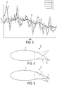
- Figure 3 shows a graph plotting time on the x axis against C L x V 2 on the y axis during normal high wind conditions:
- the trailing edge flaps 13 are efficient to alleviate high frequency low amplitude variations. But, the trailing edge flaps 13 are not efficient enough to alleviate high amplitude variations and as can be seen from line 31, the trailing edge flaps cannot make C L x V 2 constant during high amplitudes variations. However, these high amplitude variations have a 1P frequency and arise from wind shear, yaw error or tower shadow and are predictable. By using the morphing part 12 of the blade at a 1P frequency, these peaks are removed.
- the y axis of Figure 3 represents the parameter C L x V 2 .
- this parameter could be any parameter that is alleviated, such as the wind turbine blade flap root moment, the blade mid-span moment, or the lift coefficient for the whole blade.
- the morphing part 12 is slow moving and is thus also more reliable compared to a fast moving component having a similar chord and amplitude of motion.
- 'reliable' it is meant that the morphing part 12 and the trailing edge flap 13 are able to last longer in operation in a wind turbine before they, or associated components, need to be replaced.
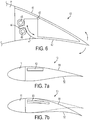
- the morphing part 12 When the wind turbine is in a parked condition, that is when the rotor is not turning (for instance due to high wind) the morphing part 12 can be locked as shown in Figure 4 and the trailing edge flap 13 is not actuated. By placing the morphing part 12 in this position, the lift of the blade section 10 is reduced so that extreme loads acting on the turbine (for instance from gusts and high wind) are reduced.
- Figure 5 shows how the morphing part 12 is used to increase the camber line of the blade section 10 in order to obtain a high lift profile. This decreases the cut in wind speed and increases the power production.
- the morphing part 12 is moved to the position where it generates maximum lift (and it may be locked in this position) and the trailing edge flap 13 can also be used to alleviate small fluctuations in loads acting on the rotor.
- the morphing part 12 is actuated by means of pneumatics as illustrated in Figure 6 (the trailing edge flap 13 is omitted in Figure 6 for clarity).
- the morphing part 12 comprises a pressure skin 41 formed from a flexible material so that the blade profile maintains a smooth upper surface when the morphing part 12 is deflected.
- the morphing part 12 is movably connected to the blade body 11 and can be rotated about a hinge 43.
- a lever element or vane 44 is disposed between two pressure chambers 45 and 46. When the chamber 45 is pressurised and the chamber 46 is depressurised, the lever element 44 is forced downwards according to the orientation in Figure 6 . This applies a rotational motion to the morphing part to deflect it upwards about the hinge 43.
- the lever element 44 When the chamber 45 is depressurised and the chamber 46 is pressurised, the lever element 44 is forced upwards according to the orientation in Figure 6 . This applies a rotational motion to the morphing part to deflect it downwards about the hinge 43. As shown in Figure 6 , a radial surface 47 with its centre in the rotation hinge 43 is provided to enable the morphing part 12 to move while maintaining the continuity of the lower blade skin 42 when the morphing part is actuated.
- the chambers 45 and 46 may be in the form of thermoplastic hoses disposed along the longitudinal axis of the wind turbine blade.
- the trailing edge flap 13 is actuated by a motor (not shown) to cause the trailing edge flap 13 to rotate relative to the blade body 11 and relative to the morphing part 12.
- the trailing edge flap 13 could also be caused to deflect by means of a piezoelectric actuator.
- thermoelectric actuator 50 is used in order to modify the aerodynamic cross section of the blade section 10 - this provides the morphing part of the blade section 10 which alleviates the low frequency high amplitude loads and vibrations.
- a voltage is applied across the thermoelectric actuator which causes it to contract ( Figure 7a ) or stretch ( Figure 7b ) as a current flow produces heating, which imparts large thermal stresses causing the thermoelectric actuator to change shape.
- An upper skin 51 and a lower skin 52 are connected by means (not shown) to the thermoelectric actuator 50 such that when the thermoelectric actuator changes shape, the blade profile changes, so that the camber of the blade section 10 changes.
- thermoelectric actuator 50 and the upper and lower skins 51 and 52 form the morphing part, being the equivalent of the morphing part 12 in the first example.
- a shape memory alloy (SMA) could also be used to change the blade shape in place of the thermoelectric actuator.
- thermoelectric actuator 50 or SMA will modify the shape and aerodynamic surface of the blade at the same frequency as the morphing part described in Figure 1 , that is between 0.1 Hz to 1 Hz.
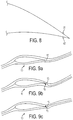
- FIG 8 illustrates, in a third example, how microtabs 61 and 62 can be used in place of a trailing edge flap in order to alleviate the high frequency small amplitude loads.
- the microtab (or micro-electrical mechanical tab, MEM) is a small tab that projects from the blade surface in the region of the trailing edge 15.
- the microtab projects substantially perpendicular to the blade surface and can be actuated so that they slide out of the blade 10 and project to a height which is approximately the thickness of the boundary layer.
- a microtab deployment on the suction side of the blade 10 causes a decrease in the lift coefficient whereas a deployment on the pressure side causes an increase in the lift coefficient. This change in lift coefficient is due to the microtabs 61 and 62 modifying the effective camber of the blade section 10.
- microtabs 61 and 62 will modify the effective camber of the blade section 10 at the same frequency as the trailing edge flap described in Figure 1 , that is up to 10 Hz.
- Figures 9a, 9b and 9c show, in a fourth example, how jets 70 and 71 are used in place of a trailing edge flap in order to alleviate the high frequency small amplitude loads.
- a hole (not shown) is provided in the vicinity of the trailing edge 15 of the blade section 10 through which a jet of air is ejected or blown in order to modify the effective camber of the blade section.
- Figure 9a illustrates typical streamline around the blade section in a reference case without blowing.
- Figure 9b illustrates the jet 70 on the pressure side of the blade section 10 blowing and it can be seen that the effective camber line is shifted to generate higher lift.
- Figure 9c illustrates the jet 71 on the suction side of the blade section 10 blowing and the effective camber line is shifted to generate lower lift. It is also possible to modify the effective camber line by using suction instead of jets.
- the jets 70 and 71 will modify the effective camber of the blade section 10 at the same frequency as the trailing edge flap described in Figure 1 , that is up to 10 Hz.
- a plasma actuator may be used in place of the trailing edge flap 13.
- Plasma actuators generate an "electric wind" between their electrodes.
- electrodes 80a and 80b are provided on the suction side of the blade section in the vicinity of the trailing edge and electrodes 81a and 82b are provided on the pressure side of the blade section in the vicinity of the trailing edge.
- a plasma is formed generating an "electric wind" as illustrated by arrows 82 which will affect the lift generation of the blade section 10 by modifying the effective camber line.
- the electrodes are shown in Figures 10a and 10b in the vicinity of the trailing edge, but they could also be provided at the forward end (i.e. towards the leading edge direction) of the morphing part 12.
- the plasma generated by the electrodes will modify the effective camber of the blade section 10 at the same frequency as the trailing edge flap described in Figure 1 , that is up to 10 Hz.
- Figures 11a to 11e illustrate examples of the arrangement of the morphing part 12 and the trailing edge flap 13 on a rotor blade 1.
- the rotor blade 1 has a root end 2 which is connected to a hub (not shown) of a wind turbine nacelle and a tip end 3.
- Figure 11a illustrates one morphing part 12 with four trailing edge flaps 13.
- Figure 11b illustrates two morphing parts 12 each surrounding two trailing edge flaps 13.
- Figure 11c illustrates four morphing parts 12 each surrounding one trailing edge flap 13.
- Figure 11d illustrates one morphing part 12 near the root end 2 of the blade 1 with four morphing parts 12 each surrounding one trailing edge flap 13 near the tip end 3 of the blade 1.
- the zones between the morphing parts 12 and the trailing edge flaps 13 have smooth transitions which are provided by a flexible skin material such as rubber or silicone.
- a flexible overlapping geometry between the morphing parts 12 and the trailing edge flaps 13 may also be provided.
- the trailing edge flaps 13 are shown to be surrounded by the morphing part 12. However the morphing part 12 and the trailing edge flap 13 may be separated by placing them side by side along the trailing edge of the blade 1 as shown in Figure 11e , but the part of the blade 1 where the trailing edge flap 13 is placed should be affected by the geometry of the blade resulting from the morphing part 12 to still have the combined action of fast and slow moving actuation.
- the trailing edge flap 13 integration into the morphing part 12 may be similar to the integration into the normal blade body 11, since the morphing part 12 should actuate on the bigger structure of the blade body 11.
- Figures 11a to 11e have been described with reference to the morphing part 12 and the trailing edge flap 13, these can be replaced with any of the other examples described in relation to Figures 7 , 8 , 9 or 10 .
Landscapes
- Engineering & Computer Science (AREA)
- Life Sciences & Earth Sciences (AREA)
- Sustainable Development (AREA)
- Sustainable Energy (AREA)
- Chemical & Material Sciences (AREA)
- Combustion & Propulsion (AREA)
- Mechanical Engineering (AREA)
- General Engineering & Computer Science (AREA)
- Physics & Mathematics (AREA)
- Fluid Mechanics (AREA)
- Wind Motors (AREA)
Description
- The present invention relates to a wind turbine rotor blade. In particular it relates to wind turbine blades having devices for modifying the aerodynamic surface and camber of the blade in order to alleviate loads acting on the wind turbine rotor.
- Modern wind turbines are controlled during operation in order to optimise the performance of the wind turbine in different operating conditions. The different operating conditions can arise from changes in wind speed and wind gusts which are local fast variations in wind speed. It is well known to regulate the speed of rotation of the rotor of a horizontal axis wind turbine by pitching the blades of the rotor. This is typically achieved by turning the blades about their longitudinal axis to influence the aerodynamic angle of attack of the rotor blades, this is the method used in pitch controlled wind turbine and active stall controlled wind turbines.
- Wind turbines are subjected to loads of a highly variable nature due to the wind conditions. In modern wind turbines, as the rotor is typically able to control its pitch angle, the pitch can be used not only for controlling the speed of the rotor, but also for reducing the variations in load on the blades. However, due to the large length of modern wind turbine blades and the associated high inertia of the masses to be rotated about a pitch axis, the blade pitch mechanisms are not ideal for reacting rapidly to variations in wind speed which occur over a short time frame. In addition the length of wind turbine blades is increasing with new technology and the blades are becoming more flexible due to their greater length. Consequently, with the length of wind turbine blades increasing, when the blades are pitched there is a longer time lag for the pitch to change at the tip where the main loads are on the blades. Furthermore, controlling the loads on the blades with the use of a pitch system can be problematic as the blade pitch bearings become damaged with constant use.
- It is possible to regulate the loads acting on the blades of a wind turbine rotor with devices which modify the aerodynamic surface or shape of the blades such as by deformable trailing edges or adjustable flaps which can include trailing edge flaps, leading edge flaps, ailerons, spoilers, slats and gurney flaps. Such aerodynamic devices are advantageous because they allow a faster response time due to their relatively low inertia as they are small compared to the size of the entire wind turbine blade. One such example of a wind turbine blade which has a deformable trailing edge is described in
WO2008/132235 . However, flaps themselves have their limits because they cannot alleviate all the loads as their influence on the change of lift on the blade is small. - As mentioned above, wind turbine rotors are subjected to a variety of loads. These can be generalised into two categories:
- low frequency high amplitude loads (so called 1P vibrations); and
- high frequency low amplitude loads.
- The low frequency high amplitude loads arise from wind shear (the increase in speed of the wind with the height above the ground), the yaw error (a cross-flow of wind towards the rotor when the rotor axis is not aligned with the wind direction), and tower shadow (the interference caused by the retardation of the flow due to the tower on which the rotor is mounted via a nacelle). The high frequency low amplitude loads arise from turbulence and blade vibrations, for example.
-
US2009/0074573 describes a wind turbine blade having a flap for optimising blade loads. The flap is controlled through an actuating force which is a measured change in wind pressure that is scaled.WO2004/088130 describes a wind turbine blade with variable geometry that may be controlled though smart materials. - A disadvantage of devices such as trailing edge flaps is that they are not efficient to alleviate the high amplitude vibrations that result from the low frequency high amplitude loads. An object of the present invention is to provide a rotor blade that can alleviate both the low frequency high amplitude loads and the high frequency low amplitude loads.
- According to the present invention there is provided a wind turbine blade in accordance with
claim 1. - The invention overcomes the problems associated with the prior art because the first device alleviates the low frequency high amplitude loads and the second device alleviates the high frequency low amplitude loads.
- The camber, or mean camber line, of an airfoil section is the curvature which is defined by a line halfway between the upper and lower surfaces of the airfoil section. The camber of an airfoil section affects air flow over the airfoil and therefore the lift generated by the airfoil. However, according to the invention, if a device affects the airflow over the airfoil without changing the physical geometry of the airfoil section, it is referred to a change in the effective camber.
- The second device for modifying the effective camber of the airfoil cross section may modify the aerodynamic surface or shape of the blade and the position and/or movement of the second device relative to the blade body may be controlled by a second actuation mechanism.
- The first device may operate to modify the aerodynamic surface or shape of the blade at a frequency up to 1 Hz. The second device may operate to modify the effective camber of the airfoil cross section at a frequency up to 15 Hz.
- The first device may have a chord length between 5% and 50% of the chord length of the wind turbine blade. The second device may have a chord length of less than 10% of the chord length of the wind turbine blade. The chord length of the first and second device refers to the distance between the edges of the devices in a chordwise direction, i.e. the distance between the front end and a rear end of each device. The second device may have a chord length of up to 50% of the chord length of the first device.
- The first device and the second device may be disposed adjacent to each other on the trailing edge.
- The first device and the second device form part of the trailing edge and they may be disposed separate from each other on the trailing edge.
- The first device may form part of the trailing edge and the first device may surround the second device.
- The first device may be a trailing edge flap or a deformable trailing edge.
- The first device and the second device may have: a front end in the direction of the leading edge of the wind turbine blade and a rear end in the direction of the trailing edge of the wind turbine blade; wherein the front end of the first device is connected to the blade body for rotation relative to the blade body; and the front end of the second device is connected to the rear end of the first device for rotation relative to the first device.
- The first actuation mechanism which controls position and/or movement of the first device may be a pneumatic actuation mechanism.
- The first actuation mechanism which controls the position and/or movement of the first device may be a thermoelectric actuator or a shape memory alloy actuator.
- The second device may be a trailing edge flap or a deformable trailing edge.
- The second device may comprise a microtab arranged to project from the surface of the airfoil cross section, the microtab being located within a distance of 10% of the chord length from the trailing edge.
- The second device may comprise a fluid ejection or suction means arranged to eject or suck fluid from the surface of the airfoil cross section within a distance of 10% of the chord length from the trailing edge.
- The second device may comprise electrodes located on an outer surface of the wind turbine blade within a distance of 10% of the chord length from the trailing edge; wherein a voltage is applied across the electrodes to generate plasma between the electrodes.
- Preferably a plurality of the first devices are provided in the longitudinal direction of the wind turbine blade. Preferably, a plurality of the second devices are provided in the longitudinal direction of the wind turbine blade.
- The invention may be embodied in a wind turbine generator having at least two blades according to any one of the preceding claims. Preferably, the wind turbine generator is a horizontal axis wind turbine generator.
- The invention will now be described by way of example with reference to the accompanying drawings in which:
-
Figure 1 illustrates a first example of a cross section of a wind turbine blade; -
Figure 2 illustrates a first example of a cross section of a wind turbine blade; -
Figure 3 is a graph illustrating the effect of the invention on the loads acting on a wind turbine rotor; -
Figure 4 illustrates a cross section of a wind turbine blade in a parked condition; -
Figure 5 illustrates a cross section of a wind turbine blade in a low speed condition; -
Figure 6 illustrates an example of a pneumatic actuator in the vicinity of the trailing edge; -
Figure 7a and 7b illustrate a second example of a cross section of a wind turbine blade; -
Figure 8 illustrates a third example of a cross section of a wind turbine blade in the vicinity of the trailing edge; -
Figures 9a, 9b and 9c illustrate a fourth example of a cross section of a wind turbine blade in the vicinity of the trailing edge; -
Figures 10a and 10b illustrate a fifth example of a cross section of a wind turbine blade; and -
Figures 11a, 11b, 11c, 11d and 11e illustrate a plan view of a wind turbine blade in different configurations. -
Figure 1 shows a first example of a cross-section of a wind turbine blade. Theblade section 10 is formed, in this first example, from ablade body 11, a slow morphingpart 12 and a fasttrailing edge flap 13. In this first example, the morphingpart 12 is a first device and the trailingedge flap 13 is a second device. The leading edge of the blade is identified as 14, the trailing edge by 15, the pressure side by 16 and the suction side by 17. Apitot tube 18 for monitoring the local pressure, relative wind speed and angle of attack at theblade section 10 is provided at theleading edge 14 of theblade section 10. Acontroller 19 is provided within the blade section for signal collection from thepitot tube 18. An actuator power control unit is shown at 20 for providing power to actuators (not shown) for moving the morphingpart 12 and the trailingedge flap 13. -
Figure 2 shows how the morphingpart 12 and the trailingedge flap 13 can be operated during use. The morphingpart 12 deflects relative to theblade body 11 and the trailingedge flap 13 deflects relative to the morphingpart 12 and theblade body 11. In the first example shown inFigure 1 and Figure 2 , a front end of the morphingpart 12 is connected directly to theblade body 11 and deflects relative to the blade body. The trailingedge flap 13 is mounted at a front end to the rear end of the morphingpart 12 and deflects relative to the morphing part. Theblade body 11 is a rigid part of thewind turbine blade 11 and may form part of a structural spar. - The chord length of morphing
part 12 is, in this example, 30% of the chord length of theblade section 10. The chord length of the trailingedge flap 13 is, in this example, 5% of the chord length of theblade section 10. The morphingpart 12 operates at a frequency of 0.1 Hz, but could operate at a frequency up to 1 Hz. The morphingpart 12 operates with a range of movement of +/- 15 degrees about its equilibrium position, but could operate with a range of movement of +/- 25 degrees about its equilibrium position. The trailingedge flap 13 operates at frequency of up to 10 Hz with a movement of three degrees each way of its equilibrium position. - In the first example described in
Figures 1 and 2 a morphingpart 12 and a trailingedge flap 13 are shown, but other devices which cause a change in the camber or the effective camber of the blade are possible, as described in the further examples below. - The lift coefficient CL of a
blade section 10 is defined as:
blade section 10, p is the air density, V is the relative velocity of the blade section in the air flow and C is the chord length of the blade section. - In order to alleviate the loads acting on the
local blade section 10 it is necessary to keep CL x V2 as constant as possible. In the invention, as the relative wind speed experienced by theblade section 10 changes, the lift coefficient of the blade section is changed to compensate. This is achieved by actuating either the morphingpart 12 or the trailingedge flap 13. Actuating either the morphingpart 12 or the trailingedge flap 13 changes the effective camber of theblade section 10 and hence increases or decreases the local lift coefficient. - It should be noted that keeping CL x V2 as constant as possible is a good approximation. However, it also depends on the angle of attack (alpha) of the blade, in which case it is desirable to keep L'cos(alpha)+D'sin(alpha) constant and D'cos(alpha)-L'sin(alpha) constant. (Where L' is the lift force on the local blade section and D' is the drag force on the local blade section).
- Furthermore, this only refers to a local blade section. If the morphing
part 12 and the trailingedge flap 13 are not provided over the span of the entire wind turbine blade, then it is desirable to keep the forces and moments acting on the entire blade as constant as possible. Therefore, the sections of the wind turbine blade with the morphingpart 12 and the trailingedge flap 13 will have to compensate for the variations of loads (forces and moments) in the sections with no morphingparts 12 or trailing edge flaps 13. This means that the objective is no longer trying to keep the forces constant in the local blade sections with the morphingpart 12 and the trailingedge flap 12, but instead changing the lift via the morphingpart 12 and the trailingedge flap 13 to compensate to keep the forces acting on the entire wind turbine blade constant. - The
controller 19 will calculate, for the current wind conditions, how the morphingpart 12 and the trailingedge flap 13 should be deflected to keep the loads acting on the blade section or the entire blade constant. -
Figure 3 shows a graph plotting time on the x axis against CL x V2 on the y axis during normal high wind conditions: -
Line 30 represents CL x V2 against time with no morphingpart 12 or trailingedge flap 13 being actuated. -
Line 31 represents CL x V2 against time with the trailingedge flap 13 being actuated and no morphingpart 12 actuated. -
Line 32 represents CL x V2 against time with the morphingpart 12 being actuated and no trailingedge flap 13 actuated. -
Line 33 represents CL x V2 against time with the trailingedge flap 13 being actuated and the morphingpart 12 actuated. - As can be seen from
Figure 3 , in normal high wind conditions, the trailing edge flaps 13 are efficient to alleviate high frequency low amplitude variations. But, the trailing edge flaps 13 are not efficient enough to alleviate high amplitude variations and as can be seen fromline 31, the trailing edge flaps cannot make CL x V2 constant during high amplitudes variations. However, these high amplitude variations have a 1P frequency and arise from wind shear, yaw error or tower shadow and are predictable. By using the morphingpart 12 of the blade at a 1P frequency, these peaks are removed. - The y axis of
Figure 3 represents the parameter CL x V2. However, this parameter could be any parameter that is alleviated, such as the wind turbine blade flap root moment, the blade mid-span moment, or the lift coefficient for the whole blade. By actuating the morphingpart 12 in combination with the trailingedge flap 13 allows a better alleviation of the loads acting on the rotor. This is because the trailing edge flaps 13 are only designed to alleviate the high frequency small amplitude loads and thus they can have a small chord compared to the chord of theblade section 10 and have a small amplitude of motion - consequently they are more reliable than a large fast moving trailing edge flap with a large degree of movement. The morphingpart 12 is slow moving and is thus also more reliable compared to a fast moving component having a similar chord and amplitude of motion. By 'reliable' it is meant that the morphingpart 12 and the trailingedge flap 13 are able to last longer in operation in a wind turbine before they, or associated components, need to be replaced. - When the wind turbine is in a parked condition, that is when the rotor is not turning (for instance due to high wind) the morphing
part 12 can be locked as shown inFigure 4 and the trailingedge flap 13 is not actuated. By placing the morphingpart 12 in this position, the lift of theblade section 10 is reduced so that extreme loads acting on the turbine (for instance from gusts and high wind) are reduced. - In a wind turbine it is desirable at low wind speeds to increase the lift force generated from a blade in order to increase power production, particularly because the rotor can start turning at a lower cut in wind speed.
Figure 5 shows how the morphingpart 12 is used to increase the camber line of theblade section 10 in order to obtain a high lift profile. This decreases the cut in wind speed and increases the power production. The morphingpart 12 is moved to the position where it generates maximum lift (and it may be locked in this position) and the trailingedge flap 13 can also be used to alleviate small fluctuations in loads acting on the rotor. - In this first example, the morphing
part 12 is actuated by means of pneumatics as illustrated inFigure 6 (the trailingedge flap 13 is omitted inFigure 6 for clarity). The morphingpart 12 comprises apressure skin 41 formed from a flexible material so that the blade profile maintains a smooth upper surface when the morphingpart 12 is deflected. The morphingpart 12 is movably connected to theblade body 11 and can be rotated about ahinge 43. A lever element orvane 44 is disposed between twopressure chambers chamber 45 is pressurised and thechamber 46 is depressurised, thelever element 44 is forced downwards according to the orientation inFigure 6 . This applies a rotational motion to the morphing part to deflect it upwards about thehinge 43. When thechamber 45 is depressurised and thechamber 46 is pressurised, thelever element 44 is forced upwards according to the orientation inFigure 6 . This applies a rotational motion to the morphing part to deflect it downwards about thehinge 43. As shown inFigure 6 , aradial surface 47 with its centre in therotation hinge 43 is provided to enable the morphingpart 12 to move while maintaining the continuity of thelower blade skin 42 when the morphing part is actuated. Thechambers - In this first example, the trailing
edge flap 13 is actuated by a motor (not shown) to cause the trailingedge flap 13 to rotate relative to theblade body 11 and relative to the morphingpart 12. The trailingedge flap 13 could also be caused to deflect by means of a piezoelectric actuator. - Although the invention has been described above with reference to a morphing
part 12 and a trailingedge flap 13 other configurations are possible whereby the camber or the effective camber of theblade section 10 is changed in order to increase or decrease the lift coefficient of theblade section 10, such that a first device can change the camber at a first speed or frequency and a second device can change the camber at a second speed or frequency. - In a second example illustrated in
Figures 7a and 7b , athermoelectric actuator 50 is used in order to modify the aerodynamic cross section of the blade section 10 - this provides the morphing part of theblade section 10 which alleviates the low frequency high amplitude loads and vibrations. In use, a voltage is applied across the thermoelectric actuator which causes it to contract (Figure 7a ) or stretch (Figure 7b ) as a current flow produces heating, which imparts large thermal stresses causing the thermoelectric actuator to change shape. Anupper skin 51 and alower skin 52 are connected by means (not shown) to thethermoelectric actuator 50 such that when the thermoelectric actuator changes shape, the blade profile changes, so that the camber of theblade section 10 changes. In this example, thethermoelectric actuator 50 and the upper andlower skins part 12 in the first example. A shape memory alloy (SMA) could also be used to change the blade shape in place of the thermoelectric actuator. - The
thermoelectric actuator 50 or SMA will modify the shape and aerodynamic surface of the blade at the same frequency as the morphing part described inFigure 1 , that is between 0.1 Hz to 1 Hz. -
Figure 8 illustrates, in a third example, how microtabs 61 and 62 can be used in place of a trailing edge flap in order to alleviate the high frequency small amplitude loads. The microtab (or micro-electrical mechanical tab, MEM) is a small tab that projects from the blade surface in the region of the trailingedge 15. The microtab projects substantially perpendicular to the blade surface and can be actuated so that they slide out of theblade 10 and project to a height which is approximately the thickness of the boundary layer. A microtab deployment on the suction side of theblade 10 causes a decrease in the lift coefficient whereas a deployment on the pressure side causes an increase in the lift coefficient. This change in lift coefficient is due to themicrotabs blade section 10. - The
microtabs blade section 10 at the same frequency as the trailing edge flap described inFigure 1 , that is up to 10 Hz. -
Figures 9a, 9b and 9c show, in a fourth example, howjets edge 15 of theblade section 10 through which a jet of air is ejected or blown in order to modify the effective camber of the blade section.Figure 9a illustrates typical streamline around the blade section in a reference case without blowing.Figure 9b illustrates thejet 70 on the pressure side of theblade section 10 blowing and it can be seen that the effective camber line is shifted to generate higher lift.Figure 9c illustrates thejet 71 on the suction side of theblade section 10 blowing and the effective camber line is shifted to generate lower lift. It is also possible to modify the effective camber line by using suction instead of jets. - The
jets blade section 10 at the same frequency as the trailing edge flap described inFigure 1 , that is up to 10 Hz. - In another example, a plasma actuator may be used in place of the trailing
edge flap 13. Plasma actuators generate an "electric wind" between their electrodes. As seen inFigures 10a and 10b in a fifth example,electrodes electrodes 81a and 82b are provided on the pressure side of the blade section in the vicinity of the trailing edge. When a voltage is applied betweenelectrodes arrows 82 which will affect the lift generation of theblade section 10 by modifying the effective camber line. The electrodes are shown inFigures 10a and 10b in the vicinity of the trailing edge, but they could also be provided at the forward end (i.e. towards the leading edge direction) of the morphingpart 12. - The plasma generated by the electrodes will modify the effective camber of the
blade section 10 at the same frequency as the trailing edge flap described inFigure 1 , that is up to 10 Hz. -
Figures 11a to 11e illustrate examples of the arrangement of the morphingpart 12 and the trailingedge flap 13 on arotor blade 1. Therotor blade 1 has aroot end 2 which is connected to a hub (not shown) of a wind turbine nacelle and atip end 3. -
Figure 11a illustrates one morphingpart 12 with four trailing edge flaps 13.Figure 11b illustrates two morphingparts 12 each surrounding two trailing edge flaps 13.Figure 11c illustrates four morphingparts 12 each surrounding one trailingedge flap 13.Figure 11d illustrates one morphingpart 12 near theroot end 2 of theblade 1 with four morphingparts 12 each surrounding one trailingedge flap 13 near thetip end 3 of theblade 1. The zones between the morphingparts 12 and the trailing edge flaps 13 have smooth transitions which are provided by a flexible skin material such as rubber or silicone. A flexible overlapping geometry between the morphingparts 12 and the trailing edge flaps 13 may also be provided. - In
Figures 11a to 11d , the trailing edge flaps 13 are shown to be surrounded by the morphingpart 12. However the morphingpart 12 and the trailingedge flap 13 may be separated by placing them side by side along the trailing edge of theblade 1 as shown inFigure 11e , but the part of theblade 1 where the trailingedge flap 13 is placed should be affected by the geometry of the blade resulting from the morphingpart 12 to still have the combined action of fast and slow moving actuation. The trailingedge flap 13 integration into the morphingpart 12 may be similar to the integration into thenormal blade body 11, since the morphingpart 12 should actuate on the bigger structure of theblade body 11. - Although
Figures 11a to 11e have been described with reference to the morphingpart 12 and the trailingedge flap 13, these can be replaced with any of the other examples described in relation toFigures 7 ,8 ,9 or10 .
Claims (18)
- A wind turbine blade (1) extending in a longitudinal direction from a root end (2) to a tip end (3) and defining an aerodynamic airfoil cross-section between a leading edge (14) and a trailing edge (15) in a chordwise direction transverse to the longitudinal direction, the aerodynamic airfoil cross-section having an effective camber in the chordwise direction; the wind turbine blade comprising:a blade body (11);a first device (12) for modifying the aerodynamic surface or shape of the blade, the position and/or movement of the first device relative to the blade body (11) being controlled by a first actuation mechanism;a second device (13) for modifying the effective camber of the airfoil cross section; characterised in that:the first device (12) and the second device (13) are disposed adjacent to each other on the trailing edge (15), or the first device (12) and the second device (13) form part of the trailing edge (15) and they are disposed separate from each other on the trailing edge, or the first device (12) forms part of the trailing edge (15) and the first device surrounds the second device (13); andthe first device (12) is configured to modify the aerodynamic surface or shape of the blade at a frequency up to a first maximum frequency and the second device (13) is configured to modify the effective camber of the airfoil cross section at a frequency up to a second maximum frequency, the second maximum frequency being higher than the first maximum frequency.
- A wind turbine blade according to claim 1, wherein the second device (13) for modifying the effective camber of the airfoil cross section modifies the aerodynamic surface or shape of the blade;
the position and/or movement of the second device relative to the blade body (11) being controlled by a second actuation mechanism. - A wind turbine blade according to claim 1 or claim 2, wherein the first device (12) operates at a frequency up to 1 Hz.
- A wind turbine blade according to any one of claims 1 to claim 3, wherein the second device (13) operates at a frequency up to 15 Hz.
- A wind turbine blade according to any preceding claim, wherein the first device (12) has a chord length between 5% and 50% of the chord length of the wind turbine blade.
- A wind turbine blade according to any preceding claim, wherein the second device (13) has a chord length of less than 10% of the chord length of the wind turbine blade.
- A wind turbine blade according to any one of claims 1 to 4, wherein the second device (13) has a chord length of up to 50% of the chord length of the first device (12).
- A wind turbine blade according to any of the preceding claims, wherein the first device (12) is a trailing edge flap or a deformable trailing edge.
- A wind turbine blade according to claim 8, the first device (12) and the second device (13) having:a front end in the direction of the leading edge (14) of the wind turbine blade and a rear end in the direction of the trailing edge (15) of the wind turbine blade;wherein the front end of the first device is connected to the blade body (11) for rotation relative to the blade body; andthe front end of the second device is connected to the rear end of the first device for rotation relative to the first device.
- A wind turbine blade according to claims 8 or 9, wherein the first actuation mechanism which controls position and/or movement of the first device (12) is a pneumatic actuation mechanism (44, 45, 46).
- A wind turbine blade according to claims 8 or 9 or 10, wherein the first actuation mechanism which controls the position and/or movement of the first device is a thermoelectric actuator (50) or a shape memory alloy actuator.
- A wind turbine blade according to any of the preceding claims, wherein the second device (13) is a trailing edge flap or a deformable trailing edge.
- A wind turbine blade according to any one of claims 1 to 8, wherein the second device comprises a microtab (61, 62) arranged to project from the surface of the airfoil cross section, the microtab being located within a distance of 10% of the chord length from the trailing edge (15).
- A wind turbine blade according to any one of claims 1 to 8, wherein the second device comprises fluid ejection or suction means (70, 71) arranged to eject or suck fluid from the surface of the airfoil cross section within a distance of 10% of the chord length from the trailing edge (15).
- A wind turbine blade according to any one of claims 1 to 8, wherein the second device comprises electrodes (80, 81) located on an outer surface of the wind turbine blade within a distance of 10% of the chord length from the trailing edge (15);
wherein a voltage is applied across the electrodes to generate plasma between the electrodes. - A wind turbine blade according to any preceding claim, wherein a plurality of the first devices (12) are provided in the longitudinal direction of the wind turbine blade.
- A wind turbine blade according to any preceding claim, wherein a plurality of the second devices (13) are provided in the longitudinal direction of the wind turbine blade.
- A wind turbine generator having at least two blades according to any one of the preceding claims.
Applications Claiming Priority (3)
| Application Number | Priority Date | Filing Date | Title |
|---|---|---|---|
| US17401109P | 2009-04-30 | 2009-04-30 | |
| GB0907444A GB2469854A (en) | 2009-04-30 | 2009-04-30 | Wind turbine rotor blade |
| PCT/EP2010/053929 WO2010124914A2 (en) | 2009-04-30 | 2010-03-25 | Wind turbine rotor blade |
Publications (2)
| Publication Number | Publication Date |
|---|---|
| EP2425129A2 EP2425129A2 (en) | 2012-03-07 |
| EP2425129B1 true EP2425129B1 (en) | 2018-10-17 |
Family
ID=40792049
Family Applications (1)
| Application Number | Title | Priority Date | Filing Date |
|---|---|---|---|
| EP10718896.3A Not-in-force EP2425129B1 (en) | 2009-04-30 | 2010-03-25 | Wind turbine rotor blade |
Country Status (6)
| Country | Link |
|---|---|
| US (1) | US8827644B2 (en) |
| EP (1) | EP2425129B1 (en) |
| CN (1) | CN102459876B (en) |
| DK (1) | DK2425129T3 (en) |
| GB (1) | GB2469854A (en) |
| WO (1) | WO2010124914A2 (en) |
Families Citing this family (33)
| Publication number | Priority date | Publication date | Assignee | Title |
|---|---|---|---|---|
| JP5881491B2 (en) * | 2011-05-02 | 2016-03-09 | 株式会社東芝 | Wind power generation system and control method thereof |
| KR101368448B1 (en) * | 2011-05-02 | 2014-02-28 | 가부시끼가이샤 도시바 | Wind power generation system and control method thereof |
| JP5734798B2 (en) * | 2011-09-15 | 2015-06-17 | 株式会社東芝 | Wind power generator |
| US8979016B2 (en) * | 2011-11-16 | 2015-03-17 | Radeus Labs, Inc. | Methods and apparatus for vertical short takeoff and landing |
| GB201121590D0 (en) * | 2011-12-15 | 2012-01-25 | Lm Wind Power As | A wind turbine blade control method |
| KR101370850B1 (en) * | 2012-01-30 | 2014-03-07 | 미르텍알앤디 주식회사 | Variable blade of wind power generator |
| EP2626551B1 (en) * | 2012-02-10 | 2019-06-12 | Vestas Wind Systems A/S | A method of controlling a wind turbine |
| GB201209697D0 (en) * | 2012-05-31 | 2012-07-18 | Airbus Uk Ltd | Method of coupling aerofoil surface structures and an aerofoil assembly |
| CN102756803B (en) * | 2012-07-04 | 2015-06-17 | 北京航空航天大学 | Pneumatic gurney flap based on plasma wall surface jet flow |
| US9188102B2 (en) | 2012-10-31 | 2015-11-17 | General Electric Company | Wind turbine blades with tension fabric skin structure |
| JP6021703B2 (en) * | 2013-03-21 | 2016-11-09 | 株式会社東芝 | Wind power generation system |
| DK177928B1 (en) * | 2013-06-17 | 2015-01-19 | Envision Energy Denmark Aps | Wind turbine blade with extended shell section |
| CN104454376A (en) * | 2013-09-22 | 2015-03-25 | 王智勇 | Wind power generator blade with supporting device |
| EP2865890B1 (en) * | 2013-10-24 | 2016-06-15 | Alstom Renovables España, S.L. | Wind turbine blade |
| DK2878811T3 (en) * | 2013-11-29 | 2021-07-19 | Ge Renewable Tech Wind Bv | PROCEDURES FOR OPERATING A WIND TURBINE, AND WIND TURBINE |
| JP6444740B2 (en) * | 2014-05-29 | 2018-12-26 | 株式会社東芝 | Wind power generation system and wind power generation method |
| CN104405592A (en) * | 2014-10-16 | 2015-03-11 | 河海大学 | Large-scale wind turbine intelligent blade |
| JP6101240B2 (en) * | 2014-10-17 | 2017-03-22 | 三菱重工業株式会社 | Rear edge side panel |
| JP2016098787A (en) * | 2014-11-26 | 2016-05-30 | 株式会社東芝 | Wind farm and wind power generation system |
| CN108025509B (en) * | 2015-07-17 | 2020-04-24 | Lm Wp 专利控股有限公司 | Wind turbine blade with anchoring point |
| US11305874B2 (en) * | 2016-03-23 | 2022-04-19 | Amazon Technologies, Inc. | Aerial vehicle adaptable propeller blades |
| US11021242B2 (en) | 2016-08-11 | 2021-06-01 | The Hayden Effect, Llc | Apparatus for providing rail-based vertical short takeoff and landing and operational control |
| US10626846B2 (en) | 2016-11-17 | 2020-04-21 | General Electric Company | System for wind turbine blade actuation |
| US10745107B1 (en) | 2017-05-08 | 2020-08-18 | Government Of The United States, As Represented By The Secretary Of The Air Force | Rapid flap deflection for high lift transients |
| WO2019087175A1 (en) * | 2017-11-06 | 2019-05-09 | Philip Bogrash | Rotor or propeller blade with dynamically optimizable within each revolution shape and other properties |
| DE102017129708B4 (en) | 2017-12-13 | 2022-05-12 | cp.max Rotortechnik GmbH & Co. KG | Trailing edge flap for a rotor blade |
| CN110005640B (en) * | 2018-01-04 | 2020-07-03 | 中国航发商用航空发动机有限责任公司 | Fan blade, compressor and aircraft engine |
| ES2825025T3 (en) * | 2018-01-29 | 2021-05-14 | Siemens Gamesa Renewable Energy As | Trailing edge assembly |
| US10830067B2 (en) | 2018-03-16 | 2020-11-10 | General Electric Company | Mechanical airfoil morphing with internal mechanical structures |
| EP3954897A1 (en) * | 2020-08-14 | 2022-02-16 | Siemens Gamesa Renewable Energy A/S | Monitoring of blades in wind turbines |
| US20220381224A1 (en) * | 2021-05-26 | 2022-12-01 | Damodaran Ethiraj | Vertical Tilting Blade Turbine Wind Mill |
| CN115892470B (en) * | 2023-01-09 | 2023-05-23 | 中国空气动力研究与发展中心高速空气动力研究所 | Built-in equipment separation safety protection system |
| GB202305007D0 (en) * | 2023-04-04 | 2023-05-17 | Univ Edinburgh | Turbine blade |
Family Cites Families (13)
| Publication number | Priority date | Publication date | Assignee | Title |
|---|---|---|---|---|
| US2892601A (en) * | 1952-08-12 | 1959-06-30 | Harold V Hawkins | Aircraft control apparatus |
| FR2290585A1 (en) | 1974-11-07 | 1976-06-04 | Morin Bernard | Blade with variable profile for windmill rotor - has profile controlled by wind force and rotor speed |
| DE3875640D1 (en) * | 1987-03-14 | 1992-12-10 | M T B Manoevriertechnisches Bu | FLOW BODY FLOWED BY AIR OR WATER. |
| DE19808196C2 (en) * | 1998-02-27 | 2003-06-05 | Eurocopter Deutschland | Rotor blade for a helicopter |
| WO2002038442A2 (en) * | 2000-10-10 | 2002-05-16 | The Regents Of The University Of California | Microfabricated translational stages for control of aerodynamic loading |
| US7632068B2 (en) * | 2003-03-31 | 2009-12-15 | Technical University Of Denmark | Control of power, loads and/or stability of a horizontal axis wind turbine by use of variable blade geometry control |
| DK200300670A (en) * | 2003-05-05 | 2004-11-06 | Lm Glasfiber As | Wind turbine with buoyancy regulating organs |
| US6984109B2 (en) * | 2003-12-04 | 2006-01-10 | Sikorsky Aircraft Corporation | Rotor blade pitch control assembly |
| WO2007045940A1 (en) * | 2005-10-17 | 2007-04-26 | Vestas Wind Systems A/S | Wind turbine blade with variable aerodynamic profile |
| WO2008003330A1 (en) * | 2006-07-07 | 2008-01-10 | Danmarks Tekniske Universitet (Technical University Of Denmark) | Variable trailing edge section geometry for wind turbine blade |
| US7762770B2 (en) * | 2006-12-14 | 2010-07-27 | Sikorsky Aircraft Corporation | Hybrid actuator for helicopter rotor blade control flaps |
| WO2008131800A1 (en) * | 2007-04-30 | 2008-11-06 | Vestas Wind Systems A/S | A wind turbine blade |
| ES2326352B1 (en) * | 2007-09-14 | 2010-07-15 | GAMESA INNOVATION & TECHNOLOGY, S.L. | AEROGENERATOR SHOVEL WITH DEFLECTABLE ALERONS CONTROLLED BY CHANGES OF PRESSURE ON THE SURFACE. |
-
2009
- 2009-04-30 GB GB0907444A patent/GB2469854A/en not_active Withdrawn
-
2010
- 2010-03-25 EP EP10718896.3A patent/EP2425129B1/en not_active Not-in-force
- 2010-03-25 US US13/318,011 patent/US8827644B2/en active Active
- 2010-03-25 WO PCT/EP2010/053929 patent/WO2010124914A2/en not_active Ceased
- 2010-03-25 DK DK10718896.3T patent/DK2425129T3/en active
- 2010-03-25 CN CN201080029143.5A patent/CN102459876B/en not_active Expired - Fee Related
Non-Patent Citations (1)
| Title |
|---|
| None * |
Also Published As
| Publication number | Publication date |
|---|---|
| EP2425129A2 (en) | 2012-03-07 |
| GB2469854A (en) | 2010-11-03 |
| DK2425129T3 (en) | 2018-12-10 |
| CN102459876B (en) | 2015-03-04 |
| US20120068469A1 (en) | 2012-03-22 |
| US8827644B2 (en) | 2014-09-09 |
| WO2010124914A3 (en) | 2011-04-07 |
| GB0907444D0 (en) | 2009-06-10 |
| WO2010124914A2 (en) | 2010-11-04 |
| CN102459876A (en) | 2012-05-16 |
Similar Documents
| Publication | Publication Date | Title |
|---|---|---|
| EP2425129B1 (en) | Wind turbine rotor blade | |
| EP2019203B1 (en) | Wind turbine blade with cambering flaps | |
| EP2034178B1 (en) | Wind turbine blade with deflectable flaps | |
| EP2085609B1 (en) | Wind turbine blade with cambering flaps controlled by surface pressure changes | |
| US9896201B2 (en) | Kite configuration and flight strategy for flight in high wind speeds | |
| US7632068B2 (en) | Control of power, loads and/or stability of a horizontal axis wind turbine by use of variable blade geometry control | |
| CN102745326B (en) | A kind of method of gurney flap assembly and control rotary wing aircraft performance | |
| US20100215494A1 (en) | Wind Turbine Rotor Blade | |
| EP2764238B1 (en) | Wind turbine having flow-aligned blades | |
| US10677217B2 (en) | Wind turbine and method of operating the same | |
| CN102220935A (en) | Configurable winglet for wind turbine blades | |
| WO2011026495A2 (en) | Wind turbine rotor blade | |
| EP3870845B1 (en) | Damping vibrations in a wind turbine | |
| EP2577050B1 (en) | Method for reducing fluid flow induced forces produced by vortex shedding on a wind turbine rotor blade | |
| EP3020959B1 (en) | Methods of operating a wind turbine and wind turbines | |
| US12546286B2 (en) | Operating a wind turbine for wake control |
Legal Events
| Date | Code | Title | Description |
|---|---|---|---|
| PUAI | Public reference made under article 153(3) epc to a published international application that has entered the european phase |
Free format text: ORIGINAL CODE: 0009012 |
|
| 17P | Request for examination filed |
Effective date: 20111118 |
|
| AK | Designated contracting states |
Kind code of ref document: A2 Designated state(s): AT BE BG CH CY CZ DE DK EE ES FI FR GB GR HR HU IE IS IT LI LT LU LV MC MK MT NL NO PL PT RO SE SI SK SM TR |
|
| DAX | Request for extension of the european patent (deleted) | ||
| RAP1 | Party data changed (applicant data changed or rights of an application transferred) |
Owner name: VESTAS WIND SYSTEMS A/S |
|
| STAA | Information on the status of an ep patent application or granted ep patent |
Free format text: STATUS: EXAMINATION IS IN PROGRESS |
|
| 17Q | First examination report despatched |
Effective date: 20170314 |
|
| GRAP | Despatch of communication of intention to grant a patent |
Free format text: ORIGINAL CODE: EPIDOSNIGR1 |
|
| STAA | Information on the status of an ep patent application or granted ep patent |
Free format text: STATUS: GRANT OF PATENT IS INTENDED |
|
| INTG | Intention to grant announced |
Effective date: 20180508 |
|
| GRAS | Grant fee paid |
Free format text: ORIGINAL CODE: EPIDOSNIGR3 |
|
| GRAA | (expected) grant |
Free format text: ORIGINAL CODE: 0009210 |
|
| STAA | Information on the status of an ep patent application or granted ep patent |
Free format text: STATUS: THE PATENT HAS BEEN GRANTED |
|
| AK | Designated contracting states |
Kind code of ref document: B1 Designated state(s): AT BE BG CH CY CZ DE DK EE ES FI FR GB GR HR HU IE IS IT LI LT LU LV MC MK MT NL NO PL PT RO SE SI SK SM TR |
|
| REG | Reference to a national code |
Ref country code: GB Ref legal event code: FG4D |
|
| REG | Reference to a national code |
Ref country code: CH Ref legal event code: EP |
|
| REG | Reference to a national code |
Ref country code: IE Ref legal event code: FG4D |
|
| REG | Reference to a national code |
Ref country code: DE Ref legal event code: R096 Ref document number: 602010054377 Country of ref document: DE Ref country code: AT Ref legal event code: REF Ref document number: 1054338 Country of ref document: AT Kind code of ref document: T Effective date: 20181115 |
|
| REG | Reference to a national code |
Ref country code: DK Ref legal event code: T3 Effective date: 20181203 |
|
| REG | Reference to a national code |
Ref country code: NL Ref legal event code: MP Effective date: 20181017 |
|
| REG | Reference to a national code |
Ref country code: LT Ref legal event code: MG4D |
|
| REG | Reference to a national code |
Ref country code: AT Ref legal event code: MK05 Ref document number: 1054338 Country of ref document: AT Kind code of ref document: T Effective date: 20181017 |
|
| PG25 | Lapsed in a contracting state [announced via postgrant information from national office to epo] |
Ref country code: NL Free format text: LAPSE BECAUSE OF FAILURE TO SUBMIT A TRANSLATION OF THE DESCRIPTION OR TO PAY THE FEE WITHIN THE PRESCRIBED TIME-LIMIT Effective date: 20181017 |
|
| PG25 | Lapsed in a contracting state [announced via postgrant information from national office to epo] |
Ref country code: FI Free format text: LAPSE BECAUSE OF FAILURE TO SUBMIT A TRANSLATION OF THE DESCRIPTION OR TO PAY THE FEE WITHIN THE PRESCRIBED TIME-LIMIT Effective date: 20181017 Ref country code: IS Free format text: LAPSE BECAUSE OF FAILURE TO SUBMIT A TRANSLATION OF THE DESCRIPTION OR TO PAY THE FEE WITHIN THE PRESCRIBED TIME-LIMIT Effective date: 20190217 Ref country code: HR Free format text: LAPSE BECAUSE OF FAILURE TO SUBMIT A TRANSLATION OF THE DESCRIPTION OR TO PAY THE FEE WITHIN THE PRESCRIBED TIME-LIMIT Effective date: 20181017 Ref country code: NO Free format text: LAPSE BECAUSE OF FAILURE TO SUBMIT A TRANSLATION OF THE DESCRIPTION OR TO PAY THE FEE WITHIN THE PRESCRIBED TIME-LIMIT Effective date: 20190117 Ref country code: PL Free format text: LAPSE BECAUSE OF FAILURE TO SUBMIT A TRANSLATION OF THE DESCRIPTION OR TO PAY THE FEE WITHIN THE PRESCRIBED TIME-LIMIT Effective date: 20181017 Ref country code: BG Free format text: LAPSE BECAUSE OF FAILURE TO SUBMIT A TRANSLATION OF THE DESCRIPTION OR TO PAY THE FEE WITHIN THE PRESCRIBED TIME-LIMIT Effective date: 20190117 Ref country code: LT Free format text: LAPSE BECAUSE OF FAILURE TO SUBMIT A TRANSLATION OF THE DESCRIPTION OR TO PAY THE FEE WITHIN THE PRESCRIBED TIME-LIMIT Effective date: 20181017 Ref country code: ES Free format text: LAPSE BECAUSE OF FAILURE TO SUBMIT A TRANSLATION OF THE DESCRIPTION OR TO PAY THE FEE WITHIN THE PRESCRIBED TIME-LIMIT Effective date: 20181017 Ref country code: LV Free format text: LAPSE BECAUSE OF FAILURE TO SUBMIT A TRANSLATION OF THE DESCRIPTION OR TO PAY THE FEE WITHIN THE PRESCRIBED TIME-LIMIT Effective date: 20181017 Ref country code: AT Free format text: LAPSE BECAUSE OF FAILURE TO SUBMIT A TRANSLATION OF THE DESCRIPTION OR TO PAY THE FEE WITHIN THE PRESCRIBED TIME-LIMIT Effective date: 20181017 |
|
| PG25 | Lapsed in a contracting state [announced via postgrant information from national office to epo] |
Ref country code: PT Free format text: LAPSE BECAUSE OF FAILURE TO SUBMIT A TRANSLATION OF THE DESCRIPTION OR TO PAY THE FEE WITHIN THE PRESCRIBED TIME-LIMIT Effective date: 20190217 Ref country code: SE Free format text: LAPSE BECAUSE OF FAILURE TO SUBMIT A TRANSLATION OF THE DESCRIPTION OR TO PAY THE FEE WITHIN THE PRESCRIBED TIME-LIMIT Effective date: 20181017 Ref country code: GR Free format text: LAPSE BECAUSE OF FAILURE TO SUBMIT A TRANSLATION OF THE DESCRIPTION OR TO PAY THE FEE WITHIN THE PRESCRIBED TIME-LIMIT Effective date: 20190118 |
|
| REG | Reference to a national code |
Ref country code: DE Ref legal event code: R097 Ref document number: 602010054377 Country of ref document: DE |
|
| PG25 | Lapsed in a contracting state [announced via postgrant information from national office to epo] |
Ref country code: IT Free format text: LAPSE BECAUSE OF FAILURE TO SUBMIT A TRANSLATION OF THE DESCRIPTION OR TO PAY THE FEE WITHIN THE PRESCRIBED TIME-LIMIT Effective date: 20181017 Ref country code: CZ Free format text: LAPSE BECAUSE OF FAILURE TO SUBMIT A TRANSLATION OF THE DESCRIPTION OR TO PAY THE FEE WITHIN THE PRESCRIBED TIME-LIMIT Effective date: 20181017 |
|
| PLBE | No opposition filed within time limit |
Free format text: ORIGINAL CODE: 0009261 |
|
| STAA | Information on the status of an ep patent application or granted ep patent |
Free format text: STATUS: NO OPPOSITION FILED WITHIN TIME LIMIT |
|
| PG25 | Lapsed in a contracting state [announced via postgrant information from national office to epo] |
Ref country code: RO Free format text: LAPSE BECAUSE OF FAILURE TO SUBMIT A TRANSLATION OF THE DESCRIPTION OR TO PAY THE FEE WITHIN THE PRESCRIBED TIME-LIMIT Effective date: 20181017 Ref country code: SK Free format text: LAPSE BECAUSE OF FAILURE TO SUBMIT A TRANSLATION OF THE DESCRIPTION OR TO PAY THE FEE WITHIN THE PRESCRIBED TIME-LIMIT Effective date: 20181017 Ref country code: SM Free format text: LAPSE BECAUSE OF FAILURE TO SUBMIT A TRANSLATION OF THE DESCRIPTION OR TO PAY THE FEE WITHIN THE PRESCRIBED TIME-LIMIT Effective date: 20181017 Ref country code: EE Free format text: LAPSE BECAUSE OF FAILURE TO SUBMIT A TRANSLATION OF THE DESCRIPTION OR TO PAY THE FEE WITHIN THE PRESCRIBED TIME-LIMIT Effective date: 20181017 |
|
| 26N | No opposition filed |
Effective date: 20190718 |
|
| PG25 | Lapsed in a contracting state [announced via postgrant information from national office to epo] |
Ref country code: SI Free format text: LAPSE BECAUSE OF FAILURE TO SUBMIT A TRANSLATION OF THE DESCRIPTION OR TO PAY THE FEE WITHIN THE PRESCRIBED TIME-LIMIT Effective date: 20181017 Ref country code: MC Free format text: LAPSE BECAUSE OF FAILURE TO SUBMIT A TRANSLATION OF THE DESCRIPTION OR TO PAY THE FEE WITHIN THE PRESCRIBED TIME-LIMIT Effective date: 20181017 |
|
| REG | Reference to a national code |
Ref country code: CH Ref legal event code: PL |
|
| PG25 | Lapsed in a contracting state [announced via postgrant information from national office to epo] |
Ref country code: LU Free format text: LAPSE BECAUSE OF NON-PAYMENT OF DUE FEES Effective date: 20190325 |
|
| REG | Reference to a national code |
Ref country code: BE Ref legal event code: MM Effective date: 20190331 |
|
| PG25 | Lapsed in a contracting state [announced via postgrant information from national office to epo] |
Ref country code: IE Free format text: LAPSE BECAUSE OF NON-PAYMENT OF DUE FEES Effective date: 20190325 Ref country code: CH Free format text: LAPSE BECAUSE OF NON-PAYMENT OF DUE FEES Effective date: 20190331 Ref country code: LI Free format text: LAPSE BECAUSE OF NON-PAYMENT OF DUE FEES Effective date: 20190331 |
|
| PG25 | Lapsed in a contracting state [announced via postgrant information from national office to epo] |
Ref country code: BE Free format text: LAPSE BECAUSE OF NON-PAYMENT OF DUE FEES Effective date: 20190331 |
|
| PG25 | Lapsed in a contracting state [announced via postgrant information from national office to epo] |
Ref country code: TR Free format text: LAPSE BECAUSE OF FAILURE TO SUBMIT A TRANSLATION OF THE DESCRIPTION OR TO PAY THE FEE WITHIN THE PRESCRIBED TIME-LIMIT Effective date: 20181017 |
|
| PG25 | Lapsed in a contracting state [announced via postgrant information from national office to epo] |
Ref country code: MT Free format text: LAPSE BECAUSE OF NON-PAYMENT OF DUE FEES Effective date: 20190325 |
|
| PG25 | Lapsed in a contracting state [announced via postgrant information from national office to epo] |
Ref country code: CY Free format text: LAPSE BECAUSE OF FAILURE TO SUBMIT A TRANSLATION OF THE DESCRIPTION OR TO PAY THE FEE WITHIN THE PRESCRIBED TIME-LIMIT Effective date: 20181017 |
|
| PG25 | Lapsed in a contracting state [announced via postgrant information from national office to epo] |
Ref country code: HU Free format text: LAPSE BECAUSE OF FAILURE TO SUBMIT A TRANSLATION OF THE DESCRIPTION OR TO PAY THE FEE WITHIN THE PRESCRIBED TIME-LIMIT; INVALID AB INITIO Effective date: 20100325 |
|
| PG25 | Lapsed in a contracting state [announced via postgrant information from national office to epo] |
Ref country code: MK Free format text: LAPSE BECAUSE OF FAILURE TO SUBMIT A TRANSLATION OF THE DESCRIPTION OR TO PAY THE FEE WITHIN THE PRESCRIBED TIME-LIMIT Effective date: 20181017 |
|
| PGFP | Annual fee paid to national office [announced via postgrant information from national office to epo] |
Ref country code: FR Payment date: 20230323 Year of fee payment: 14 Ref country code: DK Payment date: 20230323 Year of fee payment: 14 |
|
| PGFP | Annual fee paid to national office [announced via postgrant information from national office to epo] |
Ref country code: GB Payment date: 20230321 Year of fee payment: 14 Ref country code: DE Payment date: 20230328 Year of fee payment: 14 |
|
| P01 | Opt-out of the competence of the unified patent court (upc) registered |
Effective date: 20230521 |
|
| REG | Reference to a national code |
Ref country code: DE Ref legal event code: R119 Ref document number: 602010054377 Country of ref document: DE |
|
| REG | Reference to a national code |
Ref country code: DK Ref legal event code: EBP Effective date: 20240331 |
|
| GBPC | Gb: european patent ceased through non-payment of renewal fee |
Effective date: 20240325 |
|
| PG25 | Lapsed in a contracting state [announced via postgrant information from national office to epo] |
Ref country code: DE Free format text: LAPSE BECAUSE OF NON-PAYMENT OF DUE FEES Effective date: 20241001 |
|
| PG25 | Lapsed in a contracting state [announced via postgrant information from national office to epo] |
Ref country code: GB Free format text: LAPSE BECAUSE OF NON-PAYMENT OF DUE FEES Effective date: 20240325 |
|
| PG25 | Lapsed in a contracting state [announced via postgrant information from national office to epo] |
Ref country code: FR Free format text: LAPSE BECAUSE OF NON-PAYMENT OF DUE FEES Effective date: 20240331 |
|
| PG25 | Lapsed in a contracting state [announced via postgrant information from national office to epo] |
Ref country code: GB Free format text: LAPSE BECAUSE OF NON-PAYMENT OF DUE FEES Effective date: 20240325 Ref country code: FR Free format text: LAPSE BECAUSE OF NON-PAYMENT OF DUE FEES Effective date: 20240331 Ref country code: DE Free format text: LAPSE BECAUSE OF NON-PAYMENT OF DUE FEES Effective date: 20241001 |
|
| PG25 | Lapsed in a contracting state [announced via postgrant information from national office to epo] |
Ref country code: DK Free format text: LAPSE BECAUSE OF NON-PAYMENT OF DUE FEES Effective date: 20240331 |