EP2588275B1 - Coated abrasive articles - Google Patents
Coated abrasive articles Download PDFInfo
- Publication number
- EP2588275B1 EP2588275B1 EP11731587.9A EP11731587A EP2588275B1 EP 2588275 B1 EP2588275 B1 EP 2588275B1 EP 11731587 A EP11731587 A EP 11731587A EP 2588275 B1 EP2588275 B1 EP 2588275B1
- Authority
- EP
- European Patent Office
- Prior art keywords
- resin
- make resin
- major surface
- abrasive particles
- abrasive
- Prior art date
- Legal status (The legal status is an assumption and is not a legal conclusion. Google has not performed a legal analysis and makes no representation as to the accuracy of the status listed.)
- Active
Links
Images


Classifications
-
- B—PERFORMING OPERATIONS; TRANSPORTING
- B24—GRINDING; POLISHING
- B24D—TOOLS FOR GRINDING, BUFFING OR SHARPENING
- B24D3/00—Physical features of abrasive bodies, or sheets, e.g. abrasive surfaces of special nature; Abrasive bodies or sheets characterised by their constituents
- B24D3/02—Physical features of abrasive bodies, or sheets, e.g. abrasive surfaces of special nature; Abrasive bodies or sheets characterised by their constituents the constituent being used as bonding agent
- B24D3/20—Physical features of abrasive bodies, or sheets, e.g. abrasive surfaces of special nature; Abrasive bodies or sheets characterised by their constituents the constituent being used as bonding agent and being essentially organic
- B24D3/28—Resins or natural or synthetic macromolecular compounds
-
- B—PERFORMING OPERATIONS; TRANSPORTING
- B24—GRINDING; POLISHING
- B24D—TOOLS FOR GRINDING, BUFFING OR SHARPENING
- B24D11/00—Constructional features of flexible abrasive materials; Special features in the manufacture of such materials
- B24D11/001—Manufacture of flexible abrasive materials
-
- B—PERFORMING OPERATIONS; TRANSPORTING
- B24—GRINDING; POLISHING
- B24D—TOOLS FOR GRINDING, BUFFING OR SHARPENING
- B24D18/00—Manufacture of grinding tools or other grinding devices, e.g. wheels, not otherwise provided for
Definitions
- Coated abrasive articles are provided along with methods of making the same. More particularly, coated abrasive articles with patterned coatings are provided, along with methods of making the same.
- Coated abrasive articles are commonly used for abrading, grinding and polishing operations in both commercial and industrial applications. These operations are conducted on a wide variety of substrates, including wood, wood-like materials, plastics, fiberglass, soft metals, enamel surfaces, and painted surfaces. Some coated abrasives can be used in either wet or dry environments. In wet environments, common applications include filler sanding, putty sanding, primer sanding and paint finishing.
- these abrasive articles include a paper or polymeric backing on which abrasive particles are adhered.
- the abrasive particles may be adhered using one or more tough and resilient binders to secure the particles to the backing during an abrading operation.
- these binders are often processed in a flowable state to coat the backing and the particles, and then subsequently hardened to lock in a desired structure and provide the finished abrasive product.
- the backing has a major surface that is first coated with a "make" layer.
- Abrasive particles are then deposited onto the make layer such that the particles are at least partially embedded in the make layer.
- the make layer is then hardened (e.g., crosslinked) to secure the particles.
- a second layer called a "size” layer is coated over the make layer and abrasive particles and also hardened.
- the size layer further stabilizes the particles and also enhances the strength and durability of the abrasive article.
- additional layers may be added to modify the properties of the coated abrasive article.
- a specific article for polishing stone is described in US 5,551,960 .
- a coated abrasive article can be evaluated based on certain performance properties.
- First, such an article should have a desirable balance between cut and finish-that is, an acceptable efficiency in removing material from the workpiece, along with an acceptable smoothness of the finished surface.
- Second, an abrasive article should also avoid excessive "loading", or clogging, which occurs when debris or swarf become trapped between the abrasive particles and hinder the cutting ability of the coated abrasive.
- the abrasive article should be both flexible and durable to provide for longevity in use.
- abrasive applications can provide unique challenges.
- Abrasive sheets may be soaked in water for extended periods of time, sometimes for more than 24 hours.
- a particular problem encountered with commercial coated abrasive articles in wet environments is the tendency for these coated articles to curl. Curling of the abrasive article can be a significant nuisance to the user.
- a similar effect can also occur when abrasive articles are stored in humid environments.
- abrasive sheets are sometimes pre-flexed in the manufacturing process, but this is generally ineffective in preventing curling during use.
- the present disclosure provides coated abrasive articles in which the make layer, abrasive particle layer, and size layer are coated onto a backing according to a coating pattern. All three components are substantially in registration with each other according to this pattern, thereby providing pervasive uncoated areas extending across the backing.
- this configuration provides a coated abrasive that displays superior curl-resistance compared with conventional abrasive articles.
- this configuration resists loading, resists de-lamination, has enhanced flexibility, and decreases the quantity of raw materials required to achieve the same level of performance as conventional adhesive articles.
- an abrasive article according to claim 1 there is provided an abrasive article according to claim 1. In another aspect, there is provided a method of making an abrasive article according to claim 7.
- FIG. 1 An abrasive article according to one exemplary embodiment is shown in FIG. 1 and is designated by the numeral 100.
- the abrasive article 100 includes a backing 102 having a planar major surface 104 approximately parallel to the plane of the page.
- a plurality of discrete clusters 106 are located on the major surface 104 and arranged in a pre-determined pattern.
- the pattern is a two-dimensional ordered array.
- the abrasive article 100 occupies a planar rectangular region corresponding to the patterned region shown in FIG. 1 .
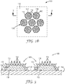
- FIG. 2 shows the pattern of clusters 106 in greater detail.
- the clusters 106 are arranged in a hexagonal array in which each cluster 106 has six equidistant neighbors (excluding edge effects).
- each individual cluster 106 is itself a hexagonal grouping of seven discrete abrasive features 108.
- each of the features 108 is generally circular in shape. However, other shapes such as squares, rectangles, lines and arcs, may also be used. In other embodiments, the features 108 are not clustered.
- the uncoated areas 110 provide open channels allowing swarf, dust, and other debris to be evacuated from the cutting areas where the features 108 contact the workpiece.
- FIG. 2b shows components of the features 108 in further detail and FIG. 3 shows two of the features 108 in cross-section.
- each feature 108 includes a layer of make resin 112 that is preferentially deposited onto the major surface 104 along an interface 118.
- the make resin 112 coats selective areas of the backing 102, thereby forming the base layer for each discrete feature 108, or "island", on the backing 102.
- a plurality of abrasive particles 114 contact the make resin 112 and generally extend in directions away from the major surface 104.
- the particles 114 are generally in registration with the make resin 112 when viewed in directions normal to the plane of the major surface 104.
- the particles 114 as a whole, generally extend across areas of the major surface 104 that are coated by the make resin 112, but do not generally extend across areas of the major surface 104 that are not coated by the make resin 112.
- the particles 114 are at least partially embedded in the make resin 112.
- a size resin 116 contacts both the make resin 112 and the particles 114 and extends on and around both the make resin 112 and the particles 114.
- the size resin 116 is generally in registration with both the make resin 112 and the particles 114 when viewed in directions normal to the plane of the major surface 104.
- the size resin 116 generally extends across areas of the major surface 104 coated by the make resin 112, but does not generally extend across areas of the major surface 104 not coated by the make resin 112.
- the size resin 116 contacts the make resin 112, the abrasive particles 114, and the backing 102.
- essentially all of the abrasive particles 114 are encapsulated by the combination of the make and size resins 112, 116.
- the particles 114 are described here as being “generally in registration” with the make resin 112, it is to be understood that the particles 114 themselves are discrete in nature and have small gaps located between them. Therefore, the particles 114 do not cover the entire area of the underlying make resin 112. Conversely, it is to be understood that while the size resin 116 is “in registration” with make resin 112 and the particles 114, size resin 116 can optionally extend over a slightly oversized area compared with that covered by the make resin 112 and particles 114, as shown in FIG. 2b . In the embodiment shown, the make resin 112 is fully encapsulated by the size resin 116, the particles 114, and the backing 102.
- all of the features 108 on the backing 102 need not be discrete.
- the make resin 112 associated with adjacent features 108 may be in such close proximity that the features 108 contact each other, or become interconnected.
- two or more features 108 may be interconnected with each other within a cluster 106, although the features 108 in separate clusters 106 are not interconnected.
- the backing 102 is uniform in thickness and generally flat.
- the interface 118 where the major surface 104 contacts the make resin 112 is generally coplanar with the areas of the major surface 104 that do not contact the make resin 112 (i.e. uncoated areas 110).
- a backing 102 with a generally uniform thickness is preferred to alleviate stiffness variations and improve conformability of the article 100 to the workpiece. This aspect is further advantageous because it evenly distributes the stress on the backing, which improves durability of the article 100 and extends its operational lifetime.
- the provided abrasive articles present a solution to particular problems with conventional coated abrasive sheets.
- One problem is that conventional abrasive sheets tend to curl in humid environments.
- Another problem is that these coated abrasive sheets often curl immediately when made, a phenomenon known as "intrinsic curl.”
- intrinsic curl To mitigate intrinsic curl, manufacturers can pre-flex these abrasive sheets, but this involves additional processing and still does not effectively address curl that is subsequently induced by the environment.
- the provided abrasive articles have abrasive particles extending across a plurality of islands, or discrete coated regions, along the major surface, while uncoated areas of the major surface are maintained between the islands. It was discovered that when areas of the major surface surrounding these islands do not contact any of the make resin, abrasive particles, or size resin, these abrasive articles display superior resistance to curling when immersed in water or subjected to humid environments.
- these abrasive articles have substantially reduced curl when manufactured and reduce the need for pre-flexing of the abrasive sheets after the make and size resins have been hardened.
- the abrasive articles When tested in accordance with the Dry Curl test (described in the Examples section below), the abrasive articles preferably display a curl radius of at least 20 centimeters, more preferably display a curl radius of at least 50 centimeters, and most preferably display a curl radius of at least 100 centimeters.
- the abrasive articles When tested in accordance with the Wet Curl test (described in the Examples section below), the abrasive articles preferably display a curl radius of at least 2 centimeters, more preferably display a curl radius of at least 5 centimeters, and most preferably display a curl radius of at least 7 centimeters.
- these abrasive articles have been found to display a high degree of flexibility, since a substantial portion of the backing is uncoated.
- the greater flexibility in turn enhances durability. This is particularly shown by its high resistance to tearing and delamination when the abrasive article is subjected to crumpling under wet and dry conditions.
- the abrasive article 100 described above uses a two-dimensional hexagonal coating pattern for the features 108. While the pattern is two-dimensional, the features 108 themselves have some thickness that results in a "feature height" perpendicular to the plane of the page. However, other coating patterns are also possible, with some offering particular advantages over others.
- the pattern includes a plurality of replicated polygonal clusters and/or features, including ones in the shape of triangles, squares, rhombuses, and the like.
- triangular clusters could be used where each cluster has three or more generally circular abrasive features. Since the abrasive features 108 increase the stiffness of the underlying backing 102 on a local level, the pattern of the abrasive article 100 may be tailored to have enhanced bending flexibility along preferred directions.
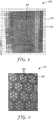
- FIG. 4 shows an abrasive article 200 according to an alternative embodiment displaying a pattern that includes a random array of features.
- the article 200 has a backing 202 with a major surface 204 and an array of discrete and generally circular abrasive features 208 that contact, and extend across, the major surface 204.
- the article 200 differs in that the features 208 are random.
- the features 208 may be semi-random, or have limited aspects that are ordered.
- random patterns are non-directional within the plane of the major surface of the backing, helping minimize variability in cut performance.
- a random pattern helps avoid creating systematic lines of weakness which may induce curling of the abrasive article along those directions.
- article 200 including the configuration of the abrasive features 208, are analogous to those of article 100 and shall not be repeated here.
- Like reference numerals refer to like elements described previously.
- the abrasive articles 100,200 preferably have an abrasive coverage (measured as a percentage of the major surface 104) that fits the desired application.
- abrasive coverage advantageously provides greater cutting area between the abrasive particles 114 and the workpiece.
- decreasing abrasive coverage increases the size of the uncoated areas 110. Increasing the size of the uncoated areas 110, in turn, can provide greater space to clear dust and debris and help prevent undesirable loading during an abrading operation.
- low levels of abrasive coverage were nonetheless found to provide very high levels of cut, despite the relatively small cutting area between abrasive and the workpiece.
- fine grade abrasives could be coated onto the backing 102 at less than 50 percent coverage while providing cut performance similar to that of a fully coated sheet.
- coarse grade abrasives could be coated onto the backing 102 at less than 20 percent coverage while providing cut performance similar to that of a fully coated sheet.
- the abrasive particles 114 have an average size (i.e. average particle diameter) ranging from 68 micrometers to 270 micrometers, while the make resin 112 has a coverage that is preferably at most 30 percent, more preferably at most 20 percent, and most preferably at most 10 percent. In other embodiments, the abrasive particles 114 have an average size ranging from 0.5 micrometers to 68 micrometers, while the make resin 112 has a coverage that is preferably at most 70 percent, more preferably at most 60 percent, and most preferably at most 50 percent.
- the backing 102 may be constructed from various materials known in the art for making coated abrasive articles, including sealed coated abrasive backings and porous non-sealed backings.
- the thickness of the backing generally ranges from about 0.02 to about 5 millimeters, more preferably from about 0.05 to about 2.5 millimeters, and most preferably from about 0.1 to about 0.4 millimeter, although thicknesses outside of these ranges may also be useful.
- the backing may be made of any number of various materials including those conventionally used as backings in the manufacture of coated abrasives.
- Exemplary flexible backings include polymeric film (including primed films) such as polyolefin film (e.g., polypropylene including biaxially oriented polypropylene, polyester film, polyamide film, cellulose ester film), metal foil, mesh, foam (e.g., natural sponge material or polyurethane foam), cloth (e.g., cloth made from fibers or yarns comprising polyester, nylon, silk, cotton, and/or rayon), scrim, paper, coated paper, vulcanized paper, vulcanized fiber, nonwoven materials, combinations thereof, and treated versions thereof.
- the backing may also be a laminate of two materials (e.g., paper/film, cloth/paper, film/cloth). Cloth backings may be woven or stitch bonded.
- the choice of backing material may depend, for example, on the intended application of the coated abrasive article.
- the thickness and smoothness of the backing should also be suitable to provide the desired thickness and smoothness of the coated abrasive article, wherein such characteristics of the coated abrasive article may vary depending, for example, on the intended application or use of the coated abrasive article.
- the backing may, optionally, have at least one of a saturant, a presize layer and/or a backsize layer.
- a saturant typically to seal the backing and/or to protect yarn or fibers in the backing. If the backing is a cloth material, at least one of these materials is typically used.
- the addition of the presize layer or backsize layer may additionally result in a 'smoother' surface on either the front and/or the back side of the backing.
- Other optional layers known in the art may also be used, as described in U.S. Patent No. 5,700,302 (Stoetzel et al. ).
- Suitable abrasive particles for the coated abrasive article 100 include any known abrasive particles or materials useable in abrasive articles.
- useful abrasive particles include fused aluminum oxide, heat treated aluminum oxide, white fused aluminum oxide, black silicon carbide, green silicon carbide, titanium diboride, boron carbide, tungsten carbide, titanium carbide, diamond, cubic boron nitride, garnet, fused alumina zirconia, sol gel abrasive particles, silica, iron oxide, chromia, ceria, zirconia, titania, silicates, metal carbonates (such as calcium carbonate (e.g., chalk, calcite, marl, travertine, marble and limestone), calcium magnesium carbonate, sodium carbonate, magnesium carbonate), silica (e.g., quartz, glass beads, glass bubbles and glass fibers) silicates (e.g., talc, clays, (montmorillonite) felds
- polymeric abrasive particles formed from a thermoplastic material e.g., polycarbonate, polyetherimide, polyester, polyethylene, polysulfone, polystyrene, acrylonitrile-butadiene-styrene block copolymer, polypropylene, acetal polymers, polyvinyl chloride, polyurethanes, nylon
- polymeric abrasive particles formed from crosslinked polymers e.g., phenolic resins, aminoplast resins, urethane resins, epoxy resins, melamine-formaldehyde, acrylate resins, acrylated isocyanurate resins, ureaformaldehyde resins, isocyanurate resins, acrylated urethane resins, acrylated epoxy resins
- a thermoplastic material e.g., polycarbonate, polyetherimide, polyester, polyethylene, polysulfone, polystyrene, acrylonitrile-butadiene-
- the abrasive particles typically have an average diameter of from about 0.1 to about 270 micrometers, and more desirably from about 1 to about 1300 micrometers. Coating weights for the abrasive particles may depend, for example, on the binder precursor used, the process for applying the abrasive particles, and the size of the abrasive particles, but typically range from about 5 to about 1350 grams per square meter.
- any of a wide selection of make and size resins 112, 116 known in the art may be used to secure the abrasive particles 114 to the backing 102.
- the resins 112, 116 typically include one or more binders having rheological and wetting properties suitable for selective deposition onto a backing.
- binders are formed by curing (e.g., by thermal means, or by using electromagnetic or particulate radiation) a binder precursor.
- first and second binder precursors are known in the abrasive art and include, for example, free-radically polymerizable monomer and/or oligomer, epoxy resins, acrylic resins, epoxy-acrylate oligomers, urethane-acrylate oligomers, urethane resins, phenolic resins, ureaformaldehyde resins, melamine-formaldehyde resins, aminoplast resins, cyanate resins, or combinations thereof.
- Useful binder precursors include thermally curable resins and radiation curable resins, which may be cured, for example, thermally and/or by exposure to radiation.
- Exemplary radiation cured crosslinked acrylate binders are described in issued U.S. Patent Nos. 4,751,138 (Tumey, et al. ) and 4,828,583 (Oxman, et al. ).
- one or more additional supersize resin layers are applied to the coated abrasive article 100. If a supersize resin is applied, it is preferably in registration with the make resin 112, particles 114, and size resin 116, as viewed in directions normal to the plane of the major surface of the backing.
- the supersize resin may include, for example, grinding aids and anti-loading materials.
- the supersize resin provides enhanced lubricity during an abrading operation.
- any of the make resin, size resin, and supersize resin described above optionally include one or more curatives.
- Curatives include those that are photosensitive or thermally sensitive, and preferably comprise at least one free-radical polymerization initiator and at least one cationic polymerization catalyst, which may be the same or different.
- the binder precursors employed in the present embodiment are preferably photosensitive, and more preferable comprise a photoinitiator and/or a photocatalyst.
- the photoinitiator is capable of at least partially polymerizing (e.g., curing) free-radically polymerizable components of the binder precursor.
- Useful photoinitiators include those known as useful for photocuring free-radically polyfunctional acrylates.
- Exemplary photoinitiators include bis (2,4,6-trimethylbenzoyl)-phenylphosphineoxide, commercially available under the trade designation "IRGACURE 819" from BASF Corporation, Florham Park, New Jersey; benzoin and its derivatives such as alpha-methylbenzoin; alpha-phenylbenzoin; alpha-allylbenzoin; alpha-benzylbenzoin; benzoin ethers such as benzil dimethyl ketal (e.g., as commercially available under the trade designation "IRGACURE 651” from BASF Corporation), benzoin methyl ether, benzoin ethyl ether, benzoin n-butyl ether; acetophenone and its derivative
- Photocatalysts as defined herein are materials that form active species that, if exposed to actinic radiation, are capable of at least partially polymerizing the binder precursor, e.g., an onium salt and/or cationic organometallic salt.
- onium salt photocatalysts comprise iodonium complex salts and/or sulfonium complex salts.
- Aromatic onium salts, useful in practice of the present embodiments, are typically photosensitive only in the ultraviolet region of the spectrum. However, they can be sensitized to the near ultraviolet and the visible range of the spectrum by sensitizers for known photolyzable organic halogen compounds.
- Photoinitiators and photocatalysts useful in the present invention can be present in an amount in the range of 0.01 to 10 weight percent, desirably 0.01 to 5, most desirably 0.1 to 2 weight percent, based on the total amount of photocurable (i.e., crosslinkable by electromagnetic radiation) components of the binder precursor, although amounts outside of these ranges may also be useful.
- the abrasive coatings described above optionally comprise one or more fillers.
- Fillers are typically organic or inorganic particulates dispersed within the resin and may, for example, modify either the binder precursor or the properties of the cured binder, or both, and/or may simply, for example, be used to reduce cost.
- the fillers may be present, for example, to block pores and passages within the backing, to reduce its porosity and provide a surface to which the maker coat will bond effectively.
- the addition of a filler at least up to a certain extent, typically increases the hardness and toughness of the cured binder.
- Inorganic particulate filler commonly has an average particle size ranging from about 1 micrometer to about 100 micrometers, more preferably from about 5 to about 50 micrometers, and sometimes even from about 10 to about 25 micrometers.
- the filler typically has a specific gravity in the range of 1.5 to 4.5, and an average particle size of the filler will preferably be less than the average particle size of the abrasive particles.
- useful fillers include: metal carbonates such as calcium carbonate (in the form of chalk, calcite, marl, travertine, marble or limestone), calcium magnesium carbonate, sodium carbonate, and magnesium carbonate; silicas such as quartz, glass beads, glass bubbles and glass fibers; silicates such as talc, clays, feldspar, mica, calcium silicate, calcium metasilicate, sodium aluminosilicate, sodium-potassium alumina silicate, and sodium silicate ; metal sulfates such as calcium sulfate, barium sulfate, sodium sulfate, aluminum sodium sulfate, and aluminum sulfate ; gypsum; vermiculite ; wood flour ; alumina trihydrate; carbon black ; metal oxides such as calcium oxide (lime), aluminum oxide, titanium dioxide, alumina hydrate, alumina monohydrate; and metal sulfites such as calcium sulfite.
- metal carbonates such as calcium carbonate (in the
- viscosity enhancers or thickeners include viscosity enhancers or thickeners. These additives may be added to a composition of the present embodiment as a cost savings measure or as a processing aid, and may be present in an amount that does not significantly adversely affect properties of a composition so formed. Increase in dispersion viscosity is generally a function of thickener concentration, degree of polymerization, chemical composition or a combination thereof.
- An example of a suitable commercially available thickener is available under the trade designation "CAB-O-SIL M-5" from Cabot Corporation, Boston, Massachusetts.
- anti-foaming agents include "FOAMSTAR S125" from Cognis Corporation, Cincinnati, Ohio.
- Useful process aids include acidic polyester dispersing agents which aid the dispersion of the abrasive particles throughout the polymerizable mixture, such as "BYK W-985" from Byk-Chemie, GmbH, Wesel, Germany.
- the make resin 112 is preferentially applied to the major surface 104 of the backing 102 in a plurality of discrete areas that provide a random or ordered array on the major surface 104 as illustrated, for example, in FIGS. 1 and 4 .
- abrasive particles 114 are applied to the discrete areas of the make resin 112, and the make resin 112 is hardened.
- a size resin is then preferentially applied over the abrasive particles 114 and the make resin 112 and in contact with backing 102 (but it is not applied to the open areas 110 on the backing 102).
- the size resin 116 is hardened to provide the abrasive article 100.
- the selective application of the make resin 112 and size resin 116 can be achieved using contact methods, non-contact methods, or some combination of both.
- Suitable contact methods include mounting a template, such as a stencil or woven screen, against the backing of the article to mask off areas that are not to be coated.
- Non-contact methods include inkjet-type printing and other technologies capable of selectively coating patterns onto the backing without need for a template.
- Stencil printing uses a frame to support a resin-blocking stencil.
- the stencil forms open areas allowing the transfer of resin to produce a sharply-defined image onto a substrate.
- a roller or squeegee is moved across the screen stencil, forcing or pumping the resin or slurry past the threads of the woven mesh in the open areas.
- Screen printing is also a stencil method of print making in which a design is imposed on a screen of silk or other fine mesh, with blank areas coated with an impermeable substance, and the resin or slurry is forced through the mesh onto the printing surface.
- printing of lower profile and higher fidelity features can be enabled by screen printing. Exemplary uses of screen printing are described in U.S. Patent No. 4,759,982 (Janssen et al. ).
- Yet another applicable contact method uses a combination of screen printing and stencil printing, where a woven mesh is used to support a stencil.
- the stencil includes open areas of mesh through which make resin/size resin can be deposited in the desired patter of discrete areas onto the backing.
- FIG. 5 shows a stencil 350 for preparing the patterned coated abrasive articles shown in FIGS. 1-3 .
- the stencil 350 includes a generally planar body 352 and a plurality of perforations 354 extending through the body 352.
- a frame 356 surrounds the body on four sides.
- the stencil 350 can be made from a polymer, metal, or ceramic material and is preferably thin. Combinations of metal and woven plastics are also available. These provide enhanced flexibility of the stencil.
- Metal stencils can be etched into a pattern.
- Other suitable stencil materials include polyester films that have a thickness ranging from 1 to 20 mils (0.076 to 0.51 millimeters), more preferably ranging from 3 to 7 mils (0.13 to 0.25 millimeters).
- FIG. 6 shows features of the stencil 350 in greater detail.
- the perforations 354 assume the hexagonal arrangement of clusters and features as described previously for article 100.
- the perforations are created in a precise manner by uploading a suitable digital image into a computer which automatically guides a laser to cut the perforations 354 into the stencil body 352.
- the stencil 350 can be advantageously used to provide precisely defined coating patterns.
- a layer of make resin 112 is selectively applied to the backing 102 by overlaying the stencil 350 on the backing 102 and applying the make resin 112 to the stencil 350.
- the make resin 112 is applied in a single pass using a squeegee, doctor blade, or other blade-like device.
- the stencil 350 is removed prior to hardening of the make resin 112. If so, the viscosity of the make resin 112 is preferably sufficiently high that there is minimal flow out that would distort the originally printed pattern.
- the mineral particles 114 can be deposited on the layer of make resin 112 using a powder coating process or electrostatic coating process.
- electrostatic coating the abrasive particles 114 are applied in an electric field, allowing the particles 114 to be advantageously aligned with their long axes normal to the major surface 104.
- the mineral particles 114 are coated over the entire coated backing 102 and the particles 114 preferentially bond to the areas coated with the tacky make resin 112. After the particles 114 have been preferentially coated onto the make resin 112, the make resin 112 is then partially or fully hardened.
- the hardening step occurs by subjecting the abrasive article 100 at elevated temperatures, exposure to actinic radiation, or a combination of both, to crosslink the make resin 112. Excess particles are then removed from the uncoated areas of the backing 102.
- the stencil 350 is again overlaid on the coated backing 102 and positioned with the perforations 354 in registration with the previously hardened make resin 112 and abrasive particles 114.
- the size resin 116 is preferentially applied to the hardened make resin 112 and abrasive particles 114 by applying the make resin 112 to the stencil 350.
- the size resin 116 has an initial viscosity allowing the size resin 116 to flow and encapsulate exposed areas of the abrasive particles 114 and the make resin 112 prior to hardening.
- the stencil 350 may or may not be detached following the application of the size resin 116.
- the size resin 116 is hardened to provide the completed abrasive article 100.
- the abrasive articles 100, 200 may include one or more additional features that further enhance ease of use, performance or durability.
- the articles optionally include a plurality of dust extraction holes that are connected to a source of vacuum to remove dust and debris from the major surface of the abrasive articles.
- the backing 102, 202 may include a fibrous material, such as a scrim or non-woven material, facing the opposing direction from the major surface 104, 204.
- the fibrous material can facilitate coupling the article 100, 200 to a power tool.
- the backing 102, 202 includes one-half of a hook and loop attachment system, the other half being disposed on a plate affixed to the power tool.
- a pressure sensitive adhesive may be used for this purpose.
- Such an attachment system secures the article 100, 200 to the power tool while allowing convenient replacement of the article 100, 200 between abrading operations.
- a 4.5 by 5.5 inch (11.4 by 14.0 cm) sample sheet was conditioned at 90°F (32.2°C) and 90% relative humidity for 4 hours, after which the 5.5 inch (14.0 cm) edge was centered perpendicularly on an aluminum plate having a series of arcs marked thereon.
- the amount of curl reported corresponds to the radius of the arc traced by the curled sample sheet, that is, the larger the number, the flatter the sample.
- Coated abrasives were laminated to a dual sided adhesive film, and die cut into 4-inch (10.2 cm) diameter discs.
- the laminated coated abrasive was secured to the driven plate of a Schiefer Abrasion Tester, obtained from Frazier Precision Co., Gaithersburg, Maryland, which had been plumbed for wet testing.
- Disc shaped acrylic plastic workpieces, 4-inch (10.2 cm) outside diameter by 1.27 cm thick, available under the trade designation "POLYCAST" were obtained from Seelye Plastics, Bloomington, Minnesota.
- POLYCAST trade designation
- a 10 pound (4.54 kg) weight was placed on the abrasion tester weight platform and the mounted abrasive specimen lowered onto the workpiece and the machine turned on.
- the machine was set to run for 500 cycles and then automatically stop. After each 500 cycles of the test, the workpiece was rinsed with water, dried and weighed.
- the cumulative cut for each 500-cycle test was the difference between the initial weight and the weight following each test, and is reported as the average value of 4 measurements.
- Rz is the average vertical distance between the highest and lowest point of a test area.
- Ra the average scratch depth, is the distance between average height and the mean distance between the highest and lowest point in the test area. Both Rz and Ra were measured four times on three test areas of each sample from the sanding tests using a profilometer, available under the trade designation "SURTRONIC 25 PROFILOMETER” from Taylor Hobson, Inc., Sheffield, England.
- 1,264.0 grams BB077 was weighed into a 64 oz. (1.89 liter) plastic container.
- a premix solution containing 148.0 grams of a 34% aqueous urea solution, 1.1 grams IW-33 and 0.54 grams FS-125, was dispersed for 10 minutes at 70°F (21.1°C) in the resin using a high speed mixer, model number "SERIES 2000 MODEL 84" from Premier Mill Corporation, Reading, Pennsylvania. 400.0 grams Q-325 was then added, followed by 25.0 grams CM-5, and mixing continued until homogeneously dispersed (approximately 20 minutes).
- EPON-828 400.0 grams EPON-828, 300.0 grams UVR-6110, and 300.0 grams SR-351 were charged into a 16 oz. (0.47 liter) black plastic container and dispersed in the resin for 5 minutes at 70°F (21.1°C) using the high speed mixer. To that mixture 30.0 grams CPI-6976 and 10.0 grams D-1173 were added and dispersed until homogeneous (approximately 10 minutes).
- a stencil was used with a screen printer to provide the desired pattern.
- the stencil was taped into the screen frame of a screen printer, model number "AT-1200H/E” from ATMA Champ Ent. Corp., Taipei, Taiwan.
- a 12 inch by 20 inch (30.48 by 50.8 cm) sheet of CWT paper was taped to the printer backing plate, and the plate secured in registration within the screen printer.
- Approximately 75 grams of the phenolic make coat was spread over the stencil at 70°F (21.1°C) using a urethane squeegee, then stencil printed onto the paper backing.
- the backing plate and coated paper assembly was immediately removed from the screen printer.
- Mineral GC-80 was electrostatically applied to the phenolic make resin using a powder coater, type "EASY 01-F/02-F" from ITW Gema, St.
- Example 2 The general procedure as described in Example 1 was repeated, wherein the GC-80 abrasive mineral was substituted with F150X.
- the stencil was taped into the frame of small screen printer, obtained from APR Novastar, LLC, Huntington Valley, Pennsylvania.
- a 12 inch by 20 inch (30.48 by 50.8 cm) sheet of CWT paper was taped to a metal plate that was placed onto the printer backing plate, and the plate secured in registration within the screen printer.
- Approximately 35 grams of the acrylate make coat was spread over the stencil at 70°F (21.1°C) using a urethane squeegee, then stencil printed onto the paper backing.
- the backing plate and coated paper assembly was immediately removed from the screen printer.
- Mineral GC-80 was electrostatically applied to the acrylate make resin using the powder coater, and cured by passing twice through a UV processor, available from American Ultraviolet Company, Murray Hill, New Jersey, using two D-bulbs in sequence operating at 400 W/inch (157.5 W/cm) and a web speed of 40 ft/min (12.19 m/min), and allowed to cool. Meanwhile, the stencil was cleaned using ethanol soaked paper towels. Excess mineral was removed by lightly brushing the coated surface and the assembly again secured within the screen printer in registration with the stencil.
- the acrylate size coat was applied in registration over the abrasive mineral per the same method as used to apply the acrylate make coat, and the assembly cured by passing once through the UV processor at 400 W/inch (157.5 W/cm) and a web speed of 40 ft/min (12.19 m/min), followed by thermally curing for 5 minutes at 284°F (140°C). After curing the assembly was allowed to cool and the abrasive coated paper removed from the backing plate.
- Example 2 The general procedure as described in Example 1 was repeated for applying and curing the phenolic make coat and mineral. Rather than stencil coating in registration, the phenolic size coat was instead applied over the entire 12 by 20 inch (30.48 by 50.8 cm) sheet of make and mineral coated CWT paper using a 12-inch (25.4 cm) roll coater, obtained from Eagle Tool Company, Minneapolis, Minnesota, at a nip pressure of 50 psi (344.7 kPa), at 70°F (21.1°C). The assembly was then oven cured for 40 minutes at 240°F (115.6°C), after which it was allowed to cool and the coated paper removed from the backing plate.
- Example 3 The general procedure as described in Example 3 was repeated for applying and curing the acrylate make coat and mineral. Rather than stencil coating in registration, the acrylate size coat was instead applied over the entire 12 by 20 inch (30.48 by 50.8 cm) sheet of make and mineral coated CWT paper using the roll, at a nip pressure of 50 psi (344.7 kPa), at 70°F (21.1°C). The assembly was then cured by passing once through the UV processor at 400 W/inch (157.5 W/cm) and a web speed of 40 ft/min (12.19 m/min), followed by thermally curing for 5 minutes at 284°F (140°C). After curing the assembly was allowed to cool and the abrasive coated paper removed from the backing plate.
Description
- Coated abrasive articles are provided along with methods of making the same. More particularly, coated abrasive articles with patterned coatings are provided, along with methods of making the same.
- Coated abrasive articles are commonly used for abrading, grinding and polishing operations in both commercial and industrial applications. These operations are conducted on a wide variety of substrates, including wood, wood-like materials, plastics, fiberglass, soft metals, enamel surfaces, and painted surfaces. Some coated abrasives can be used in either wet or dry environments. In wet environments, common applications include filler sanding, putty sanding, primer sanding and paint finishing.
- In general, these abrasive articles include a paper or polymeric backing on which abrasive particles are adhered. The abrasive particles may be adhered using one or more tough and resilient binders to secure the particles to the backing during an abrading operation. In a manufacturing process, these binders are often processed in a flowable state to coat the backing and the particles, and then subsequently hardened to lock in a desired structure and provide the finished abrasive product.
- In a common construction, the backing has a major surface that is first coated with a "make" layer. Abrasive particles are then deposited onto the make layer such that the particles are at least partially embedded in the make layer. The make layer is then hardened (e.g., crosslinked) to secure the particles. Then, a second layer called a "size" layer is coated over the make layer and abrasive particles and also hardened. The size layer further stabilizes the particles and also enhances the strength and durability of the abrasive article. Optionally, additional layers may be added to modify the properties of the coated abrasive article.
A specific article for polishing stone is described inUS 5,551,960 . - A coated abrasive article can be evaluated based on certain performance properties. First, such an article should have a desirable balance between cut and finish-that is, an acceptable efficiency in removing material from the workpiece, along with an acceptable smoothness of the finished surface. Second, an abrasive article should also avoid excessive "loading", or clogging, which occurs when debris or swarf become trapped between the abrasive particles and hinder the cutting ability of the coated abrasive. Third, the abrasive article should be both flexible and durable to provide for longevity in use.
- Wet abrasive applications can provide unique challenges. Abrasive sheets may be soaked in water for extended periods of time, sometimes for more than 24 hours. A particular problem encountered with commercial coated abrasive articles in wet environments is the tendency for these coated articles to curl. Curling of the abrasive article can be a significant nuisance to the user. A similar effect can also occur when abrasive articles are stored in humid environments. To mitigate curling, abrasive sheets are sometimes pre-flexed in the manufacturing process, but this is generally ineffective in preventing curling during use.
- The present disclosure provides coated abrasive articles in which the make layer, abrasive particle layer, and size layer are coated onto a backing according to a coating pattern. All three components are substantially in registration with each other according to this pattern, thereby providing pervasive uncoated areas extending across the backing. Advantageously, this configuration provides a coated abrasive that displays superior curl-resistance compared with conventional abrasive articles. Moreover, this configuration resists loading, resists de-lamination, has enhanced flexibility, and decreases the quantity of raw materials required to achieve the same level of performance as conventional adhesive articles.
- In one aspect, there is provided an abrasive article according to claim 1. In another aspect, there is provided a method of making an abrasive article according to claim 7.
-
-
FIG. 1 is a plan view of an abrasive article according to one embodiment; -
FIG. 2a is an enlarged view of a portion of the abrasive article inFIG. 1 ; -
FIG. 2b is a further enlarged view of a sub-portion of the abrasive article inFIGS. 1 and 2a ; -
FIG. 3 is a cross-sectional view of the sub-portion of the abrasive article shown inFIGS. 1, 2a , and2b ; -
FIG. 4 is a plan view of an abrasive article according to another embodiment; -
FIG. 5 is a plan view of a template providing the pattern for the features of the article inFIGS. 1-3 ; and -
FIG. 6 is an enlarged fragmentary view of the template inFIG. 5 , showing features of the template in greater detail. - As used herein:
- "Feature" refers to an image that is defined by a selective coating process;
- "Coverage" refers to the percentage of surface area of the backing eclipsed by the features over the area subjected to the selective coating process;
- "Particle diameter" refers to the longest dimension of the particle; and
- "Cluster" refers to a group of features located in proximity to each other.
- An abrasive article according to one exemplary embodiment is shown in
FIG. 1 and is designated by thenumeral 100. As shown, theabrasive article 100 includes abacking 102 having a planarmajor surface 104 approximately parallel to the plane of the page. A plurality ofdiscrete clusters 106 are located on themajor surface 104 and arranged in a pre-determined pattern. In this embodiment, the pattern is a two-dimensional ordered array. Theabrasive article 100 occupies a planar rectangular region corresponding to the patterned region shown inFIG. 1 . -
FIG. 2 shows the pattern ofclusters 106 in greater detail. As shown in the figure, theclusters 106 are arranged in a hexagonal array in which eachcluster 106 has six equidistant neighbors (excluding edge effects). Further, eachindividual cluster 106 is itself a hexagonal grouping of seven discreteabrasive features 108. As shown, each of thefeatures 108 is generally circular in shape. However, other shapes such as squares, rectangles, lines and arcs, may also be used. In other embodiments, thefeatures 108 are not clustered. - Notably, there are
uncoated areas 110 of themajor surface 104 surrounding eachcluster 106 and located between neighboringclusters 106. Advantageously, during an abrading operation, theuncoated areas 110 provide open channels allowing swarf, dust, and other debris to be evacuated from the cutting areas where thefeatures 108 contact the workpiece. -
FIG. 2b shows components of thefeatures 108 in further detail andFIG. 3 shows two of thefeatures 108 in cross-section. As shown in these figures, eachfeature 108 includes a layer ofmake resin 112 that is preferentially deposited onto themajor surface 104 along aninterface 118. Themake resin 112 coats selective areas of thebacking 102, thereby forming the base layer for eachdiscrete feature 108, or "island", on thebacking 102. - A plurality of
abrasive particles 114 contact themake resin 112 and generally extend in directions away from themajor surface 104. Theparticles 114 are generally in registration with themake resin 112 when viewed in directions normal to the plane of themajor surface 104. In other words, theparticles 114, as a whole, generally extend across areas of themajor surface 104 that are coated by themake resin 112, but do not generally extend across areas of themajor surface 104 that are not coated by themake resin 112. Optionally, theparticles 114 are at least partially embedded in themake resin 112. - As further shown in
FIG. 3 , asize resin 116 contacts both themake resin 112 and theparticles 114 and extends on and around both themake resin 112 and theparticles 114. Thesize resin 116 is generally in registration with both themake resin 112 and theparticles 114 when viewed in directions normal to the plane of themajor surface 104. Like theabrasive particles 114, thesize resin 116 generally extends across areas of themajor surface 104 coated by themake resin 112, but does not generally extend across areas of themajor surface 104 not coated by themake resin 112. - Optionally and as shown, the
size resin 116 contacts themake resin 112, theabrasive particles 114, and thebacking 102. As another option, essentially all of theabrasive particles 114 are encapsulated by the combination of the make andsize resins - While the
particles 114 are described here as being "generally in registration" with themake resin 112, it is to be understood that theparticles 114 themselves are discrete in nature and have small gaps located between them. Therefore, theparticles 114 do not cover the entire area of theunderlying make resin 112. Conversely, it is to be understood that while thesize resin 116 is "in registration" withmake resin 112 and theparticles 114,size resin 116 can optionally extend over a slightly oversized area compared with that covered by themake resin 112 andparticles 114, as shown inFIG. 2b . In the embodiment shown, themake resin 112 is fully encapsulated by thesize resin 116, theparticles 114, and thebacking 102. - Further, all of the
features 108 on thebacking 102 need not be discrete. For example, themake resin 112 associated withadjacent features 108 may be in such close proximity that thefeatures 108 contact each other, or become interconnected. In some embodiments, two ormore features 108 may be interconnected with each other within acluster 106, although thefeatures 108 inseparate clusters 106 are not interconnected. - Preferably and as shown, the
backing 102 is uniform in thickness and generally flat. As a result, theinterface 118 where themajor surface 104 contacts themake resin 112 is generally coplanar with the areas of themajor surface 104 that do not contact the make resin 112 (i.e. uncoated areas 110). A backing 102 with a generally uniform thickness is preferred to alleviate stiffness variations and improve conformability of thearticle 100 to the workpiece. This aspect is further advantageous because it evenly distributes the stress on the backing, which improves durability of thearticle 100 and extends its operational lifetime. - The provided abrasive articles present a solution to particular problems with conventional coated abrasive sheets. One problem is that conventional abrasive sheets tend to curl in humid environments. Another problem is that these coated abrasive sheets often curl immediately when made, a phenomenon known as "intrinsic curl." To mitigate intrinsic curl, manufacturers can pre-flex these abrasive sheets, but this involves additional processing and still does not effectively address curl that is subsequently induced by the environment.
- Unlike conventional abrasive articles, the provided abrasive articles have abrasive particles extending across a plurality of islands, or discrete coated regions, along the major surface, while uncoated areas of the major surface are maintained between the islands. It was discovered that when areas of the major surface surrounding these islands do not contact any of the make resin, abrasive particles, or size resin, these abrasive articles display superior resistance to curling when immersed in water or subjected to humid environments.
- Additionally, these abrasive articles have substantially reduced curl when manufactured and reduce the need for pre-flexing of the abrasive sheets after the make and size resins have been hardened. When tested in accordance with the Dry Curl test (described in the Examples section below), the abrasive articles preferably display a curl radius of at least 20 centimeters, more preferably display a curl radius of at least 50 centimeters, and most preferably display a curl radius of at least 100 centimeters. When tested in accordance with the Wet Curl test (described in the Examples section below), the abrasive articles preferably display a curl radius of at least 2 centimeters, more preferably display a curl radius of at least 5 centimeters, and most preferably display a curl radius of at least 7 centimeters.
- As a further advantage, these abrasive articles have been found to display a high degree of flexibility, since a substantial portion of the backing is uncoated. The greater flexibility in turn enhances durability. This is particularly shown by its high resistance to tearing and delamination when the abrasive article is subjected to crumpling under wet and dry conditions.
- The
abrasive article 100 described above uses a two-dimensional hexagonal coating pattern for thefeatures 108. While the pattern is two-dimensional, thefeatures 108 themselves have some thickness that results in a "feature height" perpendicular to the plane of the page. However, other coating patterns are also possible, with some offering particular advantages over others. - In some embodiments, the pattern includes a plurality of replicated polygonal clusters and/or features, including ones in the shape of triangles, squares, rhombuses, and the like. For example, triangular clusters could be used where each cluster has three or more generally circular abrasive features. Since the
abrasive features 108 increase the stiffness of theunderlying backing 102 on a local level, the pattern of theabrasive article 100 may be tailored to have enhanced bending flexibility along preferred directions. - The coating pattern need not be ordered. For example,
FIG. 4 shows anabrasive article 200 according to an alternative embodiment displaying a pattern that includes a random array of features. Like thearticle 100, thearticle 200 has abacking 202 with amajor surface 204 and an array of discrete and generally circularabrasive features 208 that contact, and extend across, themajor surface 204. However, thearticle 200 differs in that thefeatures 208 are random. Optionally, thefeatures 208 may be semi-random, or have limited aspects that are ordered. Advantageously, random patterns are non-directional within the plane of the major surface of the backing, helping minimize variability in cut performance. As a further advantage, a random pattern helps avoid creating systematic lines of weakness which may induce curling of the abrasive article along those directions. - Other aspects of
article 200, including the configuration of theabrasive features 208, are analogous to those ofarticle 100 and shall not be repeated here. Like reference numerals refer to like elements described previously. - The abrasive articles 100,200 preferably have an abrasive coverage (measured as a percentage of the major surface 104) that fits the desired application. On one hand, increasing abrasive coverage advantageously provides greater cutting area between the
abrasive particles 114 and the workpiece. On the other hand, decreasing abrasive coverage increases the size of theuncoated areas 110. Increasing the size of theuncoated areas 110, in turn, can provide greater space to clear dust and debris and help prevent undesirable loading during an abrading operation. - Advantageously, low levels of abrasive coverage were nonetheless found to provide very high levels of cut, despite the relatively small cutting area between abrasive and the workpiece. In particular, it was found that fine grade abrasives could be coated onto the
backing 102 at less than 50 percent coverage while providing cut performance similar to that of a fully coated sheet. Similarly, it was found that coarse grade abrasives could be coated onto thebacking 102 at less than 20 percent coverage while providing cut performance similar to that of a fully coated sheet. - In some embodiments, the
abrasive particles 114 have an average size (i.e. average particle diameter) ranging from 68 micrometers to 270 micrometers, while themake resin 112 has a coverage that is preferably at most 30 percent, more preferably at most 20 percent, and most preferably at most 10 percent. In other embodiments, theabrasive particles 114 have an average size ranging from 0.5 micrometers to 68 micrometers, while themake resin 112 has a coverage that is preferably at most 70 percent, more preferably at most 60 percent, and most preferably at most 50 percent. - The
backing 102 may be constructed from various materials known in the art for making coated abrasive articles, including sealed coated abrasive backings and porous non-sealed backings. Preferably, the thickness of the backing generally ranges from about 0.02 to about 5 millimeters, more preferably from about 0.05 to about 2.5 millimeters, and most preferably from about 0.1 to about 0.4 millimeter, although thicknesses outside of these ranges may also be useful. - The backing may be made of any number of various materials including those conventionally used as backings in the manufacture of coated abrasives. Exemplary flexible backings include polymeric film (including primed films) such as polyolefin film (e.g., polypropylene including biaxially oriented polypropylene, polyester film, polyamide film, cellulose ester film), metal foil, mesh, foam (e.g., natural sponge material or polyurethane foam), cloth (e.g., cloth made from fibers or yarns comprising polyester, nylon, silk, cotton, and/or rayon), scrim, paper, coated paper, vulcanized paper, vulcanized fiber, nonwoven materials, combinations thereof, and treated versions thereof. The backing may also be a laminate of two materials (e.g., paper/film, cloth/paper, film/cloth). Cloth backings may be woven or stitch bonded.
- The choice of backing material may depend, for example, on the intended application of the coated abrasive article. The thickness and smoothness of the backing should also be suitable to provide the desired thickness and smoothness of the coated abrasive article, wherein such characteristics of the coated abrasive article may vary depending, for example, on the intended application or use of the coated abrasive article.
- The backing may, optionally, have at least one of a saturant, a presize layer and/or a backsize layer. The purpose of these materials is typically to seal the backing and/or to protect yarn or fibers in the backing. If the backing is a cloth material, at least one of these materials is typically used. The addition of the presize layer or backsize layer may additionally result in a 'smoother' surface on either the front and/or the back side of the backing. Other optional layers known in the art may also be used, as described in
U.S. Patent No. 5,700,302 (Stoetzel et al. ). - Suitable abrasive particles for the coated
abrasive article 100 include any known abrasive particles or materials useable in abrasive articles. For example, useful abrasive particles include fused aluminum oxide, heat treated aluminum oxide, white fused aluminum oxide, black silicon carbide, green silicon carbide, titanium diboride, boron carbide, tungsten carbide, titanium carbide, diamond, cubic boron nitride, garnet, fused alumina zirconia, sol gel abrasive particles, silica, iron oxide, chromia, ceria, zirconia, titania, silicates, metal carbonates (such as calcium carbonate (e.g., chalk, calcite, marl, travertine, marble and limestone), calcium magnesium carbonate, sodium carbonate, magnesium carbonate), silica (e.g., quartz, glass beads, glass bubbles and glass fibers) silicates (e.g., talc, clays, (montmorillonite) feldspar, mica, calcium silicate, calcium metasilicate, sodium aluminosilicate, sodium silicate) metal sulfates (e.g., calcium sulfate, barium sulfate, sodium sulfate, aluminum sodium sulfate, aluminum sulfate), gypsum, aluminum trihydrate, graphite, metal oxides (e.g., tin oxide, calcium oxide), aluminum oxide, titanium dioxide) and metal sulfites (e.g., calcium sulfite), and metal particles (e.g., tin, lead, copper). - It is also possible to use polymeric abrasive particles formed from a thermoplastic material (e.g., polycarbonate, polyetherimide, polyester, polyethylene, polysulfone, polystyrene, acrylonitrile-butadiene-styrene block copolymer, polypropylene, acetal polymers, polyvinyl chloride, polyurethanes, nylon), polymeric abrasive particles formed from crosslinked polymers (e.g., phenolic resins, aminoplast resins, urethane resins, epoxy resins, melamine-formaldehyde, acrylate resins, acrylated isocyanurate resins, ureaformaldehyde resins, isocyanurate resins, acrylated urethane resins, acrylated epoxy resins), and combinations thereof.
- Other exemplary abrasive particles are described, for example, in
U.S. Patent No. 5,549,962 (Holmes et al. ). - The abrasive particles typically have an average diameter of from about 0.1 to about 270 micrometers, and more desirably from about 1 to about 1300 micrometers. Coating weights for the abrasive particles may depend, for example, on the binder precursor used, the process for applying the abrasive particles, and the size of the abrasive particles, but typically range from about 5 to about 1350 grams per square meter.
- Any of a wide selection of make and
size resins abrasive particles 114 to thebacking 102. Theresins - Typically, binders are formed by curing (e.g., by thermal means, or by using electromagnetic or particulate radiation) a binder precursor. Useful first and second binder precursors are known in the abrasive art and include, for example, free-radically polymerizable monomer and/or oligomer, epoxy resins, acrylic resins, epoxy-acrylate oligomers, urethane-acrylate oligomers, urethane resins, phenolic resins, ureaformaldehyde resins, melamine-formaldehyde resins, aminoplast resins, cyanate resins, or combinations thereof. Useful binder precursors include thermally curable resins and radiation curable resins, which may be cured, for example, thermally and/or by exposure to radiation.
- Exemplary radiation cured crosslinked acrylate binders are described in issued
U.S. Patent Nos. 4,751,138 (Tumey, et al. ) and4,828,583 (Oxman, et al. ). - Optionally, one or more additional supersize resin layers are applied to the coated
abrasive article 100. If a supersize resin is applied, it is preferably in registration with themake resin 112,particles 114, andsize resin 116, as viewed in directions normal to the plane of the major surface of the backing. The supersize resin may include, for example, grinding aids and anti-loading materials. In some embodiments, the supersize resin provides enhanced lubricity during an abrading operation. - Any of the make resin, size resin, and supersize resin described above optionally include one or more curatives. Curatives include those that are photosensitive or thermally sensitive, and preferably comprise at least one free-radical polymerization initiator and at least one cationic polymerization catalyst, which may be the same or different. In order to minimize heating during cure, while preserving pot-life of the binder precursor, the binder precursors employed in the present embodiment are preferably photosensitive, and more preferable comprise a photoinitiator and/or a photocatalyst.
- The photoinitiator is capable of at least partially polymerizing (e.g., curing) free-radically polymerizable components of the binder precursor. Useful photoinitiators include those known as useful for photocuring free-radically polyfunctional acrylates. Exemplary photoinitiators include bis (2,4,6-trimethylbenzoyl)-phenylphosphineoxide, commercially available under the trade designation "IRGACURE 819" from BASF Corporation, Florham Park, New Jersey; benzoin and its derivatives such as alpha-methylbenzoin; alpha-phenylbenzoin; alpha-allylbenzoin; alpha-benzylbenzoin; benzoin ethers such as benzil dimethyl ketal (e.g., as commercially available under the trade designation "IRGACURE 651" from BASF Corporation), benzoin methyl ether, benzoin ethyl ether, benzoin n-butyl ether; acetophenone and its derivatives such as 2-hydroxy-2-methyl-1-phenyl-1-propanone (e.g., as commercially available under the trade designation "DAROCUR 1173" from BASF Corporation. Photocatalysts as defined herein are materials that form active species that, if exposed to actinic radiation, are capable of at least partially polymerizing the binder precursor, e.g., an onium salt and/or cationic organometallic salt. Preferably, onium salt photocatalysts comprise iodonium complex salts and/or sulfonium complex salts. Aromatic onium salts, useful in practice of the present embodiments, are typically photosensitive only in the ultraviolet region of the spectrum. However, they can be sensitized to the near ultraviolet and the visible range of the spectrum by sensitizers for known photolyzable organic halogen compounds. Useful commercially available photocatalysts include an aromatic sulfonium complex salt having the trade designation "UVI-6976", available from Dow Chemical Co. Photoinitiators and photocatalysts useful in the present invention can be present in an amount in the range of 0.01 to 10 weight percent, desirably 0.01 to 5, most desirably 0.1 to 2 weight percent, based on the total amount of photocurable (i.e., crosslinkable by electromagnetic radiation) components of the binder precursor, although amounts outside of these ranges may also be useful.
- The abrasive coatings described above optionally comprise one or more fillers. Fillers are typically organic or inorganic particulates dispersed within the resin and may, for example, modify either the binder precursor or the properties of the cured binder, or both, and/or may simply, for example, be used to reduce cost. In coated abrasives, the fillers may be present, for example, to block pores and passages within the backing, to reduce its porosity and provide a surface to which the maker coat will bond effectively. The addition of a filler, at least up to a certain extent, typically increases the hardness and toughness of the cured binder. Inorganic particulate filler commonly has an average particle size ranging from about 1 micrometer to about 100 micrometers, more preferably from about 5 to about 50 micrometers, and sometimes even from about 10 to about 25 micrometers. Depending on the ultimate use of the abrasive article, the filler typically has a specific gravity in the range of 1.5 to 4.5, and an average particle size of the filler will preferably be less than the average particle size of the abrasive particles. Examples of useful fillers include: metal carbonates such as calcium carbonate (in the form of chalk, calcite, marl, travertine, marble or limestone), calcium magnesium carbonate, sodium carbonate, and magnesium carbonate; silicas such as quartz, glass beads, glass bubbles and glass fibers; silicates such as talc, clays, feldspar, mica, calcium silicate, calcium metasilicate, sodium aluminosilicate, sodium-potassium alumina silicate, and sodium silicate ; metal sulfates such as calcium sulfate, barium sulfate, sodium sulfate, aluminum sodium sulfate, and aluminum sulfate ; gypsum; vermiculite ; wood flour ; alumina trihydrate; carbon black ; metal oxides such as calcium oxide (lime), aluminum oxide, titanium dioxide, alumina hydrate, alumina monohydrate; and metal sulfites such as calcium sulfite.
- Other useful optional additives in the present embodiment include viscosity enhancers or thickeners. These additives may be added to a composition of the present embodiment as a cost savings measure or as a processing aid, and may be present in an amount that does not significantly adversely affect properties of a composition so formed. Increase in dispersion viscosity is generally a function of thickener concentration, degree of polymerization, chemical composition or a combination thereof. An example of a suitable commercially available thickener is available under the trade designation "CAB-O-SIL M-5" from Cabot Corporation, Boston, Massachusetts.
- Other useful optional additives in the present embodiment include anti-foaming agents, lubricants, plasticizers, grinding aids, diluents, coloring agents and process aids. Useful anti-foaming agents include "FOAMSTAR S125" from Cognis Corporation, Cincinnati, Ohio. Useful process aids include acidic polyester dispersing agents which aid the dispersion of the abrasive particles throughout the polymerizable mixture, such as "BYK W-985" from Byk-Chemie, GmbH, Wesel, Germany.
- In one exemplary method of making the
article 100, themake resin 112 is preferentially applied to themajor surface 104 of thebacking 102 in a plurality of discrete areas that provide a random or ordered array on themajor surface 104 as illustrated, for example, inFIGS. 1 and4 . Next,abrasive particles 114 are applied to the discrete areas of themake resin 112, and themake resin 112 is hardened. A size resin is then preferentially applied over theabrasive particles 114 and themake resin 112 and in contact with backing 102 (but it is not applied to theopen areas 110 on the backing 102). Finally, thesize resin 116 is hardened to provide theabrasive article 100. - In more detail, the selective application of the
make resin 112 andsize resin 116 can be achieved using contact methods, non-contact methods, or some combination of both. Suitable contact methods include mounting a template, such as a stencil or woven screen, against the backing of the article to mask off areas that are not to be coated. Non-contact methods include inkjet-type printing and other technologies capable of selectively coating patterns onto the backing without need for a template. - One applicable contact method is stencil printing. Stencil printing uses a frame to support a resin-blocking stencil. The stencil forms open areas allowing the transfer of resin to produce a sharply-defined image onto a substrate. A roller or squeegee is moved across the screen stencil, forcing or pumping the resin or slurry past the threads of the woven mesh in the open areas.
- Screen printing is also a stencil method of print making in which a design is imposed on a screen of silk or other fine mesh, with blank areas coated with an impermeable substance, and the resin or slurry is forced through the mesh onto the printing surface. Advantageously, printing of lower profile and higher fidelity features can be enabled by screen printing. Exemplary uses of screen printing are described in
U.S. Patent No. 4,759,982 (Janssen et al. ). - Yet another applicable contact method uses a combination of screen printing and stencil printing, where a woven mesh is used to support a stencil. The stencil includes open areas of mesh through which make resin/size resin can be deposited in the desired patter of discrete areas onto the backing.
-
FIG. 5 shows astencil 350 for preparing the patterned coated abrasive articles shown inFIGS. 1-3 . As shown, thestencil 350 includes a generallyplanar body 352 and a plurality ofperforations 354 extending through thebody 352. Optionally and as shown, aframe 356 surrounds the body on four sides. Thestencil 350 can be made from a polymer, metal, or ceramic material and is preferably thin. Combinations of metal and woven plastics are also available. These provide enhanced flexibility of the stencil. Metal stencils can be etched into a pattern. Other suitable stencil materials include polyester films that have a thickness ranging from 1 to 20 mils (0.076 to 0.51 millimeters), more preferably ranging from 3 to 7 mils (0.13 to 0.25 millimeters). -
FIG. 6 shows features of thestencil 350 in greater detail. As indicated in the figure, theperforations 354 assume the hexagonal arrangement of clusters and features as described previously forarticle 100. In some embodiments, the perforations are created in a precise manner by uploading a suitable digital image into a computer which automatically guides a laser to cut theperforations 354 into thestencil body 352. - The
stencil 350 can be advantageously used to provide precisely defined coating patterns. In one embodiment, a layer ofmake resin 112 is selectively applied to thebacking 102 by overlaying thestencil 350 on thebacking 102 and applying themake resin 112 to thestencil 350. In some embodiments, themake resin 112 is applied in a single pass using a squeegee, doctor blade, or other blade-like device. Optionally, thestencil 350 is removed prior to hardening of themake resin 112. If so, the viscosity of themake resin 112 is preferably sufficiently high that there is minimal flow out that would distort the originally printed pattern. - The
mineral particles 114 can be deposited on the layer ofmake resin 112 using a powder coating process or electrostatic coating process. In electrostatic coating, theabrasive particles 114 are applied in an electric field, allowing theparticles 114 to be advantageously aligned with their long axes normal to themajor surface 104. In some embodiments, themineral particles 114 are coated over the entirecoated backing 102 and theparticles 114 preferentially bond to the areas coated with thetacky make resin 112. After theparticles 114 have been preferentially coated onto themake resin 112, themake resin 112 is then partially or fully hardened. In some embodiments, the hardening step occurs by subjecting theabrasive article 100 at elevated temperatures, exposure to actinic radiation, or a combination of both, to crosslink themake resin 112. Excess particles are then removed from the uncoated areas of thebacking 102. - In an exemplary final coating step, the
stencil 350 is again overlaid on thecoated backing 102 and positioned with theperforations 354 in registration with the previously hardenedmake resin 112 andabrasive particles 114. Then, thesize resin 116 is preferentially applied to thehardened make resin 112 andabrasive particles 114 by applying themake resin 112 to thestencil 350. Preferably, thesize resin 116 has an initial viscosity allowing thesize resin 116 to flow and encapsulate exposed areas of theabrasive particles 114 and themake resin 112 prior to hardening. Again, thestencil 350 may or may not be detached following the application of thesize resin 116. Finally, thesize resin 116 is hardened to provide the completedabrasive article 100. - If desired, the
abrasive articles - As another option, the
backing major surface article backing article article - Additional options and advantages of these abrasive articles are described in
U.S. Patent Nos. 4,988,554 (Peterson, et al. ),6,682,574 (Carter, et al. ),6,773,474 (Koehnle et al. ), and7,329,175 (Woo et al. ) - Unless otherwise noted, all parts, percentages, ratios, etc. in the examples and the rest of the specification are by weight, and all reagents used in the examples were obtained, or are available, from general chemical suppliers such as, for example, Sigma-Aldrich Company, Saint Louis, Mo., or may be synthesized by conventional methods.
- The following abbreviations are used to describe the examples:
- °C:
- degrees Centigrade
- °F:
- degrees Fahrenheit
- cm:
- centimeters
- cm/s:
- centimeters per second
- g/m2:
- grams per square meter
- kPa:
- kilopascals
- mil:
- 10-3 inches
- µ-inch:
- 10-6 inches
- µm:
- micrometers
- oz:
- ounce
- psi:
- pounds per square inch
- W
- Watts
- BB-077: A 70% aqueous phenolic resin, obtained under the trade designation "BB077" from Arclin Mississauga, Mississauga, Ontario, Canada.
- CM-5: A fumed silica, obtained under the trade designation "CAB-O-SIL M-5" from Cabot Corporation, Boston, Massachusetts.
- CPI-6976: A triarylsulfonium hexafluoroantimonate/propylene carbonate photoinitiator, obtained under the trade designation "CYRACURE CPI 6976" from Dow Chemical Company, Midland, Michigan.
- CWT: A C-weight olive brown paper, obtained from Wausau Paper Company, Wausau, Wisconsin, subsequently saturated with a styrene-butadiene rubber in order to make it waterproof.
- D-1173: A α-Hydroxyketone photoinitiator, obtained under the trade designation "DAROCUR 1173" from BASF Corporation, Florham Park, New Jersey.
- EPON-828: A difunctional bisphenol-A epoxy/epichlorohydrin derived resin having an epoxy equivalent wt. of 185-192, obtained under the trade designation "EPON 828" from Hexion Specialty Chemicals, Columbus, Ohio.
- FS-125: A defoamer, obtained under the trade designation "FOAMSTAR S125" from Cognis Corporation, Cincinnati, Ohio.
- F150X: A P150 grade aluminum oxide mineral, obtained under the trade designation "ALODUR FRPL P150" from Treibacher Industrie AG, Althofen, Austria.
- GC-80: An 80 grade silicon carbide mineral, obtained under the trade name "CARBOREX C-5-80" from Washington Mills Corporation, North Grafton, Massachusetts.
- I-819: A bis-acyl phosphine photoinitiator, obtained under the trade designation "IRGACURE 819" from BASF Corporation.
- IW-33: Polyethylene glycol monooleate, obtained under the trade designation "INTERWET-33" from Akcros Chemicals, Inc., New Brunswick, New Jersey.
- MX-10: A sodium-potassium alumina silicate filler, obtained under the trade designation "MINEX 10" from The Cary Company, Addison, Illinois.
- Q-325: A calcium carbonate powder, nominally having an average particle size of 15 µm, obtained under the trade designation "HUBERCARB Q325" from J.M. Huber Corporation, Atlanta, Georgia.
- SR-351: trimethylol propane triacrylate, available under the trade designation "SR351" from Sartomer Company, LLC.
- UVR-6110: 3,4-epoxy cyclohexylmethyl-3,4-epoxy cyclohexylcarboxylate, obtained from Daicel Chemical Industries, Ltd., Tokyo, Japan.
- Urea: Obtained from Mallinckrodt Baker, Inc., Phillipsburg, New Jersey.
- W-985: An acidic polyester surfactant, obtained under the trade designation "BYK W-985" from Byk-Chemie, GmbH, Wesel, Germany.
- A 4.5 by 5.5 inch (11.4 by 14.0 cm) sample sheet was conditioned at 90°F (32.2°C) and 90% relative humidity for 4 hours, after which the 5.5 inch (14.0 cm) edge was centered perpendicularly on an aluminum plate having a series of arcs marked thereon. The amount of curl reported corresponds to the radius of the arc traced by the curled sample sheet, that is, the larger the number, the flatter the sample.
- Similar to the Dry Curl Test, except the sample sheet was soaked in water at 70°F (21.1°C) for 60 minutes rather than conditioned at 90°F (32.2°C) and 90% relative humidity. Curl was measured immediately after removing the sample from the water.
- Coated abrasives were laminated to a dual sided adhesive film, and die cut into 4-inch (10.2 cm) diameter discs. The laminated coated abrasive was secured to the driven plate of a Schiefer Abrasion Tester, obtained from Frazier Precision Co., Gaithersburg, Maryland, which had been plumbed for wet testing. Disc shaped acrylic plastic workpieces, 4-inch (10.2 cm) outside diameter by 1.27 cm thick, available under the trade designation "POLYCAST" were obtained from Seelye Plastics, Bloomington, Minnesota. The initial weight of each workpiece was recorded prior to mounting on the workpiece holder of the Schiefer tester. The water flow rate was set to 60 grams per minute. A 10 pound (4.54 kg) weight was placed on the abrasion tester weight platform and the mounted abrasive specimen lowered onto the workpiece and the machine turned on. The machine was set to run for 500 cycles and then automatically stop. After each 500 cycles of the test, the workpiece was rinsed with water, dried and weighed. The cumulative cut for each 500-cycle test was the difference between the initial weight and the weight following each test, and is reported as the average value of 4 measurements.
- The surface finish of a workpiece is defined by Rz and Ra. Rz is the average vertical distance between the highest and lowest point of a test area. Ra, the average scratch depth, is the distance between average height and the mean distance between the highest and lowest point in the test area. Both Rz and Ra were measured four times on three test areas of each sample from the sanding tests using a profilometer, available under the trade designation "SURTRONIC 25 PROFILOMETER" from Taylor Hobson, Inc., Leicester, England.
- 1,264.0 grams BB077 was weighed into a 64 oz. (1.89 liter) plastic container. A premix solution containing 148.0 grams of a 34% aqueous urea solution, 1.1 grams IW-33 and 0.54 grams FS-125, was dispersed for 10 minutes at 70°F (21.1°C) in the resin using a high speed mixer, model number "SERIES 2000 MODEL 84" from Premier Mill Corporation, Reading, Pennsylvania. 400.0 grams Q-325 was then added, followed by 25.0 grams CM-5, and mixing continued until homogeneously dispersed (approximately 20 minutes).
- 750.0 grams BB077 was charged into a 64 oz. (1.89 liter) plastic container. A premix containing 240.0 grams water, 2.0 grams IW-33 and 1.0 grams FS-125, was dispersed for 10 minutes at 70°F (21.1°C) in the resin using the high speed mixer. 13.0 grams CM-5 was then added and mixing continued until homogeneously dispersed (approximately 20 minutes).
- 90.0 grams EPON-828, 63.3 grams UVR-6110, and 63.3 grams SR-351 were charged into a 16 oz. (0.47 liter) black plastic container and dispersed in the resin for 5 minutes at 70°F (21.1 °C) using the high speed mixer. To that mixture, 1.5 grams W-985 was added and dispersed for 3 minutes at 70°F (21.1°C). With the mixer still running, 100.0 grams of MX-10 was gradually added over approximately 15 minutes. Finally, 6.3 grams CPI-6976 and 0.25 grams I-819 were added to the resin and dispersed until homogeneous (approximately 5 minutes).
- 400.0 grams EPON-828, 300.0 grams UVR-6110, and 300.0 grams SR-351 were charged into a 16 oz. (0.47 liter) black plastic container and dispersed in the resin for 5 minutes at 70°F (21.1°C) using the high speed mixer. To that mixture 30.0 grams CPI-6976 and 10.0 grams D-1173 were added and dispersed until homogeneous (approximately 10 minutes).
- 31 inch by 23 inch (78.74 by 58.42 cm) sheets of 5 mil (127.0 µm) thick polyester film, were perforated using an EAGLE MODEL 500W CO2 laser, obtained from Preco Laser, Inc., Somerset, Wisconsin. The conditions used to make the stencil pattern illustrated in
FIG. 6 are listed in TABLE 1.TABLE 1 Perforation Diameter 30 mils (762 µm) Perforation Distribution 7 Perforations per Hexagonal Array Perforation Area (%) 7.6 Laser Power (W) 50 Speed - Mark 45 (inches/s) 114.3 (cm./s) Laser Beam Diameter 5 mils (127 µm) - In the examples below, a stencil was used with a screen printer to provide the desired pattern.
- The stencil was taped into the screen frame of a screen printer, model number "AT-1200H/E" from ATMA Champ Ent. Corp., Taipei, Taiwan. A 12 inch by 20 inch (30.48 by 50.8 cm) sheet of CWT paper was taped to the printer backing plate, and the plate secured in registration within the screen printer. Approximately 75 grams of the phenolic make coat was spread over the stencil at 70°F (21.1°C) using a urethane squeegee, then stencil printed onto the paper backing. The backing plate and coated paper assembly was immediately removed from the screen printer. Mineral GC-80 was electrostatically applied to the phenolic make resin using a powder coater, type "EASY 01-F/02-F" from ITW Gema, St. Gallen, Switzerland, and cured in an oven for 30 minutes at 230°F (110°C). Meanwhile, the stencil was cleaned using ethanol soaked paper towels. The backing plate and coated paper assembly was removed from the oven, allowed to cool. Excess mineral removed by lightly brushing the coated surface and the assembly again secured within the screen printer in registration with the stencil. The phenolic size coat was applied in registration over the abrasive mineral per the same method as used to apply the phenolic make coat, and the assembly oven cured for 40 minutes at 240°F (115.6°C). After curing the coated paper was removed from the backing plate.
- The general procedure as described in Example 1 was repeated, wherein the GC-80 abrasive mineral was substituted with F150X.
- The stencil was taped into the frame of small screen printer, obtained from APR Novastar, LLC, Huntington Valley, Pennsylvania. A 12 inch by 20 inch (30.48 by 50.8 cm) sheet of CWT paper was taped to a metal plate that was placed onto the printer backing plate, and the plate secured in registration within the screen printer. Approximately 35 grams of the acrylate make coat was spread over the stencil at 70°F (21.1°C) using a urethane squeegee, then stencil printed onto the paper backing. The backing plate and coated paper assembly was immediately removed from the screen printer. Mineral GC-80 was electrostatically applied to the acrylate make resin using the powder coater, and cured by passing twice through a UV processor, available from American Ultraviolet Company, Murray Hill, New Jersey, using two D-bulbs in sequence operating at 400 W/inch (157.5 W/cm) and a web speed of 40 ft/min (12.19 m/min), and allowed to cool. Meanwhile, the stencil was cleaned using ethanol soaked paper towels. Excess mineral was removed by lightly brushing the coated surface and the assembly again secured within the screen printer in registration with the stencil. The acrylate size coat was applied in registration over the abrasive mineral per the same method as used to apply the acrylate make coat, and the assembly cured by passing once through the UV processor at 400 W/inch (157.5 W/cm) and a web speed of 40 ft/min (12.19 m/min), followed by thermally curing for 5 minutes at 284°F (140°C). After curing the assembly was allowed to cool and the abrasive coated paper removed from the backing plate.
- The general procedure as described in Example 1 was repeated for applying and curing the phenolic make coat and mineral. Rather than stencil coating in registration, the phenolic size coat was instead applied over the entire 12 by 20 inch (30.48 by 50.8 cm) sheet of make and mineral coated CWT paper using a 12-inch (25.4 cm) roll coater, obtained from Eagle Tool Company, Minneapolis, Minnesota, at a nip pressure of 50 psi (344.7 kPa), at 70°F (21.1°C). The assembly was then oven cured for 40 minutes at 240°F (115.6°C), after which it was allowed to cool and the coated paper removed from the backing plate.
- The general procedure as described in Comparative C-1 was repeated, wherein the abrasive mineral GC-80 was substituted with F150X.
- The general procedure as described in Example 3 was repeated for applying and curing the acrylate make coat and mineral. Rather than stencil coating in registration, the acrylate size coat was instead applied over the entire 12 by 20 inch (30.48 by 50.8 cm) sheet of make and mineral coated CWT paper using the roll, at a nip pressure of 50 psi (344.7 kPa), at 70°F (21.1°C). The assembly was then cured by passing once through the UV processor at 400 W/inch (157.5 W/cm) and a web speed of 40 ft/min (12.19 m/min), followed by thermally curing for 5 minutes at 284°F (140°C). After curing the assembly was allowed to cool and the abrasive coated paper removed from the backing plate.
- A summary of the example and comparative constructions are listed in Table 2, and test results are provided in Table 3.
TABLE 2 Example Make & Size Coat Composition Mineral Size Coat Coverage Total Coating Weight (g/m2) 1 Phenolic GC-80 In registration 71.6 2 Phenolic F150X In registration 45.8 3 Acrylate GC-80 In registration 315.0 Comparative C-1 Phenolic GC-80 100% 83.8 Comparative C-2 Phenolic F150X 100% 73.8 Comparative C-3 Acrylate GC-80 100% 535.5 TABLE 3 Curl Inches (cm) Cut (grams) Finish µ-inch (µm) Sample Wet Dry Ra Rz Example 1 0.75 (1.91) 9.0 (22.86) 6.195 18 (4.76) 1103 (28.02) Example 2 1.1 (2.79) 20.0 (50.80) 4.346 103 (2.62) 647 (16.43) Example 3 3.0 (7.62) 50.0 (127.0) 6.336 155 (3.94) 932 (23.67) Comparative C-1 0.4 (1.02) 1.1 (2.92) 6.616 192 (4.88) 1063 (27.00) Comparative C-2 0.25 (0.64) 1.35 (3.43) 5.253 10 (2.72) 643 (16.33) Comparative C-3 1.75 (4.45) 4.0 (10.16) 6.027 218 (5.54) 1235 (31.47)
Claims (13)
- An abrasive article (100, 200) comprising:a flexible backing (102, 202) having a major surface (104, 204);a make resin (112) contacting the major surface (104, 204) and extending across the major surface (104, 204) in a pre-determined pattern;abrasive particles (114) contacting the make resin (112) and generally in registration with the make resin (112) as viewed in directions normal to the plane of the major surface (104, 204); anda size resin (116) contacting both the abrasive particles (114), the make resin (112) and optionally the backing (102, 202), the size resin (116) being generally in registration with both the abrasive particles (114) and the make resin (112) as viewed in directions normal to the plane of the major surface (104, 204),wherein areas of the major surface (104, 204) contacting the make resin (112) are generally coplanar with areas of the major surface (104, 204) not contacting the make resin (112);wherein the size resin (116) contacts both the make resin (112) and the abrasive particles (114) and extends on and around both the make resin (112) and the abrasive particles (114); andwherein the abrasive particles (114) and the size resin (116) generally extend across areas of the major surface (104, 204) coated by the make resin (112), but do not generally extend across areas of the major surface (104, 204) not coated by the make resin (112).
- The abrasive article (100, 200) of claim 1, further comprising a supersize resin contacting the size resin (116) and generally in registration with the size resin (116) as viewed in directions normal to the plane of the major surface (104, 204), the supersize resin providing enhanced lubricity.
- The abrasive article (100, 200) of claim 1, wherein the abrasive particles (114) have an average size ranging from 68 micrometers to 270 micrometers and the make resin (112) has a coverage of at most 30 percent.
- The abrasive article (100, 200) of claim 1, wherein the abrasive particles (114) have an average size ranging from 0.5 micrometers to 68 micrometers and the make resin (112) has a coverage of at most 70 percent.
- The abrasive article (100, 200) of claim 1, wherein the pattern comprises a plurality of replicated polygonal clusters.
- The abrasive article (100, 200) of claim 1, wherein essentially all of the abrasive particles (114) are encapsulated by the combination of the make (112) and size resins (116).
- A method of making an abrasive article (100, 200) comprising:selectively applying a make resin (112) to a major surface (104, 204) of a generally planar backing (102, 202) such that the make resin (112) coats a plurality of areas along the major surface (104, 204);applying abrasive particles (114) to the coated backing (102, 202) such that the abrasive particles (114) preferentially coat the make resin (112);hardening the make resin (112);applying a size resin (116) to the coated backing (102, 202) such that the size resin (116) preferentially coats the abrasive particles (114), the make resin (112), and optionally the backing (102, 202);wherein the size resin (116) contacts both the make resin (112) and the abrasive particles (114) and extends on and around both the make resin (112) and the abrasive particles (114);wherein the abrasive particles (114) and the size resin (116) generally extend across areas of the major surface (104, 204) coated by the make resin (112), but do not generally extend across areas of the major surface (104, 204) not coated by the make resin (112); andhardening the size resin (116).
- The method of claim 7, wherein the areas are discrete.
- The method of claim 7, wherein selectively applying a make resin (112) to the major surface (104, 204) of a backing (102, 202) is carried out by overlaying a template on the backing (102, 202) and applying the make resin (112) to the template.
- The method of claim 7, wherein selectively applying a size resin (116) to the coated backing (102, 202) is carried out by overlaying a template on the coated backing (102, 202) after hardening the make resin (112) and then applying the size resin (116) to the template.
- The method of claim 7, wherein selectively applying either the make resin (112) or size resin (116) is carried out using a non-contact printer.
- The method of claim 7, wherein applying the abrasive particles (114) occurs in the presence of an electric field to align the abrasive particles (114) prior to hardening the make resin (112) layer.
- The method of claim 7, wherein the abrasive article (100, 200) has abrasive particles (114) extending across a plurality of islands, or discrete coated regions, along the major surface (104, 204), while uncoated areas (110) of the major surface (104) are maintained between the islands.
Applications Claiming Priority (2)
| Application Number | Priority Date | Filing Date | Title |
|---|---|---|---|
| US36102010P | 2010-07-02 | 2010-07-02 | |
| PCT/US2011/041326 WO2012003116A1 (en) | 2010-07-02 | 2011-06-22 | Coated abrasive articles |
Publications (2)
| Publication Number | Publication Date |
|---|---|
| EP2588275A1 EP2588275A1 (en) | 2013-05-08 |
| EP2588275B1 true EP2588275B1 (en) | 2017-12-27 |
Family
ID=44533075
Family Applications (1)
| Application Number | Title | Priority Date | Filing Date |
|---|---|---|---|
| EP11731587.9A Active EP2588275B1 (en) | 2010-07-02 | 2011-06-22 | Coated abrasive articles |
Country Status (11)
| Country | Link |
|---|---|
| US (1) | US10245704B2 (en) |
| EP (1) | EP2588275B1 (en) |
| JP (1) | JP5767325B2 (en) |
| KR (1) | KR101879883B1 (en) |
| CN (1) | CN103079768B (en) |
| BR (1) | BR112013000098A2 (en) |
| ES (1) | ES2661972T3 (en) |
| PT (1) | PT2588275T (en) |
| RU (1) | RU2555269C2 (en) |
| WO (1) | WO2012003116A1 (en) |
| ZA (1) | ZA201300880B (en) |
Families Citing this family (79)
| Publication number | Priority date | Publication date | Assignee | Title |
|---|---|---|---|---|
| BR112013016734A2 (en) | 2010-12-31 | 2019-09-24 | Saint Gobain Ceramics | abrasive particles with particular shapes and methods of deformation of such particles |
| US8986409B2 (en) | 2011-06-30 | 2015-03-24 | Saint-Gobain Ceramics & Plastics, Inc. | Abrasive articles including abrasive particles of silicon nitride |
| WO2013003831A2 (en) | 2011-06-30 | 2013-01-03 | Saint-Gobain Ceramics & Plastics, Inc. | Liquid phase sintered silicon carbide abrasive particles |
| US9517546B2 (en) | 2011-09-26 | 2016-12-13 | Saint-Gobain Ceramics & Plastics, Inc. | Abrasive articles including abrasive particulate materials, coated abrasives using the abrasive particulate materials and methods of forming |
| WO2013101575A2 (en) | 2011-12-29 | 2013-07-04 | 3M Innovative Properties Company | Coated abrasive article |
| CN104114664B (en) | 2011-12-30 | 2016-06-15 | 圣戈本陶瓷及塑料股份有限公司 | Form molding abrasive grains |
| EP3517245B1 (en) | 2011-12-30 | 2023-12-13 | Saint-Gobain Ceramics & Plastics Inc. | Shaped abrasive particle and method of forming same |
| CN104114327B (en) | 2011-12-30 | 2018-06-05 | 圣戈本陶瓷及塑料股份有限公司 | Composite molding abrasive grains and forming method thereof |
| CA2987793C (en) | 2012-01-10 | 2019-11-05 | Saint-Gobain Ceramics & Plastics, Inc. | Abrasive particles having complex shapes and methods of forming same |
| WO2013106602A1 (en) | 2012-01-10 | 2013-07-18 | Saint-Gobain Ceramics & Plastics, Inc. | Abrasive particles having particular shapes and methods of forming such particles |
| US9242346B2 (en) | 2012-03-30 | 2016-01-26 | Saint-Gobain Abrasives, Inc. | Abrasive products having fibrillated fibers |
| KR101888347B1 (en) | 2012-05-23 | 2018-08-16 | 생-고뱅 세라믹스 앤드 플라스틱스, 인코포레이티드 | Shaped abrasive particles and methods of forming same |
| BR112014032152B1 (en) | 2012-06-29 | 2022-09-20 | Saint-Gobain Ceramics & Plastics, Inc | ABRASIVE PARTICLES HAVING PARTICULAR FORMATS AND ABRASIVE ARTICLES |
| RU2620846C2 (en) * | 2012-07-06 | 2017-05-30 | 3М Инновейтив Пропертиз Компани | Abrasive material with coating |
| CN104822494B (en) | 2012-10-15 | 2017-11-28 | 圣戈班磨料磨具有限公司 | The method of abrasive particle and this particle of formation with given shape |
| WO2014106173A1 (en) | 2012-12-31 | 2014-07-03 | Saint-Gobain Ceramics & Plastics, Inc. | Particulate materials and methods of forming same |
| JP2016508456A (en) | 2013-02-26 | 2016-03-22 | コーヴェーハー ミルカ エルテーデーKWH Mirka Ltd | Method for providing an abrasive product surface, and abrasive product |
| CN105358292B (en) | 2013-02-26 | 2019-01-15 | Kwh米尔卡有限公司 | The method and its abrasive product of abrasive product are provided |
| CN107685296B (en) | 2013-03-29 | 2020-03-06 | 圣戈班磨料磨具有限公司 | Abrasive particles having a particular shape, methods of forming such particles, and uses thereof |
| TWI589404B (en) * | 2013-06-28 | 2017-07-01 | 聖高拜磨料有限公司 | Coated abrasive article based on a sunflower pattern |
| TW201502263A (en) | 2013-06-28 | 2015-01-16 | Saint Gobain Ceramics | Abrasive article including shaped abrasive particles |
| WO2015048768A1 (en) | 2013-09-30 | 2015-04-02 | Saint-Gobain Ceramics & Plastics, Inc. | Shaped abrasive particles and methods of forming same |
| US20160263722A1 (en) * | 2013-10-18 | 2016-09-15 | 3M Innovative Properties Company | Coated abrasive article and method of making the same |
| CN104726061A (en) * | 2013-12-19 | 2015-06-24 | 3M创新有限公司 | Abrasive, grinding member and preparation method thereof |
| WO2015100220A1 (en) * | 2013-12-23 | 2015-07-02 | 3M Innovative Properties Company | A coated abrasive article maker apparatus |
| JP6290428B2 (en) | 2013-12-31 | 2018-03-07 | サンーゴバン アブレイシブズ,インコーポレイティド | Abrasive articles containing shaped abrasive particles |
| US9771507B2 (en) | 2014-01-31 | 2017-09-26 | Saint-Gobain Ceramics & Plastics, Inc. | Shaped abrasive particle including dopant material and method of forming same |
| AU2015247826A1 (en) | 2014-04-14 | 2016-11-10 | Saint-Gobain Ceramics & Plastics, Inc. | Abrasive article including shaped abrasive particles |
| BR112016023880A2 (en) | 2014-04-14 | 2017-08-15 | Saint Gobain Ceramics | abrasive article including molded abrasive particles |
| CN106457524A (en) * | 2014-05-01 | 2017-02-22 | 3M创新有限公司 | Coated abrasive article |
| WO2015184355A1 (en) | 2014-05-30 | 2015-12-03 | Saint-Gobain Abrasives, Inc. | Method of using an abrasive article including shaped abrasive particles |
| WO2016057279A1 (en) * | 2014-10-07 | 2016-04-14 | 3M Innovative Properties Company | Abrasive article and related methods |
| US9873180B2 (en) * | 2014-10-17 | 2018-01-23 | Applied Materials, Inc. | CMP pad construction with composite material properties using additive manufacturing processes |
| US11745302B2 (en) | 2014-10-17 | 2023-09-05 | Applied Materials, Inc. | Methods and precursor formulations for forming advanced polishing pads by use of an additive manufacturing process |
| US10875145B2 (en) | 2014-10-17 | 2020-12-29 | Applied Materials, Inc. | Polishing pads produced by an additive manufacturing process |
| KR20240015167A (en) | 2014-10-17 | 2024-02-02 | 어플라이드 머티어리얼스, 인코포레이티드 | Cmp pad construction with composite material properties using additive manufacturing processes |
| US10821573B2 (en) | 2014-10-17 | 2020-11-03 | Applied Materials, Inc. | Polishing pads produced by an additive manufacturing process |
| US10875153B2 (en) | 2014-10-17 | 2020-12-29 | Applied Materials, Inc. | Advanced polishing pad materials and formulations |
| US10399201B2 (en) | 2014-10-17 | 2019-09-03 | Applied Materials, Inc. | Advanced polishing pads having compositional gradients by use of an additive manufacturing process |
| ES2688841T3 (en) | 2014-11-07 | 2018-11-07 | 3M Innovative Properties Company | Abrasive article printed |
| JP2017535441A (en) | 2014-11-26 | 2017-11-30 | スリーエム イノベイティブ プロパティズ カンパニー | Abrasive article, assembly and method using gripping material |
| US9707529B2 (en) | 2014-12-23 | 2017-07-18 | Saint-Gobain Ceramics & Plastics, Inc. | Composite shaped abrasive particles and method of forming same |
| US9914864B2 (en) | 2014-12-23 | 2018-03-13 | Saint-Gobain Ceramics & Plastics, Inc. | Shaped abrasive particles and method of forming same |
| US9676981B2 (en) | 2014-12-24 | 2017-06-13 | Saint-Gobain Ceramics & Plastics, Inc. | Shaped abrasive particle fractions and method of forming same |
| WO2016137712A1 (en) * | 2015-02-27 | 2016-09-01 | 3M Innovative Properties Company | Uv treated scrubbing articles and methods of making same |
| WO2016161157A1 (en) | 2015-03-31 | 2016-10-06 | Saint-Gobain Abrasives, Inc. | Fixed abrasive articles and methods of forming same |
| TWI634200B (en) | 2015-03-31 | 2018-09-01 | 聖高拜磨料有限公司 | Fixed abrasive articles and methods of forming same |
| JP2018516767A (en) | 2015-06-11 | 2018-06-28 | サン−ゴバン セラミックス アンド プラスティクス,インコーポレイティド | Abrasive articles containing shaped abrasive particles |
| WO2016209651A1 (en) | 2015-06-22 | 2016-12-29 | 3M Innovative Properties Company | Abrasive articles, assemblies, and methods with gripping material |
| EP3337643B1 (en) * | 2015-08-21 | 2019-06-26 | August Rüggeberg GmbH & Co. KG | Grinding tool and method for manufacturing a grinding tool of said type |
| EP3356084A4 (en) | 2015-10-02 | 2020-02-12 | 3M Innovative Properties Company | Drywall sanding block and method of using |
| US10391605B2 (en) | 2016-01-19 | 2019-08-27 | Applied Materials, Inc. | Method and apparatus for forming porous advanced polishing pads using an additive manufacturing process |
| EP4071224A3 (en) | 2016-05-10 | 2023-01-04 | Saint-Gobain Ceramics and Plastics, Inc. | Methods of forming abrasive articles |
| CN106312849B (en) * | 2016-08-29 | 2018-08-24 | 华侨大学 | A method of abrasive material pattern arrangement soldering emery wheel is made based on the pre- cladding of laser |
| CN109789534B (en) | 2016-09-27 | 2022-11-29 | 3M创新有限公司 | Open coated abrasive article and method of abrading |
| EP4349896A2 (en) | 2016-09-29 | 2024-04-10 | Saint-Gobain Abrasives, Inc. | Fixed abrasive articles and methods of forming same |
| US10759024B2 (en) | 2017-01-31 | 2020-09-01 | Saint-Gobain Ceramics & Plastics, Inc. | Abrasive article including shaped abrasive particles |
| US10563105B2 (en) | 2017-01-31 | 2020-02-18 | Saint-Gobain Ceramics & Plastics, Inc. | Abrasive article including shaped abrasive particles |
| US10865148B2 (en) | 2017-06-21 | 2020-12-15 | Saint-Gobain Ceramics & Plastics, Inc. | Particulate materials and methods of forming same |
| US11471999B2 (en) | 2017-07-26 | 2022-10-18 | Applied Materials, Inc. | Integrated abrasive polishing pads and manufacturing methods |
| US20200156215A1 (en) * | 2017-07-31 | 2020-05-21 | 3M Innovative Properties Company | Placement of abrasive particles for achieving orientation independent scratches and minimizing observable manufacturing defects |
| USD850041S1 (en) | 2017-07-31 | 2019-05-28 | 3M Innovative Properties Company | Scouring pad |
| CN107378811A (en) * | 2017-08-01 | 2017-11-24 | 华侨大学 | The producing device of abrasive particle pattern distribution emery wheel is realized in a kind of hollow out solidification in place |
| CN107457715A (en) * | 2017-08-01 | 2017-12-12 | 华侨大学 | A kind of preparation method and producing device of abrasive particle pattern distribution emery wheel |
| CN107378810A (en) * | 2017-08-01 | 2017-11-24 | 华侨大学 | A kind of engraving in place realizes the producing device of abrasive particle pattern distribution emery wheel |
| WO2019032286A1 (en) | 2017-08-07 | 2019-02-14 | Applied Materials, Inc. | Abrasive delivery polishing pads and manufacturing methods thereof |
| US11820844B2 (en) | 2018-03-22 | 2023-11-21 | 3M Innovative Properties Company | Charge-modified particles and methods of making the same |
| WO2019180619A1 (en) | 2018-03-22 | 2019-09-26 | 3M Innovative Properties Company | Modified aluminum nitride particles and methods of making the same |
| CN112654655A (en) | 2018-09-04 | 2021-04-13 | 应用材料公司 | Advanced polishing pad formulations |
| JP7228750B2 (en) * | 2019-11-27 | 2023-02-24 | スリーエム イノベイティブ プロパティズ カンパニー | Robot paint repair |
| USD934573S1 (en) * | 2019-12-19 | 2021-11-02 | 3M Innovative Properties Company | Sponge with surface pattern |
| KR20220116556A (en) | 2019-12-27 | 2022-08-23 | 세인트-고바인 세라믹스 앤드 플라스틱스, 인크. | Abrasive articles and methods of forming same |
| EP4084931A4 (en) * | 2019-12-31 | 2024-01-10 | Saint Gobain Abrasives Inc | Rigid backsize to prevent fiber disc curling |
| JP2023504283A (en) * | 2020-01-06 | 2023-02-02 | サンーゴバン アブレイシブズ,インコーポレイティド | Abrasive article and method of use thereof |
| US20230226664A1 (en) * | 2020-05-20 | 2023-07-20 | 3M Innovative Properties Company | Composite abrasive article, and method of making and using the same |
| US11806829B2 (en) | 2020-06-19 | 2023-11-07 | Applied Materials, Inc. | Advanced polishing pads and related polishing pad manufacturing methods |
| WO2022130214A1 (en) | 2020-12-15 | 2022-06-23 | 3M Innovative Properties Company | Abrasive combinations and methods of use |
| CN112917400B (en) * | 2021-01-21 | 2022-07-19 | 苏州远东砂轮有限公司 | High-performance composite material precision polishing and grinding abrasive cloth and preparation method thereof |
| US11878389B2 (en) | 2021-02-10 | 2024-01-23 | Applied Materials, Inc. | Structures formed using an additive manufacturing process for regenerating surface texture in situ |
Family Cites Families (59)
| Publication number | Priority date | Publication date | Assignee | Title |
|---|---|---|---|---|
| US794495A (en) | 1902-04-30 | 1905-07-11 | George Gorton | Abrading-surface. |
| US2334642A (en) | 1942-08-03 | 1943-11-16 | Ted C Beshear | Abrasive tool |
| BE530127A (en) | 1953-11-25 | |||
| US2863306A (en) | 1956-04-27 | 1958-12-09 | Coro Inc | Combination brooch and earring with cover means for the brooch pin |
| US2907146A (en) | 1957-05-21 | 1959-10-06 | Milwaukee Motive Mfg Co | Grinding discs |
| US3605349A (en) | 1969-05-08 | 1971-09-20 | Frederick B Anthon | Abrasive finishing article |
| US3991527A (en) | 1975-07-10 | 1976-11-16 | Bates Abrasive Products, Inc. | Coated abrasive disc |
| EP0004454A3 (en) * | 1978-03-23 | 1979-10-31 | Robert Michael Barron | Improvements in coated abrasives |
| DE2918103C2 (en) | 1979-05-04 | 1985-12-05 | Sia Schweizer Schmirgel- & Schleifindustrie Ag, Frauenfeld | Method for applying a base binder and apparatus for carrying out the same |
| US4759982A (en) | 1986-12-12 | 1988-07-26 | Minnesota Mining And Manufacturing Company | Transfer graphic article with rounded and sealed edges and method for making same |
| US4751138A (en) | 1986-08-11 | 1988-06-14 | Minnesota Mining And Manufacturing Company | Coated abrasive having radiation curable binder |
| US4828583A (en) | 1987-04-02 | 1989-05-09 | Minnesota Mining And Manufacturing Company | Coated abrasive binder containing ternary photoinitiator system |
| US4871376A (en) * | 1987-12-14 | 1989-10-03 | Minnesota Mining And Manufacturing Company | Resin systems for coated products; and method |
| US4930266A (en) * | 1988-02-26 | 1990-06-05 | Minnesota Mining And Manufacturing Company | Abrasive sheeting having individually positioned abrasive granules |
| US4925457B1 (en) | 1989-01-30 | 1995-09-26 | Ultimate Abrasive Syst Inc | Method for making an abrasive tool |
| US5014468A (en) * | 1989-05-05 | 1991-05-14 | Norton Company | Patterned coated abrasive for fine surface finishing |
| US4988554A (en) | 1989-06-23 | 1991-01-29 | Minnesota Mining And Manufacturing Company | Abrasive article coated with a lithium salt of a fatty acid |
| US5067400A (en) | 1990-01-25 | 1991-11-26 | Bezella Gary L | Screen printing with an abrasive ink |
| JP3008118B2 (en) | 1990-06-27 | 2000-02-14 | 春光 安田 | Abrasive cloth paper |
| JP3000377B2 (en) | 1990-06-27 | 2000-01-17 | 春光 安田 | Abrasive cloth paper |
| JP3008119B2 (en) | 1990-06-27 | 2000-02-14 | 春光 安田 | Abrasive cloth paper |
| US5437754A (en) | 1992-01-13 | 1995-08-01 | Minnesota Mining And Manufacturing Company | Abrasive article having precise lateral spacing between abrasive composite members |
| DE69321143T2 (en) * | 1993-03-12 | 1999-03-11 | Minnesota Mining & Mfg | METHOD AND OBJECT FOR POLISHING STONE |
| US5549962A (en) | 1993-06-30 | 1996-08-27 | Minnesota Mining And Manufacturing Company | Precisely shaped particles and method of making the same |
| AU687598B2 (en) * | 1994-09-30 | 1998-02-26 | Minnesota Mining And Manufacturing Company | Coated abrasive article, method for preparing the same, and method of using |
| US5578096A (en) * | 1995-08-10 | 1996-11-26 | Minnesota Mining And Manufacturing Company | Method for making a spliceless coated abrasive belt and the product thereof |
| DE29520566U1 (en) | 1995-12-29 | 1996-02-22 | Joest Peter | Abrasives that can be adapted directly or indirectly with a machine or a manually operated abrasive holder as well as a suitable adapter |
| US5700302A (en) | 1996-03-15 | 1997-12-23 | Minnesota Mining And Manufacturing Company | Radiation curable abrasive article with tie coat and method |
| CN1085575C (en) * | 1996-09-11 | 2002-05-29 | 美国3M公司 | Abrasive article and its method of making |
| US5833724A (en) | 1997-01-07 | 1998-11-10 | Norton Company | Structured abrasives with adhered functional powders |
| US5840088A (en) | 1997-01-08 | 1998-11-24 | Norton Company | Rotogravure process for production of patterned abrasive surfaces |
| US6769969B1 (en) * | 1997-03-06 | 2004-08-03 | Keltech Engineering, Inc. | Raised island abrasive, method of use and lapping apparatus |
| US6537140B1 (en) | 1997-05-14 | 2003-03-25 | Saint-Gobain Abrasives Technology Company | Patterned abrasive tools |
| US6755720B1 (en) * | 1999-07-15 | 2004-06-29 | Noritake Co., Limited | Vitrified bond tool and method of manufacturing the same |
| US6257973B1 (en) | 1999-11-04 | 2001-07-10 | Norton Company | Coated abrasive discs |
| US7520800B2 (en) * | 2003-04-16 | 2009-04-21 | Duescher Wayne O | Raised island abrasive, lapping apparatus and method of use |
| US8545583B2 (en) * | 2000-11-17 | 2013-10-01 | Wayne O. Duescher | Method of forming a flexible abrasive sheet article |
| EP1207015A3 (en) * | 2000-11-17 | 2003-07-30 | Keltech Engineering, Inc. | Raised island abrasive, method of use and lapping apparatus |
| US7632434B2 (en) * | 2000-11-17 | 2009-12-15 | Wayne O. Duescher | Abrasive agglomerate coated raised island articles |
| US6599177B2 (en) * | 2001-06-25 | 2003-07-29 | Saint-Gobain Abrasives Technology Company | Coated abrasives with indicia |
| US20040180618A1 (en) | 2001-09-03 | 2004-09-16 | Kazuo Suzuki | Sheet-form abrasive with dimples or perforations |
| JP2003071731A (en) | 2001-09-03 | 2003-03-12 | Three M Innovative Properties Co | Dimple structure abrasive material |
| GB0122153D0 (en) | 2001-09-13 | 2001-10-31 | 3M Innovative Properties Co | Abrasive articles |
| US6613113B2 (en) | 2001-12-28 | 2003-09-02 | 3M Innovative Properties Company | Abrasive product and method of making the same |
| US6949128B2 (en) | 2001-12-28 | 2005-09-27 | 3M Innovative Properties Company | Method of making an abrasive product |
| US6846232B2 (en) | 2001-12-28 | 2005-01-25 | 3M Innovative Properties Company | Backing and abrasive product made with the backing and method of making and using the backing and abrasive product |
| US6758734B2 (en) * | 2002-03-18 | 2004-07-06 | 3M Innovative Properties Company | Coated abrasive article |
| US6773474B2 (en) | 2002-04-19 | 2004-08-10 | 3M Innovative Properties Company | Coated abrasive article |
| US6797023B2 (en) * | 2002-05-14 | 2004-09-28 | Saint-Gobain Abrasives Technology Company | Coated abrasives |
| US7044989B2 (en) | 2002-07-26 | 2006-05-16 | 3M Innovative Properties Company | Abrasive product, method of making and using the same, and apparatus for making the same |
| US6843815B1 (en) * | 2003-09-04 | 2005-01-18 | 3M Innovative Properties Company | Coated abrasive articles and method of abrading |
| US7294048B2 (en) * | 2004-06-18 | 2007-11-13 | 3M Innovative Properties Company | Abrasive article |
| JP2006136973A (en) | 2004-11-11 | 2006-06-01 | Noritake Co Ltd | Abrasive cloth and paper provided with polishing projecting part of three-dimensional structure |
| US7169029B2 (en) | 2004-12-16 | 2007-01-30 | 3M Innovative Properties Company | Resilient structured sanding article |
| KR20070094811A (en) | 2004-12-30 | 2007-09-21 | 쓰리엠 이노베이티브 프로퍼티즈 컴파니 | Abrasive article and methods of making same |
| US8287611B2 (en) * | 2005-01-28 | 2012-10-16 | Saint-Gobain Abrasives, Inc. | Abrasive articles and methods for making same |
| CA2602891A1 (en) * | 2005-04-08 | 2006-10-19 | Saint-Gobain Abrasives, Inc. | Abrasive article having reaction activated chromophore |
| US7947097B2 (en) * | 2006-12-21 | 2011-05-24 | Saint-Gobain Abrasives, Inc. | Low corrosion abrasive articles and methods for forming same |
| US8449635B2 (en) * | 2007-12-06 | 2013-05-28 | Saint-Gobain Abrasives, Inc. | Abrasive articles and methods for making same |
-
2011
- 2011-06-22 PT PT117315879T patent/PT2588275T/en unknown
- 2011-06-22 BR BR112013000098A patent/BR112013000098A2/en not_active Application Discontinuation
- 2011-06-22 WO PCT/US2011/041326 patent/WO2012003116A1/en active Application Filing
- 2011-06-22 KR KR1020137002506A patent/KR101879883B1/en active IP Right Grant
- 2011-06-22 EP EP11731587.9A patent/EP2588275B1/en active Active
- 2011-06-22 JP JP2013518472A patent/JP5767325B2/en active Active
- 2011-06-22 RU RU2012158209/02A patent/RU2555269C2/en not_active IP Right Cessation
- 2011-06-22 ES ES11731587.9T patent/ES2661972T3/en active Active
- 2011-06-22 CN CN201180040823.1A patent/CN103079768B/en active Active
- 2011-07-01 US US13/175,461 patent/US10245704B2/en active Active
-
2013
- 2013-02-01 ZA ZA2013/00880A patent/ZA201300880B/en unknown
Also Published As
| Publication number | Publication date |
|---|---|
| JP5767325B2 (en) | 2015-08-19 |
| JP2013530061A (en) | 2013-07-25 |
| ES2661972T3 (en) | 2018-04-04 |
| KR20130041148A (en) | 2013-04-24 |
| CN103079768B (en) | 2015-12-02 |
| RU2012158209A (en) | 2014-08-10 |
| US10245704B2 (en) | 2019-04-02 |
| US20120000135A1 (en) | 2012-01-05 |
| PT2588275T (en) | 2018-03-13 |
| RU2555269C2 (en) | 2015-07-10 |
| ZA201300880B (en) | 2014-03-26 |
| BR112013000098A2 (en) | 2016-05-17 |
| CN103079768A (en) | 2013-05-01 |
| EP2588275A1 (en) | 2013-05-08 |
| KR101879883B1 (en) | 2018-07-18 |
| WO2012003116A1 (en) | 2012-01-05 |
Similar Documents
| Publication | Publication Date | Title |
|---|---|---|
| EP2588275B1 (en) | Coated abrasive articles | |
| EP2797717B1 (en) | Coated abrasive article and method of making the same | |
| US9393673B2 (en) | Coated abrasive article | |
| JP2015503458A5 (en) | ||
| EP3137258A1 (en) | Coated abrasive article | |
| KR101429038B1 (en) | Durable coated abrasive article | |
| KR102609338B1 (en) | porous abrasive articles | |
| US11865673B2 (en) | Abrasive article | |
| EP3370918B1 (en) | Coated abrasive article |
Legal Events
| Date | Code | Title | Description |
|---|---|---|---|
| PUAI | Public reference made under article 153(3) epc to a published international application that has entered the european phase |
Free format text: ORIGINAL CODE: 0009012 |
|
| 17P | Request for examination filed |
Effective date: 20130109 |
|
| AK | Designated contracting states |
Kind code of ref document: A1 Designated state(s): AL AT BE BG CH CY CZ DE DK EE ES FI FR GB GR HR HU IE IS IT LI LT LU LV MC MK MT NL NO PL PT RO RS SE SI SK SM TR |
|
| DAX | Request for extension of the european patent (deleted) | ||
| 17Q | First examination report despatched |
Effective date: 20140310 |
|
| GRAP | Despatch of communication of intention to grant a patent |
Free format text: ORIGINAL CODE: EPIDOSNIGR1 |
|
| STAA | Information on the status of an ep patent application or granted ep patent |
Free format text: STATUS: GRANT OF PATENT IS INTENDED |
|
| INTG | Intention to grant announced |
Effective date: 20170330 |
|
| GRAS | Grant fee paid |
Free format text: ORIGINAL CODE: EPIDOSNIGR3 |
|
| GRAJ | Information related to disapproval of communication of intention to grant by the applicant or resumption of examination proceedings by the epo deleted |
Free format text: ORIGINAL CODE: EPIDOSDIGR1 |
|
| GRAL | Information related to payment of fee for publishing/printing deleted |
Free format text: ORIGINAL CODE: EPIDOSDIGR3 |
|
| STAA | Information on the status of an ep patent application or granted ep patent |
Free format text: STATUS: EXAMINATION IS IN PROGRESS |
|
| GRAP | Despatch of communication of intention to grant a patent |
Free format text: ORIGINAL CODE: EPIDOSNIGR1 |
|
| STAA | Information on the status of an ep patent application or granted ep patent |
Free format text: STATUS: GRANT OF PATENT IS INTENDED |
|
| INTC | Intention to grant announced (deleted) | ||
| INTG | Intention to grant announced |
Effective date: 20170927 |
|
| GRAA | (expected) grant |
Free format text: ORIGINAL CODE: 0009210 |
|
| STAA | Information on the status of an ep patent application or granted ep patent |
Free format text: STATUS: THE PATENT HAS BEEN GRANTED |
|
| AK | Designated contracting states |
Kind code of ref document: B1 Designated state(s): AL AT BE BG CH CY CZ DE DK EE ES FI FR GB GR HR HU IE IS IT LI LT LU LV MC MK MT NL NO PL PT RO RS SE SI SK SM TR |
|
| REG | Reference to a national code |
Ref country code: GB Ref legal event code: FG4D |
|
| REG | Reference to a national code |
Ref country code: CH Ref legal event code: EP |
|
| REG | Reference to a national code |
Ref country code: AT Ref legal event code: REF Ref document number: 957893 Country of ref document: AT Kind code of ref document: T Effective date: 20180115 |
|
| REG | Reference to a national code |
Ref country code: IE Ref legal event code: FG4D |
|
| REG | Reference to a national code |
Ref country code: DE Ref legal event code: R096 Ref document number: 602011044540 Country of ref document: DE |
|
| REG | Reference to a national code |
Ref country code: PT Ref legal event code: SC4A Ref document number: 2588275 Country of ref document: PT Date of ref document: 20180313 Kind code of ref document: T Free format text: AVAILABILITY OF NATIONAL TRANSLATION Effective date: 20180307 |
|
| REG | Reference to a national code |
Ref country code: ES Ref legal event code: FG2A Ref document number: 2661972 Country of ref document: ES Kind code of ref document: T3 Effective date: 20180404 |
|
| PG25 | Lapsed in a contracting state [announced via postgrant information from national office to epo] |
Ref country code: NO Free format text: LAPSE BECAUSE OF FAILURE TO SUBMIT A TRANSLATION OF THE DESCRIPTION OR TO PAY THE FEE WITHIN THE PRESCRIBED TIME-LIMIT Effective date: 20180327 Ref country code: LT Free format text: LAPSE BECAUSE OF FAILURE TO SUBMIT A TRANSLATION OF THE DESCRIPTION OR TO PAY THE FEE WITHIN THE PRESCRIBED TIME-LIMIT Effective date: 20171227 |
|
| REG | Reference to a national code |
Ref country code: NL Ref legal event code: MP Effective date: 20171227 |
|
| REG | Reference to a national code |
Ref country code: LT Ref legal event code: MG4D |
|
| REG | Reference to a national code |
Ref country code: FR Ref legal event code: PLFP Year of fee payment: 8 |
|
| REG | Reference to a national code |
Ref country code: AT Ref legal event code: MK05 Ref document number: 957893 Country of ref document: AT Kind code of ref document: T Effective date: 20171227 |
|
| PG25 | Lapsed in a contracting state [announced via postgrant information from national office to epo] |
Ref country code: HR Free format text: LAPSE BECAUSE OF FAILURE TO SUBMIT A TRANSLATION OF THE DESCRIPTION OR TO PAY THE FEE WITHIN THE PRESCRIBED TIME-LIMIT Effective date: 20171227 Ref country code: RS Free format text: LAPSE BECAUSE OF FAILURE TO SUBMIT A TRANSLATION OF THE DESCRIPTION OR TO PAY THE FEE WITHIN THE PRESCRIBED TIME-LIMIT Effective date: 20171227 Ref country code: BG Free format text: LAPSE BECAUSE OF FAILURE TO SUBMIT A TRANSLATION OF THE DESCRIPTION OR TO PAY THE FEE WITHIN THE PRESCRIBED TIME-LIMIT Effective date: 20180327 Ref country code: LV Free format text: LAPSE BECAUSE OF FAILURE TO SUBMIT A TRANSLATION OF THE DESCRIPTION OR TO PAY THE FEE WITHIN THE PRESCRIBED TIME-LIMIT Effective date: 20171227 Ref country code: GR Free format text: LAPSE BECAUSE OF FAILURE TO SUBMIT A TRANSLATION OF THE DESCRIPTION OR TO PAY THE FEE WITHIN THE PRESCRIBED TIME-LIMIT Effective date: 20180328 |
|
| PG25 | Lapsed in a contracting state [announced via postgrant information from national office to epo] |
Ref country code: NL Free format text: LAPSE BECAUSE OF FAILURE TO SUBMIT A TRANSLATION OF THE DESCRIPTION OR TO PAY THE FEE WITHIN THE PRESCRIBED TIME-LIMIT Effective date: 20171227 |
|
| PG25 | Lapsed in a contracting state [announced via postgrant information from national office to epo] |
Ref country code: SK Free format text: LAPSE BECAUSE OF FAILURE TO SUBMIT A TRANSLATION OF THE DESCRIPTION OR TO PAY THE FEE WITHIN THE PRESCRIBED TIME-LIMIT Effective date: 20171227 Ref country code: CZ Free format text: LAPSE BECAUSE OF FAILURE TO SUBMIT A TRANSLATION OF THE DESCRIPTION OR TO PAY THE FEE WITHIN THE PRESCRIBED TIME-LIMIT Effective date: 20171227 Ref country code: CY Free format text: LAPSE BECAUSE OF FAILURE TO SUBMIT A TRANSLATION OF THE DESCRIPTION OR TO PAY THE FEE WITHIN THE PRESCRIBED TIME-LIMIT Effective date: 20171227 Ref country code: EE Free format text: LAPSE BECAUSE OF FAILURE TO SUBMIT A TRANSLATION OF THE DESCRIPTION OR TO PAY THE FEE WITHIN THE PRESCRIBED TIME-LIMIT Effective date: 20171227 |
|
| PGFP | Annual fee paid to national office [announced via postgrant information from national office to epo] |
Ref country code: PT Payment date: 20180618 Year of fee payment: 8 |
|
| PG25 | Lapsed in a contracting state [announced via postgrant information from national office to epo] |
Ref country code: PL Free format text: LAPSE BECAUSE OF FAILURE TO SUBMIT A TRANSLATION OF THE DESCRIPTION OR TO PAY THE FEE WITHIN THE PRESCRIBED TIME-LIMIT Effective date: 20171227 Ref country code: IS Free format text: LAPSE BECAUSE OF FAILURE TO SUBMIT A TRANSLATION OF THE DESCRIPTION OR TO PAY THE FEE WITHIN THE PRESCRIBED TIME-LIMIT Effective date: 20180427 Ref country code: AT Free format text: LAPSE BECAUSE OF FAILURE TO SUBMIT A TRANSLATION OF THE DESCRIPTION OR TO PAY THE FEE WITHIN THE PRESCRIBED TIME-LIMIT Effective date: 20171227 Ref country code: RO Free format text: LAPSE BECAUSE OF FAILURE TO SUBMIT A TRANSLATION OF THE DESCRIPTION OR TO PAY THE FEE WITHIN THE PRESCRIBED TIME-LIMIT Effective date: 20171227 Ref country code: SM Free format text: LAPSE BECAUSE OF FAILURE TO SUBMIT A TRANSLATION OF THE DESCRIPTION OR TO PAY THE FEE WITHIN THE PRESCRIBED TIME-LIMIT Effective date: 20171227 |
|
| REG | Reference to a national code |
Ref country code: DE Ref legal event code: R097 Ref document number: 602011044540 Country of ref document: DE |
|
| PGFP | Annual fee paid to national office [announced via postgrant information from national office to epo] |
Ref country code: ES Payment date: 20180723 Year of fee payment: 8 |
|
| PLBE | No opposition filed within time limit |
Free format text: ORIGINAL CODE: 0009261 |
|
| STAA | Information on the status of an ep patent application or granted ep patent |
Free format text: STATUS: NO OPPOSITION FILED WITHIN TIME LIMIT |
|
| PG25 | Lapsed in a contracting state [announced via postgrant information from national office to epo] |
Ref country code: DK Free format text: LAPSE BECAUSE OF FAILURE TO SUBMIT A TRANSLATION OF THE DESCRIPTION OR TO PAY THE FEE WITHIN THE PRESCRIBED TIME-LIMIT Effective date: 20171227 |
|
| 26N | No opposition filed |
Effective date: 20180928 |
|
| PG25 | Lapsed in a contracting state [announced via postgrant information from national office to epo] |
Ref country code: SI Free format text: LAPSE BECAUSE OF FAILURE TO SUBMIT A TRANSLATION OF THE DESCRIPTION OR TO PAY THE FEE WITHIN THE PRESCRIBED TIME-LIMIT Effective date: 20171227 |
|
| REG | Reference to a national code |
Ref country code: BE Ref legal event code: MM Effective date: 20180630 |
|
| REG | Reference to a national code |
Ref country code: IE Ref legal event code: MM4A |
|
| PG25 | Lapsed in a contracting state [announced via postgrant information from national office to epo] |
Ref country code: LU Free format text: LAPSE BECAUSE OF NON-PAYMENT OF DUE FEES Effective date: 20180622 Ref country code: MC Free format text: LAPSE BECAUSE OF FAILURE TO SUBMIT A TRANSLATION OF THE DESCRIPTION OR TO PAY THE FEE WITHIN THE PRESCRIBED TIME-LIMIT Effective date: 20171227 |
|
| PG25 | Lapsed in a contracting state [announced via postgrant information from national office to epo] |
Ref country code: IE Free format text: LAPSE BECAUSE OF NON-PAYMENT OF DUE FEES Effective date: 20180622 |
|
| PG25 | Lapsed in a contracting state [announced via postgrant information from national office to epo] |
Ref country code: BE Free format text: LAPSE BECAUSE OF NON-PAYMENT OF DUE FEES Effective date: 20180630 |
|
| PGFP | Annual fee paid to national office [announced via postgrant information from national office to epo] |
Ref country code: CH Payment date: 20190614 Year of fee payment: 9 |
|
| PG25 | Lapsed in a contracting state [announced via postgrant information from national office to epo] |
Ref country code: PT Free format text: LAPSE BECAUSE OF NON-PAYMENT OF DUE FEES Effective date: 20191223 Ref country code: MT Free format text: LAPSE BECAUSE OF NON-PAYMENT OF DUE FEES Effective date: 20180622 |
|
| PG25 | Lapsed in a contracting state [announced via postgrant information from national office to epo] |
Ref country code: TR Free format text: LAPSE BECAUSE OF FAILURE TO SUBMIT A TRANSLATION OF THE DESCRIPTION OR TO PAY THE FEE WITHIN THE PRESCRIBED TIME-LIMIT Effective date: 20171227 |
|
| PG25 | Lapsed in a contracting state [announced via postgrant information from national office to epo] |
Ref country code: HU Free format text: LAPSE BECAUSE OF FAILURE TO SUBMIT A TRANSLATION OF THE DESCRIPTION OR TO PAY THE FEE WITHIN THE PRESCRIBED TIME-LIMIT; INVALID AB INITIO Effective date: 20110622 |
|
| PG25 | Lapsed in a contracting state [announced via postgrant information from national office to epo] |
Ref country code: MK Free format text: LAPSE BECAUSE OF NON-PAYMENT OF DUE FEES Effective date: 20171227 Ref country code: SE Free format text: LAPSE BECAUSE OF FAILURE TO SUBMIT A TRANSLATION OF THE DESCRIPTION OR TO PAY THE FEE WITHIN THE PRESCRIBED TIME-LIMIT Effective date: 20171227 |
|
| PG25 | Lapsed in a contracting state [announced via postgrant information from national office to epo] |
Ref country code: AL Free format text: LAPSE BECAUSE OF FAILURE TO SUBMIT A TRANSLATION OF THE DESCRIPTION OR TO PAY THE FEE WITHIN THE PRESCRIBED TIME-LIMIT Effective date: 20171227 |
|
| PGFP | Annual fee paid to national office [announced via postgrant information from national office to epo] |
Ref country code: FR Payment date: 20200512 Year of fee payment: 10 |
|
| PGFP | Annual fee paid to national office [announced via postgrant information from national office to epo] |
Ref country code: IT Payment date: 20200512 Year of fee payment: 10 |
|
| REG | Reference to a national code |
Ref country code: ES Ref legal event code: FD2A Effective date: 20201028 |
|
| PG25 | Lapsed in a contracting state [announced via postgrant information from national office to epo] |
Ref country code: ES Free format text: LAPSE BECAUSE OF NON-PAYMENT OF DUE FEES Effective date: 20190623 |
|
| REG | Reference to a national code |
Ref country code: CH Ref legal event code: PL |
|
| PG25 | Lapsed in a contracting state [announced via postgrant information from national office to epo] |
Ref country code: LI Free format text: LAPSE BECAUSE OF NON-PAYMENT OF DUE FEES Effective date: 20200630 Ref country code: CH Free format text: LAPSE BECAUSE OF NON-PAYMENT OF DUE FEES Effective date: 20200630 |
|
| PG25 | Lapsed in a contracting state [announced via postgrant information from national office to epo] |
Ref country code: FR Free format text: LAPSE BECAUSE OF NON-PAYMENT OF DUE FEES Effective date: 20210630 |
|
| PG25 | Lapsed in a contracting state [announced via postgrant information from national office to epo] |
Ref country code: IT Free format text: LAPSE BECAUSE OF NON-PAYMENT OF DUE FEES Effective date: 20210622 |
|
| P01 | Opt-out of the competence of the unified patent court (upc) registered |
Effective date: 20230530 |
|
| PGFP | Annual fee paid to national office [announced via postgrant information from national office to epo] |
Ref country code: DE Payment date: 20230523 Year of fee payment: 13 |
|
| PGFP | Annual fee paid to national office [announced via postgrant information from national office to epo] |
Ref country code: FI Payment date: 20230523 Year of fee payment: 13 |
|
| PGFP | Annual fee paid to national office [announced via postgrant information from national office to epo] |
Ref country code: GB Payment date: 20230523 Year of fee payment: 13 |