EP2588205B1 - Single belt omni directional treadmill - Google Patents
Single belt omni directional treadmill Download PDFInfo
- Publication number
- EP2588205B1 EP2588205B1 EP11813239.8A EP11813239A EP2588205B1 EP 2588205 B1 EP2588205 B1 EP 2588205B1 EP 11813239 A EP11813239 A EP 11813239A EP 2588205 B1 EP2588205 B1 EP 2588205B1
- Authority
- EP
- European Patent Office
- Prior art keywords
- frame
- treadmill
- coupled
- cross beam
- omnidirectional treadmill
- Prior art date
- Legal status (The legal status is an assumption and is not a legal conclusion. Google has not performed a legal analysis and makes no representation as to the accuracy of the status listed.)
- Active
Links
- 238000007667 floating Methods 0.000 claims description 9
- 230000033001 locomotion Effects 0.000 description 14
- 230000001133 acceleration Effects 0.000 description 7
- 230000026058 directional locomotion Effects 0.000 description 6
- 239000000463 material Substances 0.000 description 4
- 239000010410 layer Substances 0.000 description 3
- PEDCQBHIVMGVHV-UHFFFAOYSA-N Glycerine Chemical compound OCC(O)CO PEDCQBHIVMGVHV-UHFFFAOYSA-N 0.000 description 2
- 238000005516 engineering process Methods 0.000 description 2
- 230000035807 sensation Effects 0.000 description 2
- 229920002292 Nylon 6 Polymers 0.000 description 1
- XAGFODPZIPBFFR-UHFFFAOYSA-N aluminium Chemical compound [Al] XAGFODPZIPBFFR-UHFFFAOYSA-N 0.000 description 1
- 229910052782 aluminium Inorganic materials 0.000 description 1
- 230000003466 anti-cipated effect Effects 0.000 description 1
- 238000010276 construction Methods 0.000 description 1
- 238000010586 diagram Methods 0.000 description 1
- 230000006870 function Effects 0.000 description 1
- 230000005484 gravity Effects 0.000 description 1
- 238000002347 injection Methods 0.000 description 1
- 239000007924 injection Substances 0.000 description 1
- 230000002045 lasting effect Effects 0.000 description 1
- 238000000034 method Methods 0.000 description 1
- 230000007935 neutral effect Effects 0.000 description 1
- 239000004033 plastic Substances 0.000 description 1
- 229920000728 polyester Polymers 0.000 description 1
- 239000012858 resilient material Substances 0.000 description 1
- 238000009987 spinning Methods 0.000 description 1
- 239000002344 surface layer Substances 0.000 description 1
- 229920001169 thermoplastic Polymers 0.000 description 1
Images


Classifications
-
- A—HUMAN NECESSITIES
- A63—SPORTS; GAMES; AMUSEMENTS
- A63B—APPARATUS FOR PHYSICAL TRAINING, GYMNASTICS, SWIMMING, CLIMBING, OR FENCING; BALL GAMES; TRAINING EQUIPMENT
- A63B21/00—Exercising apparatus for developing or strengthening the muscles or joints of the body by working against a counterforce, with or without measuring devices
- A63B21/008—Exercising apparatus for developing or strengthening the muscles or joints of the body by working against a counterforce, with or without measuring devices using hydraulic or pneumatic force-resisters
- A63B21/0085—Exercising apparatus for developing or strengthening the muscles or joints of the body by working against a counterforce, with or without measuring devices using hydraulic or pneumatic force-resisters using pneumatic force-resisters
- A63B21/0087—Exercising apparatus for developing or strengthening the muscles or joints of the body by working against a counterforce, with or without measuring devices using hydraulic or pneumatic force-resisters using pneumatic force-resisters of the piston-cylinder type
-
- A—HUMAN NECESSITIES
- A63—SPORTS; GAMES; AMUSEMENTS
- A63B—APPARATUS FOR PHYSICAL TRAINING, GYMNASTICS, SWIMMING, CLIMBING, OR FENCING; BALL GAMES; TRAINING EQUIPMENT
- A63B23/00—Exercising apparatus specially adapted for particular parts of the body
-
- A—HUMAN NECESSITIES
- A63—SPORTS; GAMES; AMUSEMENTS
- A63B—APPARATUS FOR PHYSICAL TRAINING, GYMNASTICS, SWIMMING, CLIMBING, OR FENCING; BALL GAMES; TRAINING EQUIPMENT
- A63B22/00—Exercising apparatus specially adapted for conditioning the cardio-vascular system, for training agility or co-ordination of movements
- A63B22/0015—Exercising apparatus specially adapted for conditioning the cardio-vascular system, for training agility or co-ordination of movements with an adjustable movement path of the support elements
- A63B22/0023—Exercising apparatus specially adapted for conditioning the cardio-vascular system, for training agility or co-ordination of movements with an adjustable movement path of the support elements the inclination of the main axis of the movement path being adjustable, e.g. the inclination of an endless band
-
- A—HUMAN NECESSITIES
- A63—SPORTS; GAMES; AMUSEMENTS
- A63B—APPARATUS FOR PHYSICAL TRAINING, GYMNASTICS, SWIMMING, CLIMBING, OR FENCING; BALL GAMES; TRAINING EQUIPMENT
- A63B22/00—Exercising apparatus specially adapted for conditioning the cardio-vascular system, for training agility or co-ordination of movements
- A63B22/02—Exercising apparatus specially adapted for conditioning the cardio-vascular system, for training agility or co-ordination of movements with movable endless bands, e.g. treadmills
- A63B22/0235—Exercising apparatus specially adapted for conditioning the cardio-vascular system, for training agility or co-ordination of movements with movable endless bands, e.g. treadmills driven by a motor
- A63B22/0242—Exercising apparatus specially adapted for conditioning the cardio-vascular system, for training agility or co-ordination of movements with movable endless bands, e.g. treadmills driven by a motor with speed variation
- A63B22/0257—Mechanical systems therefor
-
- A—HUMAN NECESSITIES
- A63—SPORTS; GAMES; AMUSEMENTS
- A63B—APPARATUS FOR PHYSICAL TRAINING, GYMNASTICS, SWIMMING, CLIMBING, OR FENCING; BALL GAMES; TRAINING EQUIPMENT
- A63B69/00—Training appliances or apparatus for special sports
- A63B69/0064—Attachments on the trainee preventing falling
-
- A—HUMAN NECESSITIES
- A63—SPORTS; GAMES; AMUSEMENTS
- A63B—APPARATUS FOR PHYSICAL TRAINING, GYMNASTICS, SWIMMING, CLIMBING, OR FENCING; BALL GAMES; TRAINING EQUIPMENT
- A63B22/00—Exercising apparatus specially adapted for conditioning the cardio-vascular system, for training agility or co-ordination of movements
- A63B22/02—Exercising apparatus specially adapted for conditioning the cardio-vascular system, for training agility or co-ordination of movements with movable endless bands, e.g. treadmills
- A63B2022/0271—Exercising apparatus specially adapted for conditioning the cardio-vascular system, for training agility or co-ordination of movements with movable endless bands, e.g. treadmills omnidirectional
-
- A—HUMAN NECESSITIES
- A63—SPORTS; GAMES; AMUSEMENTS
- A63B—APPARATUS FOR PHYSICAL TRAINING, GYMNASTICS, SWIMMING, CLIMBING, OR FENCING; BALL GAMES; TRAINING EQUIPMENT
- A63B22/00—Exercising apparatus specially adapted for conditioning the cardio-vascular system, for training agility or co-ordination of movements
- A63B22/02—Exercising apparatus specially adapted for conditioning the cardio-vascular system, for training agility or co-ordination of movements with movable endless bands, e.g. treadmills
- A63B22/0285—Physical characteristics of the belt, e.g. material, surface, indicia
Definitions
- the present invention relates to a treadmill in accordance with the preamble of claim 1, comprising subject-matter known from US6152854A , that can be walked on in any direction without physically moving from one small area.
- the treadmill of the present invention will be able to greatly enhance the immerging technology of immersive virtual reality along with many other technologies.
- omni-directional treadmills or similar functioning devices are known.
- One such treadmill is disclosed in United States Patent No. 7,780,573 and employs a plurality of high aspect ratio endless unpowered treadmills fixed together transverse to the plane of belt rotation enabling them to move together like the treads of a tank.
- the plurality of treadmills is then powered by having them pass over several omni-directional wheels that power the multitude of treadmills while allowing them to pass across the omni-directional wheels.
- US 2010/147430 A1 discloses an omnidirectional contiguous moving surface that includes a belt layer made of a plurality of interlocking flexible rings and a surface layer made of a laterally inelastic and longitudinally flexible material that surrounds the exterior of the belt layer.
- WO 97/34663 A1 discloses an omnidirectional treadmill which is generated by arranging a set of looped belts.
- US 3 451 526 A discloses a conveyer system comprising a number of interengageable conveyer units in the form of two conveyers having a common coplanar area of intersection.
- the present invention provides an omnidirectional treadmill according to claim 1. Unlike the prior art as exemplified by United States Patent No. 7,780,573 which requires multiple belts, the present invention is an omni-directional treadmill that employs only one conveyor belt and is much simpler in nature and simpler to build. Instead of having a separate conveyor belt for each treadmill segment, the omni-directional treadmill of the present invention employs a single conveyor belt. The present invention thereby provides the advantages of not needing an elaborate method to connect end rollers to transfer movement of one belt to the next, thus eliminating the need to individually adjust tensions on a multitude of belts.
- This single belt is fed from one high aspect ratio cross beam to the next. All cross beams are attached to two common roller chains positioned underneath and near the end of each beam. These common roller chains then move a flat track with sprockets at each end.
- the cross beams attached to the roller chains are driven by a motor connected to the sprockets the chains go around. This will be referred to herein as the X direction.
- Y directional movement is produced via omnidirectional wheels placed adjacent to and touching the conveyor belt as it travels around the rollers attached to the cross beam ends.
- Control for the motors that power the omni-directional treadmill may be accomplished in several ways.
- One means would be to incorporate an infrared sensing device like an Xbox Kinect to keep track of the user's direction, speed and acceleration on the treadmill and using that information to keep the user balanced and mostly centered.
- the omni-directional treadmill is designed such that it can tilt in both the X and Y directions.
- Tilting control can be tied to the speed controller, enabling the omni-directional treadmill to be programmed to tilt in proportion to a user's small acceleration.
- the omni-directional treadmill can be programed to tilt up in the direction of that acceleration if the user was increasing speed and down if reducing speed, tilting as high or low and lasting as long as the controlling acceleration dictates. This tilting forces the user to work a little harder just as if she actually were accelerating her own weight in the direction she was running or turning, giving her the anticipated feeling associated with acceleration.
- Another or additional way of controlling the treadmill of the present invention is to use a dynamic control interface.
- the illustrative control interface described here attaches the user to the machine via a swivel harness.
- the attachment allows the user to bend forward, sideways, jump up and pivot in any direction. It also allows her limited movement. This movement provides the controller with the user's position and acceleration. It also allows for a way of dampening her movement to simulate inertia.
- An additional feature of this system is that it provides a means to modify the user's apparent weight. She can weigh as much or as little as she desires via the harness interface. And still another feature is that it makes sure that the user cannot accidently run off the platform.
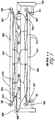
- FIGS. 1 through 7 Construction and operation of an illustrative treadmill of the present invention is shown in the various views presented in FIGS. 1 through 7 .
- the treadmill functions by mounting a series of cross beams 305 on two roller chains 308, one roller chain near each end of the beam as shown in FIG 7 .
- Cross beams 305 may be formed from a material such as aluminum.
- the roller chains 308 are assembled to form two parallel chains, each with a sprocket 204 on each end, the sprocket bearings being fixed to a frame 103. Movement of these beams on the chain assembly allow for movement in the x direction.
- a single helically wound conveyer belt 313 is employed for movement on the Y direction.
- Conveyor belt 313 may be formed from polyester monofilament plies with a PVC cover on the top side or equivalent materials. Conveyor belt 313 wraps around rollers 307 placed at both ends of each beam. On the outer surface of each beam the belt is kept in contact along the length of the beam by the beam employing a slight curvature shown at reference numeral 20. This curvature, which may be about 1.27 cm (0.5 inch) allows for bowing of the cross beams 305 due to the users weight without the conveyor belt 313 lifting off the surface due to a concavity.
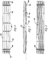
- Cross beams 305 could easily be molded from a thermoplastic plastic material such as Nylon 6/6, and may be shaped as shown in the various views presented in FIGS. 13, 14 and 15 . This version will result in a less expensive, lighter weight and easy to assemble cross beam 305.
- the conveyor belt 313 travels on the outside of the beam and moves towards the end roller 307. It then travels around that roller departing it on the inside.
- the belt 313 then starts a twisting motion while it passes between alignment rollers 318 then through a clip 309 that attaches to the cross beam 305 then on to one of the two roller chains 308 shown in FIG. 9 . It then pivots slightly around a vertically mounted roller 310 thereby slightly redirecting the belt towards the next cross beam as shown in FIG. 8 .
- the belt has now twisted 90 degrees.
- the belt then continues twisting and encounters the final roller of the current beam 312.
- Each beam has two belt transfers going on at once.
- One of the rollers 312 is for the conveyer belt moving to the cross beam in front of the current cross beam and the other one of the rollers 312 is for the conveyer belt coming from the cross beam behind the current one.
- roller 312 slightly redirects the conveyor belt. Roller 312 allows the belt to stay parallel to the cross beam 305 but held at about the same height as the sprocket teeth roller chain interface. The next roller 312 the belt encounters is parallel to the last one but is mounted on the next beam over. Upon encountering that roller the belt 313 is slightly redirected back down. The belt 313 continues twisting when it encounters another roller 310 that allows it to pivot parallel to longitudinal axis of the new beam. Persons of ordinary skill in the art will note that the conveyor belt has twisted 180° between the two rollers 310. It then continues with another 90° twist again passing through a clip 309 then alignment rollers 318 then encounters the end roller 307 of that beam.
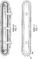
- FIG. 8 A bottom view of this conveyer belting assembly is shown in FIG. 8 .
- This somewhat helical wrapping of the conveyer belt 313 repeats for every beam. Therefore, only one (very long) endless conveyer belt is needed to provide y directional movement.
- the vertical rollers 309 are used to slightly redirect the conveyor belt allowing the end rollers 307 to be oriented exactly 90° from the length of the cross beam to allow the omnidirectional wheels to travel smoothly.
- the X directional movement is accomplished by powering the axle coupled to the sprockets 204 with an appropriately geared electric motor 104.
- Y directional movement is accomplished by omni-directional wheels 102 mounted on four drive shafts 101 geared together with each wheel 102 being pressed into the conveyor belt spinning around the end roller 307. Since each cross beam 305 has a roller 307 on each end, inward pressures on those wheels cancel each other out, therefore the amount of pressure exerted on each wheel could be quite substantial if desired, easily enough to produce enough friction to power the conveyor belt in the Y direction, even under high acceleration.
- the end roller/wheel interface is stabilized by the roller chain assembly on top and ball transfers 311 on the bottom.
- the cross beams are capable of being pinned together, this may be accomplished by attaching a tapered rod 314a on one side of the beam and a hole 314 on the other. This will allow each cross beam to provide and get support from the neighboring cross beams on either side, thus making the assembly behave more like a homogeneous structure when the user walks on it.
- Each cross beam is also provided with a small flange 316 protruding next to the conveyer belt on one side as shown in FIG. 9 .
- This flange 316 serves to help prevent the belt 313 from moving off the cross beam.
- the interfacing sides of the cross beams with the locating pins may be fashioned to have a small gap between them. This gap is to allow for a layer of a resilient material 315 such as rubber to be attached as shown in FIG. 9 .
- the omni-directional treadmill of the present invention can easily be mounted on a gimbal 416 or similar device and tilted in any direction using linear actuators 418 as shown in FIGS. 16 , 17, and 18 to simulate hills and to allow for an advanced motion control device.
- an illustrative dynamic control interface includes a floating frame 604 waist high with sliding attachments to four vertical tubes 601. There is a single cable traveling to all four of the vertical tubes via pulleys 602. This cable system forces the floating frame to stay level relative to the omni-directional treadmill. The amount of vertical force exerted on the floating frame can be controlled by a piston or actuator 606 connected to one of the vertical tubes 601.
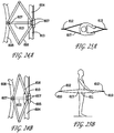
- FIGS. 24A and 24B Four bearing blocks 605 glide on the floating frame allowing a means of holding a hoop via four rods 603 or other mechanism such as four scissor connections 616 as shown in FIGS. 24A and 24B .
- Two independent cable systems consisting of pulleys 607 and cables 613 connect one side of the hoop to the opposite side.
- the cables of one system translate during X directional movement and one system's cables translate during Y directional movement.
- These systems allows for the hoop to move in the Y direction with no X cable translation and in the X direction with no Y cable translation.
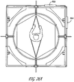
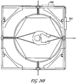
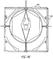
- the cable for each system runs through its own control unit, 614 for X and 615 for Y as shown in FIGS. 26A through 26D .
- the part of the cables that actually run through the control unit may be replaced by a roller chain or other means of mechanically interacting with the control unit.
- These units may contain an adjustable dampening device which gives the user a sense of inertia. They also easily could provide additional interfaces between the user and the speed control system of the omni-directional treadmill.
- FIG. 26A is a top view of the user in the neutral position on the treadmill. She is either not moving or in a steady state of movement.
- FIG. 26B is also a top view and shows the user in a movement in the X direction with a translation in that direction.
- FIG. 26C is a top view showing the user moving in the Y direction with a translation in that direction.
- the assembly is also capable of twisting inside the hoop via hoop rollers 610 and cable 609 thus allowing the user to turn as shown in FIG. 26D .
- This actuator could be a pneumatic or hydraulic piston connected to a plenum pressurized by a gas. By controlling the gas pressure, someone on the Earth could feel like they were on the Moon or someone on the Moon or in space could feel as if they weighed as much as they desired.
- the user To connect to the dynamic control interface, the user first needs to be wearing the harness 616 then, with the swivel harness fixture lowered, simply step into it, pull it up and snap in to the side pivot points 611.
Description
- The present invention relates to a treadmill in accordance with the preamble of claim 1, comprising subject-matter known from
US6152854A , that can be walked on in any direction without physically moving from one small area. The treadmill of the present invention will be able to greatly enhance the immerging technology of immersive virtual reality along with many other technologies. - Several types of omni-directional treadmills or similar functioning devices are known. One such treadmill is disclosed in United States Patent No.
7,780,573 and employs a plurality of high aspect ratio endless unpowered treadmills fixed together transverse to the plane of belt rotation enabling them to move together like the treads of a tank. The plurality of treadmills is then powered by having them pass over several omni-directional wheels that power the multitude of treadmills while allowing them to pass across the omni-directional wheels. - Another larger omni-directional treadmill is disclosed in United States Patent Publication number
20100022358 and uses the same concept of attaching a plurality of endless treadmills together and again move them like the treads of a tank. -
US 2010/147430 A1 discloses an omnidirectional contiguous moving surface that includes a belt layer made of a plurality of interlocking flexible rings and a surface layer made of a laterally inelastic and longitudinally flexible material that surrounds the exterior of the belt layer. -
WO 97/34663 A1 -
US 3 451 526 A discloses a conveyer system comprising a number of interengageable conveyer units in the form of two conveyers having a common coplanar area of intersection. - The present invention provides an omnidirectional treadmill according to claim 1. Unlike the prior art as exemplified by United States Patent No.
7,780,573 which requires multiple belts, the present invention is an omni-directional treadmill that employs only one conveyor belt and is much simpler in nature and simpler to build. Instead of having a separate conveyor belt for each treadmill segment, the omni-directional treadmill of the present invention employs a single conveyor belt. The present invention thereby provides the advantages of not needing an elaborate method to connect end rollers to transfer movement of one belt to the next, thus eliminating the need to individually adjust tensions on a multitude of belts. This single belt is fed from one high aspect ratio cross beam to the next. All cross beams are attached to two common roller chains positioned underneath and near the end of each beam. These common roller chains then move a flat track with sprockets at each end. - The cross beams attached to the roller chains are driven by a motor connected to the sprockets the chains go around. This will be referred to herein as the X direction. Y directional movement is produced via omnidirectional wheels placed adjacent to and touching the conveyor belt as it travels around the rollers attached to the cross beam ends.
- Control for the motors that power the omni-directional treadmill may be accomplished in several ways. One means would be to incorporate an infrared sensing device like an Xbox Kinect to keep track of the user's direction, speed and acceleration on the treadmill and using that information to keep the user balanced and mostly centered.
- While this is most likely sufficient for movement, it deprives the user of the inertia the user would normally feel if actually moving. For instance, normally if one were to run at full speed than abruptly stop without attempting to slow down, one would naturally fall forward or if at full speed one were to quickly change directions without leaning into the turn, one again would fall over. Of course natural balance keeps a person's feet under their center of gravity so this usually doesn't happen.
- On an omni-directional treadmill however, since there is relatively little actual movement, the user would never lean into a turn or have to lean back before stopping even if running fast. This most likely would give the user an inconsistent or slightly disconnected sensation.
- According to another aspect of the present invention, the omni-directional treadmill is designed such that it can tilt in both the X and Y directions. Tilting control can be tied to the speed controller, enabling the omni-directional treadmill to be programmed to tilt in proportion to a user's small acceleration. The omni-directional treadmill can be programed to tilt up in the direction of that acceleration if the user was increasing speed and down if reducing speed, tilting as high or low and lasting as long as the controlling acceleration dictates. This tilting forces the user to work a little harder just as if she actually were accelerating her own weight in the direction she was running or turning, giving her the anticipated feeling associated with acceleration.
- Another or additional way of controlling the treadmill of the present invention is to use a dynamic control interface. The illustrative control interface described here attaches the user to the machine via a swivel harness. The attachment allows the user to bend forward, sideways, jump up and pivot in any direction. It also allows her limited movement. This movement provides the controller with the user's position and acceleration. It also allows for a way of dampening her movement to simulate inertia. An additional feature of this system is that it provides a means to modify the user's apparent weight. She can weigh as much or as little as she desires via the harness interface. And still another feature is that it makes sure that the user cannot accidently run off the platform.
-
-
FIG. 1 is a front view of a person standing on a treadmill constructed in accordance with the present invention. -
FIG. 2 is a top view of the treadmill ofFIG. 1 in accordance with the present invention. -
FIG. 3 is a cut away view of a treadmill in accordance with the present invention taken in a direction parallel with the cross beam of the treadmill -
FIG. 4 is a cut away view of a treadmill in accordance with the present invention in a direction orthogonal to the direction of the cut away view ofFIG. 3 showing the cross beam at the roller chain attach location. -
FIG. 5 is a cut away view a treadmill in accordance with the present invention taken in the same direction as the view ofFIG. 4 showing the cross beams at the middle location. -
FIG. 6 is a partial bottom view of a treadmill in accordance with the present invention showing a group of four cross beams. -
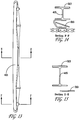
FIG. 7 is a side view of a single cross beam shown with a conveyer belt. -
FIG. 8 is a bottom view of four cross beams shown with a conveyer belt threading from one cross beam to another. -
FIG. 9 is a detailed view cut through a cross beam at a location showing a clip. -
FIG. 10 is a bottom end view of a cross beam showing a guide bracket with alignment rollers attached. -
FIG. 11 is a cross-sectional view of the cross beam end ofFIG. 10 next to a guide bracket taken through line D-D. -
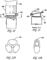
FIGS. 12A and 12B are, respectively, a side view and a front view of an omni-directional wheel. -
FIG. 13 is a side view of a plastic injection molded cross beam that may be used in a treadmill according to the present invention. -
FIG. 14 is a cross-sectional view of the cross beam ofFIG. 13 taken through lines F-F at the chain-attach location. -
FIG. 15 is a cross-sectional view through of the cross beam ofFIG. 13 taken through lines E-E at the center location showing the increased depth of the I beam. -
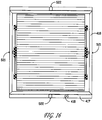
FIG. 16 is a top view of the treadmill employing a gimbal for inclining. -
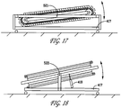
FIG. 17 is a front view of the gimbaled treadmill ofFIG. 16 . -
FIG. 18 is a side view of the gimbaled treadmill ofFIG. 16 . -
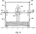
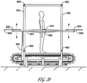
FIG. 19 is a front view of treadmill showing a dynamic control interface attached. -
FIG. 20 is a side view of the treadmill having the dynamic control interface ofFIG. 19 . -
FIG. 21 is a top view of treadmill ofFIG. 19 . -
FIG. 22 is a detailed view of a hoop-frame floating connection of the dynamic control interface. -
FIG. 23 is a diagram showing a hoop roller attach point of swivel harness fixture. -
FIGS. 24A and 24B are detailed views of a scissor hoop-frame floating connection of the dynamic control interface in an extended and retracted condition, respectively. -
FIGS. 25A and 25B are, respectively, top and side views showing a swivel harness assembly attached to user. -
FIGS. 26A through 26D are, respectively, top views of the dynamic control interface with a user not moving, the user moving in the X direction, the user moving in the Y direction, and the user rotating. - Persons of ordinary skill in the art will realize that the following description of the present invention is illustrative only and not in any way limiting. Other embodiments of the invention will readily suggest themselves to such skilled persons.
- Construction and operation of an illustrative treadmill of the present invention is shown in the various views presented in
FIGS. 1 through 7 . The treadmill functions by mounting a series of cross beams 305 on tworoller chains 308, one roller chain near each end of the beam as shown inFIG 7 . Cross beams 305 may be formed from a material such as aluminum. Theroller chains 308 are assembled to form two parallel chains, each with asprocket 204 on each end, the sprocket bearings being fixed to aframe 103. Movement of these beams on the chain assembly allow for movement in the x direction. For movement on the Y direction, a single helicallywound conveyer belt 313 is employed.Conveyor belt 313 may be formed from polyester monofilament plies with a PVC cover on the top side or equivalent materials.Conveyor belt 313 wraps aroundrollers 307 placed at both ends of each beam. On the outer surface of each beam the belt is kept in contact along the length of the beam by the beam employing a slight curvature shown atreference numeral 20. This curvature, which may be about 1.27 cm (0.5 inch) allows for bowing of the cross beams 305 due to the users weight without theconveyor belt 313 lifting off the surface due to a concavity. - Cross beams 305 could easily be molded from a thermoplastic plastic material such as Nylon 6/6, and may be shaped as shown in the various views presented in
FIGS. 13, 14 and 15 . This version will result in a less expensive, lighter weight and easy to assemblecross beam 305. - The description of movement of the
conveyor belt 313 relative to the cross beams 305 will now be described. Theconveyor belt 313 travels on the outside of the beam and moves towards theend roller 307. It then travels around that roller departing it on the inside. Thebelt 313 then starts a twisting motion while it passes betweenalignment rollers 318 then through aclip 309 that attaches to thecross beam 305 then on to one of the tworoller chains 308 shown inFIG. 9 . It then pivots slightly around a vertically mountedroller 310 thereby slightly redirecting the belt towards the next cross beam as shown inFIG. 8 . At this station, the belt has now twisted 90 degrees. The belt then continues twisting and encounters the final roller of thecurrent beam 312. Each beam has two belt transfers going on at once. One of therollers 312 is for the conveyer belt moving to the cross beam in front of the current cross beam and the other one of therollers 312 is for the conveyer belt coming from the cross beam behind the current one. - The
roller 312 slightly redirects the conveyor belt.Roller 312 allows the belt to stay parallel to thecross beam 305 but held at about the same height as the sprocket teeth roller chain interface. Thenext roller 312 the belt encounters is parallel to the last one but is mounted on the next beam over. Upon encountering that roller thebelt 313 is slightly redirected back down. Thebelt 313 continues twisting when it encounters anotherroller 310 that allows it to pivot parallel to longitudinal axis of the new beam. Persons of ordinary skill in the art will note that the conveyor belt has twisted 180° between the tworollers 310. It then continues with another 90° twist again passing through aclip 309 thenalignment rollers 318 then encounters theend roller 307 of that beam. A bottom view of this conveyer belting assembly is shown inFIG. 8 . This somewhat helical wrapping of theconveyer belt 313 repeats for every beam. Therefore, only one (very long) endless conveyer belt is needed to provide y directional movement. Thevertical rollers 309 are used to slightly redirect the conveyor belt allowing theend rollers 307 to be oriented exactly 90° from the length of the cross beam to allow the omnidirectional wheels to travel smoothly. - When the cross beam/belt assembly is at the end of the flat part of its travel when traveling in the X direction and the
roller chain 308 encounters thesprocket 204 it then must rotate. Thebelt 313 is able to accomplish this because when traveling between cross beams at a location between the pair ofrollers 312 it is at thesame radius 306 as theroller chain 308 and therefore will simply twist as the two cross beams that it is passing between twist relative to each other as shown inFIGS. 4 and 5 . - The X directional movement is accomplished by powering the axle coupled to the
sprockets 204 with an appropriately gearedelectric motor 104. Y directional movement is accomplished by omni-directional wheels 102 mounted on fourdrive shafts 101 geared together with eachwheel 102 being pressed into the conveyor belt spinning around theend roller 307. Since eachcross beam 305 has aroller 307 on each end, inward pressures on those wheels cancel each other out, therefore the amount of pressure exerted on each wheel could be quite substantial if desired, easily enough to produce enough friction to power the conveyor belt in the Y direction, even under high acceleration. The end roller/wheel interface is stabilized by the roller chain assembly on top andball transfers 311 on the bottom. - For additional support, the cross beams are capable of being pinned together, this may be accomplished by attaching a tapered
rod 314a on one side of the beam and ahole 314 on the other. This will allow each cross beam to provide and get support from the neighboring cross beams on either side, thus making the assembly behave more like a homogeneous structure when the user walks on it. - Each cross beam is also provided with a
small flange 316 protruding next to the conveyer belt on one side as shown inFIG. 9 . Thisflange 316 serves to help prevent thebelt 313 from moving off the cross beam. - To help reduce noise and vibration, the interfacing sides of the cross beams with the locating pins may be fashioned to have a small gap between them. This gap is to allow for a layer of a
resilient material 315 such as rubber to be attached as shown inFIG. 9 . - The omni-directional treadmill of the present invention can easily be mounted on a
gimbal 416 or similar device and tilted in any direction usinglinear actuators 418 as shown inFIGS. 16 ,17, and 18 to simulate hills and to allow for an advanced motion control device. - Referring now generally to
FIGS. 19 ,20 , and21 , an illustrative dynamic control interface includes a floatingframe 604 waist high with sliding attachments to fourvertical tubes 601. There is a single cable traveling to all four of the vertical tubes viapulleys 602. This cable system forces the floating frame to stay level relative to the omni-directional treadmill. The amount of vertical force exerted on the floating frame can be controlled by a piston oractuator 606 connected to one of thevertical tubes 601. - Four bearing blocks 605 glide on the floating frame allowing a means of holding a hoop via four
rods 603 or other mechanism such as fourscissor connections 616 as shown inFIGS. 24A and 24B . Two independent cable systems consisting ofpulleys 607 andcables 613 connect one side of the hoop to the opposite side. The cables of one system translate during X directional movement and one system's cables translate during Y directional movement. These systems allows for the hoop to move in the Y direction with no X cable translation and in the X direction with no Y cable translation. The cable for each system runs through its own control unit, 614 for X and 615 for Y as shown inFIGS. 26A through 26D . The part of the cables that actually run through the control unit may be replaced by a roller chain or other means of mechanically interacting with the control unit. These units may contain an adjustable dampening device which gives the user a sense of inertia. They also easily could provide additional interfaces between the user and the speed control system of the omni-directional treadmill. - The user wears a
harness 616 which incorporates two side pivot points 611 at the hip locations. These pins attach the harness to thepivot harness assembly 617. The pivot harness attaches to two hoop roller attach points through front and back swivelingconnections 612. This assembly allows the user to pivot both front and back and sideways.FIG. 26A is a top view of the user in the neutral position on the treadmill. She is either not moving or in a steady state of movement.FIG. 26B is also a top view and shows the user in a movement in the X direction with a translation in that direction.FIG. 26C is a top view showing the user moving in the Y direction with a translation in that direction. The assembly is also capable of twisting inside the hoop viahoop rollers 610 andcable 609 thus allowing the user to turn as shown inFIG. 26D . - Due to the nature of the dynamic control interface, when the user is connected in, she can be made to feel any weight sensation desirable by applying the appropriate force through the
vertical actuator 606. This actuator could be a pneumatic or hydraulic piston connected to a plenum pressurized by a gas. By controlling the gas pressure, someone on the Earth could feel like they were on the Moon or someone on the Moon or in space could feel as if they weighed as much as they desired. - To connect to the dynamic control interface, the user first needs to be wearing the
harness 616 then, with the swivel harness fixture lowered, simply step into it, pull it up and snap in to the side pivot points 611.
Claims (9)
- An omnidirectional treadmill comprising:a frame (103);a plurality of cross beams (305) coupled to one another to form a continuous loop having a substantially flat upper surface;a cross-beam drive mechanism (104) mounted to the frame (103) and coupled to the plurality of cross beams (305) to drive the continuous loop;a conveyor belt (313) wound around each cross beam (305) along the length of said each cross beam (305); anda conveyor-belt drive mechanism (101, 102) coupled to the conveyor belt (313),
characterized in thata single conveyor belt (313) is helically wound around the plurality of cross beams (305) and passes between each two adjacent cross beams (305) at an underside thereof. - The omnidirectional treadmill of claim 1, wherein the plurality of cross beams (305) are coupled to one another by being mounted on first and second drive chains (308), the first drive chain mounted between a first pair of sprocketed wheels (204) and the second drive chain mounted between a second pair of sprocketed wheels, a first end of each cross beam (305) mounted to the first drive chain and a second end of each cross beam mounted to the second drive chain, opposing ones of the first and second pair of sprocketed wheels (204) each mounted on a common axle supported by an axle frame coupled to the frame (103).
- The omnidirectional treadmill of claim 2 further comprising a drive motor coupled to one of the common axles of the sprocketed wheels (204).
- The omnidirectional treadmill of claim 1 wherein each cross beam (305) has a hole formed in one side face at a selected position along its length and a rod extending out of a second face opposing the first face at the selected position, the rod of each cross beam (305) extending into the hole of an adjacent cross beam.
- The omnidirectional treadmill of claim 1 further comprising a belt drive motor (104) coupled to the single conveyor belt.
- The omnidirectional treadmill of claim 1 further comprising a tilt actuator (418) coupled between the frame and the axle frame to tilt the substantially flat upper surface of the continuous loop at an angle disposed for a horizontal plane.
- The omnidirectional treadmill of claim 6 wherein the axle frame is mounted to the frame (103) at a pair of opposed pivot points.
- The omnidirectional treadmill of claim 1 further comprising a user harness (616) mounted to the frame (103).
- The omnidirectional treadmill of claim 1 further comprising:a dynamic control interface that includes a floating frame (604) having sliding attachments to four vertical supports (601), a single cable traveling to all four of the vertical supports via pulleys (602) to force the floating frame to remain level relative to the omnidirectional treadmill; andan actuator (606) coupled to one of the vertical supports to control the amount of vertical force exerted on the floating frame.
Applications Claiming Priority (3)
| Application Number | Priority Date | Filing Date | Title |
|---|---|---|---|
| US40053510P | 2010-07-29 | 2010-07-29 | |
| US13/193,511 US8790222B2 (en) | 2010-07-29 | 2011-07-28 | Single belt omni directional treadmill |
| PCT/US2011/045875 WO2012016132A1 (en) | 2010-07-29 | 2011-07-29 | Single belt omni directional treadmill |
Publications (3)
| Publication Number | Publication Date |
|---|---|
| EP2588205A1 EP2588205A1 (en) | 2013-05-08 |
| EP2588205A4 EP2588205A4 (en) | 2013-12-25 |
| EP2588205B1 true EP2588205B1 (en) | 2017-05-31 |
Family
ID=45530501
Family Applications (1)
| Application Number | Title | Priority Date | Filing Date |
|---|---|---|---|
| EP11813239.8A Active EP2588205B1 (en) | 2010-07-29 | 2011-07-29 | Single belt omni directional treadmill |
Country Status (14)
| Country | Link |
|---|---|
| US (2) | US8790222B2 (en) |
| EP (1) | EP2588205B1 (en) |
| JP (1) | JP5826843B2 (en) |
| KR (1) | KR101629544B1 (en) |
| CN (1) | CN103402587B (en) |
| AU (1) | AU2011282572B2 (en) |
| BR (1) | BR112013002142A2 (en) |
| CA (1) | CA2806988C (en) |
| ES (1) | ES2637289T3 (en) |
| IL (1) | IL224448A (en) |
| NZ (1) | NZ607453A (en) |
| RU (1) | RU2563789C2 (en) |
| SG (1) | SG187616A1 (en) |
| WO (1) | WO2012016132A1 (en) |
Cited By (1)
| Publication number | Priority date | Publication date | Assignee | Title |
|---|---|---|---|---|
| CN110270051A (en) * | 2019-05-29 | 2019-09-24 | 北京七鑫易维信息技术有限公司 | Balance control method, device, omnidirectional's treadmill and the medium of omnidirectional's treadmill |
Families Citing this family (69)
| Publication number | Priority date | Publication date | Assignee | Title |
|---|---|---|---|---|
| US10183191B2 (en) * | 2009-11-02 | 2019-01-22 | Speedfit LLC | Leg-powered treadmill |
| US9056240B2 (en) * | 2012-03-09 | 2015-06-16 | Matthew Carrell | Apparatus for simulating motion in a virtual environment |
| JP5995585B2 (en) * | 2012-07-27 | 2016-09-21 | 学校法人順天堂 | Exercise equipment |
| EP2969058B1 (en) | 2013-03-14 | 2020-05-13 | Icon Health & Fitness, Inc. | Strength training apparatus with flywheel and related methods |
| US9480871B2 (en) * | 2013-03-15 | 2016-11-01 | Michael H. DOMESICK | Belt-based system for strengthening muscles |
| EP3974036A1 (en) | 2013-12-26 | 2022-03-30 | iFIT Inc. | Magnetic resistance mechanism in a cable machine |
| WO2015138339A1 (en) | 2014-03-10 | 2015-09-17 | Icon Health & Fitness, Inc. | Pressure sensor to quantify work |
| WO2015191445A1 (en) | 2014-06-09 | 2015-12-17 | Icon Health & Fitness, Inc. | Cable system incorporated into a treadmill |
| US20150352401A1 (en) * | 2014-06-10 | 2015-12-10 | Susan Michelle Johnson | Moving portable dance floor |
| EP3177371A1 (en) | 2014-08-04 | 2017-06-14 | Porteros De Luz, Veronica | Cable treadmill |
| US9616278B2 (en) * | 2014-08-29 | 2017-04-11 | Icon Health & Fitness, Inc. | Laterally tilting treadmill deck |
| US9675839B2 (en) * | 2014-11-26 | 2017-06-13 | Icon Health & Fitness, Inc. | Treadmill with a tensioning mechanism for a slatted tread belt |
| US10258828B2 (en) | 2015-01-16 | 2019-04-16 | Icon Health & Fitness, Inc. | Controls for an exercise device |
| CN104667488B (en) * | 2015-02-11 | 2017-10-10 | 深圳威阿科技有限公司 | The method and system that omnirange displacement is offset is produced in motion platform |
| KR101672702B1 (en) * | 2015-04-30 | 2016-11-16 | 한국기계연구원 | Two-Dimensional Treadmill Using Side Omni-Ball |
| KR101672705B1 (en) * | 2015-04-30 | 2016-11-07 | 한국기계연구원 | Two-Dimensional Treadmill Using Side-Belt |
| KR101670718B1 (en) | 2015-05-29 | 2016-10-31 | 경상대학교산학협력단 | Omni-directional treadmill apparatus |
| USD840400S1 (en) * | 2015-06-16 | 2019-02-12 | Hang Zhou Yike Technology Ltd. | Virtual reality human omnidirectional mobile input platform |
| US10953305B2 (en) | 2015-08-26 | 2021-03-23 | Icon Health & Fitness, Inc. | Strength exercise mechanisms |
| US10212994B2 (en) | 2015-11-02 | 2019-02-26 | Icon Health & Fitness, Inc. | Smart watch band |
| CN105468154B (en) * | 2015-11-25 | 2018-06-19 | 国网浙江省电力有限公司台州供电公司 | The interactive panorama display systems of electric system operation |
| KR101778588B1 (en) | 2015-11-30 | 2017-09-15 | 한국기계연구원 | Omnidirectional Motion Generation Device Using Omnidirectional Omni Drive Ball Assembly |
| US10350450B2 (en) | 2016-01-13 | 2019-07-16 | John Stelmach | Lateral tilting treadmill systems |
| US20170252623A1 (en) * | 2016-03-02 | 2017-09-07 | Christian Sharifi | Ice skating training systems |
| US10272317B2 (en) | 2016-03-18 | 2019-04-30 | Icon Health & Fitness, Inc. | Lighted pace feature in a treadmill |
| US10493349B2 (en) | 2016-03-18 | 2019-12-03 | Icon Health & Fitness, Inc. | Display on exercise device |
| US10561894B2 (en) | 2016-03-18 | 2020-02-18 | Icon Health & Fitness, Inc. | Treadmill with removable supports |
| US10625137B2 (en) | 2016-03-18 | 2020-04-21 | Icon Health & Fitness, Inc. | Coordinated displays in an exercise device |
| US10293211B2 (en) | 2016-03-18 | 2019-05-21 | Icon Health & Fitness, Inc. | Coordinated weight selection |
| KR20170121682A (en) * | 2016-04-25 | 2017-11-02 | 주식회사 디랙스 | Treadmill |
| WO2017192904A2 (en) * | 2016-05-04 | 2017-11-09 | Nautilus, Inc. | Exercise machine and user interface for exercise machine |
| US10252109B2 (en) | 2016-05-13 | 2019-04-09 | Icon Health & Fitness, Inc. | Weight platform treadmill |
| US10471299B2 (en) | 2016-07-01 | 2019-11-12 | Icon Health & Fitness, Inc. | Systems and methods for cooling internal exercise equipment components |
| US10441844B2 (en) | 2016-07-01 | 2019-10-15 | Icon Health & Fitness, Inc. | Cooling systems and methods for exercise equipment |
| KR102530259B1 (en) * | 2016-07-21 | 2023-05-09 | 한국기계연구원 | 2-dimensional treadmill using side geared belt assembly |
| CN106110573B (en) * | 2016-07-28 | 2019-05-14 | 京东方科技集团股份有限公司 | Omni-mobile platform and its control method, treadmill |
| US10080951B2 (en) | 2016-08-19 | 2018-09-25 | International Business Machines Corporation | Simulating virtual topography using treadmills |
| US10500473B2 (en) | 2016-10-10 | 2019-12-10 | Icon Health & Fitness, Inc. | Console positioning |
| US10376736B2 (en) | 2016-10-12 | 2019-08-13 | Icon Health & Fitness, Inc. | Cooling an exercise device during a dive motor runway condition |
| TWI646997B (en) | 2016-11-01 | 2019-01-11 | 美商愛康運動與健康公司 | Distance sensor for console positioning |
| US10661114B2 (en) | 2016-11-01 | 2020-05-26 | Icon Health & Fitness, Inc. | Body weight lift mechanism on treadmill |
| TWI680782B (en) | 2016-12-05 | 2020-01-01 | 美商愛康運動與健康公司 | Offsetting treadmill deck weight during operation |
| US10569123B2 (en) * | 2016-12-05 | 2020-02-25 | Icon Health & Fitness, Inc. | Deck adjustment interface |
| US10259653B2 (en) | 2016-12-15 | 2019-04-16 | Feedback, LLC | Platforms for omnidirectional movement |
| EP3538227B1 (en) | 2016-12-27 | 2020-07-01 | Rudelstorfer, Elmar | Omnidirectional treadmill |
| DK179549B1 (en) | 2017-05-16 | 2019-02-12 | Apple Inc. | Far-field extension for digital assistant services |
| TWI722450B (en) | 2017-08-16 | 2021-03-21 | 美商愛康運動與健康公司 | System for opposing axial impact loading in a motor |
| WO2019039854A1 (en) * | 2017-08-24 | 2019-02-28 | 주식회사 톨레미시스템 | Method for supporting rehabilitation by using forward moving platform |
| US10444827B2 (en) * | 2017-09-18 | 2019-10-15 | Fujitsu Limited | Platform for virtual reality movement |
| CN107854807B (en) * | 2017-11-27 | 2023-06-30 | 北京小米移动软件有限公司 | Running board assembly and running machine |
| CN107773913B (en) | 2017-11-27 | 2020-09-11 | 北京小米移动软件有限公司 | Running board assembly and treadmill |
| US10729965B2 (en) | 2017-12-22 | 2020-08-04 | Icon Health & Fitness, Inc. | Audible belt guide in a treadmill |
| USD854101S1 (en) | 2018-01-05 | 2019-07-16 | Peloton Interactive, Inc. | Treadmill |
| KR101883827B1 (en) * | 2018-01-26 | 2018-08-01 | 주식회사 위저드 | Treadmill |
| US11413499B2 (en) * | 2018-03-09 | 2022-08-16 | Nicholas Maroldi | Device to produce assisted, active and resisted motion of a joint or extremity |
| CN108295451A (en) * | 2018-04-04 | 2018-07-20 | 西华大学 | A kind of indoor rock-climbing machine |
| US10632339B2 (en) * | 2018-04-13 | 2020-04-28 | Yi-Tzu Chen | Treadmill |
| CN108525206B (en) * | 2018-06-07 | 2023-07-18 | 上海永利输送系统有限公司 | Spring damping treadmill belt and treadmill |
| CN109248415B (en) * | 2018-08-14 | 2020-09-11 | 东南大学 | Roller type human body omnidirectional motion platform and speed synthesis method thereof |
| US10732197B2 (en) * | 2018-09-19 | 2020-08-04 | Disney Enterprises, Inc. | System for stabilizing an object to control tipping during omnidirectional movement |
| WO2020106369A2 (en) * | 2018-10-02 | 2020-05-28 | The Omnipad Company, Llc | Omnidirectional moving surface including motor drive |
| AT522019B1 (en) | 2019-01-11 | 2021-01-15 | Cyberith Gmbh | Device for the simulated locomotion of a user |
| KR102300669B1 (en) * | 2019-08-22 | 2021-09-09 | 소호성 | Omni-directional treadmill |
| DE102020133383B4 (en) | 2020-12-14 | 2023-12-07 | Deutsches Zentrum für Luft- und Raumfahrt e.V. | Omnidirectional wheel and robotic system |
| CN112973042A (en) * | 2021-03-30 | 2021-06-18 | 上海厘成智能科技有限公司 | Man-machine integrated treadmill control method |
| KR102525750B1 (en) * | 2021-08-12 | 2023-04-27 | 광주과학기술원 | Omnidirectional treadmill apparatus |
| CN114275455B (en) * | 2021-12-28 | 2024-01-23 | 广东工业大学 | Short-delay 360-degree walking device and control method thereof |
| WO2023133158A1 (en) * | 2022-01-04 | 2023-07-13 | The Omnipad Company, Llc | Powered omnipad platform |
| US11954246B2 (en) * | 2022-07-06 | 2024-04-09 | Walter L. Terry | Smart individual motion capture and spatial translation (SIMCAST) system |
Family Cites Families (24)
| Publication number | Priority date | Publication date | Assignee | Title |
|---|---|---|---|---|
| US3451526A (en) | 1967-03-03 | 1969-06-24 | John Fernandez | Conveyor systems |
| US4635927A (en) * | 1985-03-04 | 1987-01-13 | Del Mar Avionics | Low power treadmill |
| US5385520A (en) | 1992-05-28 | 1995-01-31 | Hockey Acceleration, Inc. | Ice skating treadmill |
| US5667461A (en) | 1994-07-06 | 1997-09-16 | Hall; Raymond F. | Ambulatory traction assembly |
| US6123647A (en) * | 1996-03-20 | 2000-09-26 | Mitchell; Andrew John | Motion apparatus |
| US6152854A (en) * | 1996-08-27 | 2000-11-28 | Carmein; David E. E. | Omni-directional treadmill |
| US6042514A (en) * | 1998-05-30 | 2000-03-28 | Abelbeck; Kevin G. | Moving surface exercise device |
| US6053848A (en) | 1998-08-24 | 2000-04-25 | Eschenbach; Paul William | Treadmill deck suspension |
| US6821230B2 (en) * | 1998-09-25 | 2004-11-23 | Icon Ip, Inc. | Treadmill with adjustable cushioning members |
| US6554747B1 (en) * | 2001-03-30 | 2003-04-29 | Douglas F. Rempe | Exercise device and method of use thereof |
| US6743154B2 (en) * | 2001-06-01 | 2004-06-01 | Neil B. Epstein | Omnidirectional moving surface |
| HRP20020713A2 (en) * | 2001-09-06 | 2003-06-30 | Vt Zurich Marketing Pte Ltd | Conveyor for containers provided with lateral aperture designed for transport |
| US20040106504A1 (en) * | 2002-09-03 | 2004-06-03 | Leonard Reiffel | Mobile interactive virtual reality product |
| CN2652449Y (en) * | 2003-10-17 | 2004-11-03 | 李铁军 | Inclined angle adjustable treadmill |
| US20050148432A1 (en) * | 2003-11-03 | 2005-07-07 | Carmein David E.E. | Combined omni-directional treadmill and electronic perception technology |
| KR200369636Y1 (en) | 2004-08-31 | 2004-12-09 | 알릴리페 인더스트리얼 주식회사 | treadmill |
| US7780573B1 (en) * | 2006-01-31 | 2010-08-24 | Carmein David E E | Omni-directional treadmill with applications |
| DE102006040485A1 (en) | 2006-08-30 | 2008-03-20 | Technische Universität München | Device with a movable in two directions surface |
| EP2099534A1 (en) * | 2007-11-08 | 2009-09-16 | Karl Müller | Training device |
| US7878284B1 (en) | 2007-11-29 | 2011-02-01 | Shultz Jonathan D | Omni-directional tread and contiguous moving surface |
| US7624858B2 (en) * | 2007-12-21 | 2009-12-01 | Habasit Ag | Modular plastic conveyor belt for spiral conversion |
| KR20100011394U (en) * | 2009-05-14 | 2010-11-24 | 김재영 | Non Electric Running Machine |
| US20100304936A1 (en) * | 2009-05-28 | 2010-12-02 | Shuei Mu Wang | Conveyor belt or treadmill belt |
| EP2275367A3 (en) * | 2009-07-13 | 2012-07-25 | Ammeraal Beltech Modular A/S | Modular belt conveyor, in particular a curving or helical conveyor |
-
2011
- 2011-07-28 US US13/193,511 patent/US8790222B2/en active Active
- 2011-07-29 KR KR1020137004993A patent/KR101629544B1/en active IP Right Grant
- 2011-07-29 JP JP2013521999A patent/JP5826843B2/en active Active
- 2011-07-29 WO PCT/US2011/045875 patent/WO2012016132A1/en active Application Filing
- 2011-07-29 EP EP11813239.8A patent/EP2588205B1/en active Active
- 2011-07-29 CA CA2806988A patent/CA2806988C/en active Active
- 2011-07-29 RU RU2013108805/12A patent/RU2563789C2/en active
- 2011-07-29 CN CN201180045032.8A patent/CN103402587B/en active Active
- 2011-07-29 BR BR112013002142A patent/BR112013002142A2/en not_active IP Right Cessation
- 2011-07-29 NZ NZ607453A patent/NZ607453A/en not_active IP Right Cessation
- 2011-07-29 AU AU2011282572A patent/AU2011282572B2/en not_active Ceased
- 2011-07-29 ES ES11813239.8T patent/ES2637289T3/en active Active
- 2011-07-29 SG SG2013006432A patent/SG187616A1/en unknown
-
2013
- 2013-01-28 IL IL224448A patent/IL224448A/en not_active IP Right Cessation
-
2014
- 2014-07-29 US US14/445,705 patent/US20140336010A1/en not_active Abandoned
Cited By (1)
| Publication number | Priority date | Publication date | Assignee | Title |
|---|---|---|---|---|
| CN110270051A (en) * | 2019-05-29 | 2019-09-24 | 北京七鑫易维信息技术有限公司 | Balance control method, device, omnidirectional's treadmill and the medium of omnidirectional's treadmill |
Also Published As
| Publication number | Publication date |
|---|---|
| KR20130044342A (en) | 2013-05-02 |
| RU2563789C2 (en) | 2015-09-20 |
| RU2013108805A (en) | 2014-09-10 |
| EP2588205A4 (en) | 2013-12-25 |
| AU2011282572B2 (en) | 2015-01-29 |
| US20120302408A1 (en) | 2012-11-29 |
| SG187616A1 (en) | 2013-03-28 |
| BR112013002142A2 (en) | 2016-05-24 |
| CN103402587B (en) | 2016-01-20 |
| IL224448A (en) | 2015-09-24 |
| NZ607453A (en) | 2014-08-29 |
| CA2806988A1 (en) | 2012-02-02 |
| JP5826843B2 (en) | 2015-12-02 |
| US20140336010A1 (en) | 2014-11-13 |
| KR101629544B1 (en) | 2016-06-13 |
| ES2637289T3 (en) | 2017-10-11 |
| WO2012016132A1 (en) | 2012-02-02 |
| CN103402587A (en) | 2013-11-20 |
| AU2011282572A1 (en) | 2013-02-21 |
| EP2588205A1 (en) | 2013-05-08 |
| JP2013535280A (en) | 2013-09-12 |
| US8790222B2 (en) | 2014-07-29 |
| CA2806988C (en) | 2016-01-26 |
Similar Documents
| Publication | Publication Date | Title |
|---|---|---|
| EP2588205B1 (en) | Single belt omni directional treadmill | |
| US7922625B2 (en) | Adaptive motion exercise device with oscillating track | |
| EP3509712B1 (en) | Apparatus for omnidirectional locomotion | |
| US9586085B2 (en) | Exercise apparatus with non-uniform foot pad transverse spacing | |
| CN101822890B (en) | Adaptive motion exercise device with plural crank assemblies | |
| JP5695581B2 (en) | Apparatus and method for transporting items between conveyors | |
| EP0892658B1 (en) | Motion apparatus | |
| US20100022358A1 (en) | Device having a surface displaceable in two spatial directions | |
| KR101550814B1 (en) | Step type bipedal locomotion | |
| EP0334608A2 (en) | Treadmill with trampoline-like surface | |
| US6220172B1 (en) | Camera track system and controls therefor | |
| GB2311976A (en) | Omni-directional Treadmill | |
| KR102630812B1 (en) | Motorless treadmill | |
| AU767788B2 (en) | Motion apparatus | |
| CA2249309C (en) | Motion apparatus | |
| KR20150093454A (en) | Bipedal locomotion having variable foothold and bipedal locomotion assembly | |
| JPH11347147A (en) | Walk training machine | |
| US20150283422A1 (en) | Stepper with tread interconnect | |
| GB2338426A (en) | Rolling sphere propulsion unit |
Legal Events
| Date | Code | Title | Description |
|---|---|---|---|
| PUAI | Public reference made under article 153(3) epc to a published international application that has entered the european phase |
Free format text: ORIGINAL CODE: 0009012 |
|
| 17P | Request for examination filed |
Effective date: 20130204 |
|
| AK | Designated contracting states |
Kind code of ref document: A1 Designated state(s): AL AT BE BG CH CY CZ DE DK EE ES FI FR GB GR HR HU IE IS IT LI LT LU LV MC MK MT NL NO PL PT RO RS SE SI SK SM TR |
|
| DAX | Request for extension of the european patent (deleted) | ||
| A4 | Supplementary search report drawn up and despatched |
Effective date: 20131126 |
|
| RIC1 | Information provided on ipc code assigned before grant |
Ipc: A63B 22/02 20060101AFI20131120BHEP |
|
| REG | Reference to a national code |
Ref country code: HK Ref legal event code: DE Ref document number: 1185300 Country of ref document: HK |
|
| GRAP | Despatch of communication of intention to grant a patent |
Free format text: ORIGINAL CODE: EPIDOSNIGR1 |
|
| INTG | Intention to grant announced |
Effective date: 20161213 |
|
| GRAS | Grant fee paid |
Free format text: ORIGINAL CODE: EPIDOSNIGR3 |
|
| GRAA | (expected) grant |
Free format text: ORIGINAL CODE: 0009210 |
|
| AK | Designated contracting states |
Kind code of ref document: B1 Designated state(s): AL AT BE BG CH CY CZ DE DK EE ES FI FR GB GR HR HU IE IS IT LI LT LU LV MC MK MT NL NO PL PT RO RS SE SI SK SM TR |
|
| REG | Reference to a national code |
Ref country code: CH Ref legal event code: EP Ref country code: GB Ref legal event code: FG4D |
|
| REG | Reference to a national code |
Ref country code: AT Ref legal event code: REF Ref document number: 896897 Country of ref document: AT Kind code of ref document: T Effective date: 20170615 |
|
| REG | Reference to a national code |
Ref country code: IE Ref legal event code: FG4D |
|
| REG | Reference to a national code |
Ref country code: DE Ref legal event code: R096 Ref document number: 602011038410 Country of ref document: DE |
|
| REG | Reference to a national code |
Ref country code: FR Ref legal event code: PLFP Year of fee payment: 7 |
|
| REG | Reference to a national code |
Ref country code: NL Ref legal event code: MP Effective date: 20170531 |
|
| REG | Reference to a national code |
Ref country code: LT Ref legal event code: MG4D |
|
| REG | Reference to a national code |
Ref country code: ES Ref legal event code: FG2A Ref document number: 2637289 Country of ref document: ES Kind code of ref document: T3 Effective date: 20171011 |
|
| REG | Reference to a national code |
Ref country code: AT Ref legal event code: MK05 Ref document number: 896897 Country of ref document: AT Kind code of ref document: T Effective date: 20170531 |
|
| PG25 | Lapsed in a contracting state [announced via postgrant information from national office to epo] |
Ref country code: GR Free format text: LAPSE BECAUSE OF FAILURE TO SUBMIT A TRANSLATION OF THE DESCRIPTION OR TO PAY THE FEE WITHIN THE PRESCRIBED TIME-LIMIT Effective date: 20170901 Ref country code: FI Free format text: LAPSE BECAUSE OF FAILURE TO SUBMIT A TRANSLATION OF THE DESCRIPTION OR TO PAY THE FEE WITHIN THE PRESCRIBED TIME-LIMIT Effective date: 20170531 Ref country code: AT Free format text: LAPSE BECAUSE OF FAILURE TO SUBMIT A TRANSLATION OF THE DESCRIPTION OR TO PAY THE FEE WITHIN THE PRESCRIBED TIME-LIMIT Effective date: 20170531 Ref country code: NO Free format text: LAPSE BECAUSE OF FAILURE TO SUBMIT A TRANSLATION OF THE DESCRIPTION OR TO PAY THE FEE WITHIN THE PRESCRIBED TIME-LIMIT Effective date: 20170831 Ref country code: LT Free format text: LAPSE BECAUSE OF FAILURE TO SUBMIT A TRANSLATION OF THE DESCRIPTION OR TO PAY THE FEE WITHIN THE PRESCRIBED TIME-LIMIT Effective date: 20170531 Ref country code: HR Free format text: LAPSE BECAUSE OF FAILURE TO SUBMIT A TRANSLATION OF THE DESCRIPTION OR TO PAY THE FEE WITHIN THE PRESCRIBED TIME-LIMIT Effective date: 20170531 |
|
| PG25 | Lapsed in a contracting state [announced via postgrant information from national office to epo] |
Ref country code: BG Free format text: LAPSE BECAUSE OF FAILURE TO SUBMIT A TRANSLATION OF THE DESCRIPTION OR TO PAY THE FEE WITHIN THE PRESCRIBED TIME-LIMIT Effective date: 20170831 Ref country code: LV Free format text: LAPSE BECAUSE OF FAILURE TO SUBMIT A TRANSLATION OF THE DESCRIPTION OR TO PAY THE FEE WITHIN THE PRESCRIBED TIME-LIMIT Effective date: 20170531 Ref country code: SE Free format text: LAPSE BECAUSE OF FAILURE TO SUBMIT A TRANSLATION OF THE DESCRIPTION OR TO PAY THE FEE WITHIN THE PRESCRIBED TIME-LIMIT Effective date: 20170531 Ref country code: IS Free format text: LAPSE BECAUSE OF FAILURE TO SUBMIT A TRANSLATION OF THE DESCRIPTION OR TO PAY THE FEE WITHIN THE PRESCRIBED TIME-LIMIT Effective date: 20170930 Ref country code: NL Free format text: LAPSE BECAUSE OF FAILURE TO SUBMIT A TRANSLATION OF THE DESCRIPTION OR TO PAY THE FEE WITHIN THE PRESCRIBED TIME-LIMIT Effective date: 20170531 Ref country code: RS Free format text: LAPSE BECAUSE OF FAILURE TO SUBMIT A TRANSLATION OF THE DESCRIPTION OR TO PAY THE FEE WITHIN THE PRESCRIBED TIME-LIMIT Effective date: 20170531 |
|
| PG25 | Lapsed in a contracting state [announced via postgrant information from national office to epo] |
Ref country code: DK Free format text: LAPSE BECAUSE OF FAILURE TO SUBMIT A TRANSLATION OF THE DESCRIPTION OR TO PAY THE FEE WITHIN THE PRESCRIBED TIME-LIMIT Effective date: 20170531 Ref country code: EE Free format text: LAPSE BECAUSE OF FAILURE TO SUBMIT A TRANSLATION OF THE DESCRIPTION OR TO PAY THE FEE WITHIN THE PRESCRIBED TIME-LIMIT Effective date: 20170531 Ref country code: RO Free format text: LAPSE BECAUSE OF FAILURE TO SUBMIT A TRANSLATION OF THE DESCRIPTION OR TO PAY THE FEE WITHIN THE PRESCRIBED TIME-LIMIT Effective date: 20170531 Ref country code: SK Free format text: LAPSE BECAUSE OF FAILURE TO SUBMIT A TRANSLATION OF THE DESCRIPTION OR TO PAY THE FEE WITHIN THE PRESCRIBED TIME-LIMIT Effective date: 20170531 Ref country code: CZ Free format text: LAPSE BECAUSE OF FAILURE TO SUBMIT A TRANSLATION OF THE DESCRIPTION OR TO PAY THE FEE WITHIN THE PRESCRIBED TIME-LIMIT Effective date: 20170531 |
|
| PG25 | Lapsed in a contracting state [announced via postgrant information from national office to epo] |
Ref country code: IT Free format text: LAPSE BECAUSE OF FAILURE TO SUBMIT A TRANSLATION OF THE DESCRIPTION OR TO PAY THE FEE WITHIN THE PRESCRIBED TIME-LIMIT Effective date: 20170531 Ref country code: SM Free format text: LAPSE BECAUSE OF FAILURE TO SUBMIT A TRANSLATION OF THE DESCRIPTION OR TO PAY THE FEE WITHIN THE PRESCRIBED TIME-LIMIT Effective date: 20170531 Ref country code: PL Free format text: LAPSE BECAUSE OF FAILURE TO SUBMIT A TRANSLATION OF THE DESCRIPTION OR TO PAY THE FEE WITHIN THE PRESCRIBED TIME-LIMIT Effective date: 20170531 |
|
| REG | Reference to a national code |
Ref country code: CH Ref legal event code: PL |
|
| REG | Reference to a national code |
Ref country code: DE Ref legal event code: R097 Ref document number: 602011038410 Country of ref document: DE |
|
| PLBE | No opposition filed within time limit |
Free format text: ORIGINAL CODE: 0009261 |
|
| STAA | Information on the status of an ep patent application or granted ep patent |
Free format text: STATUS: NO OPPOSITION FILED WITHIN TIME LIMIT |
|
| REG | Reference to a national code |
Ref country code: HK Ref legal event code: GR Ref document number: 1185300 Country of ref document: HK |
|
| PG25 | Lapsed in a contracting state [announced via postgrant information from national office to epo] |
Ref country code: CH Free format text: LAPSE BECAUSE OF NON-PAYMENT OF DUE FEES Effective date: 20170731 Ref country code: LI Free format text: LAPSE BECAUSE OF NON-PAYMENT OF DUE FEES Effective date: 20170731 |
|
| REG | Reference to a national code |
Ref country code: IE Ref legal event code: MM4A |
|
| 26N | No opposition filed |
Effective date: 20180301 |
|
| PG25 | Lapsed in a contracting state [announced via postgrant information from national office to epo] |
Ref country code: SI Free format text: LAPSE BECAUSE OF FAILURE TO SUBMIT A TRANSLATION OF THE DESCRIPTION OR TO PAY THE FEE WITHIN THE PRESCRIBED TIME-LIMIT Effective date: 20170531 |
|
| REG | Reference to a national code |
Ref country code: BE Ref legal event code: MM Effective date: 20170731 |
|
| PG25 | Lapsed in a contracting state [announced via postgrant information from national office to epo] |
Ref country code: LU Free format text: LAPSE BECAUSE OF NON-PAYMENT OF DUE FEES Effective date: 20170729 |
|
| REG | Reference to a national code |
Ref country code: FR Ref legal event code: PLFP Year of fee payment: 8 |
|
| PG25 | Lapsed in a contracting state [announced via postgrant information from national office to epo] |
Ref country code: IE Free format text: LAPSE BECAUSE OF NON-PAYMENT OF DUE FEES Effective date: 20170729 |
|
| PG25 | Lapsed in a contracting state [announced via postgrant information from national office to epo] |
Ref country code: BE Free format text: LAPSE BECAUSE OF NON-PAYMENT OF DUE FEES Effective date: 20170731 |
|
| PG25 | Lapsed in a contracting state [announced via postgrant information from national office to epo] |
Ref country code: MT Free format text: LAPSE BECAUSE OF NON-PAYMENT OF DUE FEES Effective date: 20170729 |
|
| PG25 | Lapsed in a contracting state [announced via postgrant information from national office to epo] |
Ref country code: HU Free format text: LAPSE BECAUSE OF FAILURE TO SUBMIT A TRANSLATION OF THE DESCRIPTION OR TO PAY THE FEE WITHIN THE PRESCRIBED TIME-LIMIT; INVALID AB INITIO Effective date: 20110729 Ref country code: MC Free format text: LAPSE BECAUSE OF FAILURE TO SUBMIT A TRANSLATION OF THE DESCRIPTION OR TO PAY THE FEE WITHIN THE PRESCRIBED TIME-LIMIT Effective date: 20170531 |
|
| PG25 | Lapsed in a contracting state [announced via postgrant information from national office to epo] |
Ref country code: CY Free format text: LAPSE BECAUSE OF NON-PAYMENT OF DUE FEES Effective date: 20170531 |
|
| PG25 | Lapsed in a contracting state [announced via postgrant information from national office to epo] |
Ref country code: MK Free format text: LAPSE BECAUSE OF FAILURE TO SUBMIT A TRANSLATION OF THE DESCRIPTION OR TO PAY THE FEE WITHIN THE PRESCRIBED TIME-LIMIT Effective date: 20170531 |
|
| PG25 | Lapsed in a contracting state [announced via postgrant information from national office to epo] |
Ref country code: TR Free format text: LAPSE BECAUSE OF FAILURE TO SUBMIT A TRANSLATION OF THE DESCRIPTION OR TO PAY THE FEE WITHIN THE PRESCRIBED TIME-LIMIT Effective date: 20170531 |
|
| PG25 | Lapsed in a contracting state [announced via postgrant information from national office to epo] |
Ref country code: PT Free format text: LAPSE BECAUSE OF FAILURE TO SUBMIT A TRANSLATION OF THE DESCRIPTION OR TO PAY THE FEE WITHIN THE PRESCRIBED TIME-LIMIT Effective date: 20170531 |
|
| PG25 | Lapsed in a contracting state [announced via postgrant information from national office to epo] |
Ref country code: AL Free format text: LAPSE BECAUSE OF FAILURE TO SUBMIT A TRANSLATION OF THE DESCRIPTION OR TO PAY THE FEE WITHIN THE PRESCRIBED TIME-LIMIT Effective date: 20170531 |
|
| PGFP | Annual fee paid to national office [announced via postgrant information from national office to epo] |
Ref country code: GB Payment date: 20230729 Year of fee payment: 13 Ref country code: ES Payment date: 20230802 Year of fee payment: 13 |
|
| PGFP | Annual fee paid to national office [announced via postgrant information from national office to epo] |
Ref country code: FR Payment date: 20230725 Year of fee payment: 13 Ref country code: DE Payment date: 20230727 Year of fee payment: 13 |