Detailed Description
For the purposes of clarity, technical solutions and advantages of the present disclosure, the following further details the embodiments of the present disclosure with reference to the accompanying drawings.
Reference will now be made in detail to exemplary embodiments, examples of which are illustrated in the accompanying drawings. When the following description refers to the accompanying drawings, the same numbers in different drawings refer to the same or similar elements, unless otherwise indicated. The implementations described in the following exemplary examples are not representative of all implementations consistent with the present disclosure. Rather, they are merely examples of apparatus consistent with some aspects of the disclosure as detailed in the accompanying claims.
It should be noted that, in the embodiment of the present disclosure, "the annular running belt 4 is drivingly sleeved on the front running plate 1 and the rear running plate 2" means that: firstly, the annular running belt 4 accommodates the front running plate 1 and the rear running plate 2 therein, and in an in-situ state without any external force, a gap is reserved between the annular running belt 4 and the front running plate 1 and the rear running plate 2, so that the annular running belt is not in direct contact; second, the endless running belt 4 is driven around the front running plate 1 and the rear running plate 2, that is, the endless running belt 4 rotates around the front running plate 1 and the rear running plate 2. Also, when the user steps on the endless running belt 4, the endless running belt 4 will adaptively contact the front running plate 1 or the rear running plate 2.
Embodiments of the present disclosure provide a treadmill assembly, as shown in fig. 2-1, comprising:
a front running board 1;
a rear running plate 2 with the front end surface hinged with the rear end surface of the front running plate 1 through a hinge piece 3, and a hinge joint is arranged at the hinge joint of the front running plate 1 and the rear running plate 2;
an annular running belt 4 which is sleeved on the front running plate 1 and the rear running plate 2 in a transmission way;
the treadmill assembly further includes: and the flexible layer 5 is paved on the upper surfaces of the front running plate 1 and the rear running plate 2 and covers the hinge joint.
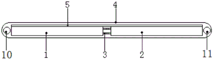
In the related art, as shown in fig. 1-1, a running board assembly includes: the front running board 1, the rear running board 2 with the front end surface hinged with the rear end surface of the front running board 1 through the hinging piece 3, and the annular running belt 4 which is sleeved on the front running board 1 and the rear running board 2 in a clearance manner. Wherein, the hinge joint of the front running board 1 and the rear running board 2 is provided with a hinge joint so that the rear running board 2 can be folded above the front running board 1. As shown in fig. 1-1, in normal use, the front running board 1 and the rear running board 2 are tiled and unfolded to form an integral running board; when folding is desired, the rear deck 2 is folded over the front deck 1 along the hinge 3, while the portion of the endless running belt 4 opposite the rear deck 2 is folded accordingly, as shown in fig. 1-2.
Since the front deck 1 and the rear deck 2 generally have a hinge joint therebetween in the related art, comfort is poor when a user moves on the endless running belt 4 above the hinge joint. To solve this technical problem, the embodiments of the present disclosure provide a running board assembly, by paving a flexible layer 5 on the upper surfaces of a front running board 1 and a rear running board 2, and covering a hinge joint, not only can smooth a "pit" formed by the hinge joint. And, based on the flexible characteristics of the flexible layer 5, the folding and unfolding of the front running board 1 and the rear running board 2 are not affected. By the arrangement, on one hand, the pit formed by the hinge joint is smoothed, and the discomfort of the sole of the user when the annular running belt 4 above the hinge joint moves is avoided. On the other hand, the flexible layer 5 also allows to reduce the impact vibrations between the annular running belt 4 and the front running plate 1 and the rear running plate 2, which further improves the user's movement experience on the running plate assembly.
In addition, even if there is a drop between the front running plate 1 and the rear running plate 2, by laying the flexible layer 5 thereon, it is also possible to smooth the drop, improving the comfort of the user when running.
It can be appreciated that the running board assembly provided in the embodiments of the present disclosure, in normal use, the front running board 1 and the rear running board 2 are tiled and spread to form an integral running board; when folding is required, the rear running board 2 is folded onto the front running board 1 along the hinge 3 (or the front running board 1 is folded onto the rear running board 2 along the hinge 3), while the part of the endless running belt 4 and the flexible layer 5 opposite to the rear running board 2 are also folded accordingly.
In one possible implementation, the flexible layer 5 is laid on part or all of the upper surfaces of the front deck 1 and the rear deck 2. The laying area of the flexible layer 5 is not particularly limited, and it is sufficient that the flexible layer 5 covers the hinge joint, so that a user can comfortably move on the endless running belt 4 above the hinge joint.
For example, the flexible layer 5 may have a lay area less than the sum of the upper surface areas of the front deck 1 and the rear deck 2.
By way of example, the laying area of the flexible layer 5 may be equal to the sum of the upper surface areas of the front and rear running boards 1, 2 and the upper surface area of the hinge joint.
By way of example, the lay area of the flexible layer 5 may be greater than the sum of the upper surface areas of the front and rear running boards 1, 2 and the upper surface area of the hinge joint, and the flexible layer 5 does not affect the folding, unfolding, and use of the running board assembly provided by the examples of the present disclosure.
The flexible layer 5 can be laid on the upper surfaces of the front running board 1 and the rear running board 2 in various ways, and on the premise of being easy to set and high in connection strength, the following gives an example illustration:
in one possible implementation: the flexible layer 5 is laid on the upper surfaces of the front running board 1 and the rear running board 2 in a bonding mode. The bonding mode is convenient for the flexible layer 5 made of different materials to be fixedly connected with the front running board 1 and the rear running board 2, and the operation is simple.
Illustratively, the flexible layer 5 may be bonded to the upper surfaces of the front deck 1 and the rear deck 2 by a strong adhesive. Wherein, the strong glue can be 3M strong glue.
In order to enhance the adhesion between the flexible layer 5 and the front running plate 1 and the rear running plate 2, a rough structure may be provided on the adhesion surfaces of the flexible layer 5, the front running plate 1 and the rear running plate 2 to improve the adhesion strength with the strong adhesive layer. The rough structure can be a groove with a round, square, triangle, other regular or irregular structure for containing strong glue, so that more strong glue can be contained between the flexible layer 5 and the front running plate 1 and the rear running plate 2, and the connection strength between the flexible layer 5 and the front running plate 1 and the rear running plate 2 is further enhanced.
Illustratively, the flexible layer 5 may also be adhered to the upper surfaces of the front and rear running boards 1, 2 by means of velcro. The sticking buckle bonding mode not only can ensure that the flexible layer 5 is in fastening connection with the front running plate 1 and the rear running plate 2, but also is convenient for the disassembly and assembly between the flexible layer 5 and the front running plate 1 and the rear running plate 2.
The velcro can be nylon velcro, and comprises nylon hook strips and nylon velvet strips. Wherein, can set up on the lower surface of the flexible layer 5, for example bond nylon hook tape, can set up on the upper surface of the front running board 1 and back running board 2, for example bond nylon nap tape, through making nylon hook tape and nylon nap tape bond, make the flexible layer 5 bond and spread on the upper surface of front running board 1 and back running board 2.
In another possible implementation: the flexible layer 5 is laid on the upper surfaces of the front running board 1 and the rear running board 2 in a clamping manner. The mode of joint not only can ensure to connect the fastening between flexible layer 5 and preceding running board 1 and back running board 2, and makes things convenient for the dismouting between flexible layer 5 and preceding running board 1 and the back running board 2.
For example, a plurality of male fasteners or female fasteners may be disposed on the lower surface of the flexible layer 5, and a plurality of female fasteners or male fasteners may be disposed on the upper surface of the front running board 1 and the upper surface of the rear running board 2, so that the connection between the flexible layer 5 and the front running board 1 and the rear running board 2 may be achieved by adapting the male fasteners and the female fasteners. When the flexible layer 5 needs to be disassembled, the flexible layer is lifted upwards with force.
Or, a plurality of clamping blocks can be arranged on the lower surface of the flexible layer 5, and a plurality of clamping grooves matched with the clamping blocks are arranged on the upper surface of the front running plate 1 and the upper surface of the rear running plate 2, so that the connection between the flexible layer 5 and the front running plate 1 and the rear running plate 2 can be realized by enabling the clamping blocks to be in clamping connection with the clamping grooves. When the flexible layer 5 needs to be disassembled, the flexible layer is lifted upwards with force.
The thickness of the flexible layer 5 may be set according to the specific application scenario, and in one possible implementation, the thickness of the flexible layer 5 may be 0.8mm to 1.2mm, for example, 0.8mm, 0.9mm, 1.0mm, 1.1mm, 1.2mm, etc. The thickness of the flexible layer 5 is set in this way, and on the premise of improving the comfort level of the user during running, the problem that the sole touch feeling of the user is poor due to excessive softness of the flexible layer 5 is avoided.
The flexible layer 5 may be made of a variety of materials having excellent flexibility and plasticity, and in one possible implementation, the flexible layer 5 is made of ethylene-vinyl acetate copolymer or polyethylene.
The flexible layer 5 is prepared from ethylene-vinyl acetate copolymer (EVA) to give excellent properties such as water resistance, corrosion resistance, plasticity, workability, vibration resistance, sound insulation, etc. to the flexible layer 5. The flexible layer 5 is prepared from Polyethylene (PE), which imparts excellent properties such as water resistance, corrosion resistance, and plasticity to the flexible layer 5. And EVA and PE are low in price and easy to obtain.
In order to avoid wearing the flexible layer 5 during the transmission of the endless running belt 4, in one possible implementation, as shown in fig. 2-2, the running board assembly provided in the embodiment of the present disclosure further includes: a wear-resistant layer 6; the wear-resistant layer 6 is laid on the upper surface of the flexible layer 5.
It will be appreciated that the wear layer 6 should have good plasticity without affecting the folding and unfolding of the deck assembly provided by the embodiments of the present disclosure.
The wear-resistant layer 6 can be laid on the upper surface of the flexible layer 5 in various ways, and on the premise of being easy to set and high in connection strength, an example is given below:
in one possible implementation: the wear-resistant layer 6 is laid on the upper surface of the flexible layer 5 by means of bonding. The bonding mode is convenient for the wearing layer 6 made of different materials to be fastened and connected with the flexible layer 5, and the operation is simple.
The wear layer 6 is, for example, glued to the upper surface of the flexible layer 5 by means of a strong glue.
The wear layer 6 is, for example, glued to the upper surface of the flexible layer 5 by means of a gluing.
The manner of setting the strong adhesive or the sticking buckle can be referred to the above description of the flexible layer 5, and will not be repeated here.
In another possible implementation: the wear-resistant layer 6 is paved on the upper surface of the flexible layer 5 in a clamping manner. The clamping mode not only can ensure the connection and the fastening between the wear-resistant layer 6 and the flexible layer 5, but also is convenient for the disassembly and the assembly between the wear-resistant layer 6 and the flexible layer 5.
For example, a plurality of male fasteners or female fasteners may be disposed on the lower surface of the wear-resistant layer 6, and a plurality of female fasteners or male fasteners may be disposed on the upper surface of the flexible layer 5, so that the connection between the flexible layer 5 and the wear-resistant layer 6 may be achieved by adapting the male fasteners to the female fasteners. When the wear-resistant layer 6 needs to be disassembled, the wear-resistant layer is lifted up with force.
By way of example, a plurality of clamping blocks can be arranged on the lower surface of the wear-resistant layer 6, and a plurality of clamping grooves matched with the clamping blocks are arranged on the upper surface of the flexible layer 5, so that the connection between the wear-resistant layer 6 and the flexible layer 5 can be realized by enabling the clamping blocks to be in clamping fit with the clamping grooves. When the wear-resistant layer 6 needs to be disassembled, the wear-resistant layer is lifted up with force.
The thickness of the wear layer 6 may be set according to the specific application scenario, and in one possible implementation, the thickness of the wear layer 6 may be 0.3-0.5 mm, for example, 0.3mm, 0.4mm, 0.5mm, etc. The thickness of the wear-resistant layer 6 is set so that the user can feel good in sole touch and comfortably experience running on the premise that the flexible layer 5 is prevented from being worn, and the thickness of the wear-resistant layer is matched with the thickness of the flexible layer 5.
The wear layer 6 may be made of a variety of materials having properties such as wear resistance, plasticity, etc., and in one possible implementation the wear layer 6 is made of polytetrafluoroethylene, nylon, or polyethylene terephthalate.
The wear-resistant layer 6 is prepared from polytetrafluoroethylene (Poly tetra fluoroethylene, PTFE) and can endow the wear-resistant layer 6 with excellent performances such as corrosion resistance, high lubrication non-tackiness, electrical insulation, high temperature resistance, wear resistance and the like. Wherein, polytetrafluoroethylene is also called teflon or Teflon.
The wear-resistant layer 6 is prepared by nylon (Polyamide, PA), and excellent tensile strength, impact strength, rigidity, wear resistance, chemical corrosion resistance and other excellent performances of the wear-resistant layer 6 can be endowed. Wherein nylon is also called polyamide fiber.
The wear-resistant layer 6 is prepared from polyethylene terephthalate (Polyethylene terephthalate, PET), and excellent creep resistance, fatigue resistance, friction resistance and dimensional stability can be provided for the wear-resistant layer 6. Furthermore, PTFE, PA, PET is inexpensive and easy to obtain.
In order to avoid noise generated between the wear-resistant layer 6 and the annular running belt 4 due to sliding friction, and ensure that the annular running belt 4 can be more smoothly driven, as shown in fig. 2-3, the running board assembly provided in the embodiment of the disclosure further includes: a smoothing layer 7; the smoothing layer 7 is laid on the upper surface of the wear-resistant layer 6.
It can be understood that the friction coefficient of the smooth layer 7 is adapted to the friction coefficient of the annular running belt 4, so that noise generated by sliding friction between the wear-resistant layer 6 and the annular running belt 4 can be avoided, and the annular running belt 4 can be ensured to be driven more smoothly. In addition, the user can move on the endless running belt 4 without slipping.
The smoothing layer 7 may be laid on the upper surface of the wear-resistant layer 6 in various ways, and on the premise of being easy to set and high in connection strength, an example is given below:
in one possible implementation: the smoothing layer 7 is laid on the wear-resistant layer 6 by means of bonding. The bonding mode is convenient for the smooth layer 7 and the wear-resistant layer 6 which are made of different materials to be firmly connected, and the operation is simple. For a specific arrangement thereof reference is made to the description of the flexible layer 5.
In another possible implementation: the smoothing layer 7 may be applied to the upper surface of the wear layer 6 by spraying. The spraying mode facilitates the connection and the fastening between the smooth layer 7 and the wear-resistant layer 6 made of different materials, and the operation is simple.
The smoothing layer 7 may be made of a variety of materials having a coefficient of friction less than that of the wear layer 6, and in one possible implementation the smoothing layer 7 is made of a rubber material doped with graphite. By setting the material of the smoothing layer 7 in this way, the smoothing layer 7 has a small friction coefficient and the sole touch feeling of the user during running exercise is good.
In order to avoid the flexible layers 5 on both sides of the hinge joint from being separated from the front running board 1 or the rear running board 2 to form a bulge when the running board assembly provided in the embodiments of the present disclosure is folded or unfolded, in one possible implementation, as shown in fig. 2 to 4, the running board assembly provided in the embodiments of the present disclosure further includes: a first fastening member 8 for fastening the connection of the flexible layers 5 on both sides of the hinge joint to the front running plate 1 and the rear running plate 2, respectively.
The first fastener 8 may be provided in a variety of forms, and on the premise of easy provision, several examples are given below:
the first fastener 8 is illustratively a strong glue layer; and the strong adhesive layers are respectively adhered between the flexible layer 5 and the front running board 1 and between the flexible layer 5 and the rear running board 2 at two sides of the hinge joint, see fig. 2-4.
Wherein, the strong adhesive layer can be a 3M strong adhesive layer.
It will be appreciated that when the flexible layer 5 is adhesively applied to the upper surfaces of the front deck 1 and the rear deck 2, the first fastener 8 is a layer of strong adhesive of greater thickness.
In order to further improve the connection strength between the flexible layer 5 and the front running plate 1 and the rear running plate 2, a rough structure can be arranged on the lower surface of the flexible layer 5 at two sides of the hinge joint and the upper surfaces of the front running plate 1 and the rear running plate 2, so that when the strong adhesive layer is bonded between the two rough structures, a first fastener 8 with stronger bonding strength can be formed.
The dimensions of the strong adhesive layers on both sides of the hinge joint can be set according to specific application scenarios, and in one possible implementation manner, the total length of the strong adhesive layers on both sides of the hinge joint along the front-back direction is 1-2 cm, for example, 1cm, 1.2cm, 1.4cm, 1.6cm, 1.8cm, 2cm, etc.; the thickness is 0.1 to 0.2mm, and may be, for example, 0.1mm, 0.12mm, 0.14mm, 0.16mm, 0.18mm, 0.2mm, etc.
It should be noted that, the total length of the strong adhesive layer along the front-back direction refers to: the length of the strong adhesive layer adhered to the front running board 1 along the front-back direction, the length of the hinge joint along the front-back direction and the length of the strong adhesive layer adhered to the rear running board 2 along the front-back direction are all the same.
The size of the powerful glue film of hinge joint both sides has been set up so, has strengthened the joint strength between preceding running board 1 and the flexible layer 5 of hinge joint both sides, between back running board 2 and the flexible layer 5, when avoiding folding or expanding the running board subassembly that this disclosed embodiment provided, flexible layer 5 breaks away from with preceding running board 1, back running board 2.
The first fastener 8 is exemplified by a plurality of rivets; and a plurality of rivets rivet the flexible layer 5 with the front running plate 1 and the flexible layer 5 with the rear running plate 2 respectively at both sides of the hinge joint. The riveting not only can make the flexible layer 5 of hinge joint both sides connect the fastening between preceding running board 1 and the back running board 2, and convenient operation, easy dismounting.
The rivet may be a flexible rivet or a non-flexible rivet, for example, when the flexible rivet is used, the flexible rivet may be made of the same material as the flexible layer 5, so as to avoid discomfort felt by a user when the user moves on the annular running belt 4.
When the non-flexible rivet is adopted, in order to avoid affecting the comfort level of a user during running, a plurality of counter bores can be arranged on the flexible layers 5 at two sides of the hinge joint, so that the head of the rivet is sunk below the surface of the flexible layers 5 after the rivet penetrates through the counter bores to rivet with the front running plate 1 or the rear running plate 2.
The first fastener 8 is illustratively a plurality of flexible fastener elements; and a plurality of flexible tightening pieces tighten the flexible layer 5 and the front running board 1, and the flexible layer 5 and the rear running board 2 respectively at two sides of the hinge joint. Can tighten between flexible layer 5 and preceding running board 1 and back running board 2 respectively of hinge joint both sides through a plurality of flexible tightening piece, convenient operation to, flexible tightening piece has flexibility, can not influence the comfort level of user when the motion on annular running belt 4.
Wherein, flexible tightening piece can be flexible tightening belt or flexible tightening ring, for example, when flexible tightening piece is flexible tightening belt, can twine flexible tightening belt respectively on being close to flexible layer 5 and preceding running board 1 of hinge joint to and flexible layer 5 and back running board 2, realize the flexible layer 5 of fastening hinge joint both sides respectively with preceding running board 1 and back running board 2 be connected.
When the flexible tightening piece is a flexible tightening ring, the flexible tightening piece is respectively sleeved on the flexible layer 5 and the front running plate 1 on two sides of the hinge joint, and the flexible layer 5 and the rear running plate 2, so that the flexible layer 5 on two sides of the hinge joint is respectively connected with the front running plate 1 and the rear running plate 2.
Further, in order to avoid the flexible layer 5 and the wear layer 6 at the hinge joint from being separated to form a bulge when folding or unfolding the running board assembly provided by the embodiments of the present disclosure, in one possible implementation, as shown in fig. 2-5, the running board assembly provided by the embodiments of the present disclosure further includes: a second fastening member 9 for fastening the connection between the flexible layer 5 and the wear layer 6 over the hinge joint.
The second fastening member 9 may be provided in various forms similar to the first fastening member 8, and the second fastening member 9 is a strong adhesive layer based on the ease of arrangement, see fig. 2-5.
It will be appreciated that the second fastener 9 is a strong glue layer of greater thickness when the wear layer 6 is adhesively applied to the flexible layer 5. The specific arrangement of the second fastening member 9 refers to the arrangement of the first fastening member 8 in the case of a strong adhesive layer, and will not be described herein.
The dimensions of the second fastening member 9 may be set according to the specific application, and in one possible implementation, the length of the second fastening member 9 in the front-rear direction is 1 to 2cm, for example, 1cm, 1.2cm, 1.4cm, 1.6cm, 1.8cm, 2cm, etc.; the thickness is 0.1 to 0.2mm, and may be, for example, 0.1mm, 0.12mm, 0.14mm, 0.16mm, 0.18mm, 0.2mm, etc. The second fastener 9 is dimensioned in such a way that the strength of the connection between the flexible layer 5 and the wear layer 6 is enhanced and matches the dimensions of the flexible layer 5 and the wear layer 6.
The rear end face of the front running plate 1 is hinged with the front end face of the rear running plate 2 through a hinge piece 3 so as to realize folding and unfolding of the front running plate 1 and the rear running plate 2. As an example, the hinge 3 comprises: the first connecting part, the pin shaft and the second connecting part; the front end of the first connecting part is connected with the rear end surface of the front running plate 1, and the rear end is provided with a first pin shaft hole; the rear end of the second connecting part is connected with the front end surface of the rear running plate 2, and the front end is provided with a second pin shaft hole; the pin shaft is rotatably arranged in the first pin shaft hole and the second pin shaft hole.
As shown in fig. 3, the running board assembly provided in the embodiment of the present disclosure further includes: a front drum 10, a rear drum 11, a bracket (not shown); the brackets are used for respectively providing support for the front running board 1, the rear running board 2, the front roller 10 and the rear roller 11; the front roller 10 is rotatably arranged in front of the front running plate 1, the rear roller 11 is rotatably arranged behind the rear running plate 2, the annular running belt 4 is sleeved on the front roller 10 and the rear roller 11 to drive around the front running plate 1 and the rear running plate 2, and meanwhile the front running plate 1 and the rear running plate 2 are accommodated in the annular running belt, so that the front running plate 1 and the rear running plate 2 can be sleeved in a transmission mode.
The diameters of the front roller 10 and the rear roller 11 are larger than the thicknesses of the front running plate 1 and the rear running plate 2, and in a default state, a gap is formed between the annular running belt 4 and the front running plate 1 and the rear running plate 2, that is, the annular running belt 4 is not completely attached to the front running plate 1 and the rear running plate 2. When in motion, the driving component can drive the front roller 10 to move, and the rear roller 11 is driven by the transmission of the endless running belt 4. It will be appreciated that at this point, when the user steps on the endless running belt 4, the endless running belt 4 is in direct contact with the wear layers 6 provided on the front running plate 1 and the rear running plate 2.
Embodiments of the present disclosure also provide a treadmill, the treadmill comprising: the running board assembly.
The running board assembly provided by the embodiment of the disclosure is applied to the running machine, and when the running machine is used, the running board assembly is unfolded, and the flexible layer 5 is arranged in the running board assembly, so that a user can experience movement comfortably. When accomodating the treadmill, with the folding of running board subassembly, reduced its area, conveniently accomodate.
In addition, due to the fact that the wear-resistant layer 6 is arranged in the running board assembly, the flexible layer 5 is prevented from being worn, and the service life of the flexible layer 5 is prolonged. The smooth layer 7 is paved on the upper surface of the wear-resistant layer 6, so that sliding friction force between the wear-resistant layer and the annular running belt 4 is reduced, noise generated by friction in the transmission process of the annular running belt 4 is avoided, the annular running belt 4 is conveniently and smoothly transmitted, and the movement experience of a user on the running machine is further improved.
As one example, the treadmill further comprises: a driving component for driving the running board component to move and a control component for controlling the driving component.
Specifically, the control component is used for controlling whether the driving component can work, the power output by the driving component and the like. The driving component is used for providing driving force for the front roller 10 and/or the rear roller 11 so that the front roller 10 and/or the rear roller 11 drive the endless running belt 4.
In one possible implementation, the driving assembly may simply provide driving force to the front roller 10 to rotate, and the rear roller 11 may be driven by the front roller 10 in cooperation with the endless running belt 4. The implementation mode is convenient for simplifying the structure of the running machine, ensures that the driving component and the control component are both centralized at the front part of the running machine, and is beneficial to reducing the energy consumption.
In one possible implementation, the control component includes: and a controller, in which a CPU (central processing unit ) is arranged to interpret and process the control command input by the user to the controller and send an action command to the driving component to control the driving component to work.
Illustratively, the drive assembly includes: and the motor is in transmission connection with the front roller 10 and is electrically connected with the controller. The controller controls the motor to work, and when the motor works, power is transmitted to the front roller 10 to rotate, so that the annular running belt 4 is driven to drive.
Other embodiments of the disclosure will be apparent to those skilled in the art from consideration of the specification and practice of the disclosure disclosed herein. This application is intended to cover any adaptations, uses, or adaptations of the disclosure following, in general, the principles of the disclosure and including such departures from the present disclosure as come within known or customary practice within the art to which the disclosure pertains. It is intended that the specification and examples be considered as exemplary only, with a true scope and spirit of the disclosure being indicated by the following claims.
It is to be understood that the present disclosure is not limited to the precise arrangements and instrumentalities shown in the drawings, and that various modifications and changes may be effected without departing from the scope thereof. The scope of the present disclosure is limited only by the appended claims.