EP2587838B1 - Hörgerätaufnahmezubehör - Google Patents
Hörgerätaufnahmezubehör Download PDFInfo
- Publication number
- EP2587838B1 EP2587838B1 EP11186420.3A EP11186420A EP2587838B1 EP 2587838 B1 EP2587838 B1 EP 2587838B1 EP 11186420 A EP11186420 A EP 11186420A EP 2587838 B1 EP2587838 B1 EP 2587838B1
- Authority
- EP
- European Patent Office
- Prior art keywords
- hearing aid
- connection means
- mechanical connection
- accessory
- face portion
- Prior art date
- Legal status (The legal status is an assumption and is not a legal conclusion. Google has not performed a legal analysis and makes no representation as to the accuracy of the status listed.)
- Not-in-force
Links
Images


Classifications
-
- H—ELECTRICITY
- H04—ELECTRIC COMMUNICATION TECHNIQUE
- H04R—LOUDSPEAKERS, MICROPHONES, GRAMOPHONE PICK-UPS OR LIKE ACOUSTIC ELECTROMECHANICAL TRANSDUCERS; DEAF-AID SETS; PUBLIC ADDRESS SYSTEMS
- H04R25/00—Deaf-aid sets, i.e. electro-acoustic or electro-mechanical hearing aids; Electric tinnitus maskers providing an auditory perception
- H04R25/65—Housing parts, e.g. shells, tips or moulds, or their manufacture
-
- H—ELECTRICITY
- H04—ELECTRIC COMMUNICATION TECHNIQUE
- H04R—LOUDSPEAKERS, MICROPHONES, GRAMOPHONE PICK-UPS OR LIKE ACOUSTIC ELECTROMECHANICAL TRANSDUCERS; DEAF-AID SETS; PUBLIC ADDRESS SYSTEMS
- H04R25/00—Deaf-aid sets, i.e. electro-acoustic or electro-mechanical hearing aids; Electric tinnitus maskers providing an auditory perception
- H04R25/60—Mounting or interconnection of hearing aid parts, e.g. inside tips, housings or to ossicles
- H04R25/607—Mounting or interconnection of hearing aid parts, e.g. inside tips, housings or to ossicles of earhooks
-
- H—ELECTRICITY
- H04—ELECTRIC COMMUNICATION TECHNIQUE
- H04R—LOUDSPEAKERS, MICROPHONES, GRAMOPHONE PICK-UPS OR LIKE ACOUSTIC ELECTROMECHANICAL TRANSDUCERS; DEAF-AID SETS; PUBLIC ADDRESS SYSTEMS
- H04R2225/00—Details of deaf aids covered by H04R25/00, not provided for in any of its subgroups
- H04R2225/021—Behind the ear [BTE] hearing aids
- H04R2225/0213—Constructional details of earhooks, e.g. shape, material
-
- H—ELECTRICITY
- H04—ELECTRIC COMMUNICATION TECHNIQUE
- H04R—LOUDSPEAKERS, MICROPHONES, GRAMOPHONE PICK-UPS OR LIKE ACOUSTIC ELECTROMECHANICAL TRANSDUCERS; DEAF-AID SETS; PUBLIC ADDRESS SYSTEMS
- H04R25/00—Deaf-aid sets, i.e. electro-acoustic or electro-mechanical hearing aids; Electric tinnitus maskers providing an auditory perception
- H04R25/60—Mounting or interconnection of hearing aid parts, e.g. inside tips, housings or to ossicles
- H04R25/602—Mounting or interconnection of hearing aid parts, e.g. inside tips, housings or to ossicles of batteries
-
- H—ELECTRICITY
- H04—ELECTRIC COMMUNICATION TECHNIQUE
- H04R—LOUDSPEAKERS, MICROPHONES, GRAMOPHONE PICK-UPS OR LIKE ACOUSTIC ELECTROMECHANICAL TRANSDUCERS; DEAF-AID SETS; PUBLIC ADDRESS SYSTEMS
- H04R25/00—Deaf-aid sets, i.e. electro-acoustic or electro-mechanical hearing aids; Electric tinnitus maskers providing an auditory perception
- H04R25/60—Mounting or interconnection of hearing aid parts, e.g. inside tips, housings or to ossicles
- H04R25/609—Mounting or interconnection of hearing aid parts, e.g. inside tips, housings or to ossicles of circuitry
Definitions
- the invention is related to a hearing aid retainer accessory for retaining a BTE (behind-the-ear) hearing aid at a user's ear.
- a BTE-hearing aid In order to operate at best and to prevent damage resulting from falling of the ear and dropping to the ground, a BTE-hearing aid has to be kept in a safe position at a user's ear. Also if the user's head moves intensely such as it may do by doing sport. Another example is a child playing.
- US 2007/0217641 A1 discloses a hearing aid protection accessory formed by a flexible sleeve to be wrapped around a housing of a hearing aid, the flexible sleeve to be connected to a users clothing via a clip and a cord. Suitable for preventing the hearing aid from dropping to the ground this arrangement, however, does not allow an adjustment to a user's ear and is likely to entangle with all kinds of obstacles a child may encounter playing. Also the sleeve adds to the thickness of the hearing aid housing rendering it difficult to be placed behind a small ear.
- US 4,881,616 and US 4,702,345 each disclose a hearing aid retainer accessory that is formed by a tube with a respective sleeve connected to each end, both sleeves pulled over the housing of the hearing aid.
- the arrangement disclosed in US 4,881,616 allows an adjustment to a user ear by moving the sleeves toward or away from each other on the housing of the hearing aid. The degree of adjustment, however, is limited by the longitudinal dimension of the hearing aid housing.
- the sleeves of both US 4,881,616 and US 4,702,345 add to the thickness of the hearing aid housing, resulting in a discomfort to wear or even the ears protruding, provided they are still in a process of growth. Furthermore, the sleeves are likely to interfere with a control button located at the surface of the hearing aid housing.
- US 7,013,018 B2 discloses an adjustable earring for a headset, the earring being connected via a pivotal link to a housing of a speaker included in the headset.
- US 4,918,757 and US 3,327,807 each disclose an arrangement for retaining a hearing aid at a user's head utilizing a head band. Undesirably each of the arrangements exerts an uncomfortable force to the users head and is rather noticeable.
- DE10048337 relates to a hearing aid device comprising a housing and a carrier hook for supporting the housing behind the ear.
- the opposite end of the housing to the carrier hook is provided with a fixed or releasable retaining element that cooperates with an otoplastic worn within the ear.
- the retaining element may incorporate an electrical cable and/or a sound channel.
- WO2004112431 concerns an electrical and mechanical connection between a head worn communication device and an accessory thereto.
- Mechanical connection means and electrical connection points at the communication device are placed at one and the same surface part, and further connection means and electrical connection points at the accessory are placed at one and the same surface part, such that a sliding action between the two surface parts will cause the respective mechanical connection means to grip each other while the respective electrical connection points gain contact with each other.
- the document further relates to a hearing aid with an accessory.
- WO2009083007 relates to a hearing instrument with a housing that is adapted for positioning in the ear canal of a user without obstructing the ear canal of the user.
- the housing accommodates a signal processor for generating an audio signal, and a receiver that is connected to an output of the signal processor for converting the processed compensated audio signal into a sound signal, wherein the housing has a trunk part that is interconnected with a tip part.
- the housing further accommodates a printed circuit board with the signal processor forming a wall within the housing extending transversely to the longitudinal extension of the trunk part.
- a hearing aid in the scope of the present invention is a BTE-hearing aid or a BTE-like-hearing aid.
- the technical object is achieved by a hearing aid retainer accessory according to the subject-matter of claim 1.
- the hearing aid retainer accessory is free of interference with a hearing aid's control buttons and the specially designed hearing aid geometry.
- the hearing aid retainer accessory is very intuitive and easy to attach to a hearing aid.
- the first mechanical connection means can be shaped as a hook-like protrusion.
- the hook-like protrusion can be fitted to a complementary cut-out region embodied by a mechanical connection terminal of a longitudinal end face portion of hearing aid's housing. When said first mechanical connection means is connected to said mechanical connection terminal, the hook-like protrusion is accommodated in the cut-out region, providing a very stable mechanical connection.
- first and the second end face portion comprise a respective first and second electrical connection means electrically connected to each other.
- the first electrical connection means is configured to engage an electrical connection point of a longitudinal end face portion of a hearing aid's housing.
- the second electrical connection means is configured to engage an electrical connector of accessory component's connector portion. In this way an electric/electronic accessory component like an FM-transmitter can be electrically connected to a hearing indirectly, once a hearing aid's electrical connection point is occupied by the first electrical connection means of the hearing aid retainer accessory.
- the first and/or second electrical connection means can be configured as connection points to allow a very reliable electrical connection.
- the first end face portion has a surface area of roughly the same size as a longitudinal end face portion of a hearing aid's housing.
- the first end face portion can have a surface area of roughly the same size as an accessory component's connector portion.
- the first and the second end face portion can have a surface area of roughly the same size.
- first and the second end face portion comprise a respective first and second electrical connection means electrically connected to each other.
- the first electrical connection means is configured to engage to an electrical connection point of a longitudinal end face portion of a hearing aid's housing.
- the second electrical connection means is engaged to an electrical connector comprised by the accessory component's connector portion.
- the first electrical connection means and the second electrical connection means can be provided as connection points.
- the first mechanical connection means and the mechanical connector can be identically shaped a as a hook-like protrusion fitted to a cut-out region embodying the second mechanical connection means.
- the first and the second end face portion can face away from each other.
- the first and the second end face portion can have a surface area of roughly the same size as the connector portion.
- the technical object is achieved by a hearing aid assembly according to the subject-matter of claim 11.
- the first and the second end face portion comprise a respective first and second electrical connection means electrically connected to each other.
- the first electrical connection means is engaged to the electrical connection point.
- the second electrical connection means is engaged to an electrical connector comprised by the accessory component's connector portion.
- the accessory component can thus be supplied with electrical energy/signals from the hearing aid or can supply electrical energy/signals to the hearing aid.
- the first electrical connection means and the second electrical connection means can be provided as connection points.
- the first mechanical connection means and the mechanical connector can be identically shaped a as a hook-like protrusion fitted to a cut-out region embodying the second mechanical connection means and the mechanical connection terminal. This provides for a sturdy mechanical connection throughout the hearing aid assembly.
- first and the second end face portion can face away from each other.
- the first and the second end face portion can have a surface area of roughly the same size as the connector portion and/or the longitudinal end face portion. This provides for the hearing aid's assembly to have a seamless outer surface and hence a high comfort in wear.
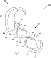
- Fig.1 shows a hearing aid 20, a hearing aid retainer accessory 10 and an accessory component 30.
- the hearing aid 20 is designed as a BTE hearing aid with a housing 21 having a longitudinal end face portion 22.
- the longitudinal end face portion 22 comprises a mechanical connection terminal 23 and an electrical connection point 24.
- the hearing aid retainer accessory 10 comprises a retainer element 11 with a firm hook-like shape.
- the retainer element 11 has a first end face portion 12 with a first mechanical connection means 13 having a hook-like protrusion being engageable to a mechanical connection terminal 23, which is designed as a cut-out region (to be seen best in fig. 2 ), of a longitudinal end face portion 22.
- the retainer element 11 comprises a second end face portion 16 having a second mechanical connection means 17 shaped as cut-out region complementary to the first mechanical connection means 13 (to be seen best in fig. 2 )
- the first mechanical connection means 13 and the mechanical connector 33 are identically shaped as a hook-like protrusion fitted to a cut-out region embodying the second mechanical connection means 17.
- said second mechanical connection means 17 is engageable to said mechanical connector 33, while also being connectable to the mechanical connection terminal 23.
- the first and the second end face portion 12, 16 comprise a respective first and second electrical connection means 14, 18 electrically connected to each other.
- the first electrical connection means 14 is configured as connection points to engage to an electrical connection point 24 of a longitudinal end face portion 22 of a hearing aid's 20 housing 21, the second electrical connection means 18 is configured as connection points being configured to engage to an electrical connector 34 of accessory component's 30 connector portion 32.
- the first and the second end face portion 12, 16 faces away from each other and have a surface area of roughly the same size. Furthermore, the first end face portion 12 has a surface area of roughly the same size as the longitudinal end face portion 22 of the hearing aid's 20 housing 21 and the same size as the accessory component's 30 connector portion 32.
- the accessory component 30 is connected to the hearing aid retainer accessory 10 by a sliding on motion (indicated by direction arrow next to the mechanical connector 33).
- the mechanical connector 33 is engaged to the second mechanical connection means 17 and the electrical connector 34 is connected to the second electrical connection means 18. Since the first and second electrical connection means 14, 18 are electrically connected to each other, and electrical connector 34 is connected to the second electrical connection means 18, the electrical connector 34 is also in electrical connection with the first electrical connection means 14.
- a hearing aid assembly 100 is modularly formed by connecting the hearing aid 10, the hearing aid retainer accessory 20 and the accessory component 30 by sliding said components onto each other (indicated by direction arrow next to the mechanical connector 33 and first mechanical connection means 13).
- a battery drawer 25 of the hearing aid 20 is in an open position.
- the first mechanical connection means 13 is engaged to the mechanical connection terminal 23 and the mechanical connector 33 is engaged to the second mechanical connection means 17.
- the first electrical connection means 14 is engaged to the electrical connection point 24 and the second electrical connection means 18 is engaged to the electrical connector 34 comprised by the accessory component's 30 connector portion 32.
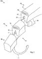
- Fig. 2 shows a perspective view of the arrangement of fig. 1 to especially provide a better understanding of the second mechanical connection means 17 and the mechanical connection terminal 23, both being configured as a cut-out region being complementary to the first mechanical connection means 13 and the mechanical connector 33 described with respect to fig. 1 .
- the connection point 24 is configured as connection points being placed on the same surface, namely the longitudinal end face portion 22, as the mechanical connection terminal 23.
- the second electrical connection means 18 are configured as connection points placed on the same surface, namely the second end face portion 15, as the second mechanical connection means 17.
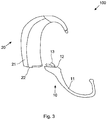
- a retainer element 11 with a firm and hook-like shape having a first end face portion 12 with a first mechanical connection means 13 configured as a hook-like protrusion to be engageable to a mechanical connection terminal 23, which is designed as a cut-out region (to be seen best in fig. 4 ) of a longitudinal end face portion 22 of a housing 21 of a hearing aid 20.
- the first end face portion 12 has a surface area of roughly the same size as the longitudinal end face portion 22 of the hearing aid's 20 housing 21.
- a hearing aid assembly 100 is modularly formed by connecting the hearing aid 20 and the hearing aid retainer accessory 10 sliding said components onto each other (indicated by direction arrow next to the first mechanical connection means 13).
- a battery drawer 25 of the hearing aid 20 is in an open position.
- the first mechanical connection means 13 is engaged to the mechanical connection terminal 23.
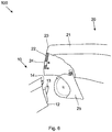
- Fig. 4 shows a perspective view of the arrangement of fig. 3 to especially provide a better understanding of the mechanical connection terminal 23 being configured as a cut-out region being complementary to the first mechanical connection means 13 described with respect to fig. 3
- the connection point 24 is configured as connection points being placed on the same surface, namely the longitudinal end face portion 22, as the mechanical connection terminal 23.
- FIG. 5 schematically depicts a detailed view representing both the first end face portion 12 of the hearing aid retainer accessory 10 from fig. 1 and fig. 2 and the connector portion 32 of the accessory component 30 from fig. 1 and fig. 2 likewise.
- the first end face portion 12 comprises a first mechanical connection means 13 configured as a hook-like protrusion placed on the same surface with a comprised first electrical connection means 14 configured as connection points.
- the connector portion 32 comprises a mechanical connector 33 configured as a hook-like protrusion placed on the same surface with a comprised an electrical connector 34 configured as connection points.
- a hearing aid retainer accessory 10 in fig. 7 comprises a retainer element 11 having a firm and hook-like shape and comprising a first end face portion 12 with first mechanical connection means 13 configured to be engageable to a mechanical connection terminal 23 of a longitudinal end face portion 22 of a housing 21 of a hearing aid 20.
- the first mechanical connection means 13 is shaped as a male euro-pin connector.
- the mechanical connection terminal 23 on the other hand is provided as a female euro-pin connector. Since only a mechanical connection between the hearing aid 20 and the aid retainer accessory 10 is required, the first mechanical connection means 13 is electrically nonconducting.
- a hearing aid assembly 100 is modularly formed by mechanically connecting the hearing aid 10 and the hearing aid retainer accessory 20 pushing said components onto each other.
- the male euro-pin connector protruding from first end face portion 12 is engaged with the female euro-pin connector located in the longitudinal end face portion 22.
- the first end face portion 12 has a surface area of roughly the same size as the longitudinal end face portion 22 of the hearing aid's 20 housing 21.
Claims (14)
- Hörgeräthaltezubehör (10) zur Verwendung mit einem Hörgerät (20), das ein Gehäuse (21) mit einem Längs-Stirnendabschnitt (22) hat, der einen mechanischen Verbindungsanschluss (23) und einen elektrischen Verbindungspunkt (24) aufweist, wobei das Hörgeräthaltezubehör (10) ein Halteelement (11) mit einem ersten Stirnendabschnitt (12) aufweist, der ein erstes mechanisches Verbindungsmittel (13) hat, das konfiguriert ist in einen mechanischen Verbindungsanschluss (23) des Längs-Stirnendabschnitts (22) des Gehäuses (21) des Hörgerätes (20) einzugreifen,
wobei das Haltemittel (11) einen zweiten Stirnendabschnitt (16) aufweist, der ein zweites mechanisches Verbindungsmittel (17) hat, das konfiguriert ist, in einen mechanischen Verbinder (33) eines Verbindungsabschnitts (32) einer Zubehörkomponente (30) einzugreifen, dadurch gekennzeichnet, dass das zweite mechanische Verbindungsmittel (17) als Ausnehmung geformt ist, die zu dem ersten mechanischen Verbindungsmittel (13) komplementär ist, so dass die Ausnehmung angepasst ist, zu dem mechanischen Verbinder (33) zu passen, der als hakenartiger Vorsprung geformt ist. - Hörgeräthaltezubehör (10) gemäß Anspruch 1, dadurch gekennzeichnet, dass das erste mechanische Verbindungsmittel (13) als hakenartiger Vorsprung geformt ist, der ausgebildet ist zu einer den mechanischen Verbindungsanschluss (23) des Längsstirnendes (22) des Gehäuses (21) des Hörgeräts (20) verkörpernden Ausnehmung zu passen.
- Hörgeräthaltezubehör (10) gemäß Anspruch 1, dadurch gekennzeichnet dass die ersten und zweiten Stirnendabschnitte (12, 16) entsprechende erste und zweite elektrische Verbindungsmittel (14, 18) aufweisen, die elektrisch miteinander verbunden sind, wobei das erste elektrische Verbindungsmittel (14) dazu konfiguriert ist, in den elektrischen Verbindungspunkt (24) des Längs- Stirnendabschnitts (22) des Gehäuses (21) des Hörgeräts (20) einzugreifen, wobei das zweite elektrische Verbindungsmittel (18) dazu konfiguriert ist, in einen elektrischen Anschluss (34) des Verbindungsabschnitts (32) der Zubehörkomponente (30) einzugreifen.
- Hörgeräthaltezubehör (10) gemäß einem der Ansprüche 1 bis 3, dadurch gekennzeichnet, dass der erste Stirnendabschnitt (12) eine Oberflächen-Fläche hat, die dieselbe Größe hat, wie der Längs-Stirnendabschnitt (22) des Gehäuses (21) des Hörgerätes (20).
- Hörgeräthaltezubehör (10) gemäß einem der Ansprüche 1 bis 4, dadurch gekennzeichnet, dass der erste Stirnendabschnitt (12) eine Oberflächen-Fläche hat, die dieselbe Größe hat, wie der Verbindungsabschnitt (32) der Zubehörkomponente (30).
- Hörgeräthaltezubehör (10) gemäß einem der Ansprüche 3 bis 4, dadurch gekennzeichnet, dass die ersten und zweiten Stirnendabschnitte (12, 16) von einander abgewandt sind und eine Oberflächen-Fläche von gleicher Größe haben.
- Hörgerätzubehöreinheit (40), die modular gebildet ist
von einem Hörgeräthaltezubehör (10), das ein erstes Halteelement (11) mit ersten und zweiten Stirnendabschnitten (12, 16) aufweist, die entsprechende erste und zweite mechanische Verbindungsmittel (13, 17) haben, wobei das erste mechanische Verbindungsmittel (13) konfiguriert ist, in einen mechanischen Verbindungsanschluss (23) eines Längs-Stirnendabschnitts (22) einzugreifen, der einen elektrischen Verbindungspunkt (24) eines Gehäuses (21) eines Gehörgerätes (20) aufweist und
von einer Zubehörkomponente (30), die einen Verbindungsabschnitt (32) mit einem mechanischen Verbinder (33) hat, der dazu konfiguriert ist, in das zweite mechanische Verbindungsmittel (17) einzugreifen, dadurch gekennzeichnet, dass das zweite mechanische Verbindungsmittel (17) als Ausnehmung geformt ist, die komplementär zu dem ersten mechanischen Verbindungsmittel (13) ist, so dass die Ausnehmung angepasst ist, zu dem mechanischen Verbinder (33) zu passen, der als hakenartiger Vorsprung geformt ist. - Hörgerätezubehöreinheit (40) gemäß Anspruch 7, dadurch gekennzeichnet, dass die ersten und zweiten Stirnendabschnitte (12, 16) entsprechende erste und zweite elektrische Verbindungsmittel (14, 18) aufweisen, die miteinander elektrisch verbunden sind, wobei das erste elektrische Verbindungsmittel (14) dazu konfiguriert ist, in den elektrischen Verbindungspunkt (24) des Längs-Stirnendabschnitts (22) des Gehäuses (21) des Hörgerätes (20) einzugreifen und das zweite elektrische Verbindungsmittel (18) das dazu konfiguriert ist, in einen elektrischen Anschluss (34) einzugreifen, den der Verbindungsabschnitt (32) der Zubehörkomponente (30) aufweist.
- Hörgerätzubehöreinheit (40) gemäß Anspruch 7 oder 8, dadurch gekennzeichnet, dass das erste mechanische Verbindungsmittel (13) als hakenartiger Vorsprung geformt ist, der angepasst ist zu einer Ausnehmung zu passen, die den zweiten mechanischen Verbindungsanschluss (23) verkörpert.
- Hörgerätzubehöreinheit (40) gemäß einem der Ansprüche 7 bis 9, dadurch gekennzeichnet, dass die ersten und zweiten Stirnendabschnitte (12, 16) von einander abgewandt sind und eine Oberflächen-Fläche mit derselben Größe haben wie der Verbindungsabschnitt (32) und der Längs-Stirnendabschnitt (22).
- Hörgerätanordnung (100) die modular gebildet ist
von einem Hörgerät (20) das ein Gehäuse (21) mit einem Längs-Stirnendabschnitt (22) hat, welcher einen mechanischen Verbindungsanschluss (23) und einen elektrischen Verbindungspunkt (24) aufweist,
von einem Hörgeräthaltezubehör (10), das ein Halteelement (11) mit einem ersten und einem zweiten Stirnendabschnitt (12, 16) aufweist, die erste und zweite mechanische Verbindungsmittel (13, 17) haben, wobei das erste mechanische Verbindungsmittel (13) dazu konfiguriert ist, in dem mechanischen Verbindungsanschluss (23) einzugreifen und
und von einer Zubehörkomponente (30), die einen Verbindungsabschnitt (32) mit einem mechanischen Verbinder (33) hat, der dazu konfiguriert ist, in das zweite mechanische Verbindungsmittel (17) einzugreifen, dadurch gekennzeichnet,
dass das zweite mechanische Verbindungsmittel (17) als Ausnehmung geformt ist, die komplementär zu dem ersten mechanischen Verbindungsmittel (13) ist, so dass die Ausnehmung angepasst ist, zu dem mechanischen Verbinder (33) zu passen, der als hakenartiger Vorsprung geformt ist. - Hörgeräteanordnung (100) gemäß Anspruch 11, dadurch gekennzeichnet, dass die ersten und zweiten Stirnendabschnitte (12, 16) entsprechende erste und zweite elektrische Verbindungsmittel (14, 18) aufweisen, die elektrisch miteinander verbunden sind, wobei das erste elektrische Verbindungsmittel (14) dazu konfiguriert ist, in den elektrischen Verbindungspunkt (24) einzugreifen und das zweite elektrische Verbindungsmittel (18) konfiguriert ist, in einen elektrischen Anschluss (34) einzugreifen, den der Verbindungsabschnitt (32) der Zubehörkomponente (30) aufweist.
- Hörgerätanordnung (100) gemäß Anspruch 11 oder 12, dadurch gekennzeichnet, dass das erste mechanische Verbindungsmittel (13) als hakenartiger Vorsprung geformt ist, der angepasst ist, zu einer Ausnehmung zu passen, die den mechanischen Verbindungsanschluss (23) verkörpert.
- Hörgerätanordnung (100) gemäß einem der Ansprüche 11 bis 13, dadurch gekennzeichnet, dass die ersten und zweiten Stirnendabschnitte (12, 16) voneinander abgewandt sind und eine Oberflächen-Fläche mit derselben Größe haben, wie der Verbindungsabschnitt (32) und der Längs-Stirnendabschnitt (22).
Priority Applications (5)
| Application Number | Priority Date | Filing Date | Title |
|---|---|---|---|
| EP11186420.3A EP2587838B1 (de) | 2011-10-25 | 2011-10-25 | Hörgerätaufnahmezubehör |
| DK11186420.3T DK2587838T3 (en) | 2011-10-25 | 2011-10-25 | Hearing Holder Accessories |
| US13/659,525 US8848958B2 (en) | 2011-10-25 | 2012-10-24 | Hearing aid retainer accessory |
| AU2012244208A AU2012244208A1 (en) | 2011-10-25 | 2012-10-25 | A Hearing Aid Retainer Accessory |
| CN201210412962.9A CN103124391B (zh) | 2011-10-25 | 2012-10-25 | 助听器保持配件 |
Applications Claiming Priority (1)
| Application Number | Priority Date | Filing Date | Title |
|---|---|---|---|
| EP11186420.3A EP2587838B1 (de) | 2011-10-25 | 2011-10-25 | Hörgerätaufnahmezubehör |
Publications (2)
| Publication Number | Publication Date |
|---|---|
| EP2587838A1 EP2587838A1 (de) | 2013-05-01 |
| EP2587838B1 true EP2587838B1 (de) | 2018-03-07 |
Family
ID=45217174
Family Applications (1)
| Application Number | Title | Priority Date | Filing Date |
|---|---|---|---|
| EP11186420.3A Not-in-force EP2587838B1 (de) | 2011-10-25 | 2011-10-25 | Hörgerätaufnahmezubehör |
Country Status (5)
| Country | Link |
|---|---|
| US (1) | US8848958B2 (de) |
| EP (1) | EP2587838B1 (de) |
| CN (1) | CN103124391B (de) |
| AU (1) | AU2012244208A1 (de) |
| DK (1) | DK2587838T3 (de) |
Families Citing this family (8)
| Publication number | Priority date | Publication date | Assignee | Title |
|---|---|---|---|---|
| EP3226582A1 (de) * | 2016-03-29 | 2017-10-04 | Oticon Medical A/S | Hörgerät mit modularem verbindungsmittel |
| DK3469815T3 (da) * | 2016-06-10 | 2020-02-10 | Sivantos Pte Ltd | Elektronikramme til understøtning af elektroniske komponenter i et høreapparat, høreapparat og kit til et høreapparat |
| AU2018203536B2 (en) * | 2017-05-23 | 2022-06-30 | Oticon Medical A/S | Hearing Aid Device Unit Along a Single Curved Axis |
| US10674282B2 (en) * | 2017-07-18 | 2020-06-02 | Cochlear Limited | Safety ear hook apparatus |
| US10659859B2 (en) | 2018-02-28 | 2020-05-19 | Starkey Laboratories, Inc. | Portable case for modular hearing assistance devices |
| US11716580B2 (en) | 2018-02-28 | 2023-08-01 | Starkey Laboratories, Inc. | Health monitoring with ear-wearable devices and accessory devices |
| US10939216B2 (en) | 2018-02-28 | 2021-03-02 | Starkey Laboratories, Inc. | Health monitoring with ear-wearable devices and accessory devices |
| US10911878B2 (en) | 2018-12-21 | 2021-02-02 | Starkey Laboratories, Inc. | Modularization of components of an ear-wearable device |
Family Cites Families (19)
| Publication number | Priority date | Publication date | Assignee | Title |
|---|---|---|---|---|
| US3327807A (en) | 1966-12-13 | 1967-06-27 | Textron Inc | Hearing aid apparatus |
| US4702345A (en) | 1986-07-21 | 1987-10-27 | Janssen Gwen V | Hearing aid retention device |
| US4918757A (en) | 1989-01-30 | 1990-04-24 | Janssen Gwen V | Hearing aid headband support |
| US4881616A (en) | 1989-04-07 | 1989-11-21 | Janssen Gwen V | Hearing aid retention apparatus |
| US6748094B1 (en) | 2000-03-03 | 2004-06-08 | Advanced Bionics Corporation | Connector system for BTE hearing devices |
| DE10048337C1 (de) * | 2000-09-29 | 2002-03-07 | Siemens Audiologische Technik | Hinter dem Ohr tragbares Hörhilfegerät |
| DK174403B1 (da) | 2001-01-04 | 2003-02-10 | Gn Netcom As | Ørering til hovedsæt |
| US7142926B2 (en) | 2002-08-30 | 2006-11-28 | Advanced Bionics Corporation | Quick connect earhook system for BTE devices |
| WO2004080123A1 (en) * | 2003-03-06 | 2004-09-16 | Widex A/S | Method of connecting an accessory to a hearing aid and the combination of an adapter and an accessory |
| EP1637011B1 (de) * | 2003-06-13 | 2016-09-28 | Oticon A/S | Elektrischer und mechanischer anschluss zwischen getragener kommunikation hauptvorrichtung und zusatzgerät dazu |
| US20070217641A1 (en) | 2006-03-15 | 2007-09-20 | Rosal Mark B | Ear Gear |
| DE102006029958A1 (de) * | 2006-06-29 | 2008-01-03 | Siemens Audiologische Technik Gmbh | Modulares Hinter-dem-Ohr-Hörgerät |
| EP1988744A1 (de) | 2007-04-30 | 2008-11-05 | Siemens Medical Instruments Pte. Ltd. | Verbindungselement für einen Tragehaken eines Hörgeräts |
| DE102007025936B4 (de) | 2007-06-04 | 2010-01-21 | Siemens Medical Instruments Pte. Ltd. | Hörgerät mit am Gehäuserahmen befestigtem Anschlussstück |
| US20110135131A1 (en) | 2007-10-16 | 2011-06-09 | Estron A/S | Flexible connector for hearing device |
| DE102007054325A1 (de) * | 2007-11-14 | 2009-05-28 | Siemens Medical Instruments Pte. Ltd. | Hörhilfegerät |
| JP6144865B2 (ja) * | 2007-12-27 | 2017-06-07 | ジーエヌ リザウンド エー/エスGn Resound A/S | プリント回路基板で形成された壁を有する聴覚補助装置 |
| US8023674B2 (en) * | 2008-09-17 | 2011-09-20 | Daniel R. Schumaier | Connector for hearing assistance device having reduced mechanical feedback |
| US8442252B2 (en) * | 2010-09-30 | 2013-05-14 | Audiotoniq, Inc. | Behind-the-ear hearing aid with interchangeable ear hook and ear tube |
-
2011
- 2011-10-25 DK DK11186420.3T patent/DK2587838T3/en active
- 2011-10-25 EP EP11186420.3A patent/EP2587838B1/de not_active Not-in-force
-
2012
- 2012-10-24 US US13/659,525 patent/US8848958B2/en active Active
- 2012-10-25 AU AU2012244208A patent/AU2012244208A1/en not_active Abandoned
- 2012-10-25 CN CN201210412962.9A patent/CN103124391B/zh not_active Expired - Fee Related
Non-Patent Citations (1)
| Title |
|---|
| None * |
Also Published As
| Publication number | Publication date |
|---|---|
| US8848958B2 (en) | 2014-09-30 |
| DK2587838T3 (en) | 2018-05-28 |
| CN103124391A (zh) | 2013-05-29 |
| AU2012244208A1 (en) | 2013-05-09 |
| US20130294627A1 (en) | 2013-11-07 |
| EP2587838A1 (de) | 2013-05-01 |
| CN103124391B (zh) | 2017-09-08 |
Similar Documents
| Publication | Publication Date | Title |
|---|---|---|
| EP2587838B1 (de) | Hörgerätaufnahmezubehör | |
| US9949014B2 (en) | Wireless pair of earbuds | |
| US9826302B2 (en) | Electronic device with magnetically stowable speaker assemblies | |
| US7123737B2 (en) | Ear clasp headset | |
| US20150350762A1 (en) | Monaural wireless headset | |
| EP2628315B1 (de) | Kommunikations-headset | |
| EP2894875B1 (de) | Kopfhörer | |
| US9462369B2 (en) | Ambient and audio earphone system | |
| WO2011077160A1 (en) | Earphone | |
| JP2008048247A (ja) | ヘッドセット | |
| DK2645744T3 (en) | Hearing instrument with flexible earplug tube connection | |
| US8953828B2 (en) | Hearing aid retainer accessory | |
| EP2587839B1 (de) | Hörgerätaufnahmezubehör | |
| US20220369017A1 (en) | Sound output device | |
| US8498436B2 (en) | Hearing device with a conducting element, in particular a sound tube | |
| US8355519B2 (en) | Tool for fitting and removing a receiver of a hearing aid | |
| US20160165332A1 (en) | Headset | |
| US8023678B2 (en) | Hearing device with on/off switch and associated method | |
| JP2006222840A (ja) | イヤホン、イヤホン本体及びイヤホンケーブル | |
| WO2011059375A1 (en) | Ear attachment | |
| WO2010059123A1 (en) | Hearing aid | |
| GB2385738A (en) | Head-mounted microphone transmitting signals to a hearing aid |
Legal Events
| Date | Code | Title | Description |
|---|---|---|---|
| PUAI | Public reference made under article 153(3) epc to a published international application that has entered the european phase |
Free format text: ORIGINAL CODE: 0009012 |
|
| AK | Designated contracting states |
Kind code of ref document: A1 Designated state(s): AL AT BE BG CH CY CZ DE DK EE ES FI FR GB GR HR HU IE IS IT LI LT LU LV MC MK MT NL NO PL PT RO RS SE SI SK SM TR |
|
| AX | Request for extension of the european patent |
Extension state: BA ME |
|
| 17P | Request for examination filed |
Effective date: 20131104 |
|
| RBV | Designated contracting states (corrected) |
Designated state(s): AL AT BE BG CH CY CZ DE DK EE ES FI FR GB GR HR HU IE IS IT LI LT LU LV MC MK MT NL NO PL PT RO RS SE SI SK SM TR |
|
| 17Q | First examination report despatched |
Effective date: 20161214 |
|
| GRAP | Despatch of communication of intention to grant a patent |
Free format text: ORIGINAL CODE: EPIDOSNIGR1 |
|
| INTG | Intention to grant announced |
Effective date: 20170921 |
|
| GRAS | Grant fee paid |
Free format text: ORIGINAL CODE: EPIDOSNIGR3 |
|
| GRAA | (expected) grant |
Free format text: ORIGINAL CODE: 0009210 |
|
| AK | Designated contracting states |
Kind code of ref document: B1 Designated state(s): AL AT BE BG CH CY CZ DE DK EE ES FI FR GB GR HR HU IE IS IT LI LT LU LV MC MK MT NL NO PL PT RO RS SE SI SK SM TR |
|
| REG | Reference to a national code |
Ref country code: GB Ref legal event code: FG4D |
|
| REG | Reference to a national code |
Ref country code: CH Ref legal event code: EP Ref country code: AT Ref legal event code: REF Ref document number: 977803 Country of ref document: AT Kind code of ref document: T Effective date: 20180315 |
|
| REG | Reference to a national code |
Ref country code: IE Ref legal event code: FG4D |
|
| REG | Reference to a national code |
Ref country code: DE Ref legal event code: R096 Ref document number: 602011046219 Country of ref document: DE |
|
| REG | Reference to a national code |
Ref country code: DK Ref legal event code: T3 Effective date: 20180522 |
|
| REG | Reference to a national code |
Ref country code: NL Ref legal event code: MP Effective date: 20180307 |
|
| REG | Reference to a national code |
Ref country code: LT Ref legal event code: MG4D |
|
| PG25 | Lapsed in a contracting state [announced via postgrant information from national office to epo] |
Ref country code: LT Free format text: LAPSE BECAUSE OF FAILURE TO SUBMIT A TRANSLATION OF THE DESCRIPTION OR TO PAY THE FEE WITHIN THE PRESCRIBED TIME-LIMIT Effective date: 20180307 Ref country code: CY Free format text: LAPSE BECAUSE OF FAILURE TO SUBMIT A TRANSLATION OF THE DESCRIPTION OR TO PAY THE FEE WITHIN THE PRESCRIBED TIME-LIMIT Effective date: 20180307 Ref country code: FI Free format text: LAPSE BECAUSE OF FAILURE TO SUBMIT A TRANSLATION OF THE DESCRIPTION OR TO PAY THE FEE WITHIN THE PRESCRIBED TIME-LIMIT Effective date: 20180307 Ref country code: NO Free format text: LAPSE BECAUSE OF FAILURE TO SUBMIT A TRANSLATION OF THE DESCRIPTION OR TO PAY THE FEE WITHIN THE PRESCRIBED TIME-LIMIT Effective date: 20180607 Ref country code: ES Free format text: LAPSE BECAUSE OF FAILURE TO SUBMIT A TRANSLATION OF THE DESCRIPTION OR TO PAY THE FEE WITHIN THE PRESCRIBED TIME-LIMIT Effective date: 20180307 Ref country code: HR Free format text: LAPSE BECAUSE OF FAILURE TO SUBMIT A TRANSLATION OF THE DESCRIPTION OR TO PAY THE FEE WITHIN THE PRESCRIBED TIME-LIMIT Effective date: 20180307 |
|
| REG | Reference to a national code |
Ref country code: AT Ref legal event code: MK05 Ref document number: 977803 Country of ref document: AT Kind code of ref document: T Effective date: 20180307 |
|
| PG25 | Lapsed in a contracting state [announced via postgrant information from national office to epo] |
Ref country code: RS Free format text: LAPSE BECAUSE OF FAILURE TO SUBMIT A TRANSLATION OF THE DESCRIPTION OR TO PAY THE FEE WITHIN THE PRESCRIBED TIME-LIMIT Effective date: 20180307 Ref country code: SE Free format text: LAPSE BECAUSE OF FAILURE TO SUBMIT A TRANSLATION OF THE DESCRIPTION OR TO PAY THE FEE WITHIN THE PRESCRIBED TIME-LIMIT Effective date: 20180307 Ref country code: LV Free format text: LAPSE BECAUSE OF FAILURE TO SUBMIT A TRANSLATION OF THE DESCRIPTION OR TO PAY THE FEE WITHIN THE PRESCRIBED TIME-LIMIT Effective date: 20180307 Ref country code: BG Free format text: LAPSE BECAUSE OF FAILURE TO SUBMIT A TRANSLATION OF THE DESCRIPTION OR TO PAY THE FEE WITHIN THE PRESCRIBED TIME-LIMIT Effective date: 20180607 Ref country code: GR Free format text: LAPSE BECAUSE OF FAILURE TO SUBMIT A TRANSLATION OF THE DESCRIPTION OR TO PAY THE FEE WITHIN THE PRESCRIBED TIME-LIMIT Effective date: 20180608 |
|
| REG | Reference to a national code |
Ref country code: FR Ref legal event code: PLFP Year of fee payment: 8 |
|
| PG25 | Lapsed in a contracting state [announced via postgrant information from national office to epo] |
Ref country code: EE Free format text: LAPSE BECAUSE OF FAILURE TO SUBMIT A TRANSLATION OF THE DESCRIPTION OR TO PAY THE FEE WITHIN THE PRESCRIBED TIME-LIMIT Effective date: 20180307 Ref country code: RO Free format text: LAPSE BECAUSE OF FAILURE TO SUBMIT A TRANSLATION OF THE DESCRIPTION OR TO PAY THE FEE WITHIN THE PRESCRIBED TIME-LIMIT Effective date: 20180307 Ref country code: NL Free format text: LAPSE BECAUSE OF FAILURE TO SUBMIT A TRANSLATION OF THE DESCRIPTION OR TO PAY THE FEE WITHIN THE PRESCRIBED TIME-LIMIT Effective date: 20180307 Ref country code: IT Free format text: LAPSE BECAUSE OF FAILURE TO SUBMIT A TRANSLATION OF THE DESCRIPTION OR TO PAY THE FEE WITHIN THE PRESCRIBED TIME-LIMIT Effective date: 20180307 Ref country code: PL Free format text: LAPSE BECAUSE OF FAILURE TO SUBMIT A TRANSLATION OF THE DESCRIPTION OR TO PAY THE FEE WITHIN THE PRESCRIBED TIME-LIMIT Effective date: 20180307 Ref country code: AL Free format text: LAPSE BECAUSE OF FAILURE TO SUBMIT A TRANSLATION OF THE DESCRIPTION OR TO PAY THE FEE WITHIN THE PRESCRIBED TIME-LIMIT Effective date: 20180307 |
|
| PG25 | Lapsed in a contracting state [announced via postgrant information from national office to epo] |
Ref country code: SK Free format text: LAPSE BECAUSE OF FAILURE TO SUBMIT A TRANSLATION OF THE DESCRIPTION OR TO PAY THE FEE WITHIN THE PRESCRIBED TIME-LIMIT Effective date: 20180307 Ref country code: SM Free format text: LAPSE BECAUSE OF FAILURE TO SUBMIT A TRANSLATION OF THE DESCRIPTION OR TO PAY THE FEE WITHIN THE PRESCRIBED TIME-LIMIT Effective date: 20180307 Ref country code: AT Free format text: LAPSE BECAUSE OF FAILURE TO SUBMIT A TRANSLATION OF THE DESCRIPTION OR TO PAY THE FEE WITHIN THE PRESCRIBED TIME-LIMIT Effective date: 20180307 Ref country code: CZ Free format text: LAPSE BECAUSE OF FAILURE TO SUBMIT A TRANSLATION OF THE DESCRIPTION OR TO PAY THE FEE WITHIN THE PRESCRIBED TIME-LIMIT Effective date: 20180307 |
|
| REG | Reference to a national code |
Ref country code: DE Ref legal event code: R097 Ref document number: 602011046219 Country of ref document: DE |
|
| PG25 | Lapsed in a contracting state [announced via postgrant information from national office to epo] |
Ref country code: PT Free format text: LAPSE BECAUSE OF FAILURE TO SUBMIT A TRANSLATION OF THE DESCRIPTION OR TO PAY THE FEE WITHIN THE PRESCRIBED TIME-LIMIT Effective date: 20180709 |
|
| PLBE | No opposition filed within time limit |
Free format text: ORIGINAL CODE: 0009261 |
|
| STAA | Information on the status of an ep patent application or granted ep patent |
Free format text: STATUS: NO OPPOSITION FILED WITHIN TIME LIMIT |
|
| 26N | No opposition filed |
Effective date: 20181210 |
|
| PG25 | Lapsed in a contracting state [announced via postgrant information from national office to epo] |
Ref country code: SI Free format text: LAPSE BECAUSE OF FAILURE TO SUBMIT A TRANSLATION OF THE DESCRIPTION OR TO PAY THE FEE WITHIN THE PRESCRIBED TIME-LIMIT Effective date: 20180307 |
|
| REG | Reference to a national code |
Ref country code: BE Ref legal event code: MM Effective date: 20181031 |
|
| PG25 | Lapsed in a contracting state [announced via postgrant information from national office to epo] |
Ref country code: MC Free format text: LAPSE BECAUSE OF FAILURE TO SUBMIT A TRANSLATION OF THE DESCRIPTION OR TO PAY THE FEE WITHIN THE PRESCRIBED TIME-LIMIT Effective date: 20180307 Ref country code: LU Free format text: LAPSE BECAUSE OF NON-PAYMENT OF DUE FEES Effective date: 20181025 |
|
| REG | Reference to a national code |
Ref country code: IE Ref legal event code: MM4A |
|
| PG25 | Lapsed in a contracting state [announced via postgrant information from national office to epo] |
Ref country code: BE Free format text: LAPSE BECAUSE OF NON-PAYMENT OF DUE FEES Effective date: 20181031 |
|
| PG25 | Lapsed in a contracting state [announced via postgrant information from national office to epo] |
Ref country code: IE Free format text: LAPSE BECAUSE OF NON-PAYMENT OF DUE FEES Effective date: 20181025 |
|
| PG25 | Lapsed in a contracting state [announced via postgrant information from national office to epo] |
Ref country code: MT Free format text: LAPSE BECAUSE OF NON-PAYMENT OF DUE FEES Effective date: 20181025 |
|
| PG25 | Lapsed in a contracting state [announced via postgrant information from national office to epo] |
Ref country code: TR Free format text: LAPSE BECAUSE OF FAILURE TO SUBMIT A TRANSLATION OF THE DESCRIPTION OR TO PAY THE FEE WITHIN THE PRESCRIBED TIME-LIMIT Effective date: 20180307 |
|
| PG25 | Lapsed in a contracting state [announced via postgrant information from national office to epo] |
Ref country code: HU Free format text: LAPSE BECAUSE OF FAILURE TO SUBMIT A TRANSLATION OF THE DESCRIPTION OR TO PAY THE FEE WITHIN THE PRESCRIBED TIME-LIMIT; INVALID AB INITIO Effective date: 20111025 Ref country code: MK Free format text: LAPSE BECAUSE OF NON-PAYMENT OF DUE FEES Effective date: 20180307 |
|
| PG25 | Lapsed in a contracting state [announced via postgrant information from national office to epo] |
Ref country code: IS Free format text: LAPSE BECAUSE OF FAILURE TO SUBMIT A TRANSLATION OF THE DESCRIPTION OR TO PAY THE FEE WITHIN THE PRESCRIBED TIME-LIMIT Effective date: 20180707 |
|
| PGFP | Annual fee paid to national office [announced via postgrant information from national office to epo] |
Ref country code: DK Payment date: 20211004 Year of fee payment: 11 Ref country code: GB Payment date: 20211004 Year of fee payment: 11 Ref country code: DE Payment date: 20211005 Year of fee payment: 11 |
|
| PGFP | Annual fee paid to national office [announced via postgrant information from national office to epo] |
Ref country code: FR Payment date: 20211004 Year of fee payment: 11 Ref country code: CH Payment date: 20211007 Year of fee payment: 11 |
|
| REG | Reference to a national code |
Ref country code: DE Ref legal event code: R119 Ref document number: 602011046219 Country of ref document: DE |
|
| REG | Reference to a national code |
Ref country code: DK Ref legal event code: EBP Effective date: 20221031 |
|
| REG | Reference to a national code |
Ref country code: CH Ref legal event code: PL |
|
| GBPC | Gb: european patent ceased through non-payment of renewal fee |
Effective date: 20221025 |
|
| PG25 | Lapsed in a contracting state [announced via postgrant information from national office to epo] |
Ref country code: LI Free format text: LAPSE BECAUSE OF NON-PAYMENT OF DUE FEES Effective date: 20221031 Ref country code: FR Free format text: LAPSE BECAUSE OF NON-PAYMENT OF DUE FEES Effective date: 20221031 Ref country code: DE Free format text: LAPSE BECAUSE OF NON-PAYMENT OF DUE FEES Effective date: 20230503 Ref country code: CH Free format text: LAPSE BECAUSE OF NON-PAYMENT OF DUE FEES Effective date: 20221031 |
|
| PG25 | Lapsed in a contracting state [announced via postgrant information from national office to epo] |
Ref country code: GB Free format text: LAPSE BECAUSE OF NON-PAYMENT OF DUE FEES Effective date: 20221025 Ref country code: DK Free format text: LAPSE BECAUSE OF NON-PAYMENT OF DUE FEES Effective date: 20221031 |