EP2587605A2 - Limiteurs de surtension de courant actif avec détecteur de tension et relais - Google Patents
Limiteurs de surtension de courant actif avec détecteur de tension et relais Download PDFInfo
- Publication number
- EP2587605A2 EP2587605A2 EP13150511.7A EP13150511A EP2587605A2 EP 2587605 A2 EP2587605 A2 EP 2587605A2 EP 13150511 A EP13150511 A EP 13150511A EP 2587605 A2 EP2587605 A2 EP 2587605A2
- Authority
- EP
- European Patent Office
- Prior art keywords
- power supply
- relay
- current
- voltage
- disturbance
- Prior art date
- Legal status (The legal status is an assumption and is not a legal conclusion. Google has not performed a legal analysis and makes no representation as to the accuracy of the status listed.)
- Withdrawn
Links
Images

Classifications
-
- H—ELECTRICITY
- H02—GENERATION; CONVERSION OR DISTRIBUTION OF ELECTRIC POWER
- H02J—CIRCUIT ARRANGEMENTS OR SYSTEMS FOR SUPPLYING OR DISTRIBUTING ELECTRIC POWER; SYSTEMS FOR STORING ELECTRIC ENERGY
- H02J3/00—Circuit arrangements for ac mains or ac distribution networks
- H02J3/18—Arrangements for adjusting, eliminating or compensating reactive power in networks
- H02J3/1807—Arrangements for adjusting, eliminating or compensating reactive power in networks using series compensators
-
- H—ELECTRICITY
- H02—GENERATION; CONVERSION OR DISTRIBUTION OF ELECTRIC POWER
- H02H—EMERGENCY PROTECTIVE CIRCUIT ARRANGEMENTS
- H02H9/00—Emergency protective circuit arrangements for limiting excess current or voltage without disconnection
- H02H9/02—Emergency protective circuit arrangements for limiting excess current or voltage without disconnection responsive to excess current
-
- Y—GENERAL TAGGING OF NEW TECHNOLOGICAL DEVELOPMENTS; GENERAL TAGGING OF CROSS-SECTIONAL TECHNOLOGIES SPANNING OVER SEVERAL SECTIONS OF THE IPC; TECHNICAL SUBJECTS COVERED BY FORMER USPC CROSS-REFERENCE ART COLLECTIONS [XRACs] AND DIGESTS
- Y02—TECHNOLOGIES OR APPLICATIONS FOR MITIGATION OR ADAPTATION AGAINST CLIMATE CHANGE
- Y02E—REDUCTION OF GREENHOUSE GAS [GHG] EMISSIONS, RELATED TO ENERGY GENERATION, TRANSMISSION OR DISTRIBUTION
- Y02E40/00—Technologies for an efficient electrical power generation, transmission or distribution
- Y02E40/30—Reactive power compensation
Definitions
- the present disclosure is generally related to limiting current surge and, more particularly, embodiments of the present disclosure are related to actively limiting surge current produced by power supply disturbances during load operation.
- Inrush current limiting circuits including a negative temperature coefficient (NTC) thermistor or resistor connected between a power supply and a protected load and a bypass switch in parallel with the NTC thermistor, are often used to mitigate the current surge seen by the load during starting.
- NTC thermistor is a component with a resistance that decreases as its temperature increases. During startup, the temperature of the NTC thermistor is cold and its resistance is high. As operation continues, the temperature increases and the resistance of the NTC thermistor decreases, allowing more current during normal operation.
- the bypass switch closes to remove the resistor from between the power supply and the electrical load.
- the current limiter circuit remains disabled until the equipment is de-energized and the bypass switch is reopened. While the inrush current limiter circuits limit the current surge during startup, these inrush current limiter circuits do not provide protection from electrical transients during normal operation of the electrical equipment.
- embodiments of this disclosure include active current surge limiters and methods of use.
- One exemplary system comprises a current limiter, including an interface configured to be connected between a power supply and a load; a disturbance sensor, configured to monitor the power supply for a disturbance during operation of the load; and an activator, configured to receive a control signal from the disturbance sensor and to activate the current limiter based on the control signal.
- the power supply may be an alternating current (AC) power supply.
- AC alternating current
- a circuit breaker may be tripped to de-energize the load when the disturbance continues beyond a preset period.
- the current limiter may include at least one of the group consisting of: a resistor, an NTC thermistor, and a varistor.
- the disturbance sensor may monitor at least one of the group consisting of: voltage, current, and combinations thereof.
- the disturbance may be a voltage sag.
- the disturbance may also be a current surge.
- a current limit may be preset. The current limit may be determined by the disturbance sensor. The current limit may be based on starting current of the load.
- the activator may include a bypass circuit.
- the bypass circuit may include at least one of the group consisting of: an electromechanical relay, a semiconductor switch, a triac, a thyristor.
- the current limiter may be activated while the disturbance detected.
- Another exemplary system comprises means for limiting current supplied to a load from a power supply; means for sensing a disturbance on the power supply during operation of the load; and means for activating the means for limiting current to the load when a disturbance is sensed.
- the system may further include means for de-energizing the load when the disturbance exceeds a preset period.
- One exemplary method comprises monitoring a condition of a power supply during operation of a load connected to the power supply; determining if the condition falls outside of an acceptable limit; and activating a current limiting device when the monitored condition falls outside of acceptable limits.
- the monitored condition may include voltage, current, and combinations thereof.
- the acceptable limit may be determined based on variations of the monitored condition during operation of the load.
- the current limiting device may be deactivated when the monitored condition falls within acceptable limits.
- the current limiting device may be deactivated after a preset period of time.
- Voltage sags have been shown to occur fairly frequently in industrial settings. Studies indicate that voltage sags are 100 to a 1000 times more likely to occur than voltage surges. Data and analysis strongly suggest a high probability that operating equipment will be damaged by a current surge that occurs at the end of the voltage sag. The most vulnerable point for typical equipment is the end of short-duration sags, when the inrush limiting circuits are normally disabled. The current surge can have excessively high I2T ratings because the normal inrush limiting circuit (NTC thermistor or resistor + bypass switch) is disabled. The current surge causes damage to equipment, as well as degradation of components leading to shortened equipment life and premature equipment failure. Industrial, commercial and residential equipment that are potentially subject to the problem include, but are not limited to, PC's, servers, TV's, stereo amplifiers, microwave ovens, PLC's, robots, machine drives, medical equipment, etc.
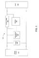
- Fig. 1 illustrates an active current surge limiter.
- the active current surge limiter 100 is connected at an interface between a power supply 110 and a load 120.
- Power supplies include AC and/or DC sources. While the principles discussed are generally applied to applications up to 1000 Volts, this does not prevent their use in applications at higher voltage levels. Loads that are sensitive to these disturbances include, but are not limited to, industrial, commercial and residential equipment that include power electron components.
- a transient voltage surge suppressor (TVSS) 130 connected on the input side can provide the added functionality of a voltage surge suppressor device.
- TVSS transient voltage surge suppressor
- the active current surge limiter 100 includes a current limiter 140 for limiting the current supplied to the connected load 120, a disturbance sensor 150 for monitoring the condition of the power supply 110, and an activator 160 for activating the current limiter 140 when the disturbance sensor detects a disturbance on the power supply.
- Disturbances in the power supply can include variations in the power supply characteristics such as, but are not limited to, the voltage, current, and combinations thereof.
- the presence of a power supply disturbance is indicated when the sensed characteristic falls outside established operational limits.
- Operational limits can be preset based on variables such as, but not limited to, industrial standards and known load and supply characteristics. However, as the power supply and load characteristics are typically unknown, establishment of allowable current limits can require additional analysis.
- Another alternative is to allow the disturbance sensor 150 to establish limits based on continuous monitoring of selected supply characteristics.
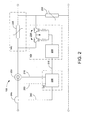
- Fig. 2 is an alternative embodiment of the active current surge limiter utilizing a microcontroller and semiconductor switches.
- This non-limiting embodiment of an active current surge limiter 100, the disturbance sensor 150 uses a microprocessor or microcontroller 200 to establish allowable current limits, continuously monitor power supply characteristics (i.e. sensing voltage 205 and current 210), and communicate a control signal 215 to the activator 160 indicating the presence of a disturbance on the power supply.
- the described control strategy allows the active current surge limiter 100 to handle power-up and load change without problems.
- the circuit in Fig. 2 senses and measures the current 210 drawn by the load 120, including peak current at start-up, through a current transformer 220.
- the peak current at start-up is stored in a peak-rectifier circuit (not shown), including a diode and capacitor coupled with a current transformer, and measured by an A/D converter incorporated in the microcontroller 200.
- a peak-rectifier circuit not shown
- the starting current is recorded and stored by the microcontroller 200 as a peak inrush current.
- the microcontroller 200 continues to monitor the load current 210 and record any sensed peak currents.
- the microcontroller 200 also monitors the incoming ac line voltage 205. Limits for the sensed voltage 205 can be preset or established by the microcontroller 200. Voltage sags occur when a supply voltage drops below 90% of rated voltage for short periods of time of one half cycle or more. When a sag in the monitored line voltage 205 is detected by the microcontroller 200, a peak current limit reference (Imax) is set to the maximum peak current value thus far recorded. During the voltage sag, the current drawn by the load is most likely to decrease. At the end of the voltage sag, the voltage quickly returns to normal, causing a surge in the sensed current 210.
- Imax peak current limit reference
- the magnitude of the surge current is affected by load factors, such as the type, condition, and proximity as well as power supply factors, such as duration of disturbance, line impedance, and transformer location.
- load factors such as the type, condition, and proximity
- power supply factors such as duration of disturbance, line impedance, and transformer location.
- Industrial, commercial and residential equipment vulnerable to the effects of current surges include, but not limited to, PC's, servers, TV's, stereo amplifiers, microwave ovens, PLC's, robots, machine drives, and medical equipment.
- any equipment utilizing rectifier/capacitor circuits amplify the surge current effects when the capacitor is substantially discharged during a voltage sag.
- a control signal 215 is sent to the activator 160 indicating the presence of a disturbance.
- the current limiter 140 is activated by turning off a semiconductor switch 225 through a gate drive 230. Activation of the current limiter 140 forces the load current to flow through an ac voltage clamping device 235, such as but not limited to, a varistor. The voltage impressed across the load 120 is reduced, limiting the current supplied to the load. The switch 225 can then be turned on at, but not limited to, the next cycle, a zero crossing point, and a predetermined number of switching under a high frequency duty cycle control scheme as is customary in PWM circuits.
- a trip signal 240 is activated by the microcontroller 200, opening an overload switch or circuit breaker 245 and shutting the system down until a reset is effectuated, e.g., a reset button is pressed.
- Incorporation of a voltage clamping device 250 provides additional voltage surge protection to the connected load 120.
- gate turn-off devices 225 allows turn-off and over-current protection even under normal voltage conditions as well as in the presence of fast rising current fronts that occur under fault conditions.
- the components are sized to handle trapped energy in line and load inductances.
- power dissipation during continuous operation should be considered during selection.
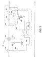
- Fig. 3 is an alternative embodiment of the active current surge limiter utilizing a microcontroller and an electromechanical relay.
- This non-limiting embodiment utilizes the same disturbance sensor 150 to sense voltage 205 and current 210 as depicted in Fig. 2 .
- the current limiter 140 can be bypassed using an electromechanical relay, contactor or switch.
- a control signal 215 sent by the microcontroller 200 causes a normally-open relay 355 to close and deactivate the current limiter 140.
- the power supply is continuously monitored as described for Fig. 2 .
- Fast detection algorithms allow the detection of supply disturbances within one quarter to one half cycle.
- Fast detection algorithms can be implemented in, but not limited to, software, hardware and/or individual components. Because the line current drawn by the load typically drops dramatically when the DC capacitor reverse biases the diode bridge during a voltage sag, a voltage sag that is likely to cause inrush current can be can readily detected.
- the control signal 215 Upon detecting the onset of the voltage sag, the control signal 215 causes the relay 355 to open and activating the current limiter 140.
- the current limiter 140 in this embodiment includes two resistors, 360 and 365, with a thyristor pair or triac 370 connected in parallel with the second resistor 365. Alternative combinations can also be utilized. Upon exceeding Imax, resistors 360 and 365 provide a high resistance to limit current to the attached load. After a sufficient time delay or a determination that the sensed current 210 is below an allowable level, the triac 370 is turned on, allowing higher current levels. Control of the triac 370 is provided by a signal 375 sent by the microcontroller 200 to a gate driver 330 for the triac 370.
- the relay 355 is reclosed allowing normal load operation to resume. As described for Fig. 2 , if the sensed current 210 remains high for a predetermined period, a trip signal 240 is activated by the microcontroller 200, opening an overload switch or circuit breaker 245 and shutting the system down.
- the level of surge current that flows in the system depends on a number of parameters including, but not limited to, the depth and duration of the voltage sag, the load rating, the short circuit current available at the load point, and the amount of capacitance in the load rectifier.
- Monitoring of Imax provides an indication of the load characteristics and maximum current necessary for normal operation.
- the current flowing through the resistors 360 and 365 forward biases the diode and provides an indication of the effective DC bus voltage (Vdc) in the load.
- triac 370 If triac 370 is turned on at an angle ⁇ , the difference between the line and DC bus voltages (Vline - Vdc) is applied across resistor 360 and allowing an increase in current flow to the load 120. Neglecting line and load inductances, the line current decreases until, at an angle ⁇ , it reaches to zero when the line voltage equals Vdc. By controlling the turn-on of triac 370, it is possible to control the average current supplied to the load capacitance and minimize recovery time. As Vdc increases with capacitor charging, ⁇ automatically changes to keep the line current limited and under control. Once the current drawn by load has returned to within allowable limits, the relay 355 can be closed again, allowing normal operation to resume.
- This embodiment can also provide a soft start process for equipment without built-in startup protection.
- a two stage soft start process is initiated.
- resistors 360 and 365 provide a high resistance to limit inrush current.
- triac 370 is turned on to allow higher current levels.
- the relay 355 is closed allowing normal load operation to begin.
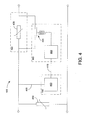
- Fig. 4 is an alternative embodiment of the active current surge limiter utilizing a voltage detector and an electromechanical relay.
- a normally-open relay 455 is used to activate the current limiter 140 which includes a resistor or Negative Temperature Coefficient (NTC) thermistor 435.
- NTC thermistor 435 has a high resistance value when cold. The resistance drops dramatically as the NTC thermistor 435 heat up, often by a factor of 10 or more, allowing higher currents to flow. The high resistance returns as the NTC thermistor 435 cools off. Manufacturers typically specify cooling times of up to 60 seconds or more.
- the relay 455 is maintained off (open) and the NTC thermistor 435 limits the inrush current that flows. As current flows, the resistance of the NTC thermistor 435 decreases providing less current limitation. After a preset time delay, the relay 455 is turned on to de-energize the current limiter 140 by bypassing the NTC thermistor 435. This allows the NTC thermistor 435 to cool down and restore the high resistance mode.
- a detector circuit 400 is implemented that identifies when a voltage sag occurs, and send a control signal 415 to activate the current limiter 140.
- One of many possible implementations of the detector circuit 400 utilizes a microprocessor with an A/D converter to sense and measure the line voltage 405. The microprocessor identifies when the voltage falls outside a nominally acceptable boundary defined by a preset limit.
- the detector circuit 400 sends a control signal 415 to a timer circuit 480 which causes the relay 455 to close and activate the current limiter 140.
- the resistance of the NTC thermistor 435 decreases until a preset time is reached.
- the timer circuit 480 de-energizes the relay 455 bypassing the NTC thermistor 435. Incorporation of a voltage clamping device 450 provides additional voltage surge protection to both the connected load 120 and the active current surge limiter 100.
- Fig. 5 is an alternative embodiment of the active current surge limiter utilizing an optocoupler and an electromechanical relay.
- This non-limiting embodiment uses a circuit for simulating the operation of a DC power supply in the disturbance sensor.
- the diode bridge 501 and the capacitor 502 represent a typical rectifier/capacitor circuit that may be used in a load 120.
- the inductance 503 and resistance 504 simulate effective line impedance.
- the time constant of the load resistor 506 and capacitor 502 is chosen to be similar to that found in rectifier/capacitor circuits.
- This circuit simulates the operation of a high power rectifier/capacitor circuit at low cost.
- the capacitor 502 is charged from the line at the peaks of the sensed line voltage 505, as the simulated load would.
- An optocoupler 507 is used to detect the charging current pulse at the line voltage peaks and send a control signal 515 to the activator 160.
- a retriggerable monostable multi-vibrator 590 with an output pulse greater than one half cycle (8.33 mS) is triggered by the control signal 515 from the optocoupler 507. As long as the charging current pulses occur every half cycle, the monostable multi-vibrator 590 remains triggered.
- the output of the monostable multi-vibrator 590 is used to close the relay 555 through a semiconductor switch 595, such as but not limited to, a transistor. While the line voltage is within specified limits, the relay 555 is maintained closed, de-energizing the current limiter 140 by bypassing a current limiting device 535, such as but not limited to, an NTC thermistor, triac, and resistor.
- the charging current pulses stop, causing the optocoupler 507 to stop sending triggering pulses as the control signal 515.
- monostable multi-vibrator 590 output changes state at the end of the timing period, causing switch 595 to turn the relay off. This then reinserts the current limiting device 535 into the circuit limiting the inrush current to the load 120. Then the AC line voltage returns to normal, the charging current pulses begin again and the monostable multi-vibrator 590 is retriggered once again. After waiting for a preset time, the relay 555 is closed once again, de-energizing the current limiter 140.
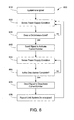
- Fig. 6 is a flow chart illustrating an embodiment of a fast detection algorithm 600 for the active current surge limiter.
- Fast detection algorithms 600 can be implemented in, but not limited to, software, hardware and/or individual components, as illustrated in the previous embodiments of Fig. 2-5 .
- the active current surge limiter 100 is energized 610 upon starting the connected load 120.
- the active current surge limiter 100 begins sensing the power supply conditions 620. This can include, but is not limited to, voltage, current, and combinations thereof.
- the sensed conditions are then evaluated to determine if a disturbance exists 630. If it is determined that no disturbance exists, then the active current surge limiter 100 continues to sense 620 and evaluate 630 the power supply condition. If a disturbance does exist, then the current limiter 140 is activated 640.
- the active current surge limiter 100 returns sensing the power supply conditions 650. The sensed conditions are then evaluated to determine if the disturbance is complete 660. If it is determined that the disturbance still exists, then the active current surge limiter 100 continues to sense 650 and evaluate 660 the power supply condition. If the disturbance no longer exists, then the current limiter 140 is deactivated 670. The process repeats until the active current surge limiter 100 and its load 120 are de-energized.
Applications Claiming Priority (2)
| Application Number | Priority Date | Filing Date | Title |
|---|---|---|---|
| US64846605P | 2005-01-31 | 2005-01-31 | |
| EP05815446A EP1847001B1 (fr) | 2005-01-31 | 2005-10-24 | Limiteurs actifs de pic de courant |
Related Parent Applications (1)
| Application Number | Title | Priority Date | Filing Date |
|---|---|---|---|
| EP05815446.9 Division | 2005-10-24 |
Publications (1)
| Publication Number | Publication Date |
|---|---|
| EP2587605A2 true EP2587605A2 (fr) | 2013-05-01 |
Family
ID=36777547
Family Applications (6)
| Application Number | Title | Priority Date | Filing Date |
|---|---|---|---|
| EP05815446A Not-in-force EP1847001B1 (fr) | 2005-01-31 | 2005-10-24 | Limiteurs actifs de pic de courant |
| EP13150529.9A Withdrawn EP2587603A2 (fr) | 2005-01-31 | 2005-10-24 | Limiteurs de surtension de courant actif avec anticipation de courant d'appel |
| EP13150496.1A Withdrawn EP2587601A2 (fr) | 2005-01-31 | 2005-10-24 | Limiteurs de surtension de courant actif avec capteur de perturbation et limitation de courant à plusieurs étages |
| EP13150514.1A Withdrawn EP2587602A2 (fr) | 2005-01-31 | 2005-10-24 | Limiteurs de surtension de courant actif avec circuit de surveillance |
| EP13150511.7A Withdrawn EP2587605A2 (fr) | 2005-01-31 | 2005-10-24 | Limiteurs de surtension de courant actif avec détecteur de tension et relais |
| EP06719761A Not-in-force EP1851777B1 (fr) | 2005-01-31 | 2006-01-30 | Systemes et methodes de compensation serie distribuee de lignes d'alimentation utilisant des dispositifs passifs |
Family Applications Before (4)
| Application Number | Title | Priority Date | Filing Date |
|---|---|---|---|
| EP05815446A Not-in-force EP1847001B1 (fr) | 2005-01-31 | 2005-10-24 | Limiteurs actifs de pic de courant |
| EP13150529.9A Withdrawn EP2587603A2 (fr) | 2005-01-31 | 2005-10-24 | Limiteurs de surtension de courant actif avec anticipation de courant d'appel |
| EP13150496.1A Withdrawn EP2587601A2 (fr) | 2005-01-31 | 2005-10-24 | Limiteurs de surtension de courant actif avec capteur de perturbation et limitation de courant à plusieurs étages |
| EP13150514.1A Withdrawn EP2587602A2 (fr) | 2005-01-31 | 2005-10-24 | Limiteurs de surtension de courant actif avec circuit de surveillance |
Family Applications After (1)
| Application Number | Title | Priority Date | Filing Date |
|---|---|---|---|
| EP06719761A Not-in-force EP1851777B1 (fr) | 2005-01-31 | 2006-01-30 | Systemes et methodes de compensation serie distribuee de lignes d'alimentation utilisant des dispositifs passifs |
Country Status (10)
| Country | Link |
|---|---|
| US (1) | US7835128B2 (fr) |
| EP (6) | EP1847001B1 (fr) |
| JP (1) | JP4927761B2 (fr) |
| KR (6) | KR20120053056A (fr) |
| AT (1) | ATE548789T1 (fr) |
| CA (2) | CA2596362C (fr) |
| DK (1) | DK1851777T3 (fr) |
| ES (1) | ES2383137T3 (fr) |
| PL (1) | PL1851777T3 (fr) |
| WO (1) | WO2006083739A1 (fr) |
Families Citing this family (188)
| Publication number | Priority date | Publication date | Assignee | Title |
|---|---|---|---|---|
| US8907520B2 (en) | 2007-03-14 | 2014-12-09 | Zonit Structured Solutions, Llc | Parallel redundant power distribution |
| US9658665B2 (en) | 2009-09-29 | 2017-05-23 | Zonit Structured Solutions, Llc | Parallel redundant power distribution |
| US8098054B2 (en) * | 2007-10-10 | 2012-01-17 | John Alexander Verschuur | Optimal load controller method and device |
| BR112012002119B1 (pt) | 2009-07-30 | 2019-04-30 | Prysmian S.P.A. | Sistema de cabo,e, método e aparelho para gerar energia elétrica em um sistema de transmissão de energia elétrica |
| US10228001B2 (en) | 2010-09-22 | 2019-03-12 | Hubbell Incorporated | Transmission line measuring device and method for connectivity |
| WO2012039767A1 (fr) | 2010-09-22 | 2012-03-29 | Hubbell Incorporated | Dispositif de mesure de ligne de transmission et procédé de connectivité et de contrôle |
| EP2891220A1 (fr) | 2012-08-28 | 2015-07-08 | Smart Wires Inc. | Module de réactance de ligne électrique et applications associées |
| US10009065B2 (en) | 2012-12-05 | 2018-06-26 | At&T Intellectual Property I, L.P. | Backhaul link for distributed antenna system |
| US9113347B2 (en) | 2012-12-05 | 2015-08-18 | At&T Intellectual Property I, Lp | Backhaul link for distributed antenna system |
| WO2014099876A1 (fr) | 2012-12-18 | 2014-06-26 | Smart Wire Grid, Inc. | Appareillage d'installation pour installer des dispositifs sur des lignes de transport d'électricité |
| EP2962381B1 (fr) * | 2013-02-26 | 2020-08-12 | Zonit Structured Solutions, LLC | Distribution de courant redondante parallèle |
| US8816527B1 (en) * | 2013-03-27 | 2014-08-26 | Smart Wire Grid, Inc. | Phase balancing of power transmission system |
| US9999038B2 (en) | 2013-05-31 | 2018-06-12 | At&T Intellectual Property I, L.P. | Remote distributed antenna system |
| US9525524B2 (en) | 2013-05-31 | 2016-12-20 | At&T Intellectual Property I, L.P. | Remote distributed antenna system |
| US8897697B1 (en) | 2013-11-06 | 2014-11-25 | At&T Intellectual Property I, Lp | Millimeter-wave surface-wave communications |
| US9209902B2 (en) | 2013-12-10 | 2015-12-08 | At&T Intellectual Property I, L.P. | Quasi-optical coupler |
| US9217762B2 (en) | 2014-02-07 | 2015-12-22 | Smart Wires Inc. | Detection of geomagnetically-induced currents with power line-mounted devices |
| CN104022514B (zh) * | 2014-05-30 | 2016-02-24 | 西安交通大学 | 分级可调高压电抗器与静止无功补偿器最优协调控制方法 |
| US9692101B2 (en) | 2014-08-26 | 2017-06-27 | At&T Intellectual Property I, L.P. | Guided wave couplers for coupling electromagnetic waves between a waveguide surface and a surface of a wire |
| US9768833B2 (en) | 2014-09-15 | 2017-09-19 | At&T Intellectual Property I, L.P. | Method and apparatus for sensing a condition in a transmission medium of electromagnetic waves |
| US10063280B2 (en) | 2014-09-17 | 2018-08-28 | At&T Intellectual Property I, L.P. | Monitoring and mitigating conditions in a communication network |
| US9615269B2 (en) | 2014-10-02 | 2017-04-04 | At&T Intellectual Property I, L.P. | Method and apparatus that provides fault tolerance in a communication network |
| US9685992B2 (en) | 2014-10-03 | 2017-06-20 | At&T Intellectual Property I, L.P. | Circuit panel network and methods thereof |
| US9503189B2 (en) | 2014-10-10 | 2016-11-22 | At&T Intellectual Property I, L.P. | Method and apparatus for arranging communication sessions in a communication system |
| US9762289B2 (en) | 2014-10-14 | 2017-09-12 | At&T Intellectual Property I, L.P. | Method and apparatus for transmitting or receiving signals in a transportation system |
| US9973299B2 (en) | 2014-10-14 | 2018-05-15 | At&T Intellectual Property I, L.P. | Method and apparatus for adjusting a mode of communication in a communication network |
| US9627768B2 (en) | 2014-10-21 | 2017-04-18 | At&T Intellectual Property I, L.P. | Guided-wave transmission device with non-fundamental mode propagation and methods for use therewith |
| US9312919B1 (en) | 2014-10-21 | 2016-04-12 | At&T Intellectual Property I, Lp | Transmission device with impairment compensation and methods for use therewith |
| US9780834B2 (en) | 2014-10-21 | 2017-10-03 | At&T Intellectual Property I, L.P. | Method and apparatus for transmitting electromagnetic waves |
| US9577306B2 (en) | 2014-10-21 | 2017-02-21 | At&T Intellectual Property I, L.P. | Guided-wave transmission device and methods for use therewith |
| US9769020B2 (en) | 2014-10-21 | 2017-09-19 | At&T Intellectual Property I, L.P. | Method and apparatus for responding to events affecting communications in a communication network |
| US9520945B2 (en) | 2014-10-21 | 2016-12-13 | At&T Intellectual Property I, L.P. | Apparatus for providing communication services and methods thereof |
| US9653770B2 (en) | 2014-10-21 | 2017-05-16 | At&T Intellectual Property I, L.P. | Guided wave coupler, coupling module and methods for use therewith |
| US9800327B2 (en) | 2014-11-20 | 2017-10-24 | At&T Intellectual Property I, L.P. | Apparatus for controlling operations of a communication device and methods thereof |
| US9742462B2 (en) | 2014-12-04 | 2017-08-22 | At&T Intellectual Property I, L.P. | Transmission medium and communication interfaces and methods for use therewith |
| US9654173B2 (en) | 2014-11-20 | 2017-05-16 | At&T Intellectual Property I, L.P. | Apparatus for powering a communication device and methods thereof |
| US10243784B2 (en) | 2014-11-20 | 2019-03-26 | At&T Intellectual Property I, L.P. | System for generating topology information and methods thereof |
| US9997819B2 (en) | 2015-06-09 | 2018-06-12 | At&T Intellectual Property I, L.P. | Transmission medium and method for facilitating propagation of electromagnetic waves via a core |
| US9954287B2 (en) | 2014-11-20 | 2018-04-24 | At&T Intellectual Property I, L.P. | Apparatus for converting wireless signals and electromagnetic waves and methods thereof |
| US10009067B2 (en) | 2014-12-04 | 2018-06-26 | At&T Intellectual Property I, L.P. | Method and apparatus for configuring a communication interface |
| US9680670B2 (en) | 2014-11-20 | 2017-06-13 | At&T Intellectual Property I, L.P. | Transmission device with channel equalization and control and methods for use therewith |
| US9544006B2 (en) | 2014-11-20 | 2017-01-10 | At&T Intellectual Property I, L.P. | Transmission device with mode division multiplexing and methods for use therewith |
| US9461706B1 (en) | 2015-07-31 | 2016-10-04 | At&T Intellectual Property I, Lp | Method and apparatus for exchanging communication signals |
| US10340573B2 (en) | 2016-10-26 | 2019-07-02 | At&T Intellectual Property I, L.P. | Launcher with cylindrical coupling device and methods for use therewith |
| CN104333000A (zh) * | 2014-11-26 | 2015-02-04 | 国家电网公司 | 一种分布式串联耦合型潮流控制器 |
| US10144036B2 (en) | 2015-01-30 | 2018-12-04 | At&T Intellectual Property I, L.P. | Method and apparatus for mitigating interference affecting a propagation of electromagnetic waves guided by a transmission medium |
| US9876570B2 (en) | 2015-02-20 | 2018-01-23 | At&T Intellectual Property I, Lp | Guided-wave transmission device with non-fundamental mode propagation and methods for use therewith |
| US9749013B2 (en) | 2015-03-17 | 2017-08-29 | At&T Intellectual Property I, L.P. | Method and apparatus for reducing attenuation of electromagnetic waves guided by a transmission medium |
| US9705561B2 (en) | 2015-04-24 | 2017-07-11 | At&T Intellectual Property I, L.P. | Directional coupling device and methods for use therewith |
| US10224981B2 (en) | 2015-04-24 | 2019-03-05 | At&T Intellectual Property I, Lp | Passive electrical coupling device and methods for use therewith |
| US9948354B2 (en) | 2015-04-28 | 2018-04-17 | At&T Intellectual Property I, L.P. | Magnetic coupling device with reflective plate and methods for use therewith |
| US9793954B2 (en) | 2015-04-28 | 2017-10-17 | At&T Intellectual Property I, L.P. | Magnetic coupling device and methods for use therewith |
| US9871282B2 (en) | 2015-05-14 | 2018-01-16 | At&T Intellectual Property I, L.P. | At least one transmission medium having a dielectric surface that is covered at least in part by a second dielectric |
| US9748626B2 (en) | 2015-05-14 | 2017-08-29 | At&T Intellectual Property I, L.P. | Plurality of cables having different cross-sectional shapes which are bundled together to form a transmission medium |
| US9490869B1 (en) | 2015-05-14 | 2016-11-08 | At&T Intellectual Property I, L.P. | Transmission medium having multiple cores and methods for use therewith |
| US10650940B2 (en) | 2015-05-15 | 2020-05-12 | At&T Intellectual Property I, L.P. | Transmission medium having a conductive material and methods for use therewith |
| US9917341B2 (en) | 2015-05-27 | 2018-03-13 | At&T Intellectual Property I, L.P. | Apparatus and method for launching electromagnetic waves and for modifying radial dimensions of the propagating electromagnetic waves |
| US10103801B2 (en) | 2015-06-03 | 2018-10-16 | At&T Intellectual Property I, L.P. | Host node device and methods for use therewith |
| US9866309B2 (en) | 2015-06-03 | 2018-01-09 | At&T Intellectual Property I, Lp | Host node device and methods for use therewith |
| US9912381B2 (en) | 2015-06-03 | 2018-03-06 | At&T Intellectual Property I, Lp | Network termination and methods for use therewith |
| US10812174B2 (en) | 2015-06-03 | 2020-10-20 | At&T Intellectual Property I, L.P. | Client node device and methods for use therewith |
| US9913139B2 (en) | 2015-06-09 | 2018-03-06 | At&T Intellectual Property I, L.P. | Signal fingerprinting for authentication of communicating devices |
| US10142086B2 (en) | 2015-06-11 | 2018-11-27 | At&T Intellectual Property I, L.P. | Repeater and methods for use therewith |
| US9608692B2 (en) | 2015-06-11 | 2017-03-28 | At&T Intellectual Property I, L.P. | Repeater and methods for use therewith |
| US9820146B2 (en) | 2015-06-12 | 2017-11-14 | At&T Intellectual Property I, L.P. | Method and apparatus for authentication and identity management of communicating devices |
| US9667317B2 (en) | 2015-06-15 | 2017-05-30 | At&T Intellectual Property I, L.P. | Method and apparatus for providing security using network traffic adjustments |
| US9509415B1 (en) | 2015-06-25 | 2016-11-29 | At&T Intellectual Property I, L.P. | Methods and apparatus for inducing a fundamental wave mode on a transmission medium |
| US9640850B2 (en) | 2015-06-25 | 2017-05-02 | At&T Intellectual Property I, L.P. | Methods and apparatus for inducing a non-fundamental wave mode on a transmission medium |
| US9865911B2 (en) | 2015-06-25 | 2018-01-09 | At&T Intellectual Property I, L.P. | Waveguide system for slot radiating first electromagnetic waves that are combined into a non-fundamental wave mode second electromagnetic wave on a transmission medium |
| US9628116B2 (en) | 2015-07-14 | 2017-04-18 | At&T Intellectual Property I, L.P. | Apparatus and methods for transmitting wireless signals |
| US10205655B2 (en) | 2015-07-14 | 2019-02-12 | At&T Intellectual Property I, L.P. | Apparatus and methods for communicating utilizing an antenna array and multiple communication paths |
| US9853342B2 (en) | 2015-07-14 | 2017-12-26 | At&T Intellectual Property I, L.P. | Dielectric transmission medium connector and methods for use therewith |
| US10044409B2 (en) | 2015-07-14 | 2018-08-07 | At&T Intellectual Property I, L.P. | Transmission medium and methods for use therewith |
| US9882257B2 (en) | 2015-07-14 | 2018-01-30 | At&T Intellectual Property I, L.P. | Method and apparatus for launching a wave mode that mitigates interference |
| US9836957B2 (en) | 2015-07-14 | 2017-12-05 | At&T Intellectual Property I, L.P. | Method and apparatus for communicating with premises equipment |
| US10320586B2 (en) | 2015-07-14 | 2019-06-11 | At&T Intellectual Property I, L.P. | Apparatus and methods for generating non-interfering electromagnetic waves on an insulated transmission medium |
| US9847566B2 (en) | 2015-07-14 | 2017-12-19 | At&T Intellectual Property I, L.P. | Method and apparatus for adjusting a field of a signal to mitigate interference |
| US10033107B2 (en) | 2015-07-14 | 2018-07-24 | At&T Intellectual Property I, L.P. | Method and apparatus for coupling an antenna to a device |
| US10341142B2 (en) | 2015-07-14 | 2019-07-02 | At&T Intellectual Property I, L.P. | Apparatus and methods for generating non-interfering electromagnetic waves on an uninsulated conductor |
| US9722318B2 (en) | 2015-07-14 | 2017-08-01 | At&T Intellectual Property I, L.P. | Method and apparatus for coupling an antenna to a device |
| US10033108B2 (en) | 2015-07-14 | 2018-07-24 | At&T Intellectual Property I, L.P. | Apparatus and methods for generating an electromagnetic wave having a wave mode that mitigates interference |
| US10148016B2 (en) | 2015-07-14 | 2018-12-04 | At&T Intellectual Property I, L.P. | Apparatus and methods for communicating utilizing an antenna array |
| US10170840B2 (en) | 2015-07-14 | 2019-01-01 | At&T Intellectual Property I, L.P. | Apparatus and methods for sending or receiving electromagnetic signals |
| US10090606B2 (en) | 2015-07-15 | 2018-10-02 | At&T Intellectual Property I, L.P. | Antenna system with dielectric array and methods for use therewith |
| US9793951B2 (en) | 2015-07-15 | 2017-10-17 | At&T Intellectual Property I, L.P. | Method and apparatus for launching a wave mode that mitigates interference |
| US9608740B2 (en) | 2015-07-15 | 2017-03-28 | At&T Intellectual Property I, L.P. | Method and apparatus for launching a wave mode that mitigates interference |
| US9912027B2 (en) | 2015-07-23 | 2018-03-06 | At&T Intellectual Property I, L.P. | Method and apparatus for exchanging communication signals |
| US10784670B2 (en) | 2015-07-23 | 2020-09-22 | At&T Intellectual Property I, L.P. | Antenna support for aligning an antenna |
| US9749053B2 (en) | 2015-07-23 | 2017-08-29 | At&T Intellectual Property I, L.P. | Node device, repeater and methods for use therewith |
| US9871283B2 (en) | 2015-07-23 | 2018-01-16 | At&T Intellectual Property I, Lp | Transmission medium having a dielectric core comprised of plural members connected by a ball and socket configuration |
| US9948333B2 (en) | 2015-07-23 | 2018-04-17 | At&T Intellectual Property I, L.P. | Method and apparatus for wireless communications to mitigate interference |
| US9735833B2 (en) | 2015-07-31 | 2017-08-15 | At&T Intellectual Property I, L.P. | Method and apparatus for communications management in a neighborhood network |
| US9967173B2 (en) | 2015-07-31 | 2018-05-08 | At&T Intellectual Property I, L.P. | Method and apparatus for authentication and identity management of communicating devices |
| US10020587B2 (en) | 2015-07-31 | 2018-07-10 | At&T Intellectual Property I, L.P. | Radial antenna and methods for use therewith |
| US9904535B2 (en) | 2015-09-14 | 2018-02-27 | At&T Intellectual Property I, L.P. | Method and apparatus for distributing software |
| US10079661B2 (en) | 2015-09-16 | 2018-09-18 | At&T Intellectual Property I, L.P. | Method and apparatus for use with a radio distributed antenna system having a clock reference |
| US10136434B2 (en) | 2015-09-16 | 2018-11-20 | At&T Intellectual Property I, L.P. | Method and apparatus for use with a radio distributed antenna system having an ultra-wideband control channel |
| US10009063B2 (en) | 2015-09-16 | 2018-06-26 | At&T Intellectual Property I, L.P. | Method and apparatus for use with a radio distributed antenna system having an out-of-band reference signal |
| US10009901B2 (en) | 2015-09-16 | 2018-06-26 | At&T Intellectual Property I, L.P. | Method, apparatus, and computer-readable storage medium for managing utilization of wireless resources between base stations |
| US9769128B2 (en) | 2015-09-28 | 2017-09-19 | At&T Intellectual Property I, L.P. | Method and apparatus for encryption of communications over a network |
| US9729197B2 (en) | 2015-10-01 | 2017-08-08 | At&T Intellectual Property I, L.P. | Method and apparatus for communicating network management traffic over a network |
| US9882277B2 (en) | 2015-10-02 | 2018-01-30 | At&T Intellectual Property I, Lp | Communication device and antenna assembly with actuated gimbal mount |
| US9876264B2 (en) | 2015-10-02 | 2018-01-23 | At&T Intellectual Property I, Lp | Communication system, guided wave switch and methods for use therewith |
| US10355367B2 (en) | 2015-10-16 | 2019-07-16 | At&T Intellectual Property I, L.P. | Antenna structure for exchanging wireless signals |
| US10665942B2 (en) | 2015-10-16 | 2020-05-26 | At&T Intellectual Property I, L.P. | Method and apparatus for adjusting wireless communications |
| CN105470966A (zh) * | 2015-11-28 | 2016-04-06 | 佛山市能建电力工程有限公司 | 智能电压无级双向调节方法及装置 |
| US10180696B2 (en) | 2015-12-08 | 2019-01-15 | Smart Wires Inc. | Distributed impedance injection module for mitigation of the Ferranti effect |
| US10903653B2 (en) | 2015-12-08 | 2021-01-26 | Smart Wires Inc. | Voltage agnostic power reactor |
| US10008317B2 (en) | 2015-12-08 | 2018-06-26 | Smart Wires Inc. | Voltage or impedance-injection method using transformers with multiple secondary windings for dynamic power flow control |
| US10418814B2 (en) | 2015-12-08 | 2019-09-17 | Smart Wires Inc. | Transformers with multi-turn primary windings for dynamic power flow control |
| US10199150B2 (en) | 2015-12-10 | 2019-02-05 | Smart Wires Inc. | Power transmission tower mounted series injection transformer |
| US10218175B2 (en) | 2016-02-11 | 2019-02-26 | Smart Wires Inc. | Dynamic and integrated control of total power system using distributed impedance injection modules and actuator devices within and at the edge of the power grid |
| US10097037B2 (en) | 2016-02-11 | 2018-10-09 | Smart Wires Inc. | System and method for distributed grid control with sub-cyclic local response capability |
| US10651633B2 (en) | 2016-04-22 | 2020-05-12 | Smart Wires Inc. | Modular, space-efficient structures mounting multiple electrical devices |
| CN106159973A (zh) * | 2016-07-27 | 2016-11-23 | 浙江群力电气有限公司 | 变压器投切运行系统 |
| RU168424U1 (ru) * | 2016-08-18 | 2017-02-02 | Открытое акционерное общество "Федеральная сетевая компания Единой энергетической системы" | Малогабаритное устройство продольной компенсации |
| US9912419B1 (en) | 2016-08-24 | 2018-03-06 | At&T Intellectual Property I, L.P. | Method and apparatus for managing a fault in a distributed antenna system |
| US9860075B1 (en) | 2016-08-26 | 2018-01-02 | At&T Intellectual Property I, L.P. | Method and communication node for broadband distribution |
| US10291311B2 (en) | 2016-09-09 | 2019-05-14 | At&T Intellectual Property I, L.P. | Method and apparatus for mitigating a fault in a distributed antenna system |
| US11032819B2 (en) | 2016-09-15 | 2021-06-08 | At&T Intellectual Property I, L.P. | Method and apparatus for use with a radio distributed antenna system having a control channel reference signal |
| US10135146B2 (en) | 2016-10-18 | 2018-11-20 | At&T Intellectual Property I, L.P. | Apparatus and methods for launching guided waves via circuits |
| US10135147B2 (en) | 2016-10-18 | 2018-11-20 | At&T Intellectual Property I, L.P. | Apparatus and methods for launching guided waves via an antenna |
| US10340600B2 (en) | 2016-10-18 | 2019-07-02 | At&T Intellectual Property I, L.P. | Apparatus and methods for launching guided waves via plural waveguide systems |
| US9876605B1 (en) | 2016-10-21 | 2018-01-23 | At&T Intellectual Property I, L.P. | Launcher and coupling system to support desired guided wave mode |
| US9991580B2 (en) | 2016-10-21 | 2018-06-05 | At&T Intellectual Property I, L.P. | Launcher and coupling system for guided wave mode cancellation |
| US10811767B2 (en) | 2016-10-21 | 2020-10-20 | At&T Intellectual Property I, L.P. | System and dielectric antenna with convex dielectric radome |
| US10374316B2 (en) | 2016-10-21 | 2019-08-06 | At&T Intellectual Property I, L.P. | System and dielectric antenna with non-uniform dielectric |
| US10312567B2 (en) | 2016-10-26 | 2019-06-04 | At&T Intellectual Property I, L.P. | Launcher with planar strip antenna and methods for use therewith |
| US10291334B2 (en) | 2016-11-03 | 2019-05-14 | At&T Intellectual Property I, L.P. | System for detecting a fault in a communication system |
| US10225025B2 (en) | 2016-11-03 | 2019-03-05 | At&T Intellectual Property I, L.P. | Method and apparatus for detecting a fault in a communication system |
| US10224634B2 (en) | 2016-11-03 | 2019-03-05 | At&T Intellectual Property I, L.P. | Methods and apparatus for adjusting an operational characteristic of an antenna |
| US10498044B2 (en) | 2016-11-03 | 2019-12-03 | At&T Intellectual Property I, L.P. | Apparatus for configuring a surface of an antenna |
| US10468880B2 (en) | 2016-11-15 | 2019-11-05 | Smart Wires Inc. | Systems and methods for voltage regulation using split-conductors with loop current reduction |
| US10340601B2 (en) | 2016-11-23 | 2019-07-02 | At&T Intellectual Property I, L.P. | Multi-antenna system and methods for use therewith |
| US10090594B2 (en) | 2016-11-23 | 2018-10-02 | At&T Intellectual Property I, L.P. | Antenna system having structural configurations for assembly |
| US10178445B2 (en) | 2016-11-23 | 2019-01-08 | At&T Intellectual Property I, L.P. | Methods, devices, and systems for load balancing between a plurality of waveguides |
| US10535928B2 (en) | 2016-11-23 | 2020-01-14 | At&T Intellectual Property I, L.P. | Antenna system and methods for use therewith |
| US10340603B2 (en) | 2016-11-23 | 2019-07-02 | At&T Intellectual Property I, L.P. | Antenna system having shielded structural configurations for assembly |
| US10305190B2 (en) | 2016-12-01 | 2019-05-28 | At&T Intellectual Property I, L.P. | Reflecting dielectric antenna system and methods for use therewith |
| US10361489B2 (en) | 2016-12-01 | 2019-07-23 | At&T Intellectual Property I, L.P. | Dielectric dish antenna system and methods for use therewith |
| US10819035B2 (en) | 2016-12-06 | 2020-10-27 | At&T Intellectual Property I, L.P. | Launcher with helical antenna and methods for use therewith |
| US10755542B2 (en) | 2016-12-06 | 2020-08-25 | At&T Intellectual Property I, L.P. | Method and apparatus for surveillance via guided wave communication |
| US10020844B2 (en) | 2016-12-06 | 2018-07-10 | T&T Intellectual Property I, L.P. | Method and apparatus for broadcast communication via guided waves |
| US10135145B2 (en) | 2016-12-06 | 2018-11-20 | At&T Intellectual Property I, L.P. | Apparatus and methods for generating an electromagnetic wave along a transmission medium |
| US10694379B2 (en) | 2016-12-06 | 2020-06-23 | At&T Intellectual Property I, L.P. | Waveguide system with device-based authentication and methods for use therewith |
| US10439675B2 (en) | 2016-12-06 | 2019-10-08 | At&T Intellectual Property I, L.P. | Method and apparatus for repeating guided wave communication signals |
| US10637149B2 (en) | 2016-12-06 | 2020-04-28 | At&T Intellectual Property I, L.P. | Injection molded dielectric antenna and methods for use therewith |
| US10326494B2 (en) | 2016-12-06 | 2019-06-18 | At&T Intellectual Property I, L.P. | Apparatus for measurement de-embedding and methods for use therewith |
| US9927517B1 (en) | 2016-12-06 | 2018-03-27 | At&T Intellectual Property I, L.P. | Apparatus and methods for sensing rainfall |
| US10727599B2 (en) | 2016-12-06 | 2020-07-28 | At&T Intellectual Property I, L.P. | Launcher with slot antenna and methods for use therewith |
| US10382976B2 (en) | 2016-12-06 | 2019-08-13 | At&T Intellectual Property I, L.P. | Method and apparatus for managing wireless communications based on communication paths and network device positions |
| US10139820B2 (en) | 2016-12-07 | 2018-11-27 | At&T Intellectual Property I, L.P. | Method and apparatus for deploying equipment of a communication system |
| US10547348B2 (en) | 2016-12-07 | 2020-01-28 | At&T Intellectual Property I, L.P. | Method and apparatus for switching transmission mediums in a communication system |
| US10027397B2 (en) | 2016-12-07 | 2018-07-17 | At&T Intellectual Property I, L.P. | Distributed antenna system and methods for use therewith |
| US10359749B2 (en) | 2016-12-07 | 2019-07-23 | At&T Intellectual Property I, L.P. | Method and apparatus for utilities management via guided wave communication |
| US10243270B2 (en) | 2016-12-07 | 2019-03-26 | At&T Intellectual Property I, L.P. | Beam adaptive multi-feed dielectric antenna system and methods for use therewith |
| US10446936B2 (en) | 2016-12-07 | 2019-10-15 | At&T Intellectual Property I, L.P. | Multi-feed dielectric antenna system and methods for use therewith |
| US10389029B2 (en) | 2016-12-07 | 2019-08-20 | At&T Intellectual Property I, L.P. | Multi-feed dielectric antenna system with core selection and methods for use therewith |
| US10168695B2 (en) | 2016-12-07 | 2019-01-01 | At&T Intellectual Property I, L.P. | Method and apparatus for controlling an unmanned aircraft |
| US9893795B1 (en) | 2016-12-07 | 2018-02-13 | At&T Intellectual Property I, Lp | Method and repeater for broadband distribution |
| US9998870B1 (en) | 2016-12-08 | 2018-06-12 | At&T Intellectual Property I, L.P. | Method and apparatus for proximity sensing |
| US9911020B1 (en) | 2016-12-08 | 2018-03-06 | At&T Intellectual Property I, L.P. | Method and apparatus for tracking via a radio frequency identification device |
| US10411356B2 (en) | 2016-12-08 | 2019-09-10 | At&T Intellectual Property I, L.P. | Apparatus and methods for selectively targeting communication devices with an antenna array |
| US10916969B2 (en) | 2016-12-08 | 2021-02-09 | At&T Intellectual Property I, L.P. | Method and apparatus for providing power using an inductive coupling |
| US10326689B2 (en) | 2016-12-08 | 2019-06-18 | At&T Intellectual Property I, L.P. | Method and system for providing alternative communication paths |
| US10938108B2 (en) | 2016-12-08 | 2021-03-02 | At&T Intellectual Property I, L.P. | Frequency selective multi-feed dielectric antenna system and methods for use therewith |
| US10530505B2 (en) | 2016-12-08 | 2020-01-07 | At&T Intellectual Property I, L.P. | Apparatus and methods for launching electromagnetic waves along a transmission medium |
| US10601494B2 (en) | 2016-12-08 | 2020-03-24 | At&T Intellectual Property I, L.P. | Dual-band communication device and method for use therewith |
| US10777873B2 (en) | 2016-12-08 | 2020-09-15 | At&T Intellectual Property I, L.P. | Method and apparatus for mounting network devices |
| US10069535B2 (en) | 2016-12-08 | 2018-09-04 | At&T Intellectual Property I, L.P. | Apparatus and methods for launching electromagnetic waves having a certain electric field structure |
| US10389037B2 (en) | 2016-12-08 | 2019-08-20 | At&T Intellectual Property I, L.P. | Apparatus and methods for selecting sections of an antenna array and use therewith |
| US10103422B2 (en) | 2016-12-08 | 2018-10-16 | At&T Intellectual Property I, L.P. | Method and apparatus for mounting network devices |
| US10264586B2 (en) | 2016-12-09 | 2019-04-16 | At&T Mobility Ii Llc | Cloud-based packet controller and methods for use therewith |
| US9838896B1 (en) | 2016-12-09 | 2017-12-05 | At&T Intellectual Property I, L.P. | Method and apparatus for assessing network coverage |
| US10340983B2 (en) | 2016-12-09 | 2019-07-02 | At&T Intellectual Property I, L.P. | Method and apparatus for surveying remote sites via guided wave communications |
| US9973940B1 (en) | 2017-02-27 | 2018-05-15 | At&T Intellectual Property I, L.P. | Apparatus and methods for dynamic impedance matching of a guided wave launcher |
| US10298293B2 (en) | 2017-03-13 | 2019-05-21 | At&T Intellectual Property I, L.P. | Apparatus of communication utilizing wireless network devices |
| US11087913B2 (en) | 2017-05-15 | 2021-08-10 | General Electric Company | Transformer system |
| US10666038B2 (en) | 2017-06-30 | 2020-05-26 | Smart Wires Inc. | Modular FACTS devices with external fault current protection |
| CN107370132A (zh) * | 2017-08-14 | 2017-11-21 | 苏州市博得立电源科技有限公司 | 基于温度负反馈的电动自行车电机控制器延时启动电路 |
| CN107863760B (zh) * | 2017-10-30 | 2022-04-29 | 中国电力科学研究院有限公司 | 一种基于电容换流单元的限流式直流断路器及其控制方法 |
| RU2683784C1 (ru) * | 2018-06-06 | 2019-04-02 | Дмитрий Иванович Панфилов | Устройство продольной компенсации для линий электропередачи |
| US20200153354A1 (en) * | 2018-11-14 | 2020-05-14 | Vollspark Ltd. | Controlling voltage in ac power lines |
| US11539211B2 (en) * | 2019-06-11 | 2022-12-27 | Smart Wires Inc. | Fast-slow injection for recovery from transient response and voltage collapse with avoidance of SSR and SSCI |
| CN112467725B (zh) * | 2020-11-16 | 2023-02-14 | 国网江苏省电力有限公司苏州市吴江区供电分公司 | 一种配电网数据融合与诊断分析方法及其检测系统 |
| CN112737360B (zh) * | 2020-12-29 | 2022-07-05 | 上海骄成超声波技术股份有限公司 | 一种整流电路及电源 |
| FR3122031B1 (fr) * | 2021-04-16 | 2024-01-19 | Socomec Sa | Procédé et dispositif de récupération d’énergie électrique sur un câble de puissance monophasé ou multiphasé |
| CN113224763B (zh) * | 2021-06-06 | 2022-11-18 | 中国南方电网有限责任公司 | 一种基于多级快速开关和电抗器潮流控制装置的控制方法 |
Citations (2)
| Publication number | Priority date | Publication date | Assignee | Title |
|---|---|---|---|---|
| US4924342A (en) | 1987-01-27 | 1990-05-08 | Teledyne Inet | Low voltage transient current limiting circuit |
| US5689395A (en) | 1995-09-14 | 1997-11-18 | Raychem Corporation | Overcurrent protection circuit |
Family Cites Families (18)
| Publication number | Priority date | Publication date | Assignee | Title |
|---|---|---|---|---|
| FR2197258B1 (fr) * | 1972-08-28 | 1975-03-07 | Anvar | |
| US5032738A (en) * | 1986-01-22 | 1991-07-16 | Vithayathil John J | Scheme for rapid adjustment of network impedance |
| JPH0265628A (ja) * | 1988-08-27 | 1990-03-06 | Nissin Electric Co Ltd | 送電網の潮流制御装置 |
| US5063303A (en) * | 1991-02-08 | 1991-11-05 | Racal Data Communications Inc. | Soft start circuit |
| US5642007A (en) * | 1994-12-30 | 1997-06-24 | Westinghouse Electric Corporation | Series compensator inserting real and reactive impedance into electric power system for damping power oscillations |
| US6021035A (en) * | 1995-05-31 | 2000-02-01 | General Electric Company | Apparatus for protection of power-electronics in series compensating systems |
| US5698969A (en) * | 1995-11-29 | 1997-12-16 | Westinghouse Electric Corporation | Apparatus and method for interline power flow control |
| KR20010016952A (ko) * | 1999-08-05 | 2001-03-05 | 박인규 | 임피던스가 보상된 전력 전송 회로 |
| WO2002041459A1 (fr) * | 1999-12-03 | 2002-05-23 | Hydro-Qhébec | Appareil et methode de communication pour varier l'impedance d'une ligne de phase d'un tronçon d'une ligne de transport d'energie electrique |
| US6456097B1 (en) * | 1999-12-29 | 2002-09-24 | General Electric Company | Fault current detection method |
| JP3404698B2 (ja) * | 2000-04-17 | 2003-05-12 | 株式会社ユー・アール・ディー | クランプ式トランス用鉄心 |
| JP2002176774A (ja) * | 2000-12-07 | 2002-06-21 | Mitsubishi Electric Corp | 電圧調整装置 |
| US6903642B2 (en) * | 2001-12-03 | 2005-06-07 | Radian Research, Inc. | Transformers |
| US6744613B2 (en) * | 2002-03-01 | 2004-06-01 | Mccook Michael | System and method for filtering multiple adverse characteristics from a power supply source |
| US6756776B2 (en) * | 2002-05-28 | 2004-06-29 | Amperion, Inc. | Method and device for installing and removing a current transformer on and from a current-carrying power line |
| WO2004068151A1 (fr) * | 2003-01-31 | 2004-08-12 | Fmc Tech Limited | Dispositif de surveillance d'une ligne aerienne de moyenne tension |
| JP2004241410A (ja) * | 2003-02-03 | 2004-08-26 | Riso Kagaku Corp | 給電装置及び発光装置 |
| US7105952B2 (en) * | 2003-10-03 | 2006-09-12 | Soft Switching Technologies Corporation | Distributed floating series active impendances for power transmission systems |
-
2005
- 2005-10-24 EP EP05815446A patent/EP1847001B1/fr not_active Not-in-force
- 2005-10-24 EP EP13150529.9A patent/EP2587603A2/fr not_active Withdrawn
- 2005-10-24 CA CA2596362A patent/CA2596362C/fr active Active
- 2005-10-24 EP EP13150496.1A patent/EP2587601A2/fr not_active Withdrawn
- 2005-10-24 KR KR1020127007897A patent/KR20120053056A/ko not_active Application Discontinuation
- 2005-10-24 KR KR1020127007905A patent/KR20120049928A/ko not_active Application Discontinuation
- 2005-10-24 KR KR1020127007902A patent/KR20120053057A/ko not_active Application Discontinuation
- 2005-10-24 KR KR1020077019975A patent/KR101260534B1/ko not_active IP Right Cessation
- 2005-10-24 EP EP13150514.1A patent/EP2587602A2/fr not_active Withdrawn
- 2005-10-24 EP EP13150511.7A patent/EP2587605A2/fr not_active Withdrawn
- 2005-10-24 KR KR1020127007907A patent/KR20120053058A/ko not_active Application Discontinuation
-
2006
- 2006-01-30 WO PCT/US2006/003048 patent/WO2006083739A1/fr active Application Filing
- 2006-01-30 CA CA2596369A patent/CA2596369C/fr not_active Expired - Fee Related
- 2006-01-30 AT AT06719761T patent/ATE548789T1/de active
- 2006-01-30 KR KR1020077019978A patent/KR101196050B1/ko active IP Right Grant
- 2006-01-30 DK DK06719761.6T patent/DK1851777T3/da active
- 2006-01-30 US US11/815,052 patent/US7835128B2/en active Active
- 2006-01-30 ES ES06719761T patent/ES2383137T3/es active Active
- 2006-01-30 PL PL06719761T patent/PL1851777T3/pl unknown
- 2006-01-30 JP JP2007553288A patent/JP4927761B2/ja not_active Expired - Fee Related
- 2006-01-30 EP EP06719761A patent/EP1851777B1/fr not_active Not-in-force
Patent Citations (2)
| Publication number | Priority date | Publication date | Assignee | Title |
|---|---|---|---|---|
| US4924342A (en) | 1987-01-27 | 1990-05-08 | Teledyne Inet | Low voltage transient current limiting circuit |
| US5689395A (en) | 1995-09-14 | 1997-11-18 | Raychem Corporation | Overcurrent protection circuit |
Also Published As
| Publication number | Publication date |
|---|---|
| EP1851777A4 (fr) | 2010-12-01 |
| CA2596369C (fr) | 2015-12-01 |
| US7835128B2 (en) | 2010-11-16 |
| DK1851777T3 (da) | 2012-06-11 |
| EP1851777B1 (fr) | 2012-03-07 |
| KR101196050B1 (ko) | 2012-11-01 |
| EP1851777A1 (fr) | 2007-11-07 |
| EP1847001B1 (fr) | 2013-01-09 |
| US20080310069A1 (en) | 2008-12-18 |
| PL1851777T3 (pl) | 2012-08-31 |
| KR20070108210A (ko) | 2007-11-08 |
| ES2383137T3 (es) | 2012-06-18 |
| KR20120053056A (ko) | 2012-05-24 |
| KR20120053057A (ko) | 2012-05-24 |
| EP1847001A4 (fr) | 2010-11-10 |
| EP1847001A1 (fr) | 2007-10-24 |
| CA2596362A1 (fr) | 2006-08-10 |
| JP2008530963A (ja) | 2008-08-07 |
| EP2587602A2 (fr) | 2013-05-01 |
| CA2596369A1 (fr) | 2009-08-10 |
| CA2596362C (fr) | 2016-01-12 |
| EP2587603A2 (fr) | 2013-05-01 |
| KR101260534B1 (ko) | 2013-05-06 |
| EP2587601A2 (fr) | 2013-05-01 |
| KR20120053058A (ko) | 2012-05-24 |
| KR20120049928A (ko) | 2012-05-17 |
| WO2006083739A1 (fr) | 2006-08-10 |
| ATE548789T1 (de) | 2012-03-15 |
| KR20070103476A (ko) | 2007-10-23 |
| JP4927761B2 (ja) | 2012-05-09 |
Similar Documents
| Publication | Publication Date | Title |
|---|---|---|
| US8035938B2 (en) | Active current surge limiters | |
| CA2596362C (fr) | Limiteurs actifs de pic de courant | |
| US8643989B2 (en) | Active current surge limiters with inrush current anticipation | |
| KR101599071B1 (ko) | 전압 서지 및 과전압 보호 | |
| US5995392A (en) | Current limiter | |
| EP3075049B1 (fr) | Limiteur d'appel de courant | |
| EP0513346A1 (fr) | Systeme de coupure a semi-conducteurs regulant le courant. | |
| CN113454866A (zh) | 用于控制到受保护的电负载的电源的方法和装置 | |
| US5986866A (en) | Solid state overload relay | |
| US11349472B2 (en) | Method for reducing a thermal load on a controllable switching element | |
| US5818674A (en) | Solid state overload relay | |
| WO2014102445A1 (fr) | Surveillance d'un élément de protection contre les surtensions | |
| KR100756750B1 (ko) | 한류 특성을 갖는 모터 보호 장치 |
Legal Events
| Date | Code | Title | Description |
|---|---|---|---|
| PUAI | Public reference made under article 153(3) epc to a published international application that has entered the european phase |
Free format text: ORIGINAL CODE: 0009012 |
|
| AC | Divisional application: reference to earlier application |
Ref document number: 1847001 Country of ref document: EP Kind code of ref document: P |
|
| AK | Designated contracting states |
Kind code of ref document: A2 Designated state(s): AT BE BG CH CY CZ DE DK EE ES FI FR GB GR HU IE IS IT LI LT LU LV MC NL PL PT RO SE SI SK TR |
|
| RIN1 | Information on inventor provided before grant (corrected) |
Inventor name: DEEPAK, DIVAN |
|
| STAA | Information on the status of an ep patent application or granted ep patent |
Free format text: STATUS: THE APPLICATION HAS BEEN WITHDRAWN |
|
| 18W | Application withdrawn |
Effective date: 20150410 |