US11539211B2 - Fast-slow injection for recovery from transient response and voltage collapse with avoidance of SSR and SSCI - Google Patents
Fast-slow injection for recovery from transient response and voltage collapse with avoidance of SSR and SSCI Download PDFInfo
- Publication number
- US11539211B2 US11539211B2 US16/838,720 US202016838720A US11539211B2 US 11539211 B2 US11539211 B2 US 11539211B2 US 202016838720 A US202016838720 A US 202016838720A US 11539211 B2 US11539211 B2 US 11539211B2
- Authority
- US
- United States
- Prior art keywords
- power
- gain
- intelligent
- impedance
- injection
- Prior art date
- Legal status (The legal status is an assumption and is not a legal conclusion. Google has not performed a legal analysis and makes no representation as to the accuracy of the status listed.)
- Active, expires
Links
Images


Classifications
-
- H—ELECTRICITY
- H02—GENERATION; CONVERSION OR DISTRIBUTION OF ELECTRIC POWER
- H02J—ELECTRIC POWER NETWORKS; CIRCUIT ARRANGEMENTS OR SYSTEMS FOR SUPPLYING OR DISTRIBUTING ELECTRIC POWER; SYSTEMS FOR STORING ELECTRIC ENERGY
- H02J3/00—Circuit arrangements for AC mains or AC distribution networks
- H02J3/001—Arrangements for handling faults or abnormalities, e.g. emergencies or contingencies
- H02J3/0014—Arrangements for handling faults or abnormalities, e.g. emergencies or contingencies for preventing or reducing power oscillations in networks
-
- H02J3/24—
-
- H—ELECTRICITY
- H02—GENERATION; CONVERSION OR DISTRIBUTION OF ELECTRIC POWER
- H02J—ELECTRIC POWER NETWORKS; CIRCUIT ARRANGEMENTS OR SYSTEMS FOR SUPPLYING OR DISTRIBUTING ELECTRIC POWER; SYSTEMS FOR STORING ELECTRIC ENERGY
- H02J3/00—Circuit arrangements for AC mains or AC distribution networks
- H02J3/001—Arrangements for handling faults or abnormalities, e.g. emergencies or contingencies
- H02J3/00125—Transmission line or load transient problems, e.g. overvoltage, resonance or self-excitation of inductive loads
-
- G—PHYSICS
- G05—CONTROLLING; REGULATING
- G05B—CONTROL OR REGULATING SYSTEMS IN GENERAL; FUNCTIONAL ELEMENTS OF SUCH SYSTEMS; MONITORING OR TESTING ARRANGEMENTS FOR SUCH SYSTEMS OR ELEMENTS
- G05B19/00—Program-control systems
- G05B19/02—Program-control systems electric
- G05B19/04—Program control other than numerical control, i.e. in sequence controllers or logic controllers
- G05B19/042—Program control other than numerical control, i.e. in sequence controllers or logic controllers using digital processors
-
- H—ELECTRICITY
- H02—GENERATION; CONVERSION OR DISTRIBUTION OF ELECTRIC POWER
- H02J—ELECTRIC POWER NETWORKS; CIRCUIT ARRANGEMENTS OR SYSTEMS FOR SUPPLYING OR DISTRIBUTING ELECTRIC POWER; SYSTEMS FOR STORING ELECTRIC ENERGY
- H02J13/00—Circuit arrangements for providing remote monitoring or remote control of equipment in a power distribution network
- H02J13/14—Circuit arrangements for providing remote monitoring or remote control of equipment in a power distribution network the power network being locally controlled, e.g. home energy management systems [HEMS]
-
- H—ELECTRICITY
- H02—GENERATION; CONVERSION OR DISTRIBUTION OF ELECTRIC POWER
- H02J—ELECTRIC POWER NETWORKS; CIRCUIT ARRANGEMENTS OR SYSTEMS FOR SUPPLYING OR DISTRIBUTING ELECTRIC POWER; SYSTEMS FOR STORING ELECTRIC ENERGY
- H02J13/00—Circuit arrangements for providing remote monitoring or remote control of equipment in a power distribution network
- H02J13/18—Circuit arrangements for providing remote monitoring or remote control of equipment in a power distribution network characterised by the remotely-controlled equipment, e.g. converters or transformers
- H02J13/34—Circuit arrangements for providing remote monitoring or remote control of equipment in a power distribution network characterised by the remotely-controlled equipment, e.g. converters or transformers the equipment being switches, relays or circuit breakers
- H02J13/36—Circuit arrangements for providing remote monitoring or remote control of equipment in a power distribution network characterised by the remotely-controlled equipment, e.g. converters or transformers the equipment being switches, relays or circuit breakers specially adapted for protection systems
-
- H—ELECTRICITY
- H02—GENERATION; CONVERSION OR DISTRIBUTION OF ELECTRIC POWER
- H02J—ELECTRIC POWER NETWORKS; CIRCUIT ARRANGEMENTS OR SYSTEMS FOR SUPPLYING OR DISTRIBUTING ELECTRIC POWER; SYSTEMS FOR STORING ELECTRIC ENERGY
- H02J3/00—Circuit arrangements for AC mains or AC distribution networks
- H02J3/18—Arrangements for adjusting, eliminating or compensating reactive power in networks
- H02J3/1807—Arrangements for adjusting, eliminating or compensating reactive power in networks using series compensators, e.g. thyristor-controlled series capacitors [TCSC]
- H02J3/1814—Arrangements for adjusting, eliminating or compensating reactive power in networks using series compensators, e.g. thyristor-controlled series capacitors [TCSC] having reactive elements actively controlled by bridge converters, e.g. unified power flow controllers [UPFC] or controlled series voltage compensators
-
- H—ELECTRICITY
- H02—GENERATION; CONVERSION OR DISTRIBUTION OF ELECTRIC POWER
- H02J—ELECTRIC POWER NETWORKS; CIRCUIT ARRANGEMENTS OR SYSTEMS FOR SUPPLYING OR DISTRIBUTING ELECTRIC POWER; SYSTEMS FOR STORING ELECTRIC ENERGY
- H02J3/00—Circuit arrangements for AC mains or AC distribution networks
- H02J3/18—Arrangements for adjusting, eliminating or compensating reactive power in networks
- H02J3/1821—Arrangements for adjusting, eliminating or compensating reactive power in networks using shunt compensators
- H02J3/1835—Arrangements for adjusting, eliminating or compensating reactive power in networks using shunt compensators with stepless control
-
- H—ELECTRICITY
- H02—GENERATION; CONVERSION OR DISTRIBUTION OF ELECTRIC POWER
- H02J—ELECTRIC POWER NETWORKS; CIRCUIT ARRANGEMENTS OR SYSTEMS FOR SUPPLYING OR DISTRIBUTING ELECTRIC POWER; SYSTEMS FOR STORING ELECTRIC ENERGY
- H02J3/00—Circuit arrangements for AC mains or AC distribution networks
- H02J3/28—Arrangements for balancing of the load in networks by storage of energy
-
- G—PHYSICS
- G05—CONTROLLING; REGULATING
- G05B—CONTROL OR REGULATING SYSTEMS IN GENERAL; FUNCTIONAL ELEMENTS OF SUCH SYSTEMS; MONITORING OR TESTING ARRANGEMENTS FOR SUCH SYSTEMS OR ELEMENTS
- G05B2219/00—Program-control systems
- G05B2219/20—Pc systems
- G05B2219/26—Pc applications
- G05B2219/2639—Energy management, use maximum of cheap power, keep peak load low
-
- H—ELECTRICITY
- H02—GENERATION; CONVERSION OR DISTRIBUTION OF ELECTRIC POWER
- H02J—ELECTRIC POWER NETWORKS; CIRCUIT ARRANGEMENTS OR SYSTEMS FOR SUPPLYING OR DISTRIBUTING ELECTRIC POWER; SYSTEMS FOR STORING ELECTRIC ENERGY
- H02J2103/00—Details of circuit arrangements for mains or AC distribution networks
- H02J2103/30—Simulating, planning, modelling, reliability check or computer assisted design [CAD] of electric power networks
- H02J2103/35—Grid-level management of power transmission or distribution systems, e.g. load flow analysis or active network management
-
- Y—GENERAL TAGGING OF NEW TECHNOLOGICAL DEVELOPMENTS; GENERAL TAGGING OF CROSS-SECTIONAL TECHNOLOGIES SPANNING OVER SEVERAL SECTIONS OF THE IPC; TECHNICAL SUBJECTS COVERED BY FORMER USPC CROSS-REFERENCE ART COLLECTIONS [XRACs] AND DIGESTS
- Y02—TECHNOLOGIES OR APPLICATIONS FOR MITIGATION OR ADAPTATION AGAINST CLIMATE CHANGE
- Y02B—CLIMATE CHANGE MITIGATION TECHNOLOGIES RELATED TO BUILDINGS, e.g. HOUSING, HOUSE APPLIANCES OR RELATED END-USER APPLICATIONS
- Y02B90/00—Enabling technologies or technologies with a potential or indirect contribution to GHG emissions mitigation
- Y02B90/20—Smart grids as enabling technology in buildings sector
-
- Y—GENERAL TAGGING OF NEW TECHNOLOGICAL DEVELOPMENTS; GENERAL TAGGING OF CROSS-SECTIONAL TECHNOLOGIES SPANNING OVER SEVERAL SECTIONS OF THE IPC; TECHNICAL SUBJECTS COVERED BY FORMER USPC CROSS-REFERENCE ART COLLECTIONS [XRACs] AND DIGESTS
- Y02—TECHNOLOGIES OR APPLICATIONS FOR MITIGATION OR ADAPTATION AGAINST CLIMATE CHANGE
- Y02E—REDUCTION OF GREENHOUSE GAS [GHG] EMISSIONS, RELATED TO ENERGY GENERATION, TRANSMISSION OR DISTRIBUTION
- Y02E40/00—Technologies for an efficient electrical power generation, transmission or distribution
- Y02E40/10—Flexible AC transmission systems [FACTS]
-
- Y—GENERAL TAGGING OF NEW TECHNOLOGICAL DEVELOPMENTS; GENERAL TAGGING OF CROSS-SECTIONAL TECHNOLOGIES SPANNING OVER SEVERAL SECTIONS OF THE IPC; TECHNICAL SUBJECTS COVERED BY FORMER USPC CROSS-REFERENCE ART COLLECTIONS [XRACs] AND DIGESTS
- Y02—TECHNOLOGIES OR APPLICATIONS FOR MITIGATION OR ADAPTATION AGAINST CLIMATE CHANGE
- Y02E—REDUCTION OF GREENHOUSE GAS [GHG] EMISSIONS, RELATED TO ENERGY GENERATION, TRANSMISSION OR DISTRIBUTION
- Y02E40/00—Technologies for an efficient electrical power generation, transmission or distribution
- Y02E40/30—Reactive power compensation
-
- Y—GENERAL TAGGING OF NEW TECHNOLOGICAL DEVELOPMENTS; GENERAL TAGGING OF CROSS-SECTIONAL TECHNOLOGIES SPANNING OVER SEVERAL SECTIONS OF THE IPC; TECHNICAL SUBJECTS COVERED BY FORMER USPC CROSS-REFERENCE ART COLLECTIONS [XRACs] AND DIGESTS
- Y02—TECHNOLOGIES OR APPLICATIONS FOR MITIGATION OR ADAPTATION AGAINST CLIMATE CHANGE
- Y02E—REDUCTION OF GREENHOUSE GAS [GHG] EMISSIONS, RELATED TO ENERGY GENERATION, TRANSMISSION OR DISTRIBUTION
- Y02E40/00—Technologies for an efficient electrical power generation, transmission or distribution
- Y02E40/70—Smart grids as climate change mitigation technology in the energy generation sector
-
- Y—GENERAL TAGGING OF NEW TECHNOLOGICAL DEVELOPMENTS; GENERAL TAGGING OF CROSS-SECTIONAL TECHNOLOGIES SPANNING OVER SEVERAL SECTIONS OF THE IPC; TECHNICAL SUBJECTS COVERED BY FORMER USPC CROSS-REFERENCE ART COLLECTIONS [XRACs] AND DIGESTS
- Y04—INFORMATION OR COMMUNICATION TECHNOLOGIES HAVING AN IMPACT ON OTHER TECHNOLOGY AREAS
- Y04S—SYSTEMS INTEGRATING TECHNOLOGIES RELATED TO POWER NETWORK OPERATION, COMMUNICATION OR INFORMATION TECHNOLOGIES FOR IMPROVING THE ELECTRICAL POWER GENERATION, TRANSMISSION, DISTRIBUTION, MANAGEMENT OR USAGE, i.e. SMART GRIDS
- Y04S10/00—Systems supporting electrical power generation, transmission or distribution
- Y04S10/22—Flexible AC transmission systems [FACTS] or power factor or reactive power compensating or correcting units
-
- Y—GENERAL TAGGING OF NEW TECHNOLOGICAL DEVELOPMENTS; GENERAL TAGGING OF CROSS-SECTIONAL TECHNOLOGIES SPANNING OVER SEVERAL SECTIONS OF THE IPC; TECHNICAL SUBJECTS COVERED BY FORMER USPC CROSS-REFERENCE ART COLLECTIONS [XRACs] AND DIGESTS
- Y04—INFORMATION OR COMMUNICATION TECHNOLOGIES HAVING AN IMPACT ON OTHER TECHNOLOGY AREAS
- Y04S—SYSTEMS INTEGRATING TECHNOLOGIES RELATED TO POWER NETWORK OPERATION, COMMUNICATION OR INFORMATION TECHNOLOGIES FOR IMPROVING THE ELECTRICAL POWER GENERATION, TRANSMISSION, DISTRIBUTION, MANAGEMENT OR USAGE, i.e. SMART GRIDS
- Y04S20/00—Management or operation of end-user stationary applications or the last stages of power distribution; Controlling, monitoring or operating thereof
Definitions
- the present disclosure relates to using available resources from the transformer-less flexible alternating current transmission system (TL-FACTS) based impedance injection modules (IIMs) having one or more impedance injector units (IIUs) used to generate and inject impedance on to the high voltage (HV) transmission lines for optimized power transfer and line balancing and to provide a capability to manage un-expected disturbances and power fluctuations on the HV-transmission line and the power grid.
- T-FACTS transformer-less flexible alternating current transmission system
- IIMs impedance injection modules
- IIUs impedance injector units
- IIMs impedance injection modules
- System 100 includes distributed impedance injection modules (IIMs) 301 distributed over HV transmission lines 108 between substations 204 .
- the IIMs 301 are directly attached to the HV transmission lines 108 of the power grid that are suspended insulated from ground on HV towers 201 .
- Generators 203 and loads 205 are typically connected to the HV transmission lines 108 of the power grid at the substations 204 .
- the IIMs 301 are communicatively connected or coupled to local intelligence centers (LINCs) 302 via high-speed communication links 303 that allow for communication and reaction by the IIMs 301 in the local area at sub synchronous speeds when required.
- LINCs local intelligence centers
- the LINCs 302 are also connected by high-speed communication links 303 to other LINCs 302 for coordination of activity of the local IIMs 301 groups.
- a supervisory utility 206 oversees the activity of the system 300 using command and communication links 207 connecting to the LINCs 302 and substations 204 .
- the supervisory utility 206 is able to have interactive control of the local IIMs 301 via the communication links 305 connecting it to the LINCs 302 .
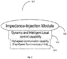
- FIG. 2 is a block diagram showing the main components of an intelligent IIM 301 .
- IIM 301 includes at least an impedance generation and injection module 102 , an intelligent control capability 402 with at least a clock with time synchronization capability, and a high-speed communication link 303 .
- an intelligent impedance injection module for use with transmission lines in a power grid, has a plurality of transformer-less impedance injector units (IIUs) and a controller.
- the controller is to change injector gain of the IIUs to compensate for power swings in a transmission line.
- an intelligent impedance injection module for use with transmission lines in a power grid, has a plurality of transformer-less impedance injector units (IIUs) and a controller.
- the controller is to change the injector gain of the IIUs to a first high gain for initial response to a detected anomaly in a transmission line.
- the controller is further to change the injector gain of the IIUs to a lower, second gain after a specified time.
- the change to the second gain may be a step function change or a dynamic and continuous change to reduce any disturbance being injected on to the transmission line due to the change.
- One embodiment is a method of impedance injection for a transmission line in a power grid.
- the method is performed by an intelligent impedance injection module (IIM).
- the IIM is coupled to the transmission line.
- the intelligent impedance injection module sets injector gain of a plurality of transformer-less impedance injector units (IIUs) of the IIM to a first, higher gain state for initial response to any sudden power transfer change incident over the transmission line.
- the intelligent impedance injection module changes the injector gain of the IIUs to a lower, second gain state after a pre-set time.
- the change to the lower gain may be a relatively dynamic and continuous change to prevent any disturbance being injected on the power line.
- FIG. 1 is a block diagram illustrating conventional distributed impedance injection modules (IIMs) attached directly to an HV transmission line with intelligent local control and utility-based control capabilities.
- IIMs distributed impedance injection modules
- FIG. 2 is a block diagram illustrating a conventional distributed dynamic intelligent impedance injection module with local and global time synchronization capability.
- FIG. 3 is a block schematic 300 of the total power system according to one embodiment.
- FIG. 4 is a block diagram of an IIU as a power flow control subsystem having four TL-FACTS based switch units.
- FIG. 5 is a diagram of interconnected in a 2 ⁇ 2 matrix of IIUs forming an IIM.
- FIG. 6 is an is a diagram 600 X of a mobile platform having three IIMs as power flow control subsystems for the three high-voltage lines of a power grid.
- FIG. 7 is a diagram of normal impedance injection with a low gain setting of the IIUs of the IIMs for generation and injection of impedance as a sinusoidal input on to the HV transmission line.
- FIG. 8 is a diagram showing a high gain setting allowing the IIUs of the IIMs to inject cumulative square wave impedance on to the HV Transmission line on identification of large change in load current.
- FIG. 9 is a diagram showing a principle of operation where the gain of the IIUs are increased on recognition of a large change in load current for a short pre-defined duration to provide response to the change while limiting or damping any oscillations after the set duration by reverting to normal low gain condition for the IIUs.
- FIG. 10 is a flow chart according to one embodiment.
- IIMs intelligent injection modules
- TL-FACTS devices for line balancing and interactive-control of High-Voltage (HV) Power lines.
- IIUs impedance injection units
- the TL-FACTS devices of the impedance injection units (IIUs) of the IIMs generate and inject capacitive or inductive waveforms in an intelligent fashion based on the corrective action needed.
- IIUs impedance injection units
- the generation and injection of the impedance for power flow correction is done reasonably slowly over a number of seconds. In the stable condition the power generation and the power utilization over the grid is matched.
- fault can be used to cover the group comprising the generator or the line trip, the line or the load switch, or any other type of fault at the generator or on the transmission line.
- instability maybe in the form of oscillations, Voltage collapse, or other transient stability problems.
- This fast response is accomplished by changing the gain setting of the IIUs to a high gain state which is then reset to the lower state after a pre-set period (t delta ), or a determination of stabilization of power transfer over the transmission lines, to prevent SSR, SSCI or other oscillation problems.
- the use of distributed self-aware and intelligent impedance injection modules (IIMs) with a plurality of Transformer-less impedance injector units connected in series-parallel configuration provide the capability to selectively change injector gains to compensate for load or generator power swings due to line switching, or line faults, or generator trip or faults that exceed a preset threshold.
- IIMs impedance injection modules
- the use of distributed self-aware and intelligent impedance injection modules (IIMs) with a plurality of Transformer-less impedance injector units connected in series-parallel configuration provide the capability to selectively change injector gains to compensate for any power swings that can create instability to the grid during re-energizing the HV transmission line after correction of the cause of the incident causing the power swing.
- IIMs impedance injection modules
- local intelligent controllers in the IIMs are able to change the gain of the impedance injector units (IIUs) for a short-preset period of time (t delta ) to a high gain state for fast response and re-set it to normal lower gain state after the pre-set time to prevent the grid system experiencing oscillations induced by the fast rise and fall times of the injected impedance.
- IIUs impedance injector units
- the method of injecting impedance using high gain setting of impedance injector units (IIU) on to the HV power lines during a sensed power swing incident during a fault reset or immediately following the detection of a significant increase or decrease in line power and the timed reset of the gain to normal value after a pre-set period in the IIUs to prevent buildup of oscillations in the grid system once the line power swing has settled.
- IIU impedance injector units
- FIG. 3 is a block schematic of a total power system according to one embodiment, with two HV power grids 910 and 920 and associated distributed impedance injection modules 301 .
- Actuator devices 500 that are enabled with distributed standardized control and communication capabilities. In one embodiment, the capabilities established for sub-cyclic control and appropriate communication for all the distributed impedance injection modules 301 are used.
- CDIIM 301 , LINCs 302 , actuator devices 500 , energy storage devices 800 , and the distributed generation capabilities 600 , as well as the distributed loads 700 are all with control capability that is typically FACTS-based and are interconnected locally using the high-speed communication capability 303 provided by the high-speed communication links 303 associated with each of the devices as shown.
- This communication capability is provided through the nearest LINC 302 , shown in FIG. 3 , for localized communication and control supervision.
- the LINCs 302 are also interconnected with high-speed link connections 303 for high-speed inter-LINC communication between the neighboring local areas.
- the LINCs 302 are further connected to the utility supervisory 206 using communication connections 305 which may be slower than the high-speed connection links 303 , to enable data transfer and overall supervisory control of the total power system.
- the control and communication capabilities of the total power system 300 are integrated using typically the FACTS-based control, and high-speed communication at each of the actuator modules, other actuator devices and miscellaneous FACTS-coupled actuator devices, and covers the total power system from generation to distribution.
- Such a system can provide optimized, dynamic, localized control of power flows from generators to loads by adjusting the generation outputs and line currents of the HV transmission grid based on system constraints and load requirements.
- the high-speed communication capabilities linking the IIM 301 , LINCs 302 , with the FACTS-coupled generators 600 , loads 700 , other actuator devices 500 , and FACTS-coupled energy storage devices 800 provide a system-level capability for localized, intelligent and capable of sub-cyclic control of all connected subsystems and devices within the total power system 300 .
- TL-FACTSs that are lower in weight and cost have also been developed and implemented as IIUs for line balancing and control.
- An example of such a TL-FACTS-based IIU 400 is shown in FIG. 4 .
- the TL-FACTS-based IIU 400 is powered by power that is extracted from the HV transmission line 108 via the secondary transformer 501 connected to the sensor and power supply block 502 , and provided to the DC power source 604 . Having DC power source 604 across the capacitor helps to improve the generation of the injected impedance across terminals 601 A-B and optimize the impedance injection onto the HV transmission line 108 .
- a local master control 503 is enabled with intelligence to respond to the power line disturbances and imbalances sensed by the sensor and power supply module 502 coupled to the power line 108 .
- the master local control 503 also has a local clock therein which is synchronizable with external clocks.
- the master local control 503 of each IIU 400 has high-speed wireless linkage or interface 410 connecting to the neighboring IIUs 400 .
- a single or a group of IIUs 400 connected in a series-parallel configuration can make up each IIM 301 , an example of which with a 2 ⁇ 2 connection is shown in FIG. 5 .
- the master local controls 503 of these connected IIUs are slaved to a selected one of the master local controls 503 which act as the interface to the other IIMs 301 and the LINCs 302 .
- the IIMs 301 connect to the LINCs 302 via the high-speed communication links 303 (as previously described).
- These high-speed communication links 303 are used to provide the switching control and in some instances synchronization signals to the master local control 503 which in turn provide the necessary control instructions to the switch control blocks 603 A-D of FACTS switches 602 where each FACTS switch 602 includes a control block (e.g., control blocks 603 A-D) and FACTS device 605 .
- FACTS device 605 includes a switching device (e.g., bipolar junction transistor (BJT), field-effect transistor (FET), metal-oxide-semiconductor field-effect transistor (MOSFET), or the like). Based on the switching control signals from master local control 503 , each of the switch control blocks 603 A-D controls its respective FACTS device 605 , typically FACTS switches using insulated gate bipolar devices (IGBT)s, which in turn controls impedance injection terminals 601 A-B that are connected in series across the HV transmission line 108 .
- IGBT insulated gate bipolar devices
- the TL-FACTS-based IIU 400 due to its low weight, allows a number of them to be connected or coupled to the HV transmission lines 108 and operate in a series-parallel mode.
- a single or a plurality of interconnected TL-FACTS-based IIU 400 may form a single IIM 300 that is connected directly to the high voltage power lines 108 and operates with a pseudo-ground at the HV powerline voltage.
- a protection switch 606 (i.e., open/close) is provided that is used to close and short the impedance injection terminals 601 A-B during fault conditions on the HV transmission line 108 and hence to bypass the circuits of the TL-FACTS-based IIU 400 included in the distributed IIM 301 and protect the FACTS devices and control circuit from damage and failure.
- FIG. 6 shows the three IIMs 301 A, B and C separated by a distance 603 X from each other as insulation.
- the three IIMs 301 A, B and C are installed on a mobile carrier 604 X on insulated stand-offs 602 X.
- the IIMs are configured to be used for power flow control and control of disturbances on the lines by injecting impedances to compensate for changes.
- These control applications operate with the IIUs 400 of the IIMs 301 s to operate with low gain setting and at a response rate wherein the control is applied over a number of seconds. Under normal operating conditions the gain of the IIUs 400 are kept low as shown in FIG. 7 .
- the IIUs 400 of the IIMs 301 inject impedance waveforms which are then combined in a timed fashion to generate a Sinusoidal waveform injected on the HV power lines.
- the use of smooth rising injection waveform 702 is needed to reduce or eliminate unwanted sub synchronous resonance (SSR), unstable Sub Synchronous Control Interactions (SSCI) related oscillations as well as generation and propagation of other harmonic oscillations over the grid system.
- SSR sub synchronous resonance
- SSCI stable Sub Synchronous Control Interactions
- multiple HV transmission line sets such as 910 and 920 carrying the three phases of load are used to connect main power generation location having multiple generators 203 to the user loads 700 .
- technical constraints aside from the thermal capability of the transmission lines can limit the amount of power that can be transmitted along said transmission lines.
- the power transfer capability can sometimes be limited by voltage collapse or transient stability problems. When these problems exist and are related to high transfer of power along transmission lines, a reduction of the series line impedance can reduce the severity of the problem and allow larger amounts of power to be transmitted on the lines.
- Voltage collapse is the phenomena where an uncontrolled and significant reduction in system voltage occurs due to the reactive power requirements of the network and connected loads not being met. This may be triggered by growth of load, loss of generation, loss of line, loss of supporting reactive plant, all of which increase the reactive power demands of the system. If left uncorrected this can have a domino effect even leading to grid system collapse.
- Transient stability is related to the ability of power system to return to a stable state, remaining intact and maintaining synchronism between generators following a large disturbance on the grid such as a line fault and trip, or loss of a significant plant item.
- angular power swings may occur as some generators accelerate and other generators decelerate due to an imbalance of generation and load in different parts of the interconnected network. Excessive angular swing between generators can lead to transient instability of the network, resulting in generator pole slipping, and potential system separation and loss of load.
- the short circuit current will cause the current flow in that line to increase by pulling the current from the HV transmission line group 902 starving the load till the safety trips operate opening up the faulty group. At that point the current in the second HV transmission line group will suddenly increase to satisfy the load.
- the increased electrical current in the remaining in-service line creates increased reactive power losses (known as ‘I-squared X’ losses) in the line that can result in exaggerated voltage drop and risk of voltage collapse.
- Similar scenario can also happen if one or more generators experience faults resulting in them going off line. This can cause a sudden increase in power transferred over the HV transmission line groups leading to increased reactive power consumption and potential for voltage collapse.
- the series reactance of the transmission line can be decreased, which reduces reactive losses in the line and improves voltage levels on the system, preventing voltage collapse.
- the use of capacitive injection on the lines to reduce their series impedance, reducing reactive power losses or reducing the power angle along the line can increase the level of power that can safely be transmitted along the lines.
- the response of the IIMs to inject a voltage waveform to create a capacitive injection needs to be at a much faster and higher rate to address the voltage and transient stability issues.
- a response time of only a few cycles with high injection rate can be used to provide maximum benefits to the grid.
- the present disclosure addresses the need for control to be available for sudden large supply current or load changes 701 in non-faulty lines, as well as lines being re-energized after a trip.
- the capability of IIUs 400 of the IIMs 301 capable of injecting impedance are then changed such that their gain is increased.
- the increase in gain allows the IIUs 400 to respond rapidly injecting fast rising 801 pulses into the HV grid lines as shown in FIG. 8 to compensate for large load changes 701 which improves the voltage collapse and transient stability conditions of the grid, allowing large level of power to be safely transmitted across the network.
- the problem of high gain that enable the injection of cumulative large fast rising 801 pulses instead of smooth rising 702 pulses to correct large swings in line current 701 is that oscillations 802 can be generated and propagated over the HV transmission lines. These oscillations can be due to SSR and SSCI as well as harmonics generated by the fast-rising impedance injection.
- This embodiment allows the IIUs 400 to enter the high gain state enabling a fast rise 801 of impedance injection on recognition of high load swings 701 for a pre-determined time required for verification of fault.
- the gain of the IIUs 400 injecting the impedance onto the line is set back to its normal low value.
- Such a method of controlling the impedance injection response allow the grid system to respond efficiently to large load current swings 701 while keeping the propensity for sustained oscillations 802 low.
- FIG. 10 shows a flow chart of such method.
- the gain of the impedance injector circuits are set to low to reduce any propensity for oscillations on the HV transmission lines of the grid.
- Sensors coupled to the HV power lines of the grid system operate to sense any changes in power flow over the grid and or disturbances and any deviations to flow are informed to the master controllers in the local IIMs and to the utility.
- the local IIMs comprising one or more interconnected FACTS-based IIUs using the intelligence built in or on communicated commands, e.g., from a utility, respond to the sensed information by injecting impedances to balance the power flow and keep the grid system in balance.
- High power swing information is also communicated to the master control in the local IIMs, the LINCs and the system utility over available communication links.
- the master controller of the IIM evaluates the received information.
- the master controller at the IIM checks the information to see if the power swing exceeds a “fault” threshold setting of power deviation that requires the IIMs to be put in a by-pass mode to prevent damage. S 1004 .
- the IIMs continuously monitor the HV transmission line and received communication to see if the fault has been cleared and the HV transmission line is operational. As long as the fault remains the IIMs remain in the by-pass mode. S 1006 .
- the power swing is checked against a pre-set threshold over which system instabilities can happen. If the power swing does not exceed this pre-set threshold value the system goes back to normal operation. S 1007 .
- the countdown is started and the command is sent to the IIMs in the local area to increase the injector gain setting of the IIUs and engage on the HV transmission line injecting impedance on to the HV transmission lines for the timer pre-set period of t delta as required by one embodiment.
- S 1009 is .
- the count-down timer is checked to see if the t delta time has elapsed. S 1010 . If the result of the check is negative the gain of the impedance injectors is kept high as at S 1009 while checking of elapse time t delta is repeated. S 1011
- the master controller sends out a command to all the IIMs under local control to reset the impedance injector gain to normal operating value (low).
- the operation of the HV transmission line group without fault are returned to normal operation S 1012 .
- the use of distributed self-aware and intelligent impedance injection modules (IIMs) with a plurality of Transformer-less impedance injector units connected in series-parallel configuration provide the capability to selectively change injector gains to compensate for load current swings due to line switching, or line faults, or generator faults that exceed a preset threshold.
- IIMs impedance injection modules
- the use of distributed self-aware and intelligent impedance injection modules (IIMs) with a plurality of Transformer-less impedance injector units connected in series-parallel configuration provide the capability to selectively change injector gains to compensate for current swings that can create instability during re-energizing the HV transmission line after a fault related incident
- local intelligent controllers in the IIMs are able to change the gain of the impedance injector units (IIUs) for a short-preset period of time (t delta ) to a high gain state for fast response and re-set it to normal lower gain state after the pre-set time to prevent the grid system experiencing oscillations induced by the fast rise and fall times of the injected impedance.
- IIUs impedance injector units
- the method of injecting impedance using high gain setting of impedance injector units (IIU) on to the HV power lines during a sensed high power change incident during a fault reset or immediately following the detection of a significant increase or decrease in power transfer and the timed reset of the gain to normal value after a pre-set period in the IIUs to prevent buildup of oscillations in the grid system once the line power change has settled.
- IIU impedance injector units
Landscapes
- Engineering & Computer Science (AREA)
- Power Engineering (AREA)
- Physics & Mathematics (AREA)
- General Physics & Mathematics (AREA)
- Automation & Control Theory (AREA)
- Supply And Distribution Of Alternating Current (AREA)
Abstract
Description
Claims (19)
Priority Applications (1)
| Application Number | Priority Date | Filing Date | Title |
|---|---|---|---|
| US16/838,720 US11539211B2 (en) | 2019-06-11 | 2020-04-02 | Fast-slow injection for recovery from transient response and voltage collapse with avoidance of SSR and SSCI |
Applications Claiming Priority (2)
| Application Number | Priority Date | Filing Date | Title |
|---|---|---|---|
| US201962860159P | 2019-06-11 | 2019-06-11 | |
| US16/838,720 US11539211B2 (en) | 2019-06-11 | 2020-04-02 | Fast-slow injection for recovery from transient response and voltage collapse with avoidance of SSR and SSCI |
Publications (2)
| Publication Number | Publication Date |
|---|---|
| US20200395756A1 US20200395756A1 (en) | 2020-12-17 |
| US11539211B2 true US11539211B2 (en) | 2022-12-27 |
Family
ID=73746310
Family Applications (1)
| Application Number | Title | Priority Date | Filing Date |
|---|---|---|---|
| US16/838,720 Active 2041-07-01 US11539211B2 (en) | 2019-06-11 | 2020-04-02 | Fast-slow injection for recovery from transient response and voltage collapse with avoidance of SSR and SSCI |
Country Status (1)
| Country | Link |
|---|---|
| US (1) | US11539211B2 (en) |
Cited By (1)
| Publication number | Priority date | Publication date | Assignee | Title |
|---|---|---|---|---|
| US11831271B1 (en) * | 2021-06-09 | 2023-11-28 | Aderis Energy, Llc | Medium voltage inrush current regulation and interconnection control system and method |
Families Citing this family (4)
| Publication number | Priority date | Publication date | Assignee | Title |
|---|---|---|---|---|
| US11349310B2 (en) * | 2019-11-15 | 2022-05-31 | Smart Wires Inc. | Adaptive control technique for stability of impedance injection unit |
| US11641102B2 (en) * | 2020-03-10 | 2023-05-02 | Smart Wires Inc. | Modular FACTS devices with external fault current protection within the same impedance injection module |
| US11394375B2 (en) * | 2020-10-14 | 2022-07-19 | Smart Wires Inc. | Sinusoidal wave formation for reduction of oscillations, harmonics and distortion using short pulses to reduce the number of required impedance injection units |
| EP4273564A1 (en) * | 2022-05-02 | 2023-11-08 | Siemens Aktiengesellschaft | Apparatus, system and method for detecting anomalies in a grid |
Citations (9)
| Publication number | Priority date | Publication date | Assignee | Title |
|---|---|---|---|---|
| US5166597A (en) * | 1991-08-08 | 1992-11-24 | Electric Power Research Institute | Phase-shifting transformer system |
| US5198746A (en) * | 1991-09-16 | 1993-03-30 | Westinghouse Electric Corp. | Transmission line dynamic impedance compensation system |
| US5227713A (en) * | 1991-08-08 | 1993-07-13 | Electric Power Research Institute | Vernier control system for subsynchronous resonance mitigation |
| US5642007A (en) * | 1994-12-30 | 1997-06-24 | Westinghouse Electric Corporation | Series compensator inserting real and reactive impedance into electric power system for damping power oscillations |
| US5698969A (en) * | 1995-11-29 | 1997-12-16 | Westinghouse Electric Corporation | Apparatus and method for interline power flow control |
| US20080310069A1 (en) * | 2005-01-31 | 2008-12-18 | Deepakraj Malhar Divan | Systems and Methods for Distributed Series Compensation of Power Lines Using Passive Devices |
| US20110012583A1 (en) * | 2009-07-17 | 2011-01-20 | Searete Llc, A Limited Liability Corporation Of The State Of Delaware | Use pairs of transformers to increase transmission line voltage |
| US20140055163A1 (en) * | 2011-12-16 | 2014-02-27 | Hongjiang Song | Low voltage transmitter with variable output swing |
| US20170237255A1 (en) * | 2016-02-11 | 2017-08-17 | Smart Wires Inc. | Dynamic and Integrated Control of Total Power System Using Distributed Impedance Injection Modules and Actuator Devices Within and at the Edge of the Power Grid |
-
2020
- 2020-04-02 US US16/838,720 patent/US11539211B2/en active Active
Patent Citations (9)
| Publication number | Priority date | Publication date | Assignee | Title |
|---|---|---|---|---|
| US5166597A (en) * | 1991-08-08 | 1992-11-24 | Electric Power Research Institute | Phase-shifting transformer system |
| US5227713A (en) * | 1991-08-08 | 1993-07-13 | Electric Power Research Institute | Vernier control system for subsynchronous resonance mitigation |
| US5198746A (en) * | 1991-09-16 | 1993-03-30 | Westinghouse Electric Corp. | Transmission line dynamic impedance compensation system |
| US5642007A (en) * | 1994-12-30 | 1997-06-24 | Westinghouse Electric Corporation | Series compensator inserting real and reactive impedance into electric power system for damping power oscillations |
| US5698969A (en) * | 1995-11-29 | 1997-12-16 | Westinghouse Electric Corporation | Apparatus and method for interline power flow control |
| US20080310069A1 (en) * | 2005-01-31 | 2008-12-18 | Deepakraj Malhar Divan | Systems and Methods for Distributed Series Compensation of Power Lines Using Passive Devices |
| US20110012583A1 (en) * | 2009-07-17 | 2011-01-20 | Searete Llc, A Limited Liability Corporation Of The State Of Delaware | Use pairs of transformers to increase transmission line voltage |
| US20140055163A1 (en) * | 2011-12-16 | 2014-02-27 | Hongjiang Song | Low voltage transmitter with variable output swing |
| US20170237255A1 (en) * | 2016-02-11 | 2017-08-17 | Smart Wires Inc. | Dynamic and Integrated Control of Total Power System Using Distributed Impedance Injection Modules and Actuator Devices Within and at the Edge of the Power Grid |
Cited By (2)
| Publication number | Priority date | Publication date | Assignee | Title |
|---|---|---|---|---|
| US11831271B1 (en) * | 2021-06-09 | 2023-11-28 | Aderis Energy, Llc | Medium voltage inrush current regulation and interconnection control system and method |
| US12166450B2 (en) | 2021-06-09 | 2024-12-10 | Aderis Energy, Llc | Medium voltage inrush current regulation and interconnection control system and method |
Also Published As
| Publication number | Publication date |
|---|---|
| US20200395756A1 (en) | 2020-12-17 |
Similar Documents
| Publication | Publication Date | Title |
|---|---|---|
| US11539211B2 (en) | Fast-slow injection for recovery from transient response and voltage collapse with avoidance of SSR and SSCI | |
| Karimi et al. | Under-frequency load shedding scheme for islanded distribution network connected with mini hydro | |
| US9019673B2 (en) | Fault detection and short circuit current management technique for inverter based distributed generators (DG) | |
| Said et al. | Coordinated fuzzy logic‐based virtual inertia controller and frequency relay scheme for reliable operation of low‐inertia power system | |
| Abedrabbo et al. | Impact of DC grid contingencies on AC system stability | |
| US20140056041A1 (en) | Power generation system, power converter system, and methods of operating a power converter system | |
| AU2021350474B2 (en) | Distribution power system fault control apparatus and method | |
| CN105870893B (en) | The relaying configuration method of microgrid group | |
| CN118137512A (en) | A droop control inverter fault ride-through control method and system | |
| US20230216301A1 (en) | Power Flow Control System for a Distribution Grid Having a Grid Forming Capability | |
| CN106208098B (en) | A kind of SVG and fixed reactive-load compensation equipment control method for coordinating and system | |
| CA3089965C (en) | Coordinated frequency load shedding protection method using distributed electrical protection devices | |
| CN105372529A (en) | Power grid islanding detection and anti-islanding protection method for large-scale wind power generation system | |
| CN107658898A (en) | A photovoltaic power station-level anti-islanding protection method and system | |
| Swain et al. | Mitigation of voltage sag and voltage swell by dynamic voltage restorer | |
| CN114498724A (en) | Control method and device for wind generating set and wind power plant | |
| Shabani et al. | DC microgrid protection in the presence of the photovoltaic and energy storage systems | |
| CN111201688A (en) | Method for controlling a high-voltage direct-current network in the event of a fault | |
| Huang et al. | Autonomous control, operation, and protection of the FREEDM system | |
| Sishuba et al. | Adaptive control system for continuity of supply using dispersed generators | |
| CN107508291A (en) | A kind of transient voltage control method for coordinating and system | |
| JPH10304574A (en) | Power transmission plant | |
| CN105978017A (en) | Method for detection and protection of island with anti-theft and anti-tripping function aiming at large-scale wind power | |
| US20230109775A1 (en) | Grid Forming Over Distribution Grid with Renewable Sources and Loads | |
| Liu et al. | Smooth Mode Switching Control Strategy for Flexible Interconnected Distribution Network |
Legal Events
| Date | Code | Title | Description |
|---|---|---|---|
| AS | Assignment |
Owner name: SMART WIRES INC., CALIFORNIA Free format text: ASSIGNMENT OF ASSIGNORS INTEREST;ASSIGNOR:HARRINGTON, PAUL;REEL/FRAME:052300/0814 Effective date: 20191212 |
|
| FEPP | Fee payment procedure |
Free format text: ENTITY STATUS SET TO UNDISCOUNTED (ORIGINAL EVENT CODE: BIG.); ENTITY STATUS OF PATENT OWNER: SMALL ENTITY |
|
| FEPP | Fee payment procedure |
Free format text: ENTITY STATUS SET TO SMALL (ORIGINAL EVENT CODE: SMAL); ENTITY STATUS OF PATENT OWNER: SMALL ENTITY |
|
| STPP | Information on status: patent application and granting procedure in general |
Free format text: APPLICATION DISPATCHED FROM PREEXAM, NOT YET DOCKETED |
|
| STPP | Information on status: patent application and granting procedure in general |
Free format text: DOCKETED NEW CASE - READY FOR EXAMINATION |
|
| AS | Assignment |
Owner name: INNOVATUS LIFE SCIENCES LENDING FUND I, LP, NEW YORK Free format text: INTELLECTUAL PROPERTY SECURITYAGREEMENT;ASSIGNOR:SMART WIRES INC.;REEL/FRAME:058653/0190 Effective date: 20211231 |
|
| STPP | Information on status: patent application and granting procedure in general |
Free format text: NOTICE OF ALLOWANCE MAILED -- APPLICATION RECEIVED IN OFFICE OF PUBLICATIONS |
|
| STPP | Information on status: patent application and granting procedure in general |
Free format text: PUBLICATIONS -- ISSUE FEE PAYMENT VERIFIED |
|
| STCF | Information on status: patent grant |
Free format text: PATENTED CASE |