EP2587602A2 - Active current surge limiters with watchdog circuit - Google Patents
Active current surge limiters with watchdog circuit Download PDFInfo
- Publication number
- EP2587602A2 EP2587602A2 EP13150514.1A EP13150514A EP2587602A2 EP 2587602 A2 EP2587602 A2 EP 2587602A2 EP 13150514 A EP13150514 A EP 13150514A EP 2587602 A2 EP2587602 A2 EP 2587602A2
- Authority
- EP
- European Patent Office
- Prior art keywords
- current
- circuit
- relay
- control signal
- input
- Prior art date
- Legal status (The legal status is an assumption and is not a legal conclusion. Google has not performed a legal analysis and makes no representation as to the accuracy of the status listed.)
- Withdrawn
Links
Images

Classifications
-
- H—ELECTRICITY
- H02—GENERATION; CONVERSION OR DISTRIBUTION OF ELECTRIC POWER
- H02J—CIRCUIT ARRANGEMENTS OR SYSTEMS FOR SUPPLYING OR DISTRIBUTING ELECTRIC POWER; SYSTEMS FOR STORING ELECTRIC ENERGY
- H02J3/00—Circuit arrangements for ac mains or ac distribution networks
- H02J3/18—Arrangements for adjusting, eliminating or compensating reactive power in networks
- H02J3/1807—Arrangements for adjusting, eliminating or compensating reactive power in networks using series compensators
-
- H—ELECTRICITY
- H02—GENERATION; CONVERSION OR DISTRIBUTION OF ELECTRIC POWER
- H02H—EMERGENCY PROTECTIVE CIRCUIT ARRANGEMENTS
- H02H9/00—Emergency protective circuit arrangements for limiting excess current or voltage without disconnection
- H02H9/02—Emergency protective circuit arrangements for limiting excess current or voltage without disconnection responsive to excess current
-
- Y—GENERAL TAGGING OF NEW TECHNOLOGICAL DEVELOPMENTS; GENERAL TAGGING OF CROSS-SECTIONAL TECHNOLOGIES SPANNING OVER SEVERAL SECTIONS OF THE IPC; TECHNICAL SUBJECTS COVERED BY FORMER USPC CROSS-REFERENCE ART COLLECTIONS [XRACs] AND DIGESTS
- Y02—TECHNOLOGIES OR APPLICATIONS FOR MITIGATION OR ADAPTATION AGAINST CLIMATE CHANGE
- Y02E—REDUCTION OF GREENHOUSE GAS [GHG] EMISSIONS, RELATED TO ENERGY GENERATION, TRANSMISSION OR DISTRIBUTION
- Y02E40/00—Technologies for an efficient electrical power generation, transmission or distribution
- Y02E40/30—Reactive power compensation
Abstract
Description
- The present disclosure is generally related to limiting current surge and, more particularly, embodiments of the present disclosure are related to actively limiting surge current produced by power supply disturbances during load operation.
- There are many applications where it is necessary to protect electrical equipment from power surges and high energy transients that could damage or adversely affect the operation of such equipment. Voltage surges are commonly perceived to be the most common cause for damage to electrical equipment during operation. Voltage surges, such as those produced by lightning strikes, can cause large currents to flow resulting in damage to operating equipment. Electrical equipment utilizing electronics, such as a rectifier front end, are particularly susceptible to damage. As a result, transient voltage surge suppressors (TVSS) are commonly utilized to clamp the voltage level and absorb energy associated with a transient. However, analysis strongly suggests that there is a fairly high probability that equipment will be also be damaged by current surges that occur at the end of voltage sags. Furthermore, industrial studies have indicated that voltage sags are much more likely to occur than voltage surges. While TVSS devices limit the voltage applied to equipment, they do not limit the current surge experienced by electrical equipment at the end of voltage sag transients.
- High inrush currents are also commonly experienced during the starting of electrical equipment. Inrush current limiting circuits, including a negative temperature coefficient (NTC) thermistor or resistor connected between a power supply and a protected load and a bypass switch in parallel with the NTC thermistor, are often used to mitigate the current surge seen by the load during starting. A NTC thermistor is a component with a resistance that decreases as its temperature increases. During startup, the temperature of the NTC thermistor is cold and its resistance is high. As operation continues, the temperature increases and the resistance of the NTC thermistor decreases, allowing more current during normal operation. Once the equipment has completed its startup or a preset time has elapsed, the bypass switch closes to remove the resistor from between the power supply and the electrical load. The current limiter circuit remains disabled until the equipment is de-energized and the bypass switch is reopened. While the inrush current limiter circuits limit the current surge during startup, these inrush current limiter circuits do not provide protection from electrical transients during normal operation of the electrical equipment.
- An AC current limiting circuit including a current limiter, a disturbance sensor and an activator is known from US patent
US 4,924,342. - An overcurrent protection system is known from US patent
US 5,689,395 . - Briefly described, embodiments of this disclosure, among others, include active current surge limiters and methods of use.
- One exemplary system, among others, comprises a current limiter, including an interface configured to be connected between a power supply and a load; a disturbance sensor, configured to monitor the power supply for a disturbance during operation of the load; and an activator, configured to receive a control signal from the disturbance sensor and to activate the current limiter based on the control signal.
- The power supply may be an alternating current (AC) power supply.
- A circuit breaker may be tripped to de-energize the load when the disturbance continues beyond a preset period.
- The current limiter may include at least one of the group consisting of: a resistor, an NTC thermistor, and a varistor.
- The disturbance sensor may monitor at least one of the group consisting of: voltage, current, and combinations thereof.
- The disturbance may be a voltage sag.
- The disturbance may also be a current surge. A current limit may be preset. The current limit may be determined by the disturbance sensor. The current limit may be based on starting current of the load.
- The activator may include a bypass circuit. The bypass circuit may include at least one of the group consisting of: an electromechanical relay, a semiconductor switch, a triac, a thyristor.
- The current limiter may be activated while the disturbance detected.
- Another exemplary system, among others, comprises means for limiting current supplied to a load from a power supply; means for sensing a disturbance on the power supply during operation of the load; and means for activating the means for limiting current to the load when a disturbance is sensed.
- The system may further include means for de-energizing the load when the disturbance exceeds a preset period.
- Methods of use are also provided. One exemplary method, among others, comprises monitoring a condition of a power supply during operation of a load connected to the power supply; determining if the condition falls outside of an acceptable limit; and activating a current limiting device when the monitored condition falls outside of acceptable limits.
- The monitored condition may include voltage, current, and combinations thereof.
- The acceptable limit may be determined based on variations of the monitored condition during operation of the load.
- The current limiting device may be deactivated when the monitored condition falls within acceptable limits.
- The current limiting device may be deactivated after a preset period of time.
- Other structures, systems, methods, features, and advantages will be, or become, apparent to one with skill in the art upon examination of the following drawings and detailed description. It is intended that all such additional structures, systems, methods, features, and advantages be included within this description, be within the scope of the present disclosure.
- Many aspects of the disclosure can be better understood with reference to the following drawings. The components in the drawings are not necessarily to scale, emphasis instead being placed upon clearly illustrating the principles of the present disclosure. Moreover, in the drawings, like reference numerals designate corresponding parts throughout the several views.
- Fig. 1
- illustrates an active current surge limiter.
- Fig. 2
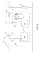
- is an alternative embodiment of the active current surge limiter utilizing a microcontroller and semiconductor switches.
- Fig. 3
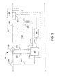
- is an alternative embodiment of the active current surge limiter utilizing a microcontroller and an electromechanical relay.
- Fig. 4
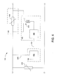
- is an alternative embodiment of the active current surge limiter utilizing a voltage detector and an electromechanical relay.
- Fig. 5
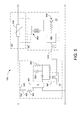
- is an alternative embodiment of the active current surge limiter utilizing an optocoupler and an electromechanical relay.
- Fig. 6
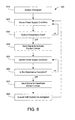
- is a flow chart illustrating an embodiment of a fast detection algorithm for the active current surge limiter.
- Voltage sags have been shown to occur fairly frequently in industrial settings. Studies indicate that voltage sags are 100 to a 1000 times more likely to occur than voltage surges. Data and analysis strongly suggest a high probability that operating equipment will be damaged by a current surge that occurs at the end of the voltage sag. The most vulnerable point for typical equipment is the end of short-duration sags, when the inrush limiting circuits are normally disabled. The current surge can have excessively high 12T ratings because the normal inrush limiting circuit (NTC thermistor or resistor + bypass switch) is disabled. The current surge causes damage to equipment, as well as degradation of components leading to shortened equipment life and premature equipment failure. Industrial, commercial and residential equipment that are potentially subject to the problem include, but are not limited to, PC's, servers, TV's, stereo amplifiers, microwave ovens, PLC's, robots, machine drives, medical equipment, etc.
- Embodiments of active current surge limiters are described below. It should be emphasized that the described embodiments are merely possible examples of implementations, and are set forth for clear understanding of the principles of the present disclosure, and in no way limit the scope of the disclosure.
-
Fig. 1 illustrates an active current surge limiter. The activecurrent surge limiter 100 is connected at an interface between apower supply 110 and aload 120. Power supplies include AC and/or DC sources. While the principles discussed are generally applied to applications up to 1000 Volts, this does not prevent their use in applications at higher voltage levels. Loads that are sensitive to these disturbances include, but are not limited to, industrial, commercial and residential equipment that include power electron components. A transient voltage surge suppressor (TVSS) 130 connected on the input side can provide the added functionality of a voltage surge suppressor device. The activecurrent surge limiter 100 includes acurrent limiter 140 for limiting the current supplied to theconnected load 120, adisturbance sensor 150 for monitoring the condition of thepower supply 110, and anactivator 160 for activating thecurrent limiter 140 when the disturbance sensor detects a disturbance on the power supply. - Disturbances in the power supply can include variations in the power supply characteristics such as, but are not limited to, the voltage, current, and combinations thereof. The presence of a power supply disturbance is indicated when the sensed characteristic falls outside established operational limits. Operational limits can be preset based on variables such as, but not limited to, industrial standards and known load and supply characteristics. However, as the power supply and load characteristics are typically unknown, establishment of allowable current limits can require additional analysis. Another alternative is to allow the
disturbance sensor 150 to establish limits based on continuous monitoring of selected supply characteristics. -
Fig. 2 is an alternative embodiment of the active current surge limiter utilizing a microcontroller and semiconductor switches. This non-limiting embodiment of an activecurrent surge limiter 100, thedisturbance sensor 150 uses a microprocessor ormicrocontroller 200 to establish allowable current limits, continuously monitor power supply characteristics (i.e.sensing voltage 205 and current 210), and communicate acontrol signal 215 to theactivator 160 indicating the presence of a disturbance on the power supply. The described control strategy allows the activecurrent surge limiter 100 to handle power-up and load change without problems. - To establish the allowable current limit, the circuit in
Fig. 2 senses and measures the current 210 drawn by theload 120, including peak current at start-up, through acurrent transformer 220. The peak current at start-up is stored in a peak-rectifier circuit (not shown), including a diode and capacitor coupled with a current transformer, and measured by an A/D converter incorporated in themicrocontroller 200. One skilled in the art would realize that other measurement circuits could also be utilized to measure power supply characteristics. The starting current is recorded and stored by themicrocontroller 200 as a peak inrush current. During operation of theload 120, themicrocontroller 200 continues to monitor the load current 210 and record any sensed peak currents. - The
microcontroller 200 also monitors the incomingac line voltage 205. Limits for the sensedvoltage 205 can be preset or established by themicrocontroller 200. Voltage sags occur when a supply voltage drops below 90% of rated voltage for short periods of time of one half cycle or more. When a sag in the monitoredline voltage 205 is detected by themicrocontroller 200, a peak current limit reference (Imax) is set to the maximum peak current value thus far recorded. During the voltage sag, the current drawn by the load is most likely to decrease. At the end of the voltage sag, the voltage quickly returns to normal, causing a surge in the sensed current 210. The magnitude of the surge current is affected by load factors, such as the type, condition, and proximity as well as power supply factors, such as duration of disturbance, line impedance, and transformer location. Industrial, commercial and residential equipment vulnerable to the effects of current surges include, but not limited to, PC's, servers, TV's, stereo amplifiers, microwave ovens, PLC's, robots, machine drives, and medical equipment. Moreover, any equipment utilizing rectifier/capacitor circuits amplify the surge current effects when the capacitor is substantially discharged during a voltage sag. - Once the
microcontroller 200 detects a current level that exceeds the Imax threshold, acontrol signal 215 is sent to theactivator 160 indicating the presence of a disturbance. In this non-limiting embodiment, thecurrent limiter 140 is activated by turning off asemiconductor switch 225 through agate drive 230. Activation of thecurrent limiter 140 forces the load current to flow through an acvoltage clamping device 235, such as but not limited to, a varistor. The voltage impressed across theload 120 is reduced, limiting the current supplied to the load. Theswitch 225 can then be turned on at, but not limited to, the next cycle, a zero crossing point, and a predetermined number of switching under a high frequency duty cycle control scheme as is customary in PWM circuits. If the sensed current 210 remains high for greater than a preset period of time, such as but not limited to one to two seconds, then atrip signal 240 is activated by themicrocontroller 200, opening an overload switch orcircuit breaker 245 and shutting the system down until a reset is effectuated, e.g., a reset button is pressed. Incorporation of avoltage clamping device 250 provides additional voltage surge protection to theconnected load 120. - The use of gate turn-off
devices 225 allows turn-off and over-current protection even under normal voltage conditions as well as in the presence of fast rising current fronts that occur under fault conditions. For successful operation, the components are sized to handle trapped energy in line and load inductances. In addition, power dissipation during continuous operation should be considered during selection. -
Fig. 3 is an alternative embodiment of the active current surge limiter utilizing a microcontroller and an electromechanical relay. This non-limiting embodiment utilizes thesame disturbance sensor 150 tosense voltage 205 and current 210 as depicted inFig. 2 . During normal operation, thecurrent limiter 140 can be bypassed using an electromechanical relay, contactor or switch. In this depiction, acontrol signal 215 sent by themicrocontroller 200 causes a normally-open relay 355 to close and deactivate thecurrent limiter 140. The power supply is continuously monitored as described forFig. 2 . - Fast detection algorithms (e.g., as described in
Fig. 6 ) allow the detection of supply disturbances within one quarter to one half cycle. Fast detection algorithms can be implemented in, but not limited to, software, hardware and/or individual components. Because the line current drawn by the load typically drops dramatically when the DC capacitor reverse biases the diode bridge during a voltage sag, a voltage sag that is likely to cause inrush current can be can readily detected. Upon detecting the onset of the voltage sag, thecontrol signal 215 causes therelay 355 to open and activating thecurrent limiter 140. - The
current limiter 140 in this embodiment includes two resistors, 360 and 365, with a thyristor pair ortriac 370 connected in parallel with thesecond resistor 365. Alternative combinations can also be utilized. Upon exceeding Imax,resistors triac 370 is turned on, allowing higher current levels. Control of thetriac 370 is provided by asignal 375 sent by themicrocontroller 200 to agate driver 330 for thetriac 370. Once the sensed current 210 subsides or after sufficient time has elapsed, therelay 355 is reclosed allowing normal load operation to resume. As described forFig. 2 , if the sensed current 210 remains high for a predetermined period, atrip signal 240 is activated by themicrocontroller 200, opening an overload switch orcircuit breaker 245 and shutting the system down. - With the use of a multi-step
current limiter 140, it is possible to significantly improve the performance so as to minimize impact on the load. The level of surge current that flows in the system depends on a number of parameters including, but not limited to, the depth and duration of the voltage sag, the load rating, the short circuit current available at the load point, and the amount of capacitance in the load rectifier. Monitoring of Imax provides an indication of the load characteristics and maximum current necessary for normal operation. The current flowing through theresistors triac 370 is turned on at an angle α, the difference between the line and DC bus voltages (Vline - Vdc) is applied acrossresistor 360 and allowing an increase in current flow to theload 120. Neglecting line and load inductances, the line current decreases until, at an angle β, it reaches to zero when the line voltage equals Vdc. By controlling the turn-on oftriac 370, it is possible to control the average current supplied to the load capacitance and minimize recovery time. As Vdc increases with capacitor charging, α automatically changes to keep the line current limited and under control. Once the current drawn by load has returned to within allowable limits, therelay 355 can be closed again, allowing normal operation to resume. - This approach allows us to match the allowed inrush current to the load characteristic, as represented by Imax, and the average current drawn by the load, without requiring the use of gate turn-off
devices 225. In addition, the use oftriacs 370 simplifies the gating and control requirements, reducing cost and complexity. Furthermore, as thetriac 370 and theresistors relay 355 and only operate during transients, the power dissipation requirements are minimal, allowing packaging in a more compact form. Other combinations of resistors and switching elements, such as but not limited to triacs, can be used to control current flow. - This embodiment can also provide a soft start process for equipment without built-in startup protection. Upon power-up, a two stage soft start process is initiated. First,
resistors triac 370 is turned on to allow higher current levels. Finally, once the current level again subsides or sufficient time has elapsed, therelay 355 is closed allowing normal load operation to begin. -
Fig. 4 is an alternative embodiment of the active current surge limiter utilizing a voltage detector and an electromechanical relay. In this non-limiting embodiment, a normally-open relay 455 is used to activate thecurrent limiter 140 which includes a resistor or Negative Temperature Coefficient (NTC)thermistor 435. TheNTC thermistor 435 has a high resistance value when cold. The resistance drops dramatically as theNTC thermistor 435 heat up, often by a factor of 10 or more, allowing higher currents to flow. The high resistance returns as theNTC thermistor 435 cools off. Manufacturers typically specify cooling times of up to 60 seconds or more. - At startup, the
relay 455 is maintained off (open) and theNTC thermistor 435 limits the inrush current that flows. As current flows, the resistance of theNTC thermistor 435 decreases providing less current limitation. After a preset time delay, therelay 455 is turned on to de-energize thecurrent limiter 140 by bypassing theNTC thermistor 435. This allows theNTC thermistor 435 to cool down and restore the high resistance mode. - A
detector circuit 400 is implemented that identifies when a voltage sag occurs, and send acontrol signal 415 to activate thecurrent limiter 140. One of many possible implementations of thedetector circuit 400 utilizes a microprocessor with an A/D converter to sense and measure theline voltage 405. The microprocessor identifies when the voltage falls outside a nominally acceptable boundary defined by a preset limit. When a disturbance is detected, thedetector circuit 400 sends acontrol signal 415 to atimer circuit 480 which causes therelay 455 to close and activate thecurrent limiter 140. As described above, the resistance of theNTC thermistor 435 decreases until a preset time is reached. At that point, thetimer circuit 480, de-energizes therelay 455 bypassing theNTC thermistor 435. Incorporation of avoltage clamping device 450 provides additional voltage surge protection to both theconnected load 120 and the activecurrent surge limiter 100. -
Fig. 5 is an alternative embodiment of the active current surge limiter utilizing an optocoupler and an electromechanical relay. This non-limiting embodiment uses a circuit for simulating the operation of a DC power supply in the disturbance sensor. Thediode bridge 501 and thecapacitor 502 represent a typical rectifier/capacitor circuit that may be used in aload 120. Theinductance 503 andresistance 504 simulate effective line impedance. The time constant of theload resistor 506 andcapacitor 502 is chosen to be similar to that found in rectifier/capacitor circuits. This circuit simulates the operation of a high power rectifier/capacitor circuit at low cost. Thecapacitor 502 is charged from the line at the peaks of the sensedline voltage 505, as the simulated load would. Anoptocoupler 507 is used to detect the charging current pulse at the line voltage peaks and send acontrol signal 515 to theactivator 160. - A retriggerable monostable multi-vibrator 590 with an output pulse greater than one half cycle (8.33 mS) is triggered by the control signal 515 from the
optocoupler 507. As long as the charging current pulses occur every half cycle, the monostable multi-vibrator 590 remains triggered. The output of the monostable multi-vibrator 590 is used to close therelay 555 through asemiconductor switch 595, such as but not limited to, a transistor. While the line voltage is within specified limits, therelay 555 is maintained closed, de-energizing thecurrent limiter 140 by bypassing a current limitingdevice 535, such as but not limited to, an NTC thermistor, triac, and resistor. - If the sensed
voltage 505 decreases in amplitude below the simulated DC bus voltage, the charging current pulses stop, causing theoptocoupler 507 to stop sending triggering pulses as thecontrol signal 515. When the triggering pulses stop, monostable multi-vibrator 590 output changes state at the end of the timing period, causingswitch 595 to turn the relay off. This then reinserts the current limitingdevice 535 into the circuit limiting the inrush current to theload 120. Then the AC line voltage returns to normal, the charging current pulses begin again and the monostable multi-vibrator 590 is retriggered once again. After waiting for a preset time, therelay 555 is closed once again, de-energizing thecurrent limiter 140. -
Fig. 6 is a flow chart illustrating an embodiment of afast detection algorithm 600 for the active current surge limiter.Fast detection algorithms 600 can be implemented in, but not limited to, software, hardware and/or individual components, as illustrated in the previous embodiments ofFig. 2-5 . In this non-limiting embodiment of afast detection algorithm 600, the activecurrent surge limiter 100 is energized 610 upon starting theconnected load 120. The activecurrent surge limiter 100 begins sensing thepower supply conditions 620. This can include, but is not limited to, voltage, current, and combinations thereof. The sensed conditions are then evaluated to determine if a disturbance exists 630. If it is determined that no disturbance exists, then the activecurrent surge limiter 100 continues to sense 620 and evaluate 630 the power supply condition. If a disturbance does exist, then thecurrent limiter 140 is activated 640. - Once the
current limiter 140 is activated, the activecurrent surge limiter 100 returns sensing thepower supply conditions 650. The sensed conditions are then evaluated to determine if the disturbance is complete 660. If it is determined that the disturbance still exists, then the activecurrent surge limiter 100 continues to sense 650 and evaluate 660 the power supply condition. If the disturbance no longer exists, then thecurrent limiter 140 is deactivated 670. The process repeats until the activecurrent surge limiter 100 and itsload 120 are de-energized. - It should be emphasized that the above-described embodiments of the present disclosure are merely possible examples of implementations, and are merely set forth for a clear understanding of the principles of the disclosure. Many variations and modifications may be made to the above-described embodiments. For example, a plurality of devices can be included in the current limiter to provide active of passive current limitation. In addition, a plurality circuits utilizing integrated circuits or discrete components can be implemented to provide disturbance sensing and activation of the current limiter. Moreover, other automated methods to determine voltage and current limitations can be incorporated into active current surge limiters. All such modifications and variations are intended to be included herein within the scope of this disclosure.
Claims (15)
- An active current surge limiting apparatus for reduction of inrush current to an electrical load in response to detection of a disturbance in an input AC power supply coupled to the electrical load, comprising:a current-limiting circuit coupled between the input power supply and the electrical load, the current-limiting circuit comprising a parallel arrangement of(a) a current limiter, and(b) a relay having contacts that are in a normally-open position at start-up and a closed position in response to a relay control signal that couples the input power supply to the electrical load and bypasses the current limiter;an AC voltage peak detector circuit for providing a control signal when the value of the input AC power exceeds a predetermined voltage level; anda retriggerable pulse circuit responsive to the control signal from the AC voltage peak detector circuit for providing the relay control signal having a predetermined nominal duration, such that the relay is maintained in the closed position so long as the input AC power exceeds the predetermined voltage level on each cycle of a predetermined number of AC cycles,whereby the current limiter provides an impedance for reduction of inrush current to the electrical load upon startup and upon opening of the relay in response to expiration of the relay control signal and is bypassed upon closing of the relay.
- The apparatus of claim 1, wherein the current limiter comprises a negative temperature coefficient (NTC) component.
- The apparatus of claim 1, further comprising an isolator coupled between the AC voltage peak detector circuit and the retriggerable pulse circuit.
- The apparatus of claim 3, wherein the isolator comprises an optocoupler.
- The apparatus of claim 1, wherein the peak detector circuit comprises a resistor-capacitor (RC) circuit that charges when the input AC power exceeds the predetermined voltage level and discharges when the input AC power is less than the predetermined voltage level, and wherein the control signal is a pulse that begins when the capacitor is charged to a first predetermined level and ends when the capacitor discharges to a second predetermined level.
- The apparatus of claim 5, wherein the predetermined voltage level of the input AC power is selected to a value that maintains the charge on the capacitor of the RC circuit for a duration that exceeds the duration of the relay control signal.
- The apparatus of claim 5, wherein the values of the RC circuit are selected to provide a time constant that is similar to the time constant of the RC characteristics of the electrical load.
- The apparatus of claim 1, wherein the control signal comprises a pulse having a duration that begins when the input AC power voltage exceeds the predetermined voltage level and ends when the AC power voltage is less than the predetermined voltage level.
- The apparatus of claim 1, wherein the AC voltage peak detector circuit comprises:a diode bridge for rectifying the input AC power and providing a rectified power signal; anda resistor-capacitor (RC) circuit operative to charge when the rectified power signal exceeds the predetermined voltage level and discharge when the rectified power signal is less than the predetermined voltage level, thereby providing a charging current pulse; andan optoisolator for isolating the charging current pulse and providing the control signal.
- The apparatus of claim 9, wherein the control signal is a pulse that begins when the capacitor is charged to a first predetermined level and ends when the capacitor discharges to a second predetermined level.
- The apparatus of claim 1, further comprising a semiconductor switch that is turned on by the relay control signal so as to maintain the relay in the closed position so long as the relay control signal is maintained.
- The apparatus of claim 1, whereinthe retriggerable pulse circuit controls activation of the coil of the relay by maintaining the contacts in the closed position during provision of the control signal from the AC voltage peak detector, andthe control signal from the AC voltage peak detector comprises signal pulses that correspond to the cycles of AC power from the input power supply, the signal pulses operative to retrigger the retriggerable pulse circuit during normal conditions on the input power supply and maintain the relay contacts closed,whereby the relay contacts open if the signal pulses are not provided to retrigger the retriggerable pulse circuit.
- The apparatus of claim 1, whereinthe apparatus is coupled to a reactive load, andthe circuit maintains the relay in an open position during an initial startup condition of power being provided from the input power supply, and further comprising a timer circuit operative to place the relay in the closed position after expiration of a predetermined time period after the startup condition.
- The apparatus of claim 13, wherein the timer circuit comprises an inductor and resistor for simulating the startup characteristics of the electrical load and an resistor-capacitor (RC) circuit.
- The apparatus of claim 1, wherein the disturbance is a voltage sag that results in the AC voltage peak detector not providing the control signal due to the input AC power not reaching the predetermined voltage level for a period of time.
Applications Claiming Priority (2)
| Application Number | Priority Date | Filing Date | Title |
|---|---|---|---|
| US64846605P | 2005-01-31 | 2005-01-31 | |
| EP05815446A EP1847001B1 (en) | 2005-01-31 | 2005-10-24 | Active current surge limiters |
Related Parent Applications (1)
| Application Number | Title | Priority Date | Filing Date |
|---|---|---|---|
| EP05815446.9 Division | 2005-10-24 |
Publications (1)
| Publication Number | Publication Date |
|---|---|
| EP2587602A2 true EP2587602A2 (en) | 2013-05-01 |
Family
ID=36777547
Family Applications (6)
| Application Number | Title | Priority Date | Filing Date |
|---|---|---|---|
| EP05815446A Not-in-force EP1847001B1 (en) | 2005-01-31 | 2005-10-24 | Active current surge limiters |
| EP13150529.9A Withdrawn EP2587603A2 (en) | 2005-01-31 | 2005-10-24 | Active current surge limiters with inrush current anticipation |
| EP13150514.1A Withdrawn EP2587602A2 (en) | 2005-01-31 | 2005-10-24 | Active current surge limiters with watchdog circuit |
| EP13150511.7A Withdrawn EP2587605A2 (en) | 2005-01-31 | 2005-10-24 | Active current surge limiters with voltage detector and relay |
| EP13150496.1A Withdrawn EP2587601A2 (en) | 2005-01-31 | 2005-10-24 | Active current surge limiters with disturbance sensor and multistage current limiting |
| EP06719761A Not-in-force EP1851777B1 (en) | 2005-01-31 | 2006-01-30 | Systems and methods for distributed series compensation of power lines using passive devices |
Family Applications Before (2)
| Application Number | Title | Priority Date | Filing Date |
|---|---|---|---|
| EP05815446A Not-in-force EP1847001B1 (en) | 2005-01-31 | 2005-10-24 | Active current surge limiters |
| EP13150529.9A Withdrawn EP2587603A2 (en) | 2005-01-31 | 2005-10-24 | Active current surge limiters with inrush current anticipation |
Family Applications After (3)
| Application Number | Title | Priority Date | Filing Date |
|---|---|---|---|
| EP13150511.7A Withdrawn EP2587605A2 (en) | 2005-01-31 | 2005-10-24 | Active current surge limiters with voltage detector and relay |
| EP13150496.1A Withdrawn EP2587601A2 (en) | 2005-01-31 | 2005-10-24 | Active current surge limiters with disturbance sensor and multistage current limiting |
| EP06719761A Not-in-force EP1851777B1 (en) | 2005-01-31 | 2006-01-30 | Systems and methods for distributed series compensation of power lines using passive devices |
Country Status (10)
| Country | Link |
|---|---|
| US (1) | US7835128B2 (en) |
| EP (6) | EP1847001B1 (en) |
| JP (1) | JP4927761B2 (en) |
| KR (6) | KR20120053058A (en) |
| AT (1) | ATE548789T1 (en) |
| CA (2) | CA2596362C (en) |
| DK (1) | DK1851777T3 (en) |
| ES (1) | ES2383137T3 (en) |
| PL (1) | PL1851777T3 (en) |
| WO (1) | WO2006083739A1 (en) |
Cited By (1)
| Publication number | Priority date | Publication date | Assignee | Title |
|---|---|---|---|---|
| CN112737360A (en) * | 2020-12-29 | 2021-04-30 | 上海骄成机电设备有限公司 | Rectifying circuit and power supply |
Families Citing this family (187)
| Publication number | Priority date | Publication date | Assignee | Title |
|---|---|---|---|---|
| US8907520B2 (en) | 2007-03-14 | 2014-12-09 | Zonit Structured Solutions, Llc | Parallel redundant power distribution |
| US9658665B2 (en) | 2009-09-29 | 2017-05-23 | Zonit Structured Solutions, Llc | Parallel redundant power distribution |
| US8098054B2 (en) * | 2007-10-10 | 2012-01-17 | John Alexander Verschuur | Optimal load controller method and device |
| WO2011012143A1 (en) | 2009-07-30 | 2011-02-03 | Prysmian S.P.A. | Apparatus and method for generating electric energy in an electric power transmission system |
| US9697724B2 (en) * | 2010-09-22 | 2017-07-04 | Hubbell Incorporated | Transmission line measuring device and method for connectivity and monitoring |
| US10228001B2 (en) | 2010-09-22 | 2019-03-12 | Hubbell Incorporated | Transmission line measuring device and method for connectivity |
| CN107394771A (en) * | 2012-08-28 | 2017-11-24 | 智能网股份有限公司 | Power line reactance module and application |
| US9113347B2 (en) | 2012-12-05 | 2015-08-18 | At&T Intellectual Property I, Lp | Backhaul link for distributed antenna system |
| US10009065B2 (en) | 2012-12-05 | 2018-06-26 | At&T Intellectual Property I, L.P. | Backhaul link for distributed antenna system |
| WO2014099876A1 (en) | 2012-12-18 | 2014-06-26 | Smart Wire Grid, Inc. | Installation fixture for installing devices on power lines |
| CN105556798B (en) * | 2013-02-26 | 2019-05-28 | 佐尼特结构解决方案有限责任公司 | Parallel redundancy electric power distribution |
| US8816527B1 (en) | 2013-03-27 | 2014-08-26 | Smart Wire Grid, Inc. | Phase balancing of power transmission system |
| US9999038B2 (en) | 2013-05-31 | 2018-06-12 | At&T Intellectual Property I, L.P. | Remote distributed antenna system |
| US9525524B2 (en) | 2013-05-31 | 2016-12-20 | At&T Intellectual Property I, L.P. | Remote distributed antenna system |
| US8897697B1 (en) | 2013-11-06 | 2014-11-25 | At&T Intellectual Property I, Lp | Millimeter-wave surface-wave communications |
| US9209902B2 (en) | 2013-12-10 | 2015-12-08 | At&T Intellectual Property I, L.P. | Quasi-optical coupler |
| US9217762B2 (en) | 2014-02-07 | 2015-12-22 | Smart Wires Inc. | Detection of geomagnetically-induced currents with power line-mounted devices |
| CN104022514B (en) * | 2014-05-30 | 2016-02-24 | 西安交通大学 | Classification is adjustable high voltage reactor and Static Var Compensator optimistic coordinated control method |
| US9692101B2 (en) | 2014-08-26 | 2017-06-27 | At&T Intellectual Property I, L.P. | Guided wave couplers for coupling electromagnetic waves between a waveguide surface and a surface of a wire |
| US9768833B2 (en) | 2014-09-15 | 2017-09-19 | At&T Intellectual Property I, L.P. | Method and apparatus for sensing a condition in a transmission medium of electromagnetic waves |
| US10063280B2 (en) | 2014-09-17 | 2018-08-28 | At&T Intellectual Property I, L.P. | Monitoring and mitigating conditions in a communication network |
| US9615269B2 (en) | 2014-10-02 | 2017-04-04 | At&T Intellectual Property I, L.P. | Method and apparatus that provides fault tolerance in a communication network |
| US9685992B2 (en) | 2014-10-03 | 2017-06-20 | At&T Intellectual Property I, L.P. | Circuit panel network and methods thereof |
| US9503189B2 (en) | 2014-10-10 | 2016-11-22 | At&T Intellectual Property I, L.P. | Method and apparatus for arranging communication sessions in a communication system |
| US9973299B2 (en) | 2014-10-14 | 2018-05-15 | At&T Intellectual Property I, L.P. | Method and apparatus for adjusting a mode of communication in a communication network |
| US9762289B2 (en) | 2014-10-14 | 2017-09-12 | At&T Intellectual Property I, L.P. | Method and apparatus for transmitting or receiving signals in a transportation system |
| US9769020B2 (en) | 2014-10-21 | 2017-09-19 | At&T Intellectual Property I, L.P. | Method and apparatus for responding to events affecting communications in a communication network |
| US9577306B2 (en) | 2014-10-21 | 2017-02-21 | At&T Intellectual Property I, L.P. | Guided-wave transmission device and methods for use therewith |
| US9780834B2 (en) | 2014-10-21 | 2017-10-03 | At&T Intellectual Property I, L.P. | Method and apparatus for transmitting electromagnetic waves |
| US9520945B2 (en) | 2014-10-21 | 2016-12-13 | At&T Intellectual Property I, L.P. | Apparatus for providing communication services and methods thereof |
| US9312919B1 (en) | 2014-10-21 | 2016-04-12 | At&T Intellectual Property I, Lp | Transmission device with impairment compensation and methods for use therewith |
| US9627768B2 (en) | 2014-10-21 | 2017-04-18 | At&T Intellectual Property I, L.P. | Guided-wave transmission device with non-fundamental mode propagation and methods for use therewith |
| US9653770B2 (en) | 2014-10-21 | 2017-05-16 | At&T Intellectual Property I, L.P. | Guided wave coupler, coupling module and methods for use therewith |
| US10009067B2 (en) | 2014-12-04 | 2018-06-26 | At&T Intellectual Property I, L.P. | Method and apparatus for configuring a communication interface |
| US9800327B2 (en) | 2014-11-20 | 2017-10-24 | At&T Intellectual Property I, L.P. | Apparatus for controlling operations of a communication device and methods thereof |
| US10243784B2 (en) | 2014-11-20 | 2019-03-26 | At&T Intellectual Property I, L.P. | System for generating topology information and methods thereof |
| US9461706B1 (en) | 2015-07-31 | 2016-10-04 | At&T Intellectual Property I, Lp | Method and apparatus for exchanging communication signals |
| US9742462B2 (en) | 2014-12-04 | 2017-08-22 | At&T Intellectual Property I, L.P. | Transmission medium and communication interfaces and methods for use therewith |
| US10340573B2 (en) | 2016-10-26 | 2019-07-02 | At&T Intellectual Property I, L.P. | Launcher with cylindrical coupling device and methods for use therewith |
| US9544006B2 (en) | 2014-11-20 | 2017-01-10 | At&T Intellectual Property I, L.P. | Transmission device with mode division multiplexing and methods for use therewith |
| US9654173B2 (en) | 2014-11-20 | 2017-05-16 | At&T Intellectual Property I, L.P. | Apparatus for powering a communication device and methods thereof |
| US9997819B2 (en) | 2015-06-09 | 2018-06-12 | At&T Intellectual Property I, L.P. | Transmission medium and method for facilitating propagation of electromagnetic waves via a core |
| US9954287B2 (en) | 2014-11-20 | 2018-04-24 | At&T Intellectual Property I, L.P. | Apparatus for converting wireless signals and electromagnetic waves and methods thereof |
| US9680670B2 (en) | 2014-11-20 | 2017-06-13 | At&T Intellectual Property I, L.P. | Transmission device with channel equalization and control and methods for use therewith |
| CN104333000A (en) * | 2014-11-26 | 2015-02-04 | 国家电网公司 | Distributed series-coupled type power flow controller |
| US10144036B2 (en) | 2015-01-30 | 2018-12-04 | At&T Intellectual Property I, L.P. | Method and apparatus for mitigating interference affecting a propagation of electromagnetic waves guided by a transmission medium |
| US9876570B2 (en) | 2015-02-20 | 2018-01-23 | At&T Intellectual Property I, Lp | Guided-wave transmission device with non-fundamental mode propagation and methods for use therewith |
| US9749013B2 (en) | 2015-03-17 | 2017-08-29 | At&T Intellectual Property I, L.P. | Method and apparatus for reducing attenuation of electromagnetic waves guided by a transmission medium |
| US10224981B2 (en) | 2015-04-24 | 2019-03-05 | At&T Intellectual Property I, Lp | Passive electrical coupling device and methods for use therewith |
| US9705561B2 (en) | 2015-04-24 | 2017-07-11 | At&T Intellectual Property I, L.P. | Directional coupling device and methods for use therewith |
| US9948354B2 (en) | 2015-04-28 | 2018-04-17 | At&T Intellectual Property I, L.P. | Magnetic coupling device with reflective plate and methods for use therewith |
| US9793954B2 (en) | 2015-04-28 | 2017-10-17 | At&T Intellectual Property I, L.P. | Magnetic coupling device and methods for use therewith |
| US9490869B1 (en) | 2015-05-14 | 2016-11-08 | At&T Intellectual Property I, L.P. | Transmission medium having multiple cores and methods for use therewith |
| US9871282B2 (en) | 2015-05-14 | 2018-01-16 | At&T Intellectual Property I, L.P. | At least one transmission medium having a dielectric surface that is covered at least in part by a second dielectric |
| US9748626B2 (en) | 2015-05-14 | 2017-08-29 | At&T Intellectual Property I, L.P. | Plurality of cables having different cross-sectional shapes which are bundled together to form a transmission medium |
| US10650940B2 (en) | 2015-05-15 | 2020-05-12 | At&T Intellectual Property I, L.P. | Transmission medium having a conductive material and methods for use therewith |
| US9917341B2 (en) | 2015-05-27 | 2018-03-13 | At&T Intellectual Property I, L.P. | Apparatus and method for launching electromagnetic waves and for modifying radial dimensions of the propagating electromagnetic waves |
| US9866309B2 (en) | 2015-06-03 | 2018-01-09 | At&T Intellectual Property I, Lp | Host node device and methods for use therewith |
| US10812174B2 (en) | 2015-06-03 | 2020-10-20 | At&T Intellectual Property I, L.P. | Client node device and methods for use therewith |
| US10103801B2 (en) | 2015-06-03 | 2018-10-16 | At&T Intellectual Property I, L.P. | Host node device and methods for use therewith |
| US9912381B2 (en) | 2015-06-03 | 2018-03-06 | At&T Intellectual Property I, Lp | Network termination and methods for use therewith |
| US9913139B2 (en) | 2015-06-09 | 2018-03-06 | At&T Intellectual Property I, L.P. | Signal fingerprinting for authentication of communicating devices |
| US10142086B2 (en) | 2015-06-11 | 2018-11-27 | At&T Intellectual Property I, L.P. | Repeater and methods for use therewith |
| US9608692B2 (en) | 2015-06-11 | 2017-03-28 | At&T Intellectual Property I, L.P. | Repeater and methods for use therewith |
| US9820146B2 (en) | 2015-06-12 | 2017-11-14 | At&T Intellectual Property I, L.P. | Method and apparatus for authentication and identity management of communicating devices |
| US9667317B2 (en) | 2015-06-15 | 2017-05-30 | At&T Intellectual Property I, L.P. | Method and apparatus for providing security using network traffic adjustments |
| US9640850B2 (en) | 2015-06-25 | 2017-05-02 | At&T Intellectual Property I, L.P. | Methods and apparatus for inducing a non-fundamental wave mode on a transmission medium |
| US9865911B2 (en) | 2015-06-25 | 2018-01-09 | At&T Intellectual Property I, L.P. | Waveguide system for slot radiating first electromagnetic waves that are combined into a non-fundamental wave mode second electromagnetic wave on a transmission medium |
| US9509415B1 (en) | 2015-06-25 | 2016-11-29 | At&T Intellectual Property I, L.P. | Methods and apparatus for inducing a fundamental wave mode on a transmission medium |
| US10320586B2 (en) | 2015-07-14 | 2019-06-11 | At&T Intellectual Property I, L.P. | Apparatus and methods for generating non-interfering electromagnetic waves on an insulated transmission medium |
| US10170840B2 (en) | 2015-07-14 | 2019-01-01 | At&T Intellectual Property I, L.P. | Apparatus and methods for sending or receiving electromagnetic signals |
| US9882257B2 (en) | 2015-07-14 | 2018-01-30 | At&T Intellectual Property I, L.P. | Method and apparatus for launching a wave mode that mitigates interference |
| US10044409B2 (en) | 2015-07-14 | 2018-08-07 | At&T Intellectual Property I, L.P. | Transmission medium and methods for use therewith |
| US9722318B2 (en) | 2015-07-14 | 2017-08-01 | At&T Intellectual Property I, L.P. | Method and apparatus for coupling an antenna to a device |
| US9847566B2 (en) | 2015-07-14 | 2017-12-19 | At&T Intellectual Property I, L.P. | Method and apparatus for adjusting a field of a signal to mitigate interference |
| US10033107B2 (en) | 2015-07-14 | 2018-07-24 | At&T Intellectual Property I, L.P. | Method and apparatus for coupling an antenna to a device |
| US9836957B2 (en) | 2015-07-14 | 2017-12-05 | At&T Intellectual Property I, L.P. | Method and apparatus for communicating with premises equipment |
| US9628116B2 (en) | 2015-07-14 | 2017-04-18 | At&T Intellectual Property I, L.P. | Apparatus and methods for transmitting wireless signals |
| US9853342B2 (en) | 2015-07-14 | 2017-12-26 | At&T Intellectual Property I, L.P. | Dielectric transmission medium connector and methods for use therewith |
| US10033108B2 (en) | 2015-07-14 | 2018-07-24 | At&T Intellectual Property I, L.P. | Apparatus and methods for generating an electromagnetic wave having a wave mode that mitigates interference |
| US10205655B2 (en) | 2015-07-14 | 2019-02-12 | At&T Intellectual Property I, L.P. | Apparatus and methods for communicating utilizing an antenna array and multiple communication paths |
| US10341142B2 (en) | 2015-07-14 | 2019-07-02 | At&T Intellectual Property I, L.P. | Apparatus and methods for generating non-interfering electromagnetic waves on an uninsulated conductor |
| US10148016B2 (en) | 2015-07-14 | 2018-12-04 | At&T Intellectual Property I, L.P. | Apparatus and methods for communicating utilizing an antenna array |
| US9793951B2 (en) | 2015-07-15 | 2017-10-17 | At&T Intellectual Property I, L.P. | Method and apparatus for launching a wave mode that mitigates interference |
| US9608740B2 (en) | 2015-07-15 | 2017-03-28 | At&T Intellectual Property I, L.P. | Method and apparatus for launching a wave mode that mitigates interference |
| US10090606B2 (en) | 2015-07-15 | 2018-10-02 | At&T Intellectual Property I, L.P. | Antenna system with dielectric array and methods for use therewith |
| US9948333B2 (en) | 2015-07-23 | 2018-04-17 | At&T Intellectual Property I, L.P. | Method and apparatus for wireless communications to mitigate interference |
| US9871283B2 (en) | 2015-07-23 | 2018-01-16 | At&T Intellectual Property I, Lp | Transmission medium having a dielectric core comprised of plural members connected by a ball and socket configuration |
| US10784670B2 (en) | 2015-07-23 | 2020-09-22 | At&T Intellectual Property I, L.P. | Antenna support for aligning an antenna |
| US9749053B2 (en) | 2015-07-23 | 2017-08-29 | At&T Intellectual Property I, L.P. | Node device, repeater and methods for use therewith |
| US9912027B2 (en) | 2015-07-23 | 2018-03-06 | At&T Intellectual Property I, L.P. | Method and apparatus for exchanging communication signals |
| US9967173B2 (en) | 2015-07-31 | 2018-05-08 | At&T Intellectual Property I, L.P. | Method and apparatus for authentication and identity management of communicating devices |
| US9735833B2 (en) | 2015-07-31 | 2017-08-15 | At&T Intellectual Property I, L.P. | Method and apparatus for communications management in a neighborhood network |
| US10020587B2 (en) | 2015-07-31 | 2018-07-10 | At&T Intellectual Property I, L.P. | Radial antenna and methods for use therewith |
| US9904535B2 (en) | 2015-09-14 | 2018-02-27 | At&T Intellectual Property I, L.P. | Method and apparatus for distributing software |
| US10136434B2 (en) | 2015-09-16 | 2018-11-20 | At&T Intellectual Property I, L.P. | Method and apparatus for use with a radio distributed antenna system having an ultra-wideband control channel |
| US10009901B2 (en) | 2015-09-16 | 2018-06-26 | At&T Intellectual Property I, L.P. | Method, apparatus, and computer-readable storage medium for managing utilization of wireless resources between base stations |
| US10009063B2 (en) | 2015-09-16 | 2018-06-26 | At&T Intellectual Property I, L.P. | Method and apparatus for use with a radio distributed antenna system having an out-of-band reference signal |
| US10079661B2 (en) | 2015-09-16 | 2018-09-18 | At&T Intellectual Property I, L.P. | Method and apparatus for use with a radio distributed antenna system having a clock reference |
| US9769128B2 (en) | 2015-09-28 | 2017-09-19 | At&T Intellectual Property I, L.P. | Method and apparatus for encryption of communications over a network |
| US9729197B2 (en) | 2015-10-01 | 2017-08-08 | At&T Intellectual Property I, L.P. | Method and apparatus for communicating network management traffic over a network |
| US9882277B2 (en) | 2015-10-02 | 2018-01-30 | At&T Intellectual Property I, Lp | Communication device and antenna assembly with actuated gimbal mount |
| US9876264B2 (en) | 2015-10-02 | 2018-01-23 | At&T Intellectual Property I, Lp | Communication system, guided wave switch and methods for use therewith |
| US10355367B2 (en) | 2015-10-16 | 2019-07-16 | At&T Intellectual Property I, L.P. | Antenna structure for exchanging wireless signals |
| US10665942B2 (en) | 2015-10-16 | 2020-05-26 | At&T Intellectual Property I, L.P. | Method and apparatus for adjusting wireless communications |
| CN105470966A (en) * | 2015-11-28 | 2016-04-06 | 佛山市能建电力工程有限公司 | Intelligent voltage stepless bidirectional adjustment method and device |
| US10903653B2 (en) | 2015-12-08 | 2021-01-26 | Smart Wires Inc. | Voltage agnostic power reactor |
| US10180696B2 (en) | 2015-12-08 | 2019-01-15 | Smart Wires Inc. | Distributed impedance injection module for mitigation of the Ferranti effect |
| US10008317B2 (en) | 2015-12-08 | 2018-06-26 | Smart Wires Inc. | Voltage or impedance-injection method using transformers with multiple secondary windings for dynamic power flow control |
| US10418814B2 (en) * | 2015-12-08 | 2019-09-17 | Smart Wires Inc. | Transformers with multi-turn primary windings for dynamic power flow control |
| US10199150B2 (en) | 2015-12-10 | 2019-02-05 | Smart Wires Inc. | Power transmission tower mounted series injection transformer |
| US10218175B2 (en) | 2016-02-11 | 2019-02-26 | Smart Wires Inc. | Dynamic and integrated control of total power system using distributed impedance injection modules and actuator devices within and at the edge of the power grid |
| US10097037B2 (en) | 2016-02-11 | 2018-10-09 | Smart Wires Inc. | System and method for distributed grid control with sub-cyclic local response capability |
| US10651633B2 (en) | 2016-04-22 | 2020-05-12 | Smart Wires Inc. | Modular, space-efficient structures mounting multiple electrical devices |
| CN106159973A (en) * | 2016-07-27 | 2016-11-23 | 浙江群力电气有限公司 | Transformator switching runs system |
| RU168424U1 (en) * | 2016-08-18 | 2017-02-02 | Открытое акционерное общество "Федеральная сетевая компания Единой энергетической системы" | Compact longitudinal compensation device |
| US9912419B1 (en) | 2016-08-24 | 2018-03-06 | At&T Intellectual Property I, L.P. | Method and apparatus for managing a fault in a distributed antenna system |
| US9860075B1 (en) | 2016-08-26 | 2018-01-02 | At&T Intellectual Property I, L.P. | Method and communication node for broadband distribution |
| US10291311B2 (en) | 2016-09-09 | 2019-05-14 | At&T Intellectual Property I, L.P. | Method and apparatus for mitigating a fault in a distributed antenna system |
| US11032819B2 (en) | 2016-09-15 | 2021-06-08 | At&T Intellectual Property I, L.P. | Method and apparatus for use with a radio distributed antenna system having a control channel reference signal |
| US10135147B2 (en) | 2016-10-18 | 2018-11-20 | At&T Intellectual Property I, L.P. | Apparatus and methods for launching guided waves via an antenna |
| US10135146B2 (en) | 2016-10-18 | 2018-11-20 | At&T Intellectual Property I, L.P. | Apparatus and methods for launching guided waves via circuits |
| US10340600B2 (en) | 2016-10-18 | 2019-07-02 | At&T Intellectual Property I, L.P. | Apparatus and methods for launching guided waves via plural waveguide systems |
| US10374316B2 (en) | 2016-10-21 | 2019-08-06 | At&T Intellectual Property I, L.P. | System and dielectric antenna with non-uniform dielectric |
| US9991580B2 (en) | 2016-10-21 | 2018-06-05 | At&T Intellectual Property I, L.P. | Launcher and coupling system for guided wave mode cancellation |
| US10811767B2 (en) | 2016-10-21 | 2020-10-20 | At&T Intellectual Property I, L.P. | System and dielectric antenna with convex dielectric radome |
| US9876605B1 (en) | 2016-10-21 | 2018-01-23 | At&T Intellectual Property I, L.P. | Launcher and coupling system to support desired guided wave mode |
| US10312567B2 (en) | 2016-10-26 | 2019-06-04 | At&T Intellectual Property I, L.P. | Launcher with planar strip antenna and methods for use therewith |
| US10224634B2 (en) | 2016-11-03 | 2019-03-05 | At&T Intellectual Property I, L.P. | Methods and apparatus for adjusting an operational characteristic of an antenna |
| US10225025B2 (en) | 2016-11-03 | 2019-03-05 | At&T Intellectual Property I, L.P. | Method and apparatus for detecting a fault in a communication system |
| US10498044B2 (en) | 2016-11-03 | 2019-12-03 | At&T Intellectual Property I, L.P. | Apparatus for configuring a surface of an antenna |
| US10291334B2 (en) | 2016-11-03 | 2019-05-14 | At&T Intellectual Property I, L.P. | System for detecting a fault in a communication system |
| US10468880B2 (en) | 2016-11-15 | 2019-11-05 | Smart Wires Inc. | Systems and methods for voltage regulation using split-conductors with loop current reduction |
| US10535928B2 (en) | 2016-11-23 | 2020-01-14 | At&T Intellectual Property I, L.P. | Antenna system and methods for use therewith |
| US10340601B2 (en) | 2016-11-23 | 2019-07-02 | At&T Intellectual Property I, L.P. | Multi-antenna system and methods for use therewith |
| US10340603B2 (en) | 2016-11-23 | 2019-07-02 | At&T Intellectual Property I, L.P. | Antenna system having shielded structural configurations for assembly |
| US10178445B2 (en) | 2016-11-23 | 2019-01-08 | At&T Intellectual Property I, L.P. | Methods, devices, and systems for load balancing between a plurality of waveguides |
| US10090594B2 (en) | 2016-11-23 | 2018-10-02 | At&T Intellectual Property I, L.P. | Antenna system having structural configurations for assembly |
| US10361489B2 (en) | 2016-12-01 | 2019-07-23 | At&T Intellectual Property I, L.P. | Dielectric dish antenna system and methods for use therewith |
| US10305190B2 (en) | 2016-12-01 | 2019-05-28 | At&T Intellectual Property I, L.P. | Reflecting dielectric antenna system and methods for use therewith |
| US10637149B2 (en) | 2016-12-06 | 2020-04-28 | At&T Intellectual Property I, L.P. | Injection molded dielectric antenna and methods for use therewith |
| US10694379B2 (en) | 2016-12-06 | 2020-06-23 | At&T Intellectual Property I, L.P. | Waveguide system with device-based authentication and methods for use therewith |
| US10135145B2 (en) | 2016-12-06 | 2018-11-20 | At&T Intellectual Property I, L.P. | Apparatus and methods for generating an electromagnetic wave along a transmission medium |
| US10755542B2 (en) | 2016-12-06 | 2020-08-25 | At&T Intellectual Property I, L.P. | Method and apparatus for surveillance via guided wave communication |
| US10439675B2 (en) | 2016-12-06 | 2019-10-08 | At&T Intellectual Property I, L.P. | Method and apparatus for repeating guided wave communication signals |
| US10819035B2 (en) | 2016-12-06 | 2020-10-27 | At&T Intellectual Property I, L.P. | Launcher with helical antenna and methods for use therewith |
| US9927517B1 (en) | 2016-12-06 | 2018-03-27 | At&T Intellectual Property I, L.P. | Apparatus and methods for sensing rainfall |
| US10326494B2 (en) | 2016-12-06 | 2019-06-18 | At&T Intellectual Property I, L.P. | Apparatus for measurement de-embedding and methods for use therewith |
| US10382976B2 (en) | 2016-12-06 | 2019-08-13 | At&T Intellectual Property I, L.P. | Method and apparatus for managing wireless communications based on communication paths and network device positions |
| US10020844B2 (en) | 2016-12-06 | 2018-07-10 | T&T Intellectual Property I, L.P. | Method and apparatus for broadcast communication via guided waves |
| US10727599B2 (en) | 2016-12-06 | 2020-07-28 | At&T Intellectual Property I, L.P. | Launcher with slot antenna and methods for use therewith |
| US9893795B1 (en) | 2016-12-07 | 2018-02-13 | At&T Intellectual Property I, Lp | Method and repeater for broadband distribution |
| US10389029B2 (en) | 2016-12-07 | 2019-08-20 | At&T Intellectual Property I, L.P. | Multi-feed dielectric antenna system with core selection and methods for use therewith |
| US10027397B2 (en) | 2016-12-07 | 2018-07-17 | At&T Intellectual Property I, L.P. | Distributed antenna system and methods for use therewith |
| US10547348B2 (en) | 2016-12-07 | 2020-01-28 | At&T Intellectual Property I, L.P. | Method and apparatus for switching transmission mediums in a communication system |
| US10139820B2 (en) | 2016-12-07 | 2018-11-27 | At&T Intellectual Property I, L.P. | Method and apparatus for deploying equipment of a communication system |
| US10446936B2 (en) | 2016-12-07 | 2019-10-15 | At&T Intellectual Property I, L.P. | Multi-feed dielectric antenna system and methods for use therewith |
| US10243270B2 (en) | 2016-12-07 | 2019-03-26 | At&T Intellectual Property I, L.P. | Beam adaptive multi-feed dielectric antenna system and methods for use therewith |
| US10359749B2 (en) | 2016-12-07 | 2019-07-23 | At&T Intellectual Property I, L.P. | Method and apparatus for utilities management via guided wave communication |
| US10168695B2 (en) | 2016-12-07 | 2019-01-01 | At&T Intellectual Property I, L.P. | Method and apparatus for controlling an unmanned aircraft |
| US10530505B2 (en) | 2016-12-08 | 2020-01-07 | At&T Intellectual Property I, L.P. | Apparatus and methods for launching electromagnetic waves along a transmission medium |
| US9998870B1 (en) | 2016-12-08 | 2018-06-12 | At&T Intellectual Property I, L.P. | Method and apparatus for proximity sensing |
| US10069535B2 (en) | 2016-12-08 | 2018-09-04 | At&T Intellectual Property I, L.P. | Apparatus and methods for launching electromagnetic waves having a certain electric field structure |
| US10326689B2 (en) | 2016-12-08 | 2019-06-18 | At&T Intellectual Property I, L.P. | Method and system for providing alternative communication paths |
| US10916969B2 (en) | 2016-12-08 | 2021-02-09 | At&T Intellectual Property I, L.P. | Method and apparatus for providing power using an inductive coupling |
| US10103422B2 (en) | 2016-12-08 | 2018-10-16 | At&T Intellectual Property I, L.P. | Method and apparatus for mounting network devices |
| US10777873B2 (en) | 2016-12-08 | 2020-09-15 | At&T Intellectual Property I, L.P. | Method and apparatus for mounting network devices |
| US10411356B2 (en) | 2016-12-08 | 2019-09-10 | At&T Intellectual Property I, L.P. | Apparatus and methods for selectively targeting communication devices with an antenna array |
| US10389037B2 (en) | 2016-12-08 | 2019-08-20 | At&T Intellectual Property I, L.P. | Apparatus and methods for selecting sections of an antenna array and use therewith |
| US10938108B2 (en) | 2016-12-08 | 2021-03-02 | At&T Intellectual Property I, L.P. | Frequency selective multi-feed dielectric antenna system and methods for use therewith |
| US10601494B2 (en) | 2016-12-08 | 2020-03-24 | At&T Intellectual Property I, L.P. | Dual-band communication device and method for use therewith |
| US9911020B1 (en) | 2016-12-08 | 2018-03-06 | At&T Intellectual Property I, L.P. | Method and apparatus for tracking via a radio frequency identification device |
| US9838896B1 (en) | 2016-12-09 | 2017-12-05 | At&T Intellectual Property I, L.P. | Method and apparatus for assessing network coverage |
| US10264586B2 (en) | 2016-12-09 | 2019-04-16 | At&T Mobility Ii Llc | Cloud-based packet controller and methods for use therewith |
| US10340983B2 (en) | 2016-12-09 | 2019-07-02 | At&T Intellectual Property I, L.P. | Method and apparatus for surveying remote sites via guided wave communications |
| US9973940B1 (en) | 2017-02-27 | 2018-05-15 | At&T Intellectual Property I, L.P. | Apparatus and methods for dynamic impedance matching of a guided wave launcher |
| US10298293B2 (en) | 2017-03-13 | 2019-05-21 | At&T Intellectual Property I, L.P. | Apparatus of communication utilizing wireless network devices |
| US11087913B2 (en) | 2017-05-15 | 2021-08-10 | General Electric Company | Transformer system |
| US10666038B2 (en) | 2017-06-30 | 2020-05-26 | Smart Wires Inc. | Modular FACTS devices with external fault current protection |
| CN107370132A (en) * | 2017-08-14 | 2017-11-21 | 苏州市博得立电源科技有限公司 | Electric bicycle motor delaying time of controller start-up circuit based on temperature negative-feedback |
| CN107863760B (en) * | 2017-10-30 | 2022-04-29 | 中国电力科学研究院有限公司 | Current-limiting direct-current circuit breaker based on capacitance current conversion unit and control method thereof |
| RU2683784C1 (en) * | 2018-06-06 | 2019-04-02 | Дмитрий Иванович Панфилов | Device of longitudinal compensation for electrical transmission lines |
| GB2580748B (en) * | 2018-11-14 | 2021-04-07 | Vollspark Ltd | Controlling voltage in AC power lines |
| US11539211B2 (en) * | 2019-06-11 | 2022-12-27 | Smart Wires Inc. | Fast-slow injection for recovery from transient response and voltage collapse with avoidance of SSR and SSCI |
| CN112467725B (en) * | 2020-11-16 | 2023-02-14 | 国网江苏省电力有限公司苏州市吴江区供电分公司 | Power distribution network data fusion and diagnosis analysis method and detection system thereof |
| FR3122031B1 (en) * | 2021-04-16 | 2024-01-19 | Socomec Sa | Method and device for recovering electrical energy on a single-phase or multi-phase power cable |
| CN113224763B (en) * | 2021-06-06 | 2022-11-18 | 中国南方电网有限责任公司 | Control method based on multistage fast switch and reactor power flow control device |
Citations (2)
| Publication number | Priority date | Publication date | Assignee | Title |
|---|---|---|---|---|
| US4924342A (en) | 1987-01-27 | 1990-05-08 | Teledyne Inet | Low voltage transient current limiting circuit |
| US5689395A (en) | 1995-09-14 | 1997-11-18 | Raychem Corporation | Overcurrent protection circuit |
Family Cites Families (18)
| Publication number | Priority date | Publication date | Assignee | Title |
|---|---|---|---|---|
| FR2197258B1 (en) * | 1972-08-28 | 1975-03-07 | Anvar | |
| US5032738A (en) * | 1986-01-22 | 1991-07-16 | Vithayathil John J | Scheme for rapid adjustment of network impedance |
| JPH0265628A (en) * | 1988-08-27 | 1990-03-06 | Nissin Electric Co Ltd | Power flow controller for transmission network |
| US5063303A (en) | 1991-02-08 | 1991-11-05 | Racal Data Communications Inc. | Soft start circuit |
| US5642007A (en) * | 1994-12-30 | 1997-06-24 | Westinghouse Electric Corporation | Series compensator inserting real and reactive impedance into electric power system for damping power oscillations |
| US6021035A (en) * | 1995-05-31 | 2000-02-01 | General Electric Company | Apparatus for protection of power-electronics in series compensating systems |
| US5698969A (en) * | 1995-11-29 | 1997-12-16 | Westinghouse Electric Corporation | Apparatus and method for interline power flow control |
| KR20010016952A (en) * | 1999-08-05 | 2001-03-05 | 박인규 | Impedance-Compensated Power Transmission Circuit |
| WO2002041459A1 (en) * | 1999-12-03 | 2002-05-23 | Hydro-Qhébec | Switching apparatus and method for varying a phase line impedance of an electric power transport line section |
| US6456097B1 (en) | 1999-12-29 | 2002-09-24 | General Electric Company | Fault current detection method |
| JP3404698B2 (en) * | 2000-04-17 | 2003-05-12 | 株式会社ユー・アール・ディー | Iron core for clamp type transformer |
| JP2002176774A (en) * | 2000-12-07 | 2002-06-21 | Mitsubishi Electric Corp | Voltage regulator |
| US6903642B2 (en) * | 2001-12-03 | 2005-06-07 | Radian Research, Inc. | Transformers |
| US6744613B2 (en) | 2002-03-01 | 2004-06-01 | Mccook Michael | System and method for filtering multiple adverse characteristics from a power supply source |
| US6756776B2 (en) * | 2002-05-28 | 2004-06-29 | Amperion, Inc. | Method and device for installing and removing a current transformer on and from a current-carrying power line |
| US7518529B2 (en) * | 2003-01-31 | 2009-04-14 | Fmc Tech Limited | Monitoring device for a medium voltage overhead line |
| JP2004241410A (en) * | 2003-02-03 | 2004-08-26 | Riso Kagaku Corp | Feeder system and light emitting device |
| US7105952B2 (en) * | 2003-10-03 | 2006-09-12 | Soft Switching Technologies Corporation | Distributed floating series active impendances for power transmission systems |
-
2005
- 2005-10-24 EP EP05815446A patent/EP1847001B1/en not_active Not-in-force
- 2005-10-24 EP EP13150529.9A patent/EP2587603A2/en not_active Withdrawn
- 2005-10-24 KR KR1020127007907A patent/KR20120053058A/en not_active Application Discontinuation
- 2005-10-24 KR KR1020077019975A patent/KR101260534B1/en not_active IP Right Cessation
- 2005-10-24 EP EP13150514.1A patent/EP2587602A2/en not_active Withdrawn
- 2005-10-24 EP EP13150511.7A patent/EP2587605A2/en not_active Withdrawn
- 2005-10-24 KR KR1020127007902A patent/KR20120053057A/en not_active Application Discontinuation
- 2005-10-24 EP EP13150496.1A patent/EP2587601A2/en not_active Withdrawn
- 2005-10-24 KR KR1020127007905A patent/KR20120049928A/en not_active Application Discontinuation
- 2005-10-24 CA CA2596362A patent/CA2596362C/en active Active
- 2005-10-24 KR KR1020127007897A patent/KR20120053056A/en not_active Application Discontinuation
-
2006
- 2006-01-30 AT AT06719761T patent/ATE548789T1/en active
- 2006-01-30 EP EP06719761A patent/EP1851777B1/en not_active Not-in-force
- 2006-01-30 KR KR1020077019978A patent/KR101196050B1/en active IP Right Grant
- 2006-01-30 US US11/815,052 patent/US7835128B2/en active Active
- 2006-01-30 PL PL06719761T patent/PL1851777T3/en unknown
- 2006-01-30 CA CA2596369A patent/CA2596369C/en not_active Expired - Fee Related
- 2006-01-30 ES ES06719761T patent/ES2383137T3/en active Active
- 2006-01-30 DK DK06719761.6T patent/DK1851777T3/en active
- 2006-01-30 JP JP2007553288A patent/JP4927761B2/en not_active Expired - Fee Related
- 2006-01-30 WO PCT/US2006/003048 patent/WO2006083739A1/en active Application Filing
Patent Citations (2)
| Publication number | Priority date | Publication date | Assignee | Title |
|---|---|---|---|---|
| US4924342A (en) | 1987-01-27 | 1990-05-08 | Teledyne Inet | Low voltage transient current limiting circuit |
| US5689395A (en) | 1995-09-14 | 1997-11-18 | Raychem Corporation | Overcurrent protection circuit |
Cited By (2)
| Publication number | Priority date | Publication date | Assignee | Title |
|---|---|---|---|---|
| CN112737360A (en) * | 2020-12-29 | 2021-04-30 | 上海骄成机电设备有限公司 | Rectifying circuit and power supply |
| CN112737360B (en) * | 2020-12-29 | 2022-07-05 | 上海骄成超声波技术股份有限公司 | Rectifying circuit and power supply |
Also Published As
| Publication number | Publication date |
|---|---|
| KR101196050B1 (en) | 2012-11-01 |
| WO2006083739A1 (en) | 2006-08-10 |
| KR20070108210A (en) | 2007-11-08 |
| US7835128B2 (en) | 2010-11-16 |
| CA2596369C (en) | 2015-12-01 |
| ES2383137T3 (en) | 2012-06-18 |
| KR20120053056A (en) | 2012-05-24 |
| EP2587603A2 (en) | 2013-05-01 |
| KR20120053058A (en) | 2012-05-24 |
| DK1851777T3 (en) | 2012-06-11 |
| EP1847001B1 (en) | 2013-01-09 |
| CA2596369A1 (en) | 2009-08-10 |
| ATE548789T1 (en) | 2012-03-15 |
| EP2587605A2 (en) | 2013-05-01 |
| US20080310069A1 (en) | 2008-12-18 |
| EP1851777A4 (en) | 2010-12-01 |
| PL1851777T3 (en) | 2012-08-31 |
| EP1851777A1 (en) | 2007-11-07 |
| JP2008530963A (en) | 2008-08-07 |
| EP1847001A1 (en) | 2007-10-24 |
| KR20070103476A (en) | 2007-10-23 |
| KR20120049928A (en) | 2012-05-17 |
| KR20120053057A (en) | 2012-05-24 |
| EP2587601A2 (en) | 2013-05-01 |
| EP1847001A4 (en) | 2010-11-10 |
| JP4927761B2 (en) | 2012-05-09 |
| CA2596362A1 (en) | 2006-08-10 |
| KR101260534B1 (en) | 2013-05-06 |
| CA2596362C (en) | 2016-01-12 |
| EP1851777B1 (en) | 2012-03-07 |
Similar Documents
| Publication | Publication Date | Title |
|---|---|---|
| US8488285B2 (en) | Active current surge limiters with watchdog circuit | |
| US8587913B2 (en) | Active current surge limiters with voltage detector and relay | |
| CA2596362C (en) | Active current surge limiters | |
| US5995392A (en) | Current limiter | |
| US7245470B2 (en) | Unsafe voltage shutoff control | |
| KR101599071B1 (en) | Voltage surge and overvoltage protection | |
| CA2833384C (en) | Voltage sag corrector using a variable duty cycle boost converter | |
| EP3075049B1 (en) | Inrush current limiter | |
| EP0513346A1 (en) | Solid state current controlled interruption system. | |
| EP1093681A1 (en) | Solid state overload relay | |
| US11349472B2 (en) | Method for reducing a thermal load on a controllable switching element | |
| US5818674A (en) | Solid state overload relay | |
| CA2018831A1 (en) | A.c. power controller with short circuit and overload protection | |
| KR20070084969A (en) | Motor protector apparatus having current-limit property |
Legal Events
| Date | Code | Title | Description |
|---|---|---|---|
| PUAI | Public reference made under article 153(3) epc to a published international application that has entered the european phase |
Free format text: ORIGINAL CODE: 0009012 |
|
| AC | Divisional application: reference to earlier application |
Ref document number: 1847001 Country of ref document: EP Kind code of ref document: P |
|
| AK | Designated contracting states |
Kind code of ref document: A2 Designated state(s): AT BE BG CH CY CZ DE DK EE ES FI FR GB GR HU IE IS IT LI LT LU LV MC NL PL PT RO SE SI SK TR |
|
| RIN1 | Information on inventor provided before grant (corrected) |
Inventor name: DEEPAK, DIVAN |
|
| STAA | Information on the status of an ep patent application or granted ep patent |
Free format text: STATUS: THE APPLICATION HAS BEEN WITHDRAWN |
|
| 18W | Application withdrawn |
Effective date: 20150410 |