EP2587330A2 - Dispositif de commande pour le fonctionnement autonome -au moins en partie- d'un véhicule et véhicule équipé d'un tel dispositif de commande - Google Patents
Dispositif de commande pour le fonctionnement autonome -au moins en partie- d'un véhicule et véhicule équipé d'un tel dispositif de commande Download PDFInfo
- Publication number
- EP2587330A2 EP2587330A2 EP12006935.6A EP12006935A EP2587330A2 EP 2587330 A2 EP2587330 A2 EP 2587330A2 EP 12006935 A EP12006935 A EP 12006935A EP 2587330 A2 EP2587330 A2 EP 2587330A2
- Authority
- EP
- European Patent Office
- Prior art keywords
- control device
- units
- communication network
- vehicle
- computer programs
- Prior art date
- Legal status (The legal status is an assumption and is not a legal conclusion. Google has not performed a legal analysis and makes no representation as to the accuracy of the status listed.)
- Granted
Links
- 238000004891 communication Methods 0.000 claims abstract description 123
- 238000012545 processing Methods 0.000 claims description 5
- 238000012913 prioritisation Methods 0.000 claims description 3
- 238000000034 method Methods 0.000 abstract description 7
- 238000004590 computer program Methods 0.000 description 116
- 230000006870 function Effects 0.000 description 28
- 230000008901 benefit Effects 0.000 description 7
- 230000006378 damage Effects 0.000 description 7
- 238000013461 design Methods 0.000 description 7
- 238000010586 diagram Methods 0.000 description 5
- 238000009434 installation Methods 0.000 description 4
- 238000006243 chemical reaction Methods 0.000 description 3
- 230000008569 process Effects 0.000 description 3
- 238000009420 retrofitting Methods 0.000 description 3
- 230000006978 adaptation Effects 0.000 description 2
- 238000010835 comparative analysis Methods 0.000 description 2
- 238000011156 evaluation Methods 0.000 description 2
- 230000010354 integration Effects 0.000 description 2
- 230000003068 static effect Effects 0.000 description 2
- XAGFODPZIPBFFR-UHFFFAOYSA-N aluminium Chemical compound [Al] XAGFODPZIPBFFR-UHFFFAOYSA-N 0.000 description 1
- 229910052782 aluminium Inorganic materials 0.000 description 1
- 238000013459 approach Methods 0.000 description 1
- 230000005540 biological transmission Effects 0.000 description 1
- 230000009849 deactivation Effects 0.000 description 1
- 230000007423 decrease Effects 0.000 description 1
- 230000007547 defect Effects 0.000 description 1
- 230000002950 deficient Effects 0.000 description 1
- 238000001514 detection method Methods 0.000 description 1
- 238000011161 development Methods 0.000 description 1
- 230000006872 improvement Effects 0.000 description 1
- 230000003993 interaction Effects 0.000 description 1
- 238000012423 maintenance Methods 0.000 description 1
- 238000005259 measurement Methods 0.000 description 1
- 239000007787 solid Substances 0.000 description 1
- 238000012546 transfer Methods 0.000 description 1
- 238000002604 ultrasonography Methods 0.000 description 1
Images


Classifications
-
- G—PHYSICS
- G05—CONTROLLING; REGULATING
- G05D—SYSTEMS FOR CONTROLLING OR REGULATING NON-ELECTRIC VARIABLES
- G05D1/00—Control of position, course or altitude of land, water, air, or space vehicles, e.g. automatic pilot
- G05D1/0055—Control of position, course or altitude of land, water, air, or space vehicles, e.g. automatic pilot with safety arrangements
- G05D1/0077—Control of position, course or altitude of land, water, air, or space vehicles, e.g. automatic pilot with safety arrangements using redundant signals or controls
-
- B—PERFORMING OPERATIONS; TRANSPORTING
- B60—VEHICLES IN GENERAL
- B60W—CONJOINT CONTROL OF VEHICLE SUB-UNITS OF DIFFERENT TYPE OR DIFFERENT FUNCTION; CONTROL SYSTEMS SPECIALLY ADAPTED FOR HYBRID VEHICLES; ROAD VEHICLE DRIVE CONTROL SYSTEMS FOR PURPOSES NOT RELATED TO THE CONTROL OF A PARTICULAR SUB-UNIT
- B60W50/00—Details of control systems for road vehicle drive control not related to the control of a particular sub-unit, e.g. process diagnostic or vehicle driver interfaces
- B60W50/02—Ensuring safety in case of control system failures, e.g. by diagnosing, circumventing or fixing failures
- B60W50/023—Avoiding failures by using redundant parts
-
- B—PERFORMING OPERATIONS; TRANSPORTING
- B60—VEHICLES IN GENERAL
- B60W—CONJOINT CONTROL OF VEHICLE SUB-UNITS OF DIFFERENT TYPE OR DIFFERENT FUNCTION; CONTROL SYSTEMS SPECIALLY ADAPTED FOR HYBRID VEHICLES; ROAD VEHICLE DRIVE CONTROL SYSTEMS FOR PURPOSES NOT RELATED TO THE CONTROL OF A PARTICULAR SUB-UNIT
- B60W50/00—Details of control systems for road vehicle drive control not related to the control of a particular sub-unit, e.g. process diagnostic or vehicle driver interfaces
- B60W2050/0001—Details of the control system
- B60W2050/0043—Signal treatments, identification of variables or parameters, parameter estimation or state estimation
- B60W2050/0044—In digital systems
- B60W2050/0045—In digital systems using databus protocols
Definitions
- the invention relates to a control device for at least partially autonomous operation of a vehicle, in particular a military vehicle, as well as a vehicle with such a control device.
- middleware that is, a software system that is intended to support the communication between different components.
- middleware a software system that is intended to support the communication between different components.
- Both universally applicable middleware as well as specifically designed for robot middlewares are known.
- the invention is therefore based on the object, a control device for at least partially autonomous operation of a vehicle, in particular a military vehicle, in such a way that increased robustness against system damage is given and in particular the control device on different platforms, that is used in different vehicles can.
- the basis of the control device according to the invention is therefore that at least two arithmetic units are provided which form a decentralized system for the distributed execution of computer programs which communicate with each other.
- Such decentralized systems for the distributed execution of a set of computer programs are already known in principle in the prior art, wherein in the present case at least part of the computer programs are designed to implement a function contributing to the autonomous operation.
- Such computer programs thus relate to the algorithms that form the core of autonomous operation.
- cooperating computer programs which can also be regarded and referred to as software modules, the data of the sensors, which can be regarded as belonging to the control device, are converted into corresponding control information or even control commands.
- function-related computer programs which thus form a kind of core of the set of computer programs, have a fixed data interface with particular advantage, whereby other computer programs can be provided which convert the data of the sensors in the data interface corresponding data, so that this modularity ultimately for it ensures that the functional computer programs can be shared with various other computer programs and are not specifically designed for a vehicle but can be used on different platforms.
- the function-related computer programs can thus be realized platform-independent, which can be realized with particular advantage for all computer programs, which will be discussed in more detail below.
- each arithmetic unit for carrying out each program means, so that even if one processor unit fails, it is ensured that each computer program can be executed after the set of computer programs present on each arithmetic unit or at least accessible by each arithmetic unit.
- DSP digital signal processor
- the computing devices In order to enable the distributed execution of the computer programs on the computing devices, the computing devices must be able to communicate with each other communicate.
- the first communication network is provided, which allows a communication of the arithmetic units with each other, wherein the communication of the various computer programs (software modules) can be realized via a middleware.
- each computer unit in order to be able to access this aspect of robustness, each computer unit must be able to access the data of the sensors, for which purpose the at least one second wired communication network is provided.
- the sensors thus pass on their optionally processed or converted measurement data to the second communication network, where they can be received by the computing units on which the computer programs that need the sensor data are received.
- sensors connected to the second communication network comprise a signal converter device for converting measured sensor data into sensor data that can be transmitted via the communication network.
- the control device according to the invention thus provides that the sensors, in particular all the sensors, are equipped with interfaces - the signal converter device - which make it possible to build and maintain the communication with several arithmetic units in parallel or else sequentially.
- the sensor data can therefore be distributed in parallel or sequentially to different arithmetic units by means of the signal converter device, so that if one arithmetic unit fails, the functionality can be taken over by another arithmetic unit.
- This is realized by the second communication network, while the first communication network ensures that the arithmetic units are able to communicate with each other so that, for example, it can be determined whether a computation unit is defective and / or where computational capacities are still free.
- the second communication network mainly or exclusively concerns the transport of the sensor raw data
- this may also be referred to as a sensor raw data network or sensor raw data bus.
- At least one communication network can be designed as a star-shaped network, in particular an Ethernet network and / or at least one communication network as a BUS network.
- a star-shaped network in particular an Ethernet network and / or at least one communication network as a BUS network.
- both the first and the second communication network are designed as Ethernet networks, wherein other networks, such as a CAN-BUS, are basically conceivable.
- sensors both active and passive sensors can be provided, purely purely position sensors, in particular GPS sensors, odometer, laser scanner, day vision cameras, IR cameras, 3D cameras, radar sensors and or ultrasonic sensors are called.
- autonomous capabilities or functions of a vehicle equipped with the control device according to the invention for example, an autonomous sequence, a teleoperation, a waypoint navigation and the like may be provided. These functions usually require further functions which relate to the evaluation of the sensor data relating to the environment or its preparation, for example functions of the self-localization, obstacle detection and the like.
- Driver assistance functions may also include an at least partially autonomous operation of the vehicle and be realized with the control device according to the invention.
- the present invention is concerned with the provision of a control device which is intended to be particularly robust for use in the military sector and ideally should also be usable on different vehicles or platforms.
- control device comprises at least one control connection to a drive-by-wire system of the vehicle, ideally any computing device accessing the or has at least one control terminal.
- the vehicle is already fundamentally drive-by-wire capable, so there is a drive-by-wire system before, on which can be placed.
- the control device supplies so-called "high-level commands” as control information, which still have to be converted into "low-level commands” by the drive-by-wire system.
- the present invention also aims to provide a control device which is to be retrofitted, thus to add autonomous capabilities to already existing vehicles, it is advantageous if the corresponding vehicle already has a drive-by-wire system in principle to which the control device can then ultimately be subsequently coupled as a kind of "retrofit kit" to provide automobiles of various types and types with autonomous capabilities.
- a decentralized system of computer units which can execute a set of computer programs. This makes it possible to divide the computer programs under the existing computing units also dynamically. Falls one or more Computing units, so only the available computing power decreases while critical functions can still be maintained.
- Each arithmetic unit is connected in the same way to the first communication network, which can be configured, for example, as a middleware Ethernet. Equally equal each computing unit to the second communication network and the second communication networks, which can also be referred to as sensor data networks connected. If the first communication network, in particular the middleware network, completely fails, an emergency operation of the communication can take place via the second communication network.
- control device is designed to prioritize communication partners and / or messages for reducing the volume of data during communication between arithmetic units via the second communication network. If the data exchange between the arithmetic units is carried out via the first communication network via the second communication network, its load limit may be exceeded, so that in this case it may be intended to prioritize certain messages and / or communication partners, in particular to maintain important critical functions While less important, for example, redundant intended functionalities, with regard to communication targeted disadvantaged or even completely excluded. Such a prioritization can take place, for example, via a correspondingly existing configuration file.
- the second communication network can therefore either be carried out entirely redundantly or split for subgroups of the sensors, wherein a completely redundant embodiment is preferred according to the invention. In this way, even if a second communication network fails, it is ensured that the data of all connected sensors reach the arithmetic units and consequently the successful execution of at least the critical computer programs is ensured. It should be noted that it is of course also conceivable in the event of a failure of the first communication network or congestion of the same both second communication networks for the communication of the arithmetic units with each other.
- second communication networks are provided as redundant networks to which all sensors are connected, it is special advantageous, which will be discussed in more detail below, to lead the wiring of these networks so that it is spatially separated, so that, for example, in the military application destruction of a connection of one of the second communication networks or the other second communication networks untouched and still functional leaves.
- each arithmetic unit is advantageously designed to carry out each computer program of the set of computer programs. This means that each arithmetic unit has access to all computer programs and can also carry them out, so that a failure of one or more arithmetic units can be compensated accordingly by, in particular, carrying out critical computer programs on other arithmetic units.
- the arithmetic units at a non-feasibility of a present in particular as a configuration file standard distribution of computer programs to be performed on arithmetic units, in particular due to a failure of at least one arithmetic unit for reassignment of at least one selected in particular on the basis of a priority list part of the computer programs to be performed are formed to the computing units.
- a start distribution of computer programs onto the arithmetic units is conceivable, whereby a corresponding "switching", ie a dynamic adaptation of this distribution, is made possible in case of disturbances, which, for example - since usually also the total computation power is reduced - can take place under consideration of a priority list.
- each arithmetic unit in order to do this concretely, provision can furthermore be made for each arithmetic unit to be designed to execute a master program for coordinating the execution of the computer programs after booting ("master program" in the context of the present application generally refers to a master algorithm).
- master program in the context of the present application generally refers to a master algorithm.
- the master programs can then communicate with each other to communicate current capacity utilization, failures and the like, to recognize and respond accordingly. If a configuration file is present which already contains a start distribution of computer programs on arithmetic units and / or measures in the event of a failure of resources, it can be provided that the master program reads out information for executing the computer programs from at least one configuration file present on each arithmetic unit.
- the master program receives information for executing the computer programs from at least one other master program, in particular via the middleware.
- This information can also include the already mentioned list of priorities, which seeks to regulate the distribution (and possibly the deactivation of functions / computer programs) in case of failures.
- a master program is executed on each arithmetic unit, which reads out information from one or more configuration files.
- configuration file which can be advantageously designed as an XML file, information about the vehicle and / or the computing units and / or the connected sensors are included, so that the master program and information about the platform properties, the required computer programs or software algorithms and the existing sensors.
- a vote with the other arithmetic units by communication of the master programs via the first communication network instead.
- the computer programs are distributed to the various computing units as specified in the configuration file (standard distribution). Otherwise, a coordination process takes place between all existing computing units in order to distribute any missing software functionalities in the form of computer programs to the remaining computing units.
- the software that is to say the entire set of computer programs, consists of various individual modules, all of which exist as separate computer programs.
- These computer programs can also receive the necessary information at each start either by data retrieval, in particular via middleware, or via a configuration file, in particular XML files, to properly use the corresponding platform of the specific vehicle on which the control device is used.
- these configuration files can contain information about the available sensors of the platform (type, communication interface, installation position, etc.), the existing communication connections, in particular the drive-by-wire system, existing communication links to other vehicles and information about the platform (the vehicle) itself, for example communication interfaces, available platform data, latencies, dimensions of the Platform, dynamic and static limits of the platform and the like may be stored.
- the master program can be started at the beginning on each arithmetic unit as a local, central algorithm (for example as a central software module), which monitors and configures the computer programs on the respective arithmetic unit.
- the master program communicates with the other arithmetic units and agrees with them on which computer which computer program of the control device is running in order, for example, to ensure uniform utilization of the arithmetic units, in particular of the CPUs, and in each case to be able to react directly to possible hardware failures ,
- the or a configuration file includes information on an error handling, in particular the failure of a computing unit and / or a sensor and / or a communication network, wherein by reconciliation (communication) of the master programs in case of failure reconfiguration of the processing the computer programs can be made. Switching off individual computer programs is also conceivable, for example if they are not sufficiently prioritized.
- the master program can use a watchdog functionality and monitor the executed computer programs with regard to the behavior, in order to deactivate, restart or execute them with other parameters, for example with a lower update rate.
- functions can be operated in parallel, which have similar properties and each provide information via an identical data interface.
- This further increases the robustness, since one is immune to sudden disturbances in one of the sensors, for example by two parallel operating self-localization computer programs which use different sensors for the position determination, wherein also by comparative evaluation of the data of the different computer programs, the quality of the information can be increased ,
- the illustrated modularity of the software also makes it possible to make the software largely platform-independent with regard to retrofitting of different vehicles.
- at least part of the computer programs has a fixed data interface.
- at least one computer program is provided for converting data of a specific sensor into a format suitable for the specified data interface.
- the individual software functionalities are designed so that they use specified data formats for data exchange.
- sensors can subsequently be integrated into the overall system or the control device by creating a specific software module for reading out the sensor data for these sensors and then communicating these sensor data in standard format to the other computer programs. This gives the controller an upgrade capability.
- the arithmetic units comprise at least one, in particular at least two, self-bootable master arithmetic units and at least one slave arithmetic unit bootable via a communication network by means of a booted master arithmetic unit.
- the master arithmetic units are thus designed to boot themselves, for example, by being provided with a corresponding storage medium, in particular a hard disk.
- a master arithmetic unit automatically becomes a slave arithmetic unit, that is, should the boot process of a master arithmetic unit fail, then it behaves like a slave arithmetic unit.
- the slave arithmetic units which for example do not have their own memory device, can boot via the first communication network and receive from a booted arithmetic unit an operating system and / or the entire set of computer programs.
- SSDs solid state disks
- At least two power supplies are provided for the computing units, wherein in particular at least two master computing units at least two different master computing units are assigned different power supplies. Consequently, with regard to the power supply, a greater robustness of the overall system can also be achieved by providing a plurality of power supplies which can be assigned to different computing units, wherein a design is also conceivable according to which a plurality of power supplies are provided for the same computing units in order to even more protect the fail-safe here increase.
- Under power supplies are in the present case also voltage conversion means to understand, which can be provided in addition to the computing units for the sensors.
- the power supplies are advantageously arranged distributed within the vehicle, so that when damage to a device few or no other functional restrictions may occur after the computing units (and optionally in the sensors) then another power supply, such as another voltage conversion device, can take over the power supply.
- At least two units are provided with at least one arithmetic unit, in particular at least one master arithmetic unit, which in particular spaced from each other, preferably spaced by at least 50 cm, are arranged in the vehicle. It is therefore proposed to arrange the computing units in the vehicle or the platform spatially separated, for example, to ensure that not all computing units fail due to bombardment can.
- Each unit advantageously contains at least one master arithmetic unit if master arithmetic units are provided.
- the individual units are in any case workable for themselves.
- a structural unit comprises two master computer units and two slave computer units as well as two built-in power supplies, wherein one power supply is assigned to each one master computer unit or one slave computer unit.
- An assembly may comprise a housing, in particular a housing having an openable lid, for example an aluminum housing.
- the housing of the assembly has a wall thickness which is greater than 5 mm, in particular 6 mm. In this way, the housing can withstand even harsh environments and loads and thus protect the computing units from damage.
- the aforementioned removable lid makes it easy to access the computing units, for example for maintenance.
- a unit having a plurality of computing devices is assigned common connections for the first and the second communication network and / or the assembly has at least one connection for a further communication connection, in particular with a sensor.
- a further communication connection in particular with a sensor.
- two additional connections for a CAN bus and four RS232 interfaces can be provided. So also further devices can be connected.
- each arithmetic unit is connected individually to the communication networks, which may possibly make possible a further improvement of the robustness.
- the wiring of different communication networks spaced from each other, in particular in different cable channels and / or on different wiring paths, is guided by the vehicle. Even with the wiring can thus be taken to ensure that it is installed in the vehicle so that it is the decentralized structure justice and thus does not form a central node, which could in case of damage, the entire system, thus the entire control system, paralyze.
- separate cable channels and / or completely different guide ways for the cables can be provided. If, for example, a sensor is connected to arithmetic units via two second communication networks, then Each of the two communication networks another way, for example, along different sides of the motor vehicle, are selected.
- the connectors can be designed to be particularly robust particularly advantageous, in particular, can be realized only a total of MIL connector. These are connectors or connectors that are designed according to a MIL standard, ie a military standard.
- all the arithmetic units used are identical. This makes it particularly easy to make decision-making processes, which arithmetic unit, for example in dynamic distribution, which computer program should execute, after the arithmetic units have all basically the same capabilities. If all the arithmetic units have the same design, each arithmetic unit can take on the task of every other arithmetic unit if one or more arithmetic units fails. Although it is basically also conceivable to use different arithmetic units, this would however increase the expenditure for the suitable distribution of the functionalities in the event of a hardware failure.
- middleware can be provided for communication of the computer programs, whereby common, commercially available middlewares are just as usable as proprietary middleware environments.
- the present invention also relates to a vehicle, in particular a military vehicle, which comprises a control device according to one of the preceding claims.
- a vehicle in particular a military vehicle, which comprises a control device according to one of the preceding claims.
- a vehicle may preferably comprise a drive-by-wire system, on which the present control device can set up. All statements relating to the control device according to the invention can be analogously transferred to the vehicle according to the invention, so that also with this said advantages can be achieved.
- the invention also relates to a method for operating a control device according to the invention, wherein in case of failure and / or overload of the first communication network, the second communication network is at least partially used to communicate the computing units with each other.
- the present invention thus makes it possible to provide a control device which makes it possible to equip any platforms, ultimately any vehicles of different types, with a general capability set of autonomous functions, wherein the control device is extremely robust against damage and equipped with autonomous functions maximum flexibility with regard to the sensors, platform and hardware components used.
- the control device with particular advantage, at a later date, individual components, be it computer programs or hardware components, especially sensors and the like, exchange or add such without having to make an adjustment of existing other components.
- the control device according to the invention can also be referred to as a kind of "intelligence kit", which is particularly suitable for use in the military field.
- control device Accordingly be noted that the exemplary embodiment of the control device according to the invention shown here ultimately represents a platform-independent set-up for equipping with autonomous capabilities, which is therefore not limited to the application in the military vehicle shown here, but rather different models and types can be used.
- the controller is easy to integrate and maintain, and can also be switched between manual and autonomous modes.
- the control device described here is designed in particular for placement on an already existing drive-by-wire system, which has the platform of the vehicle to be equipped.
- control device uses at least one configuration file which in particular determines the size and type of the platform, the type and installation position of sensors, the built-in drive-by-wire system. System and the like via parameter data sets specified so that the actual function of the control device can be adjusted.
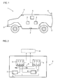
- Fig. 1 shows a vehicle according to the invention 1, here an all-protection transport vehicle (ATF), in which a control device according to the invention is installed.
- ATF all-protection transport vehicle
- Fig. 1 in particular, to take the installation positions of various components, here from various sensors 2 and 3 units, the computing units of the control device included.
- a communication device 4 which may also be understood as a sensor with respect to the present invention.
- the vehicle 1 has a central energy source 5, although other energy sources may also be provided.
- Fig. 1 it can be seen, not only the sensors 2 are arranged distributed, but also the two units 3 are installed spatially spaced, so that in an example occurring weapon hit only one of the units 3 is damaged. Of course, more than two units 3 can be provided.
- the sensors 2 may comprise, for example, GPS sensors, odometers, laser scanners, various types of cameras, radar sensors and / or ultrasound sensors. In the present embodiment, they are provided either redundantly or at least in such a way that there are equivalent sensors that can be used to supply particular functions, for example a plurality of sensors that provide data that are useful for a self-locating function.
- the control device which is described in more detail with regard to the other figures, offers the possibility, as described, of realizing various autonomous and partially autonomous functions.
- a teleoperated Control can be realized, so that a possibility for sensitive operation of operating outside the direct field of vision vehicle is possible.
- An autonomous consequence is also conceivable, ie the possibility of autonomously keeping a defined distance to a tracking object. This can be realized especially when cornering, accelerating and braking the tracking object.
- a so-called waypoint navigation is mentioned, which means that the vehicle can autonomously depart, for example, in GPS coordinates specified waypoints according to the selection of an operator, collisions with emerging obstacles can be avoided and evasive maneuvers can be initiated.
- Such autonomous capabilities or functions are usually realized by the interaction of several algorithms that are implemented modularly by computer programs in the present method, so that, for example, sub-functions that are required by various higher-level functions can be shared and the like.
- An example of such a subfunction is self-localization.
- Algorithms for the autonomous operation of motor vehicles and other vehicles, for example for the realization of the functions mentioned by way of example, are already widely known in the prior art, so that they will not be described here in more detail.
- Fig. 2 shows, in the form of a highly simplified schematic diagram, the basic structure of a control device 6 according to the invention. As already mentioned, it comprises the structural units 3, which are described below with reference to FIG FIG. 3 and FIG. 4 will be explained in more detail and contain computing units 7a, 7b.
- the arithmetic units 7a, 7b of all units 3 together form a decentralized system for the distributed execution of computer programs communicating with each other, whereby the autonomous capabilities can be realized via the provided set of computer programs.
- a middleware is used for communication between the computer programs.
- the exact function of the arithmetic units, in particular with regard to the computer programs, will be described with reference to FIG Fig. 5 be discussed in more detail.
- the basis for being able to perform autonomous functions are the sensors 2 which, as sensor data, provide information about the surroundings of the vehicle 1 to the computer programs on the computing units 7a, 7b, which evaluate these and generate control information for the at least partially autonomous control of the vehicle 1 , which then, as already mentioned, to a drive-by-wire system 8, which is already present in the vehicle 1, are given.
- the two modules 3 each have a separate communication connection to the drive-by-wire system 8.
- drive-by-wire system 8 can also be addressed via one of the communication networks mentioned below or even to be controlled components of the vehicle 1, in particular actuators, such as a motor and / or a robot arm , can be addressed directly, which is also conceivable via one of the second communication networks to be discussed below.
- a communication of the computing units 7a, 7b of the units 3 is necessary.
- this communication between the computing units 7a, 7b is realized by a first communication network 9, which can also be referred to as a middleware network.
- this is a 1 GBit Ethernet, although other configurations, for example as a BUS network, are also conceivable.
- the sensors 2 In order to readably transfer their data via the second communication networks 10a, 10b for the computing units 7a, 7b, the sensors 2 have a signal converter device 11, which is designed to convert measured sensor data into sensor data that can be transmitted via the communication network, provided the sensors can not already provide their own data to the second communication networks 10a, 10b in a suitable manner.
- All communication networks 9, 10a and 10b are wired, with the wiring, as shown Fig. 2 is clearly visible, is guided decentralized, thus forming no central node.
- the cables are routed in different cable channels and different ways are provided for the cables of the various communication networks 9, 10a and 10b.
- each module 3 has common connections 12 for the computing units 7a, 7b contained in it.
- the computing units 7a, 7b recognize this and at least partially a second communication network 10a, 10b is used to communicate the computing units 7a, 7b with one another.
- a priority list which may be stored, for example, in memory devices of the arithmetic units 7a, 7b, can be used to allow a prioritization of communication partners and messages for reducing the data volume. This means, for example, that some uncritical functions (including computer programs) are deactivated, while important functionalities continue to be available.
- Fig. 3 shows the structure of the units 3 closer.
- arithmetic units 7a, 7b here computer, arranged.
- Two of these arithmetic units 7a, 7b are master arithmetic units 7a, two more of these arithmetic units are slave arithmetic units 7b.
- the master processing units 7a include a memory device 14 as a bootable hard drive, such as an SSD, so that they are therefore able to boot itself.
- the slave arithmetic units 7b comprise only a volatile memory 15 (RAM) so that they are provided with an operating system and the set of computer programs after booting the master arithmetic units 7a. In this way, each arithmetic unit 7a, 7b is for executing each computer program of the sentence of
- each computer program is present on each arithmetic unit 7a, 7b.
- the slave computing units 7b include a non-volatile memory device on which at least the computer programs are stored.
- each computing device 7a, 7b is provided with the same performance with respect to the computer programs, which the dynamic Assignment of computer programs and the entire system architecture simplified.
- the assembly 3 further comprises two power supplies 16, to each of the power supplies 16 each have a master processing unit 7a and a slave processing unit 7b are connected. So should one of the power supplies 16 fail, it still leaves half of the computing power. Of course, it is also possible, in another embodiment, to design the power supply 16 completely redundantly, so that all the computing units 7a, 7b of an assembly 3 can be supplied by the power supply 16. In the case of both power supplies 16, these are voltage conversion devices which are connected via a common connection 17 of the assembly 3, cf. Fig. 4 to be supplied.
- Each module 3 is further provided with terminals for further communication links, for example with respect to sensors 2 not provided with signal converter devices 11.
- RS232 interfaces 18 and CAN bus connections 19 are provided.
- the common connections of the unit 3 are also in the in Fig. 4 to take shown back view. It can also be seen there that the housing 13 of the assembly 3 has a cover 24, via which access to the components located inside the housing can be obtained. It should be noted that MIL connectors are always used for the connectors.
- the software consists of a set of computer programs, which in the present case also have defined interfaces for data exchange, so that on the one hand problem-free communication of the
- a specific computer program for reading the sensor data can be created for these sensors, which then communicates this data in standard format to the other computer programs.
- the software is therefore modular and communicates in the present case via a middleware. It is composed of various individual computer programs, which receive the necessary information at the respective start by data retrieval via the middleware or by the configuration files to be discussed in more detail in order to fully utilize the current platform of the vehicle 1. This is now with regard to Fig. 5 explained in more detail.
- a master computer program 20 is first started on each arithmetic unit 7a, 7b, which can also be referred to as the main software module.
- This master computer program now reads from various configuration files 21 (although an implementation is conceivable in which only a single configuration file 21 is present) various information.
- the configuration files 21 are embodied here as XML files.
- a configuration file 21 is provided for the control device 6 itself, another configuration file 21 contains information about the platform (communication interface, available platform data, latencies, dimensions of the platform, dynamic and static limits of the platform, etc.).
- a third configuration file 21 contains the description of the existing sensors 2, for example their type, communication interface, installation position and the like.
- a configuration file 21 is provided for describing the existing computer programs in which every computer program contained in the set of computer programs is registered.
- the master computer program 20 now communicates, cf. Arrows 22, with the other master computer programs and agrees with these, on which arithmetic unit 7a, 7b which computer program should run in order to ensure a uniform utilization of the CPUs and to be able to react directly to any hardware failures.
- the individual computer programs to be started are assigned to the various arithmetic units 7a, 7b, wherein a standard distribution is already defined in the configuration file 21 when the control device 6 is fully functional.
- a master computer program 20 determines that another computer program, a sensor 2 or a computing unit 7a, 7b has failed, then a re-vote between the master computer programs 20 takes place in order to be able to respond to the error, with a new Assignment of computer programs to the remaining resources, that is, computing units 7a, 7b, and / or a targeted shutdown of individual, no longer working or needed computer programs can be done. It can be provided that a priority list is provided in the configuration files 21 for this case, which specifies the measures in case of error at least partially, but advantageously it is also possible that, if for an existing situation no division of computer programs on computer units 7a, 7b is defined, automatically such a division is generated.
- the master computer program 20 thus starts, as exemplarily explained by the computer programs 23, certain computer programs, by way of example a number of computer programs 23 in FIG Fig. 5 However, it monitors these computer programs 23 as part of a watchdog functionality in terms of their behavior. In this case, the master computer program 20, for example, turn off computer programs 23, restart or run with other parameters, such as a lower update rate.
- the sensors 2 since all the sensors 2 communicate directly or indirectly via Ethernet with the arithmetic units 7a, 7b and the communication in the configuration files 21 is fixed, the sensors 2 can simply be exchanged, replaced and expanded if necessary without a complex adaptation of the computer programs is required. Only in the configuration files 21 an adjustment must be made.
Applications Claiming Priority (1)
| Application Number | Priority Date | Filing Date | Title |
|---|---|---|---|
| DE102011117116.2A DE102011117116B4 (de) | 2011-10-27 | 2011-10-27 | Steuereinrichtung zum wenigstens teilweise autonomen Betrieb eines Fahrzeugs und Fahrzeug mit solch einer Steuereinrichtung |
Publications (3)
| Publication Number | Publication Date |
|---|---|
| EP2587330A2 true EP2587330A2 (fr) | 2013-05-01 |
| EP2587330A3 EP2587330A3 (fr) | 2017-03-08 |
| EP2587330B1 EP2587330B1 (fr) | 2019-07-31 |
Family
ID=47172200
Family Applications (1)
| Application Number | Title | Priority Date | Filing Date |
|---|---|---|---|
| EP12006935.6A Active EP2587330B1 (fr) | 2011-10-27 | 2012-10-06 | Dispositif de commande pour le fonctionnement autonome -au moins en partie- d'un véhicule et véhicule équipé d'un tel dispositif de commande |
Country Status (2)
| Country | Link |
|---|---|
| EP (1) | EP2587330B1 (fr) |
| DE (1) | DE102011117116B4 (fr) |
Cited By (11)
| Publication number | Priority date | Publication date | Assignee | Title |
|---|---|---|---|---|
| WO2015155133A1 (fr) * | 2014-04-09 | 2015-10-15 | Continental Teves Ag & Co. Ohg | Système de guidage de véhicule autonome et véhicule à moteur |
| FR3031406A1 (fr) * | 2015-01-05 | 2016-07-08 | Valeo Schalter & Sensoren Gmbh | Architecture pour systeme d'aide a la conduite a automatisation conditionnelle |
| US10234861B2 (en) | 2016-07-19 | 2019-03-19 | Ford Global Technologies, Llc | Autonomous vehicle workload allocation |
| WO2019055442A1 (fr) * | 2017-09-14 | 2019-03-21 | Uber Technologies, Inc. | Commande à tolérance de panne d'un véhicule autonome à multiples voies de commande |
| CN111252079A (zh) * | 2020-03-11 | 2020-06-09 | 中国第一汽车股份有限公司 | 一种驻车冗余控制方法、自动驾驶系统和驾驶设备 |
| CN111386218A (zh) * | 2017-09-29 | 2020-07-07 | 标致雪铁龙汽车股份有限公司 | 用于在网络故障期间辅助驾驶车辆的方法及相关系统 |
| WO2020254120A1 (fr) * | 2019-06-17 | 2020-12-24 | Knorr-Bremse Systeme für Nutzfahrzeuge GmbH | Dispositif et procédé pour la mise en œuvre d'au moins une fonction de véhicule pour un véhicule |
| CN112596370A (zh) * | 2020-12-10 | 2021-04-02 | 北京天地玛珂电液控制系统有限公司 | 供液控制系统 |
| CN113353093A (zh) * | 2021-08-10 | 2021-09-07 | 北汽福田汽车股份有限公司 | 车辆的控制方法、装置和车辆 |
| CN114326688A (zh) * | 2022-01-07 | 2022-04-12 | 中国人民解放军火箭军工程大学 | 一种基于感知响应机制的应急保障专家系统与方法 |
| RU2773970C1 (ru) * | 2018-07-16 | 2022-06-14 | Ниссан Мотор Ко., Лтд. | Способ управления и система управления транспортным средством с содействием при вождении |
Families Citing this family (7)
| Publication number | Priority date | Publication date | Assignee | Title |
|---|---|---|---|---|
| JP6650242B2 (ja) | 2015-10-16 | 2020-02-19 | 日立オートモティブシステムズ株式会社 | 自動運転システム、自動運転制御方法、データecuおよび自動運転ecu |
| DE102015222605A1 (de) | 2015-11-17 | 2017-05-18 | MAN Trucks & Bus AG | Verfahren und Vorrichtung zum assistierten, teilautomatisierten, hochautomatisierten, vollautomatisierten oder fahrerlosen Fahren eines Kraftfahrzeuges |
| US10346152B2 (en) | 2016-09-20 | 2019-07-09 | At&T Intellectual Property I, L.P. | Facilitating use of a universal integrated circuit card (UICC) for secure device updates |
| DE102016220197A1 (de) * | 2016-10-17 | 2018-04-19 | Robert Bosch Gmbh | Verfahren zum Verarbeiten von Daten für ein automatisiertes Fahrzeug |
| DE102017218898A1 (de) | 2017-10-23 | 2019-04-25 | Volkswagen Aktiengesellschaft | Kontrollsystem für ein Batteriesystem |
| WO2021232316A1 (fr) * | 2020-05-20 | 2021-11-25 | 华为技术有限公司 | Système et dispositif de commande électronique redondante |
| CN117647925B (zh) * | 2024-01-30 | 2024-04-09 | 成都正扬博创电子技术有限公司 | 一种多余度飞控计算方法、装置、设备及存储介质 |
Family Cites Families (20)
| Publication number | Priority date | Publication date | Assignee | Title |
|---|---|---|---|---|
| JP3195883B2 (ja) | 1994-10-06 | 2001-08-06 | 三菱電機株式会社 | 車載用通信網及び車載用制御装置 |
| US5691980A (en) | 1995-06-07 | 1997-11-25 | General Electric Company | Local communication network for power reduction and enhanced reliability in a multiple node tracking system |
| US5809220A (en) | 1995-07-20 | 1998-09-15 | Raytheon Company | Fault tolerant distributed control system |
| DE19625002B4 (de) | 1996-06-22 | 2005-03-10 | Daimler Chrysler Ag | Fahrzeugkommunikationssystem |
| KR20010041181A (ko) | 1998-02-19 | 2001-05-15 | 벨 론 이. | 고성능 차량 레이더 시스템 |
| US6263269B1 (en) | 1998-12-23 | 2001-07-17 | International Truck And Engine Corporation | Configuration programming of input/output connections for network modules in a multiplexed vehicle communication system |
| US7020076B1 (en) * | 1999-10-26 | 2006-03-28 | California Institute Of Technology | Fault-tolerant communication channel structures |
| US6633800B1 (en) | 2001-01-31 | 2003-10-14 | Ainsworth Inc. | Remote control system |
| DE10142408A1 (de) * | 2001-08-31 | 2003-04-03 | Bosch Gmbh Robert | Verfahren und Versorgungsleitungstruktur zur Übertragung von Informationen zwischen elektrischen Kraftfahrzeugkomponenten |
| DE10248456A1 (de) * | 2001-10-19 | 2003-06-18 | Denso Corp | Fahrzeugkommunikationssystem |
| JP4483694B2 (ja) | 2004-06-22 | 2010-06-16 | 株式会社デンソー | 車両用通信システム |
| EP2177413B1 (fr) | 2004-07-15 | 2015-02-25 | Hitachi, Ltd. | Système de commande de véhicule |
| JP2006142994A (ja) | 2004-11-19 | 2006-06-08 | Denso Corp | 車両用ネットワークシステムおよび電子制御装置 |
| DE102005010476A1 (de) * | 2005-03-04 | 2006-09-07 | Daimlerchrysler Ag | Steuergerät mit konfigurierbaren Hardwaremodulen |
| US20060253726A1 (en) * | 2005-05-06 | 2006-11-09 | Vikas Kukshya | Fault-tolerant architecture for a distributed control system |
| DE112006003044T5 (de) * | 2005-10-21 | 2008-10-23 | Deere & Company, Moline | Vielseitiges Robotersteuermodul |
| US8538608B2 (en) | 2009-09-09 | 2013-09-17 | General Electric Company | Control system and method for remotely isolating powered units in a rail vehicle system |
| US8126642B2 (en) * | 2008-10-24 | 2012-02-28 | Gray & Company, Inc. | Control and systems for autonomously driven vehicles |
| US8190322B2 (en) | 2009-01-13 | 2012-05-29 | GM Global Technology Operations LLC | Autonomous vehicle maintenance and repair system |
| DE102011003345A1 (de) | 2011-01-28 | 2012-08-02 | Continental Teves Ag & Co. Ohg | Netzwerkverbundsystem für Fahrzeugsteuergeräte und/oder für Fahrzeugregelgeräte und Synchronisationsverfahren zum Betrieb des Netzwerkverbundsystems |
-
2011
- 2011-10-27 DE DE102011117116.2A patent/DE102011117116B4/de active Active
-
2012
- 2012-10-06 EP EP12006935.6A patent/EP2587330B1/fr active Active
Non-Patent Citations (1)
| Title |
|---|
| None |
Cited By (18)
| Publication number | Priority date | Publication date | Assignee | Title |
|---|---|---|---|---|
| WO2015155133A1 (fr) * | 2014-04-09 | 2015-10-15 | Continental Teves Ag & Co. Ohg | Système de guidage de véhicule autonome et véhicule à moteur |
| FR3031406A1 (fr) * | 2015-01-05 | 2016-07-08 | Valeo Schalter & Sensoren Gmbh | Architecture pour systeme d'aide a la conduite a automatisation conditionnelle |
| WO2016110464A1 (fr) * | 2015-01-05 | 2016-07-14 | Valeo Schalter Und Sensoren Gmbh | Architecture pour système d'aide à la conduite à automatisation conditionnelle |
| CN107428247A (zh) * | 2015-01-05 | 2017-12-01 | 法雷奥开关和传感器有限责任公司 | 用于具有附条件自动的驾驶辅助系统的架构 |
| US10234861B2 (en) | 2016-07-19 | 2019-03-19 | Ford Global Technologies, Llc | Autonomous vehicle workload allocation |
| US11307579B2 (en) | 2017-09-14 | 2022-04-19 | Uatc, Llc | Fault-tolerant control of an autonomous vehicle with multiple control lanes |
| WO2019055442A1 (fr) * | 2017-09-14 | 2019-03-21 | Uber Technologies, Inc. | Commande à tolérance de panne d'un véhicule autonome à multiples voies de commande |
| EP4235333A3 (fr) * | 2017-09-14 | 2024-01-17 | Uatc, Llc | Commande à tolérance de panne d'un véhicule autonome à multiples voies de commande |
| US11009874B2 (en) | 2017-09-14 | 2021-05-18 | Uatc, Llc | Fault-tolerant control of an autonomous vehicle with multiple control lanes |
| CN111386218A (zh) * | 2017-09-29 | 2020-07-07 | 标致雪铁龙汽车股份有限公司 | 用于在网络故障期间辅助驾驶车辆的方法及相关系统 |
| RU2773970C1 (ru) * | 2018-07-16 | 2022-06-14 | Ниссан Мотор Ко., Лтд. | Способ управления и система управления транспортным средством с содействием при вождении |
| WO2020254120A1 (fr) * | 2019-06-17 | 2020-12-24 | Knorr-Bremse Systeme für Nutzfahrzeuge GmbH | Dispositif et procédé pour la mise en œuvre d'au moins une fonction de véhicule pour un véhicule |
| CN111252079A (zh) * | 2020-03-11 | 2020-06-09 | 中国第一汽车股份有限公司 | 一种驻车冗余控制方法、自动驾驶系统和驾驶设备 |
| CN112596370A (zh) * | 2020-12-10 | 2021-04-02 | 北京天地玛珂电液控制系统有限公司 | 供液控制系统 |
| CN113353093B (zh) * | 2021-08-10 | 2021-12-10 | 北汽福田汽车股份有限公司 | 车辆的控制方法、装置和车辆 |
| CN113353093A (zh) * | 2021-08-10 | 2021-09-07 | 北汽福田汽车股份有限公司 | 车辆的控制方法、装置和车辆 |
| CN114326688A (zh) * | 2022-01-07 | 2022-04-12 | 中国人民解放军火箭军工程大学 | 一种基于感知响应机制的应急保障专家系统与方法 |
| CN114326688B (zh) * | 2022-01-07 | 2023-07-04 | 中国人民解放军火箭军工程大学 | 一种基于感知响应机制的应急保障专家系统与方法 |
Also Published As
| Publication number | Publication date |
|---|---|
| DE102011117116B4 (de) | 2014-02-13 |
| EP2587330B1 (fr) | 2019-07-31 |
| DE102011117116A1 (de) | 2013-05-02 |
| EP2587330A3 (fr) | 2017-03-08 |
Similar Documents
| Publication | Publication Date | Title |
|---|---|---|
| EP2587330B1 (fr) | Dispositif de commande pour le fonctionnement autonome -au moins en partie- d'un véhicule et véhicule équipé d'un tel dispositif de commande | |
| DE102012102173B4 (de) | Re-konfigurierbare Schnittstellen-basierende elektrische Architektur | |
| EP3584140B1 (fr) | Procédé et dispositif de commande d'un processus de sécurité ainsi que véhicule | |
| DE112013001597T5 (de) | Planung und Überwachung von Autonomen-Mission | |
| DE112006003044T5 (de) | Vielseitiges Robotersteuermodul | |
| DE112014002675T5 (de) | Optimierte Spannungsversorgungsarchitektur | |
| WO2018077518A1 (fr) | Procédé de fonctionnement d'un réseau de bord | |
| WO2021089307A1 (fr) | Dispositif de commande d'une opération de conduite automatisée d'un véhicule | |
| DE102017208462A1 (de) | Verfahren und Vorrichtung zum Ermitteln von Betriebsdaten für ein automatisiertes Fahrzeug | |
| DE112019004377T5 (de) | Verfahren und Steuervorrichtung zum Konfigurieren eines Fahrzeugs | |
| DE102005008556A1 (de) | Steuervorrichtung für Flugzeuge | |
| WO2004077180A1 (fr) | Appareil de commande et commande d'une unite d'entrainement d'un vehicule | |
| EP3607701B1 (fr) | Attribution de ressources numériques dans un réseau informatique modulaire local (edge cloud) | |
| DE102022100797A1 (de) | Sicherheitsvorrichtung und Sicherheitsverfahren zur Überwachung einer Maschine | |
| WO2008077358A1 (fr) | Appareillage doté d'un appareil d'automatisation et d'un appareil de commande, et procédé d'exploitation d'un tel appareillage | |
| EP2587378B1 (fr) | Procédé de fonctionnement d'un dispositif de commande pour la commande au moins en partie autonome d'un véhicule automobile et dispositif de commande pour la réalisation d'un tel procédé | |
| DE102016203966A1 (de) | Steuereinheit und Verfahren zur Ansteuerung von zumindest einem Aktuator eines Fahrzeugs | |
| DE102019132428A1 (de) | Funktionsorientierte Elektronik-Architektur | |
| DE102019220162A1 (de) | Verfahren zur dynamischen kontextbasierten Verteilung von Software in einem Steuerungssystem eines Fahrzeugs sowie ein Steuerungssystem | |
| EP2707998B1 (fr) | Véhicule automobile équipé de deux composants électroniques fournissant une fonction du véhicule et procédé de fonctionnement associé | |
| DE112020007774T5 (de) | Fahrzeugsteuersystem | |
| DE102019134872B4 (de) | Verbesserung der Betriebsparameter eines Rechensystems im Fahrzeug | |
| DE102023200911B3 (de) | Verfahren sowie Assistenzsystem zum Steuern eines Fahrzeuges | |
| DE112022001622T5 (de) | 6fahrzeugsteuervorrichtung und fahrzeugsteuersystem | |
| WO2023227300A1 (fr) | Dispositif d'adaptation pour faire fonctionner automatiquement un véhicule par conversion |
Legal Events
| Date | Code | Title | Description |
|---|---|---|---|
| PUAI | Public reference made under article 153(3) epc to a published international application that has entered the european phase |
Free format text: ORIGINAL CODE: 0009012 |
|
| AK | Designated contracting states |
Kind code of ref document: A2 Designated state(s): AL AT BE BG CH CY CZ DE DK EE ES FI FR GB GR HR HU IE IS IT LI LT LU LV MC MK MT NL NO PL PT RO RS SE SI SK SM TR |
|
| AX | Request for extension of the european patent |
Extension state: BA ME |
|
| PUAL | Search report despatched |
Free format text: ORIGINAL CODE: 0009013 |
|
| AK | Designated contracting states |
Kind code of ref document: A3 Designated state(s): AL AT BE BG CH CY CZ DE DK EE ES FI FR GB GR HR HU IE IS IT LI LT LU LV MC MK MT NL NO PL PT RO RS SE SI SK SM TR |
|
| AX | Request for extension of the european patent |
Extension state: BA ME |
|
| RIC1 | Information provided on ipc code assigned before grant |
Ipc: G05D 1/00 20060101AFI20170202BHEP |
|
| RAP1 | Party data changed (applicant data changed or rights of an application transferred) |
Owner name: DIEHL DEFENCE GMBH & CO. KG |
|
| STAA | Information on the status of an ep patent application or granted ep patent |
Free format text: STATUS: REQUEST FOR EXAMINATION WAS MADE |
|
| 17P | Request for examination filed |
Effective date: 20170908 |
|
| RBV | Designated contracting states (corrected) |
Designated state(s): AL AT BE BG CH CY CZ DE DK EE ES FI FR GB GR HR HU IE IS IT LI LT LU LV MC MK MT NL NO PL PT RO RS SE SI SK SM TR |
|
| GRAP | Despatch of communication of intention to grant a patent |
Free format text: ORIGINAL CODE: EPIDOSNIGR1 |
|
| STAA | Information on the status of an ep patent application or granted ep patent |
Free format text: STATUS: GRANT OF PATENT IS INTENDED |
|
| RIC1 | Information provided on ipc code assigned before grant |
Ipc: B60W 50/00 20060101ALI20190123BHEP Ipc: G05D 1/00 20060101AFI20190123BHEP Ipc: B60W 50/023 20120101ALI20190123BHEP |
|
| INTG | Intention to grant announced |
Effective date: 20190227 |
|
| GRAS | Grant fee paid |
Free format text: ORIGINAL CODE: EPIDOSNIGR3 |
|
| GRAA | (expected) grant |
Free format text: ORIGINAL CODE: 0009210 |
|
| STAA | Information on the status of an ep patent application or granted ep patent |
Free format text: STATUS: THE PATENT HAS BEEN GRANTED |
|
| RBV | Designated contracting states (corrected) |
Designated state(s): AL AT BE BG CH CY CZ DK EE ES FI FR GB GR HR HU IE IS IT LI LT LU LV MC MK MT NL NO PL PT RO RS SE SI SK SM TR |
|
| REG | Reference to a national code |
Ref country code: DE Ref legal event code: R108 |
|
| AK | Designated contracting states |
Kind code of ref document: B1 Designated state(s): AL AT BE BG CH CY CZ DK EE ES FI FR GB GR HR HU IE IS IT LI LT LU LV MC MK MT NL NO PL PT RO RS SE SI SK SM TR |
|
| REG | Reference to a national code |
Ref country code: CH Ref legal event code: EP Ref country code: GB Ref legal event code: FG4D Free format text: NOT ENGLISH |
|
| REG | Reference to a national code |
Ref country code: AT Ref legal event code: REF Ref document number: 1161578 Country of ref document: AT Kind code of ref document: T Effective date: 20190815 |
|
| REG | Reference to a national code |
Ref country code: IE Ref legal event code: FG4D Free format text: LANGUAGE OF EP DOCUMENT: GERMAN |
|
| REG | Reference to a national code |
Ref country code: EE Ref legal event code: FG4A Ref document number: E018000 Country of ref document: EE Effective date: 20190823 |
|
| REG | Reference to a national code |
Ref country code: NL Ref legal event code: MP Effective date: 20190731 |
|
| REG | Reference to a national code |
Ref country code: LT Ref legal event code: MG4D |
|
| PG25 | Lapsed in a contracting state [announced via postgrant information from national office to epo] |
Ref country code: PT Free format text: LAPSE BECAUSE OF FAILURE TO SUBMIT A TRANSLATION OF THE DESCRIPTION OR TO PAY THE FEE WITHIN THE PRESCRIBED TIME-LIMIT Effective date: 20191202 Ref country code: NO Free format text: LAPSE BECAUSE OF FAILURE TO SUBMIT A TRANSLATION OF THE DESCRIPTION OR TO PAY THE FEE WITHIN THE PRESCRIBED TIME-LIMIT Effective date: 20191031 Ref country code: FI Free format text: LAPSE BECAUSE OF FAILURE TO SUBMIT A TRANSLATION OF THE DESCRIPTION OR TO PAY THE FEE WITHIN THE PRESCRIBED TIME-LIMIT Effective date: 20190731 Ref country code: LT Free format text: LAPSE BECAUSE OF FAILURE TO SUBMIT A TRANSLATION OF THE DESCRIPTION OR TO PAY THE FEE WITHIN THE PRESCRIBED TIME-LIMIT Effective date: 20190731 Ref country code: HR Free format text: LAPSE BECAUSE OF FAILURE TO SUBMIT A TRANSLATION OF THE DESCRIPTION OR TO PAY THE FEE WITHIN THE PRESCRIBED TIME-LIMIT Effective date: 20190731 Ref country code: NL Free format text: LAPSE BECAUSE OF FAILURE TO SUBMIT A TRANSLATION OF THE DESCRIPTION OR TO PAY THE FEE WITHIN THE PRESCRIBED TIME-LIMIT Effective date: 20190731 Ref country code: BG Free format text: LAPSE BECAUSE OF FAILURE TO SUBMIT A TRANSLATION OF THE DESCRIPTION OR TO PAY THE FEE WITHIN THE PRESCRIBED TIME-LIMIT Effective date: 20191031 Ref country code: SE Free format text: LAPSE BECAUSE OF FAILURE TO SUBMIT A TRANSLATION OF THE DESCRIPTION OR TO PAY THE FEE WITHIN THE PRESCRIBED TIME-LIMIT Effective date: 20190731 |
|
| PG25 | Lapsed in a contracting state [announced via postgrant information from national office to epo] |
Ref country code: GR Free format text: LAPSE BECAUSE OF FAILURE TO SUBMIT A TRANSLATION OF THE DESCRIPTION OR TO PAY THE FEE WITHIN THE PRESCRIBED TIME-LIMIT Effective date: 20191101 Ref country code: LV Free format text: LAPSE BECAUSE OF FAILURE TO SUBMIT A TRANSLATION OF THE DESCRIPTION OR TO PAY THE FEE WITHIN THE PRESCRIBED TIME-LIMIT Effective date: 20190731 Ref country code: AL Free format text: LAPSE BECAUSE OF FAILURE TO SUBMIT A TRANSLATION OF THE DESCRIPTION OR TO PAY THE FEE WITHIN THE PRESCRIBED TIME-LIMIT Effective date: 20190731 Ref country code: IS Free format text: LAPSE BECAUSE OF FAILURE TO SUBMIT A TRANSLATION OF THE DESCRIPTION OR TO PAY THE FEE WITHIN THE PRESCRIBED TIME-LIMIT Effective date: 20191130 Ref country code: RS Free format text: LAPSE BECAUSE OF FAILURE TO SUBMIT A TRANSLATION OF THE DESCRIPTION OR TO PAY THE FEE WITHIN THE PRESCRIBED TIME-LIMIT Effective date: 20190731 Ref country code: ES Free format text: LAPSE BECAUSE OF FAILURE TO SUBMIT A TRANSLATION OF THE DESCRIPTION OR TO PAY THE FEE WITHIN THE PRESCRIBED TIME-LIMIT Effective date: 20190731 |
|
| PG25 | Lapsed in a contracting state [announced via postgrant information from national office to epo] |
Ref country code: TR Free format text: LAPSE BECAUSE OF FAILURE TO SUBMIT A TRANSLATION OF THE DESCRIPTION OR TO PAY THE FEE WITHIN THE PRESCRIBED TIME-LIMIT Effective date: 20190731 |
|
| PLBI | Opposition filed |
Free format text: ORIGINAL CODE: 0009260 |
|
| PG25 | Lapsed in a contracting state [announced via postgrant information from national office to epo] |
Ref country code: RO Free format text: LAPSE BECAUSE OF FAILURE TO SUBMIT A TRANSLATION OF THE DESCRIPTION OR TO PAY THE FEE WITHIN THE PRESCRIBED TIME-LIMIT Effective date: 20190731 Ref country code: PL Free format text: LAPSE BECAUSE OF FAILURE TO SUBMIT A TRANSLATION OF THE DESCRIPTION OR TO PAY THE FEE WITHIN THE PRESCRIBED TIME-LIMIT Effective date: 20190731 Ref country code: DK Free format text: LAPSE BECAUSE OF FAILURE TO SUBMIT A TRANSLATION OF THE DESCRIPTION OR TO PAY THE FEE WITHIN THE PRESCRIBED TIME-LIMIT Effective date: 20190731 |
|
| 26 | Opposition filed |
Opponent name: RHEINMETALL LANDSYSTEME GMBH Effective date: 20200422 |
|
| PG25 | Lapsed in a contracting state [announced via postgrant information from national office to epo] |
Ref country code: CZ Free format text: LAPSE BECAUSE OF FAILURE TO SUBMIT A TRANSLATION OF THE DESCRIPTION OR TO PAY THE FEE WITHIN THE PRESCRIBED TIME-LIMIT Effective date: 20190731 Ref country code: SM Free format text: LAPSE BECAUSE OF FAILURE TO SUBMIT A TRANSLATION OF THE DESCRIPTION OR TO PAY THE FEE WITHIN THE PRESCRIBED TIME-LIMIT Effective date: 20190731 Ref country code: SK Free format text: LAPSE BECAUSE OF FAILURE TO SUBMIT A TRANSLATION OF THE DESCRIPTION OR TO PAY THE FEE WITHIN THE PRESCRIBED TIME-LIMIT Effective date: 20190731 Ref country code: IS Free format text: LAPSE BECAUSE OF FAILURE TO SUBMIT A TRANSLATION OF THE DESCRIPTION OR TO PAY THE FEE WITHIN THE PRESCRIBED TIME-LIMIT Effective date: 20200224 Ref country code: MC Free format text: LAPSE BECAUSE OF FAILURE TO SUBMIT A TRANSLATION OF THE DESCRIPTION OR TO PAY THE FEE WITHIN THE PRESCRIBED TIME-LIMIT Effective date: 20190731 |
|
| REG | Reference to a national code |
Ref country code: CH Ref legal event code: PL |
|
| PLAX | Notice of opposition and request to file observation + time limit sent |
Free format text: ORIGINAL CODE: EPIDOSNOBS2 |
|
| PG2D | Information on lapse in contracting state deleted |
Ref country code: IS |
|
| PG25 | Lapsed in a contracting state [announced via postgrant information from national office to epo] |
Ref country code: CH Free format text: LAPSE BECAUSE OF NON-PAYMENT OF DUE FEES Effective date: 20191031 Ref country code: LI Free format text: LAPSE BECAUSE OF NON-PAYMENT OF DUE FEES Effective date: 20191031 Ref country code: LU Free format text: LAPSE BECAUSE OF NON-PAYMENT OF DUE FEES Effective date: 20191006 Ref country code: IS Free format text: LAPSE BECAUSE OF FAILURE TO SUBMIT A TRANSLATION OF THE DESCRIPTION OR TO PAY THE FEE WITHIN THE PRESCRIBED TIME-LIMIT Effective date: 20191030 |
|
| REG | Reference to a national code |
Ref country code: BE Ref legal event code: MM Effective date: 20191031 |
|
| PG25 | Lapsed in a contracting state [announced via postgrant information from national office to epo] |
Ref country code: BE Free format text: LAPSE BECAUSE OF NON-PAYMENT OF DUE FEES Effective date: 20191031 Ref country code: SI Free format text: LAPSE BECAUSE OF FAILURE TO SUBMIT A TRANSLATION OF THE DESCRIPTION OR TO PAY THE FEE WITHIN THE PRESCRIBED TIME-LIMIT Effective date: 20190731 |
|
| PG25 | Lapsed in a contracting state [announced via postgrant information from national office to epo] |
Ref country code: IE Free format text: LAPSE BECAUSE OF NON-PAYMENT OF DUE FEES Effective date: 20191006 |
|
| PLBB | Reply of patent proprietor to notice(s) of opposition received |
Free format text: ORIGINAL CODE: EPIDOSNOBS3 |
|
| REG | Reference to a national code |
Ref country code: AT Ref legal event code: MM01 Ref document number: 1161578 Country of ref document: AT Kind code of ref document: T Effective date: 20191006 |
|
| PG25 | Lapsed in a contracting state [announced via postgrant information from national office to epo] |
Ref country code: AT Free format text: LAPSE BECAUSE OF NON-PAYMENT OF DUE FEES Effective date: 20191006 |
|
| PG25 | Lapsed in a contracting state [announced via postgrant information from national office to epo] |
Ref country code: CY Free format text: LAPSE BECAUSE OF FAILURE TO SUBMIT A TRANSLATION OF THE DESCRIPTION OR TO PAY THE FEE WITHIN THE PRESCRIBED TIME-LIMIT Effective date: 20190731 |
|
| PG25 | Lapsed in a contracting state [announced via postgrant information from national office to epo] |
Ref country code: HU Free format text: LAPSE BECAUSE OF FAILURE TO SUBMIT A TRANSLATION OF THE DESCRIPTION OR TO PAY THE FEE WITHIN THE PRESCRIBED TIME-LIMIT; INVALID AB INITIO Effective date: 20121006 Ref country code: MT Free format text: LAPSE BECAUSE OF FAILURE TO SUBMIT A TRANSLATION OF THE DESCRIPTION OR TO PAY THE FEE WITHIN THE PRESCRIBED TIME-LIMIT Effective date: 20190731 |
|
| PLCK | Communication despatched that opposition was rejected |
Free format text: ORIGINAL CODE: EPIDOSNREJ1 |
|
| APBM | Appeal reference recorded |
Free format text: ORIGINAL CODE: EPIDOSNREFNO |
|
| APBP | Date of receipt of notice of appeal recorded |
Free format text: ORIGINAL CODE: EPIDOSNNOA2O |
|
| APAH | Appeal reference modified |
Free format text: ORIGINAL CODE: EPIDOSCREFNO |
|
| APBQ | Date of receipt of statement of grounds of appeal recorded |
Free format text: ORIGINAL CODE: EPIDOSNNOA3O |
|
| PG25 | Lapsed in a contracting state [announced via postgrant information from national office to epo] |
Ref country code: MK Free format text: LAPSE BECAUSE OF FAILURE TO SUBMIT A TRANSLATION OF THE DESCRIPTION OR TO PAY THE FEE WITHIN THE PRESCRIBED TIME-LIMIT Effective date: 20190731 |
|
| APAH | Appeal reference modified |
Free format text: ORIGINAL CODE: EPIDOSCREFNO |
|
| PGFP | Annual fee paid to national office [announced via postgrant information from national office to epo] |
Ref country code: GB Payment date: 20231020 Year of fee payment: 12 |
|
| PGFP | Annual fee paid to national office [announced via postgrant information from national office to epo] |
Ref country code: IT Payment date: 20231026 Year of fee payment: 12 Ref country code: FR Payment date: 20231025 Year of fee payment: 12 Ref country code: EE Payment date: 20231018 Year of fee payment: 12 |