EP2587046A2 - Fuel injection valve - Google Patents
Fuel injection valve Download PDFInfo
- Publication number
- EP2587046A2 EP2587046A2 EP11798319.7A EP11798319A EP2587046A2 EP 2587046 A2 EP2587046 A2 EP 2587046A2 EP 11798319 A EP11798319 A EP 11798319A EP 2587046 A2 EP2587046 A2 EP 2587046A2
- Authority
- EP
- European Patent Office
- Prior art keywords
- fuel
- tube
- injection valve
- fuel injection
- peripheral surface
- Prior art date
- Legal status (The legal status is an assumption and is not a legal conclusion. Google has not performed a legal analysis and makes no representation as to the accuracy of the status listed.)
- Granted
Links
Images


Classifications
-
- F—MECHANICAL ENGINEERING; LIGHTING; HEATING; WEAPONS; BLASTING
- F02—COMBUSTION ENGINES; HOT-GAS OR COMBUSTION-PRODUCT ENGINE PLANTS
- F02M—SUPPLYING COMBUSTION ENGINES IN GENERAL WITH COMBUSTIBLE MIXTURES OR CONSTITUENTS THEREOF
- F02M61/00—Fuel-injectors not provided for in groups F02M39/00 - F02M57/00 or F02M67/00
- F02M61/16—Details not provided for in, or of interest apart from, the apparatus of groups F02M61/02 - F02M61/14
- F02M61/18—Injection nozzles, e.g. having valve seats; Details of valve member seated ends, not otherwise provided for
- F02M61/1853—Orifice plates
-
- F—MECHANICAL ENGINEERING; LIGHTING; HEATING; WEAPONS; BLASTING
- F02—COMBUSTION ENGINES; HOT-GAS OR COMBUSTION-PRODUCT ENGINE PLANTS
- F02M—SUPPLYING COMBUSTION ENGINES IN GENERAL WITH COMBUSTIBLE MIXTURES OR CONSTITUENTS THEREOF
- F02M61/00—Fuel-injectors not provided for in groups F02M39/00 - F02M57/00 or F02M67/00
- F02M61/16—Details not provided for in, or of interest apart from, the apparatus of groups F02M61/02 - F02M61/14
- F02M61/18—Injection nozzles, e.g. having valve seats; Details of valve member seated ends, not otherwise provided for
-
- F—MECHANICAL ENGINEERING; LIGHTING; HEATING; WEAPONS; BLASTING
- F02—COMBUSTION ENGINES; HOT-GAS OR COMBUSTION-PRODUCT ENGINE PLANTS
- F02M—SUPPLYING COMBUSTION ENGINES IN GENERAL WITH COMBUSTIBLE MIXTURES OR CONSTITUENTS THEREOF
- F02M2200/00—Details of fuel-injection apparatus, not otherwise provided for
- F02M2200/16—Sealing of fuel injection apparatus not otherwise provided for
Definitions
- the fuel tube made of a relatively soft material such as Teflon tends to be assembled in a state of being misaligned with the fuel injection valve. Accordingly, assembly properties and a fuel leakage are further deteriorated.
- the present invention has been made in view of the above-mentioned problem, and an object thereof is to provide a fuel injection valve capable of preventing a phenomenon in which a residual substance is deposited on a surface of a nozzle of the fuel injection valve while a fuel discharged through a gap between an orifice plate and a fuel tube is evaporated by mounting a tube adaptor for preventing the generation of the gap between the orifice plate and the fuel tube of the fuel injection valve at an end of the fuel injection valve, thereby preventing an area reduction of an injection opening of the nozzle due to the residual substance and poor performance of the fuel injection valve, suppressing life-shortening of the fuel injection valve due to a fuel leakage, enabling an additional device for preventing the fuel leakage to be removed, and enabling vehicle performance to be improved and air pollution to be prevented.
- another object of the present invention is to provide a fuel injection valve capable of generating no gap between the fuel injection valve and a fuel tube by assembling a portion of the fuel tube within the fuel injection valve, and doubly preventing a fuel from leaking by interposing an airtightness maintaining member between the fuel tube and a contact surface of a valve housing.
- a further object of the present invention is to provide a fuel injection valve capable of reducing a manufacturing process or cost of a component for preventing a fuel leakage while actually improving fuel sealing or injection performance without deteriorating the same by compactly producing the component used for doubly preventing the fuel leakage.
- a fuel injection valve for an internal combustion engine includes a needle which moves within a valve housing; a valve seat formed therein with an opening and closing hole which is opened and closed by the needle; an orifice plate which is attached to a lower portion of the valve seat and from which a fuel is injected through an injection hole; a fuel tube being a path through which the fuel injected from the orifice plate is supplied to the internal combustion engine; and a tube adaptor which is installed between the orifice plate and the fuel tube in order to prevent a leakage of the fuel supplied from the orifice plate to the fuel tube.
- the tube adaptor may include an attachment portion which is attached on a lower surface of the orifice plate, and an outer side bent portion which is bent downward at an outer side of the attachment portion.
- the tube adaptor may further include an inner side bent portion which is bent downward at an inner side of the attachment portion.
- the inner side bent portion may be inserted and fixed, at an outer peripheral surface thereof, on an inner peripheral surface of a circular groove formed so as to be connected with a passage of the fuel tube at a central portion of an upper surface of the fuel tube, or the inner side bent portion may be press-fitted, at an inner peripheral surface thereof, to a step formed on an outer peripheral surface of the upper surface of the fuel tube.
- the fuel tube may be provided with a flange portion which is formed to protrude at an upper end of the fuel tube and attached on a lower surface of the orifice plate.
- An outer peripheral surface of the flange portion may be attached on or detached from an inner peripheral surface of the valve housing.
- a sealing member may be interposed on an attachment surface therebetween.
- a surface of the orifice plate may be attached to an inner peripheral surface of the valve housing adjacent to a lower surface of the valve seat.
- the tube adaptor may include an attachment portion which is attached on a lower surface of the valve seat, an outer side bent portion which is bent downward at an outer side of the attachment portion, and an inner side bent portion which protrudes downward at an inner side of the attachment portion so as to be inserted into a passage of the fuel tube and attached on a surface of the passage.
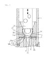
- Fig. 1 is an exploded perspective view illustrating a state of separating a fuel tube from a fuel injection valve according to a first embodiment of the present invention.
- Fig. 8 is a view illustrating a coupled state of a fuel tube to a fuel injection valve according to the related art.
- the valve seat 3 is provided within the valve housing 1.
- the valve seat 3 is formed, at an inner lower end thereof, with a contact surface 31 which is attached on or detached from the closure surface 21a of the ball valve 21.
- the valve seat 3 is formed with an opening and closing hole 32 which is connected from the contact surface 31 to the bottom of the valve seat.
- the orifice plate 4 has a disk shape and is tightly installed at a lower end of the valve seat 3.
- the orifice plate 4 is formed, at a central portion thereof, with an injection hole 41 for measuring and adjusting a flow rate of the fuel during the passing thereof.
- a circular groove 64 is formed at a central portion of an upper surface of the fuel tube 6 so as to correspond to a shape of the inner side bent portion 53 and be connected with the passage 61. Since the outer peripheral surface of the inner side bent portion 53 of the tube adaptor 5 is inserted and fixed to an inner peripheral surface of the circular groove formed at the central portion of the upper surface of the fuel tube 6, the inner side bent portion 53 and the circular groove 64 may be easily coupled by such an insertion manner.
- the fuel tube 6 is a path through which the fuel injected from the injection hole 41 of the orifice plate 4 is supplied to an internal combustion engine (not shown in the drawings).
- the fuel tube 6 is attached, at an upper end thereof, on the lower surface of the orifice plate 4 by the tube adaptor 5 while being connected, at a lower end thereof, to the internal combustion engine.
- the fuel injection valve and the fuel tube 6 may be easily separated from each other for maintenance without the generation of a gap therebetween by the tube adaptor 5.
- the tube adaptor 5a is interposed between the orifice plate 4 and the fuel tube 6 to allow the injection hole 41 of the orifice plate 4 to come into tight contact with the passage 61 of the fuel tube 6 without a gap therebetween. Accordingly, the fuel is prevented from leaking outside the passage 61.
- a step 65 is formed at an upper outer peripheral surface of the fuel tube 6 so as to correspond to an inner diameter shape of the inner side bent portion 53a.
- valve housing contact bent portion 4b is provided at the edge of the orifice plate 4 as described above, the fuel tube 6 is provided in a state in which the flange portion 62 is spaced apart from the inner peripheral surface of the valve housing 1.
- a fuel injection valve As shown in Fig. 5 , a fuel injection valve according to the present embodiment includes a valve housing 1, a needle 2, a valve seat 3, an orifice plate 4, a tube adaptor 5c, and a fuel tube 6. Since each of the valve housing 1, the needle 2, the valve seat 3, and the orifice plate 4 has the same structure and function as the configuration of the first and second embodiments, no description thereof will be given.
- the tube adaptor 5c is located so that an upper surface thereof comes into contact with the lower surface of flange portion 62 of the fuel tube 6.
- a sealing member 63 such as an O-ring is interposed between an outer peripheral surface of the flange portion 62 and the inner peripheral surface of the valve housing 1, thereby preventing the leakage of the fuel.
- the fuel is prevented from leaking outside the passage.
- the outer side bent portion 52c of the tube adaptor 5b is welded and coupled on the inner peripheral surface of the valve housing 1, the fuel is prevented from leaking outside the passage.
- the sealing member 63 provided on the outer peripheral surface of the flange portion 62 of the fuel tube 6.
- the inner side bent portion 53 is again constituted of two portions which are an inclined portion 53-1 and a flat portion 53-2.
- the inclined portion 53-1 has a truncated conical shape so as to be seated along an inclined surface from an upper end corner of the inclined surface of the upper end of the passage 61 to lower end corner which is an ending portion of the inclined surface.
- the flat portion 53-2 is bent at a lower end of the inclined portion 53-1 and evenly extends to be perpendicular to an axis of the passage 61.
Landscapes
- Engineering & Computer Science (AREA)
- Chemical & Material Sciences (AREA)
- Combustion & Propulsion (AREA)
- Mechanical Engineering (AREA)
- General Engineering & Computer Science (AREA)
- Fuel-Injection Apparatus (AREA)
Abstract
Description
- Exemplary embodiments of the present invention relate to a fuel injection valve, and more particularly, to a fuel injection valve for an internal combustion engine which is provided to intensively inject a fuel to a localized area.
- In general, a fuel injection valve referred to as an injector is a device to inject a liquid having a pressure from a nozzle. The nozzle is typically an injection nozzle with a built-in solenoid which allows a fuel to be injected when a fuel pressure reaches a set value by a needle valve in a diesel engine, and to be injected by an injection signal sent from a computer in a gasoline engine. The needle valve is integral with a plunger. Thus, when the injection signal is transferred to the fuel injection valve, a ball valve and a valve shaft, which are integral with the magnetized plunger, are pulled by the injection signal, with the consequence that an injection opening is opened and the fuel is injected at the same time. An injection amount of fuel is determined depending on an open time of the needle valve, namely, an energization time of a solenoid coil.
- In such an existing fuel injection valve, since an end of the fuel injection valve and a passage of a fuel tube are assembled in a butting manner, a coupling tolerance occurs between the assembled components. Accordingly, a gap is generated between the end of the fuel injection valve and the fuel tube due to such a coupling tolerance, and thus there is a case in which a fuel leaks to the outside. That is, as shown in
Fig. 8 , when a coupling tolerance occurs between thefuel tube 106 and anorifice plate 104 which is interposed between a lower surface of avalve seat 103 located at a lower end of the fuel injection valve and an upper end surface of thefuel tube 106, a fuel to be injected into thepassage 161 of thefuel tube 106 leaks outside thefuel tube 106 as indicated by the arrows inFig. 8 . - As such, the fuel leaking to the outside leaves a residual substance on a surface of the fuel injection valve while being evaporated. As such a residual substance deposited on the surface of the fuel injection valve reduces the area of the injection opening of the fuel injection valve, the fuel injection valve has poor performance and a portion of the leaked fuel is discharged outside a vehicle to cause air pollution.
- In addition, since deposits are fixed in the vicinity of the injection opening of the fuel injection valve, cleaning costs are additionally generated to remove the deposits during vehicle maintenance.
- Furthermore, the fuel tube made of a relatively soft material such as Teflon tends to be assembled in a state of being misaligned with the fuel injection valve. Accordingly, assembly properties and a fuel leakage are further deteriorated.
- In addition, when the fuel injected from the fuel injection valve gets out of the passage and is discharged to the outside, there is a problem that vehicle performance such as output and fuel efficiency is also deteriorated.
- Accordingly, the present invention has been made in view of the above-mentioned problem, and an object thereof is to provide a fuel injection valve capable of preventing a phenomenon in which a residual substance is deposited on a surface of a nozzle of the fuel injection valve while a fuel discharged through a gap between an orifice plate and a fuel tube is evaporated by mounting a tube adaptor for preventing the generation of the gap between the orifice plate and the fuel tube of the fuel injection valve at an end of the fuel injection valve, thereby preventing an area reduction of an injection opening of the nozzle due to the residual substance and poor performance of the fuel injection valve, suppressing life-shortening of the fuel injection valve due to a fuel leakage, enabling an additional device for preventing the fuel leakage to be removed, and enabling vehicle performance to be improved and air pollution to be prevented.
- In addition, another object of the present invention is to provide a fuel injection valve capable of generating no gap between the fuel injection valve and a fuel tube by assembling a portion of the fuel tube within the fuel injection valve, and doubly preventing a fuel from leaking by interposing an airtightness maintaining member between the fuel tube and a contact surface of a valve housing.
- In addition, a further object of the present invention is to provide a fuel injection valve capable of reducing a manufacturing process or cost of a component for preventing a fuel leakage while actually improving fuel sealing or injection performance without deteriorating the same by compactly producing the component used for doubly preventing the fuel leakage.
- In accordance with an aspect of the present invention, a fuel injection valve for an internal combustion engine includes a needle which moves within a valve housing; a valve seat formed therein with an opening and closing hole which is opened and closed by the needle; an orifice plate which is attached to a lower portion of the valve seat and from which a fuel is injected through an injection hole; a fuel tube being a path through which the fuel injected from the orifice plate is supplied to the internal combustion engine; and a tube adaptor which is installed between the orifice plate and the fuel tube in order to prevent a leakage of the fuel supplied from the orifice plate to the fuel tube.
- The tube adaptor may include an attachment portion which is attached on a lower surface of the orifice plate, and an outer side bent portion which is bent downward at an outer side of the attachment portion.
- The tube adaptor may further include an inner side bent portion which is bent downward at an inner side of the attachment portion.
- The inner side bent portion may be inserted and fixed, at an outer peripheral surface thereof, on an inner peripheral surface of a circular groove formed so as to be connected with a passage of the fuel tube at a central portion of an upper surface of the fuel tube, or the inner side bent portion may be press-fitted, at an inner peripheral surface thereof, to a step formed on an outer peripheral surface of the upper surface of the fuel tube.
- The fuel tube may be provided with a flange portion which is formed to protrude at an upper end of the fuel tube and attached on a lower surface of the orifice plate.
- An outer peripheral surface of the flange portion may be attached on or detached from an inner peripheral surface of the valve housing.
- When the outer peripheral surface of the flange portion is attached on the inner peripheral surface of the valve housing, a sealing member may be interposed on an attachment surface therebetween.
- When the outer peripheral surface of the flange portion is detached from the inner peripheral surface of the valve housing, a surface of the orifice plate may be attached to an inner peripheral surface of the valve housing adjacent to a lower surface of the valve seat.
- The outer side bent portion of the tube adaptor may be welded and coupled to an inner peripheral surface of the valve housing.
- In accordance with another aspect of the present invention, a fuel injection valve for an internal combustion engine includes a needle which moves within a valve housing; a valve seat formed therein with an opening and closing hole which is opened and closed by the needle; a fuel tube being a path through which the fuel injected from the valve housing is supplied to the internal combustion engine; and a tube adaptor which is interposed between the valve seat and the fuel tube, thereby injecting the fuel through an injection hole and preventing the fuel injected from the injection hole from leaking between the fuel tube and the valve seat.
- The tube adaptor may include an attachment portion which is attached on a lower surface of the valve seat, an outer side bent portion which is bent downward at an outer side of the attachment portion, and an inner side bent portion which protrudes downward at an inner side of the attachment portion so as to be inserted into a passage of the fuel tube and attached on a surface of the passage.
- The inner side bent portion may be formed as a conical inclined portion so that an inner diameter thereof is gradually decreased toward the injection hole.
- The inner side bent portion may have a truncated conical shape which is constituted of an inclined portion which extends along an inclined surface of the passage up to a lower end of the inclined surface of the passage; and a flat portion which extends to be perpendicular to an axis of the passage at a lower end of the inclined portion.
-
Fig. 1 is an exploded perspective view illustrating a state of separating a fuel tube from a fuel injection valve according to a first embodiment of the present invention. -
Fig. 2 is a side cross-sectional view illustrating a coupled state of the fuel tube to the fuel injection valve. -
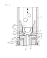
Fig. 3 is a side cross-sectional view illustrating a coupled state of a fuel tube to a fuel injection valve according to a second embodiment of the present invention. -
Fig. 4 is a side cross-sectional view illustrating a coupled state of a fuel tube to a fuel injection valve according to a third embodiment of the present invention. -
Fig. 5 is a side cross-sectional view illustrating a coupled state of a fuel tube to a fuel injection valve according to a fourth embodiment of the present invention. -
Fig. 6 is a side cross-sectional view illustrating a coupled state of a fuel tube to a fuel injection valve according to a fifth embodiment of the present invention. -
Fig. 7 is a side cross-sectional view illustrating a coupled state of a fuel tube to a fuel injection valve according to a sixth embodiment of the present invention. -
Fig. 8 is a view illustrating a coupled state of a fuel tube to a fuel injection valve according to the related art. - Reference will now be made in detail to embodiments of a fuel injection valve of the present invention with reference to the accompanying drawings.
- [First Embodiment]
- As shown in
Figs. 1 and2 , a fuel injection valve according to the present embodiment includes avalve housing 1, aneedle 2, avalve seat 3, anorifice plate 4, atube adaptor 5, and afuel tube 6. - The
needle 2 is installed within a longitudinal opening of thevalve housing 1 so that thevalve housing 1 constitutes a magnetic passage during the energization of a solenoid coil. - The
needle 2 is provided within thevalve housing 1 and moves in a longitudinal direction thereof by an electromagnetic circuit during the application of electric power. Theneedle 2 includes aball valve 21 and avalve shaft 22. - The
ball valve 21 is formed, at a lower surface thereof, with aclosure surface 21a. Thevalve shaft 22 is mutually coupled to an upper end of theball valve 21 by welding and the like, and moves along the longitudinal direction of thevalve housing 1. - The
valve seat 3 is provided within thevalve housing 1. Thevalve seat 3 is formed, at an inner lower end thereof, with acontact surface 31 which is attached on or detached from theclosure surface 21a of theball valve 21. Thevalve seat 3 is formed with an opening andclosing hole 32 which is connected from thecontact surface 31 to the bottom of the valve seat. - In this case, when the closure surface 21a of the
ball valve 21 comes into complete contact with thecontact surface 31 connected with the opening andclosing hole 32, the supply of a fuel stops. On the other hand, when theclosure surface 21a of theball valve 21 is spaced apart from thecontact surface 31, the fuel is supplied. Accordingly, a supply amount of the fuel is adjusted depending on a clearance level of theclosure surface 21a and thecontact surface 31. - The
orifice plate 4 has a disk shape and is tightly installed at a lower end of thevalve seat 3. Theorifice plate 4 is formed, at a central portion thereof, with aninjection hole 41 for measuring and adjusting a flow rate of the fuel during the passing thereof. - Here, although the present embodiment is illustrated in which one
injection hole 41 is formed at the central portion of theorifice plate 4, one injection hole may be formed in a slit shape or a plurality of injection holes may have a hole or slit shape and be formed to be arranged at equal intervals along a circumferential direction of the orifice plate. - As such, when the
injection hole 41 is plurally formed along the circumferential direction, theinjection hole 41 may be located inward of an innerside bent portion 53 of thetube adaptor 5. Theinjection hole 41 may have a significantly decreased diameter by decreasing a thickness of theorifice plate 4 to further promote the atomization of fuel particles. - The
tube adaptor 5 is interposed between theorifice plate 4 and thefuel tube 6 to allow theinjection hole 41 of theorifice plate 4 to come into tight contact with apassage 61 of thefuel tube 6 without a gap therebetween. Accordingly, the fuel is prevented from leaking outside thepassage 61. - In this case, the
tube adaptor 5 includes anattachment portion 51 having a disk shape, an outer side bentportion 52 which is formed to be bent downward at an outer side edge of theattachment portion 51, and an inner sidebent portion 53 by which a hole is defined at a central portion of theattachment portion 51 and which is simultaneously formed to be bent downward at an inner side edge of the hole. - That is, the
tube adaptor 5 has a coupling structure that is constituted of theattachment portion 51 which is inserted into thevalve housing 1 and joined on a lower surface of theorifice plate 4 without interference with theinjection hole 41, the outer side bentportion 52 which is formed to be bent downward at the outer side edge of theattachment portion 51, and the inner sidebent portion 53 which is bent downward at a lower surface of the central portion of theattachment portion 51 to be coupled with thefuel tube 6 while being inserted and fixed, at an outer peripheral surface thereof, to an inner peripheral surface of thepassage 61 of thefuel tube 6. - In particular, since the inner side
bent portion 53 of thetube adaptor 5 is bent downward, acircular groove 64 is formed at a central portion of an upper surface of thefuel tube 6 so as to correspond to a shape of the inner sidebent portion 53 and be connected with thepassage 61. Since the outer peripheral surface of the inner sidebent portion 53 of thetube adaptor 5 is inserted and fixed to an inner peripheral surface of the circular groove formed at the central portion of the upper surface of thefuel tube 6, the inner sidebent portion 53 and thecircular groove 64 may be easily coupled by such an insertion manner. - Furthermore, an outer peripheral surface of the outer side bent
portion 52 of thetube adaptor 5 is welded and coupled on an inner peripheral surface of thevalve housing 1 by heat applied from the outside of thevalve housing 1. - The
fuel tube 6 is a path through which the fuel injected from theinjection hole 41 of theorifice plate 4 is supplied to an internal combustion engine (not shown in the drawings). Thefuel tube 6 is attached, at an upper end thereof, on the lower surface of theorifice plate 4 by thetube adaptor 5 while being connected, at a lower end thereof, to the internal combustion engine. - Therefore, in the embodiment, the fuel injection valve and the
fuel tube 6 may be easily separated from each other for maintenance without the generation of a gap therebetween by thetube adaptor 5. - [Second Embodiment]
- As shown in
Fig. 3 , a fuel injection valve according to the present embodiment includes avalve housing 1, aneedle 2, avalve seat 3, anorifice plate 4, atube adaptor 5a, and afuel tube 6. Since each of thevalve housing 1, theneedle 2, thevalve seat 3, and theorifice plate 4 has the same structure and function as the configuration of the first embodiment, no description thereof will be given. - The
tube adaptor 5a is interposed between theorifice plate 4 and thefuel tube 6 to allow theinjection hole 41 of theorifice plate 4 to come into tight contact with thepassage 61 of thefuel tube 6 without a gap therebetween. Accordingly, the fuel is prevented from leaking outside thepassage 61. - In this case, the
tube adaptor 5a includes anattachment portion 51a having a disk shape, an outer side bentportion 52a which is formed to be bent downward at an outer side edge of theattachment portion 51a, and an inner sidebent portion 53a by which a hole is defined at a central portion of theattachment portion 51a and which is simultaneously formed to be bent downward at an inner side edge of the hole. - Particularly, unlike the first embodiment, the inner side
bent portion 53a is press-fitted, at an inner peripheral surface thereof, on an outer peripheral surface of thefuel tube 6, thereby improving a coupling force with thefuel tube 6. - Since the inner side
bent portion 53a of thetube adaptor 5a is bent downward, astep 65 is formed at an upper outer peripheral surface of thefuel tube 6 so as to correspond to an inner diameter shape of the inner sidebent portion 53a. - In addition, an outer peripheral surface of the outer side bent
portion 52a of thetube adaptor 5a is welded and coupled on the inner peripheral surface of thevalve housing 1 by heat applied from the outside of thevalve housing 1. - Therefore, in the embodiment, since the upper end of the
fuel tube 6 is press-fitted in the fuel injection valve, the fuel injection valve and thefuel tube 6 may be easily separated from each other for maintenance without the generation of a gap therebetween, and have a mutually improved coupling force. - [Third Embodiment]
- As shown in
Fig. 4 , a fuel injection valve according to the present embodiment includes avalve housing 1, aneedle 2, avalve seat 3, anorifice plate 4, atube adaptor 5b, and afuel tube 6. Since each of thevalve housing 1, theneedle 2, and thevalve seat 3 has the same structure and function as the configuration of the first and second embodiments, no description thereof will be given. - The
orifice plate 4 is formed, at a central portion thereof, with aninjection hole 41 for measuring and adjusting a flow rate of the fuel during the passing thereof. Theorifice plate 4 includes a valveseat attachment surface 4a which comes into contact with the lower end of thevalve seat 3, and a valve housing contact bentportion 4b which is formed to be bent downward at an edge of the valveseat attachment surface 4a and is installed to come into tight contact with the inner peripheral surface of thevalve housing 1 adjacent to the lower end of thevalve seat 3. - The
tube adaptor 5b is provided to be attached on a lower surface of aflange portion 62 formed at the upper end of thefuel tube 6 and the inner peripheral surface of thevalve housing 1 and allows theflange portion 62 of thefuel tube 6 to be attached to theorifice plate 4. Accordingly, the fuel is prevented from leaking outside the passage. - Furthermore, the
tube adaptor 5b is formed with a through hole so that an upper surface of thetube adaptor 5b comes into contact with the lower surface of theflange portion 62 of thefuel tube 6 which passes through a central portion of anattachment portion 51a attached on the lower surface of thevalve seat 3. - Since the valve housing contact bent
portion 4b is provided at the edge of theorifice plate 4 as described above, thefuel tube 6 is provided in a state in which theflange portion 62 is spaced apart from the inner peripheral surface of thevalve housing 1. - Therefore, in the embodiment, since the
flange portion 62 formed at the upper end of thefuel tube 6 is assembled in the fuel injection valve, a gap is not generated between the fuel injection valve and thefuel tube 6. - In the embodiment, primarily, since the
flange portion 62 formed at the upper end of thefuel tube 6 is attached to theorifice plate 4 by thetube adaptor 5b, the fuel is prevented from leaking outside the passage. Also, secondarily, since an outer sidebent portion 52b of thetube adaptor 5b is welded and coupled on the inner peripheral surface of thevalve housing 1, the fuel is prevented from leaking outside the passage. - [Fourth Embodiment]
- As shown in
Fig. 5 , a fuel injection valve according to the present embodiment includes avalve housing 1, aneedle 2, avalve seat 3, anorifice plate 4, a tube adaptor 5c, and afuel tube 6. Since each of thevalve housing 1, theneedle 2, thevalve seat 3, and theorifice plate 4 has the same structure and function as the configuration of the first and second embodiments, no description thereof will be given. - The tube adaptor 5c is located so that an upper surface thereof comes into contact with the lower surface of
flange portion 62 of thefuel tube 6. A sealingmember 63 such as an O-ring is interposed between an outer peripheral surface of theflange portion 62 and the inner peripheral surface of thevalve housing 1, thereby preventing the leakage of the fuel. - In this case, the tube adaptor 5c includes an attachment portion 51c having a disk shape, and an outer side
bent portion 52c which is formed to be bent downward at an edge of the attachment portion 51c. The attachment portion 51c is formed, at a central portion thereof, with a through hole through which thefuel tube 6 passes so that an upper surface of the tube adaptor 5c comes into contact with the lower surface of theflange portion 62. - The
fuel tube 6 is provided in a state in which the outer peripheral surface of theflange portion 62 is attached on the inner peripheral surface of thevalve housing 1. Thefuel tube 6 is further provided with the sealingmember 63 such as an O-ring between the outer peripheral surface of theflange portion 62 and the inner peripheral surface of thevalve housing 1. - In the embodiment, primarily, since the
flange portion 62 formed at the upper end of thefuel tube 6 is attached to theorifice plate 4 by thetube adaptor 5b, the fuel is prevented from leaking outside the passage. Secondarily, since the outer sidebent portion 52c of thetube adaptor 5b is welded and coupled on the inner peripheral surface of thevalve housing 1, the fuel is prevented from leaking outside the passage. Thirdly, the fuel is prevented from leaking outside the passage by the sealingmember 63 provided on the outer peripheral surface of theflange portion 62 of thefuel tube 6. - [Fifth Embodiment]
- As shown in
Fig. 6 , a fuel injection valve according to the present embodiment includes aneedle 2, avalve seat 3, afuel tube 6, and atube adaptor 5. Since each of theneedle 2, thevalve seat 3, and thefuel tube 6 has, except for a portion thereof, mostly the same configuration as the first to fourth embodiments, no description thereof will be given. In particular, as shown inFig. 6 , functions of the orifice plates and the tube adaptors of the other embodiments are incorporated in onetube adaptor 5 in the fuel injection valve according to the present embodiment. - The
tube adaptor 5 is interposed between thevalve seat 3 and thefuel tube 6 and injects the fuel through theinjection hole 41, thereby preventing the fuel injected frominjection hole 41 being leaking between thevalve seat 3 and thefuel tube 6. For this reason, as shown inFig. 6 , thetube adaptor 5 is manufactured in a washer shape bending a thin plate, and includes anattachment portion 51, an outer side bentportion 52, and an inner sidebent portion 53. - First, the
attachment portion 51 is a portion attached on the lower surface of thevalve seat 3, similarly to the orifice plates of the above other embodiments. Theattachment portion 51 has a disk shape of a coin form which is circularly recessed at a central portion of theattachment portion 51 due to the inner sidebent portion 53. The outer side bentportion 52 is formed to be bent downward at an outer side edge of theattachment portion 51, similarly to the outer side bent portions of the tube adaptors of the above other embodiments. An outer peripheral surface of the outer side bentportion 52 is welded and coupled on the inner peripheral surface of thevalve housing 1 by heat applied from the outside of thevalve housing 1. Lastly, the inner sidebent portion 53 is formed to be recessed by bending an inner side edge of a circular portion formed at the central portion of theattachment portion 51 in the downward direction. As shown inFig. 6 , the inner sidebent portion 53 is inserted into thepassage 61 of thefuel tube 6 and attached on a passage surface of thepassage 61. Here, the inner sidebent portion 53 may be formed in various shapes, and may be formed in a nozzle shape protruding toward thefuel tube 6 as shown inFig. 6 . In this case, the inner sidebent portion 53 is formed as a conical inclined portion having a tapered shape so that an inner diameter thereof is gradually decreased toward theinjection hole 41 below. - Accordingly, according to the above embodiment, since the tube adaptor and the orifice plate are incorporated as one component, the total number of processes is reduced and thus a cost reduction is realized. Moreover, the
tube adaptor 5 is deeply inserted into thepassage 61 and is automatically aligned to be centered due to conical properties converging on the center. Consequently, the coupling force between the fuel injection valve and thefuel tube 6 is increased and the sealing performance between thetube adaptor 5 and thefuel tube 6 is improved. - [Sixth Embodiment]
- Meanwhile,
Fig. 7 illustrates a fuel injection valve according to the present embodiment. Similarly to the fifth embodiment, functions of the orifice plate and the tube adaptor are incorporated in onetube adaptor 5 in the fuel injection valve according to the present embodiment. Thetube adaptor 5 includes anattachment portion 51, an outer side bentportion 52, and an inner sidebent portion 53. - As shown in
Fig. 7 , in thetube adaptor 5 applied to the present embodiment, the inner sidebent portion 53 is again constituted of two portions which are an inclined portion 53-1 and a flat portion 53-2. The inclined portion 53-1 has a truncated conical shape so as to be seated along an inclined surface from an upper end corner of the inclined surface of the upper end of thepassage 61 to lower end corner which is an ending portion of the inclined surface. The flat portion 53-2 is bent at a lower end of the inclined portion 53-1 and evenly extends to be perpendicular to an axis of thepassage 61. - As a result, according to the above embodiment, since the tube adaptor and the orifice plate are incorporated as one component, the total number of processes may be reduced and a cost reduction may be realized. In addition, the coupling force between the fuel injection valve and the
fuel tube 6 may be increased and the sealing performance between thetube adaptor 5 and thefuel tube 6 may be improved due to truncated conical properties of the inclined portion. In addition, since theinjection hole 41 passes through the flat portion 53-2, the processability of theinjection hole 41 may be improved during mass production and the injection stability of the fuel injected into thepassage 61 through theinjection hole 41 may be improved. - Although the present invention has been described with respect to the illustrative embodiments, it will be apparent to those skilled in the art that various variations and modifications may be made without departing from the spirit and scope of the invention as defined in the following claims.
- A fuel injection valve according to the present invention has effects of being capable of preventing a phenomenon in which a residual substance is deposited on a surface of a nozzle of the fuel injection valve while a fuel discharged through a gap between an orifice plate and a fuel tube is evaporated by mounting a tube adaptor for preventing the generation of the gap between the orifice plate and the fuel tube of the fuel injection valve at an end of the fuel injection valve, thereby preventing an area reduction of an injection opening of the nozzle due to the residual substance and poor performance of the fuel injection valve, preventing life-shortening of the fuel injection valve due to a fuel leakage, enabling an additional device for preventing the fuel leakage to be removed, and enabling vehicle performance to be improved and air pollution to be prevented.
- In addition, the fuel injection valve has effects of being capable of generating no gap between the fuel injection valve and the fuel tube by assembling a portion of the fuel tube within the fuel injection valve, and doubly preventing the fuel from leaking by interposing an airtightness maintaining member between the fuel tube and a contact surface of a valve housing.
- Furthermore, the tube adaptor and the orifice plate are incorporated in one tube adaptor to allow a manufacturing process and thus a manufacturing cost to be decreased, and improvement of the injection stability of the fuel injected into the fuel tube may be realized while the coupling force and sealing performance between the fuel injection valve and the fuel tube are also improved.
Claims (13)
- A fuel injection valve for an internal combustion engine, comprising:a needle which moves within a valve housing;a valve seat formed therein with an opening and closing hole which is opened and closed by the needle;an orifice plate which is attached to a lower portion of the valve seat and from which a fuel is injected through an injection hole;a fuel tube being a path through which the fuel injected from the orifice plate is supplied to the internal combustion engine; anda tube adaptor which is installed between the orifice plate and the fuel tube in order to prevent a leakage of the fuel supplied from the orifice plate to the fuel tube.
- The fuel injection valve according to claim 1, wherein the tube adaptor comprises:an attachment portion which is attached on a lower surface of the orifice plate; andan outer side bent portion which is bent downward at an outer side of the attachment portion.
- The fuel injection valve according to claim 2, wherein the tube adaptor further comprises an inner side bent portion which is bent downward at an inner side of the attachment portion.
- The fuel injection valve according to claim 3, wherein the inner side bent portion is inserted and fixed, at an outer peripheral surface thereof, on an inner peripheral surface of a circular groove formed so as to be connected with a passage of the fuel tube at a central portion of an upper surface of the fuel tube, or the inner side bent portion is press-fitted, at an inner peripheral surface thereof, to a step formed on an outer peripheral surface of the upper surface of the fuel tube.
- The fuel injection valve according to claim 1, wherein the fuel tube is provided with a flange portion which is formed to protrude at an upper end of the fuel tube and attached on a lower surface of the orifice plate.
- The fuel injection valve according to claim 5, wherein an outer peripheral surface of the flange portion is attached on or detached from an inner peripheral surface of the valve housing.
- The fuel injection valve according to claim 6, wherein when the outer peripheral surface of the flange portion is attached on the inner peripheral surface of the valve housing, a sealing member is interposed on an attachment surface therebetween.
- The fuel injection valve according to claim 6, wherein when the outer peripheral surface of the flange portion is detached from the inner peripheral surface of the valve housing, a surface of the orifice plate is attached to the inner peripheral surface of the valve housing adjacent to a lower surface of the valve seat.
- The fuel injection valve according to claim 2, wherein the outer side bent portion of the tube adaptor is welded and coupled to the inner peripheral surface of the valve housing.
- A fuel injection valve for an internal combustion engine comprising:a needle which moves within a valve housing;a valve seat formed therein with an opening and closing hole which is opened and closed by the needle;a fuel tube being a path through which the fuel injected from the valve housing is supplied to the internal combustion engine; anda tube adaptor which is interposed between the valve seat and the fuel tube, thereby injecting the fuel through an injection hole and preventing the fuel injected from the injection hole from leaking between the fuel tube and the valve seat.
- The fuel injection valve according to claim 10, wherein the tube adaptor comprises:an attachment portion which is attached on a lower surface of the valve seat;an outer side bent portion which is bent downward at an outer side of the attachment portion; andan inner side bent portion which protrudes downward at an inner side of the attachment portion so as to be inserted into a passage of the fuel tube and attached on a surface of the passage.
- The fuel injection valve according to claim 11, wherein the inner side bent portion is formed as a conical inclined portion so that an inner diameter thereof is gradually decreased toward the injection hole.
- The fuel injection valve according to claim 12, wherein the inner side bent portion has a truncated conical shape which is comprised of:an inclined portion which extends along an inclined surface of the passage up to a lower end of the inclined surface of the passage; anda flat portion which extends to be perpendicular to an axis of the passage at a lower end of the inclined portion.
Applications Claiming Priority (2)
| Application Number | Priority Date | Filing Date | Title |
|---|---|---|---|
| KR1020100059417A KR101160043B1 (en) | 2010-06-23 | 2010-06-23 | Fuel injection valve |
| PCT/KR2011/003734 WO2011162484A2 (en) | 2010-06-23 | 2011-05-20 | Fuel injection valve |
Publications (3)
| Publication Number | Publication Date |
|---|---|
| EP2587046A2 true EP2587046A2 (en) | 2013-05-01 |
| EP2587046A4 EP2587046A4 (en) | 2017-10-11 |
| EP2587046B1 EP2587046B1 (en) | 2019-07-03 |
Family
ID=45371903
Family Applications (1)
| Application Number | Title | Priority Date | Filing Date |
|---|---|---|---|
| EP11798319.7A Active EP2587046B1 (en) | 2010-06-23 | 2011-05-20 | Fuel injection valve |
Country Status (5)
| Country | Link |
|---|---|
| EP (1) | EP2587046B1 (en) |
| JP (1) | JP5536282B2 (en) |
| KR (1) | KR101160043B1 (en) |
| CN (1) | CN102985679B (en) |
| WO (1) | WO2011162484A2 (en) |
Families Citing this family (2)
| Publication number | Priority date | Publication date | Assignee | Title |
|---|---|---|---|---|
| DE102016206996B3 (en) * | 2016-04-25 | 2017-08-31 | Continental Automotive Gmbh | Switching valve for a fuel injection system and high-pressure fuel pump |
| DE102017223866A1 (en) * | 2017-12-29 | 2019-07-04 | Robert Bosch Gmbh | Valve for metering a fluid, in particular fuel injection valve |
Family Cites Families (11)
| Publication number | Priority date | Publication date | Assignee | Title |
|---|---|---|---|---|
| DE19736548A1 (en) * | 1997-08-22 | 1999-02-25 | Bosch Gmbh Robert | Fuel injector for internal combustion engine |
| JPH11210603A (en) * | 1998-01-29 | 1999-08-03 | Aisan Ind Co Ltd | Fuel injection device |
| JP2000145590A (en) * | 1998-11-10 | 2000-05-26 | Aisan Ind Co Ltd | Fuel injection valve |
| JP2000314360A (en) * | 1999-04-30 | 2000-11-14 | Aisan Ind Co Ltd | Fuel injection valve |
| JP2002174160A (en) * | 2000-12-05 | 2002-06-21 | Toyota Motor Corp | Injector |
| US6783087B2 (en) * | 2001-04-09 | 2004-08-31 | Nippon Soken, Inc. | Fuel injector |
| JP2003003932A (en) * | 2001-06-19 | 2003-01-08 | Hitachi Unisia Automotive Ltd | Fuel injection valve |
| JP4289291B2 (en) * | 2004-12-16 | 2009-07-01 | 株式会社デンソー | Fuel injection valve |
| KR20060091776A (en) * | 2005-02-15 | 2006-08-22 | 현대자동차주식회사 | Injector |
| KR100719463B1 (en) * | 2006-06-16 | 2007-05-18 | 주식회사 케피코 | Fuel injection valve |
| KR100719462B1 (en) * | 2006-06-16 | 2007-05-18 | 주식회사 케피코 | Car injectors |
-
2010
- 2010-06-23 KR KR1020100059417A patent/KR101160043B1/en active Active
-
2011
- 2011-05-20 CN CN201180031271.8A patent/CN102985679B/en active Active
- 2011-05-20 EP EP11798319.7A patent/EP2587046B1/en active Active
- 2011-05-20 WO PCT/KR2011/003734 patent/WO2011162484A2/en not_active Ceased
- 2011-05-20 JP JP2013516496A patent/JP5536282B2/en active Active
Non-Patent Citations (1)
| Title |
|---|
| See references of WO2011162484A3 * |
Also Published As
| Publication number | Publication date |
|---|---|
| KR20110139374A (en) | 2011-12-29 |
| JP2013530344A (en) | 2013-07-25 |
| WO2011162484A3 (en) | 2012-02-16 |
| EP2587046B1 (en) | 2019-07-03 |
| JP5536282B2 (en) | 2014-07-02 |
| EP2587046A4 (en) | 2017-10-11 |
| CN102985679A (en) | 2013-03-20 |
| CN102985679B (en) | 2015-09-16 |
| KR101160043B1 (en) | 2012-06-25 |
| WO2011162484A2 (en) | 2011-12-29 |
Similar Documents
| Publication | Publication Date | Title |
|---|---|---|
| US6405946B1 (en) | Fluid injection nozzle | |
| US8893989B2 (en) | Fuel injector | |
| US9528480B2 (en) | Valve assembly for an injection valve and injection valve | |
| JP2004514834A (en) | Fuel injection valve | |
| JP3969247B2 (en) | Fuel injection valve | |
| US20170082077A1 (en) | Fuel injection valve | |
| US6921035B2 (en) | Fuel injection valve | |
| KR20030007944A (en) | Fuel injection valve | |
| US7931217B2 (en) | Fuel injection valve | |
| EP2587046A2 (en) | Fuel injection valve | |
| US7080796B2 (en) | Fuel injection valve | |
| US20090127354A1 (en) | Fuel injection valve | |
| KR100292782B1 (en) | Fuel injection valve for cylinder internal use | |
| EP1859161A1 (en) | Fuel injection valve | |
| CN104675595B (en) | Using the fuel injection device of fuel particles technology | |
| WO2018155091A1 (en) | Fuel injection device | |
| US7334746B2 (en) | Seat-lower guide combination | |
| US11560867B2 (en) | Fuel flow passage member and fuel injection valve including the same | |
| CN113260783B (en) | Fuel injection device | |
| EP1856404B1 (en) | Seat-lower guide combination | |
| JPH09228920A (en) | Electromagnetic fuel injection valve | |
| CN103026045A (en) | Fuel injection valve having a dry magnetic actuator |
Legal Events
| Date | Code | Title | Description |
|---|---|---|---|
| PUAI | Public reference made under article 153(3) epc to a published international application that has entered the european phase |
Free format text: ORIGINAL CODE: 0009012 |
|
| 17P | Request for examination filed |
Effective date: 20130117 |
|
| AK | Designated contracting states |
Kind code of ref document: A2 Designated state(s): AL AT BE BG CH CY CZ DE DK EE ES FI FR GB GR HR HU IE IS IT LI LT LU LV MC MK MT NL NO PL PT RO RS SE SI SK SM TR |
|
| DAX | Request for extension of the european patent (deleted) | ||
| RIC1 | Information provided on ipc code assigned before grant |
Ipc: F02M 61/16 20060101ALI20170330BHEP Ipc: F02M 51/06 20060101AFI20170330BHEP Ipc: F02M 61/10 20060101ALI20170330BHEP Ipc: F02M 61/18 20060101ALI20170330BHEP |
|
| A4 | Supplementary search report drawn up and despatched |
Effective date: 20170913 |
|
| RIC1 | Information provided on ipc code assigned before grant |
Ipc: F02M 61/10 20060101ALI20170907BHEP Ipc: F02M 61/18 20060101ALI20170907BHEP Ipc: F02M 61/16 20060101ALI20170907BHEP Ipc: F02M 51/06 20060101AFI20170907BHEP |
|
| STAA | Information on the status of an ep patent application or granted ep patent |
Free format text: STATUS: EXAMINATION IS IN PROGRESS |
|
| 17Q | First examination report despatched |
Effective date: 20180625 |
|
| GRAP | Despatch of communication of intention to grant a patent |
Free format text: ORIGINAL CODE: EPIDOSNIGR1 |
|
| STAA | Information on the status of an ep patent application or granted ep patent |
Free format text: STATUS: GRANT OF PATENT IS INTENDED |
|
| INTG | Intention to grant announced |
Effective date: 20181221 |
|
| GRAS | Grant fee paid |
Free format text: ORIGINAL CODE: EPIDOSNIGR3 |
|
| GRAA | (expected) grant |
Free format text: ORIGINAL CODE: 0009210 |
|
| STAA | Information on the status of an ep patent application or granted ep patent |
Free format text: STATUS: THE PATENT HAS BEEN GRANTED |
|
| AK | Designated contracting states |
Kind code of ref document: B1 Designated state(s): AL AT BE BG CH CY CZ DE DK EE ES FI FR GB GR HR HU IE IS IT LI LT LU LV MC MK MT NL NO PL PT RO RS SE SI SK SM TR |
|
| REG | Reference to a national code |
Ref country code: GB Ref legal event code: FG4D |
|
| REG | Reference to a national code |
Ref country code: CH Ref legal event code: EP Ref country code: AT Ref legal event code: REF Ref document number: 1151311 Country of ref document: AT Kind code of ref document: T Effective date: 20190715 |
|
| REG | Reference to a national code |
Ref country code: IE Ref legal event code: FG4D |
|
| REG | Reference to a national code |
Ref country code: DE Ref legal event code: R096 Ref document number: 602011060232 Country of ref document: DE |
|
| REG | Reference to a national code |
Ref country code: NL Ref legal event code: MP Effective date: 20190703 |
|
| REG | Reference to a national code |
Ref country code: LT Ref legal event code: MG4D |
|
| REG | Reference to a national code |
Ref country code: AT Ref legal event code: MK05 Ref document number: 1151311 Country of ref document: AT Kind code of ref document: T Effective date: 20190703 |
|
| PG25 | Lapsed in a contracting state [announced via postgrant information from national office to epo] |
Ref country code: CZ Free format text: LAPSE BECAUSE OF FAILURE TO SUBMIT A TRANSLATION OF THE DESCRIPTION OR TO PAY THE FEE WITHIN THE PRESCRIBED TIME-LIMIT Effective date: 20190703 Ref country code: FI Free format text: LAPSE BECAUSE OF FAILURE TO SUBMIT A TRANSLATION OF THE DESCRIPTION OR TO PAY THE FEE WITHIN THE PRESCRIBED TIME-LIMIT Effective date: 20190703 Ref country code: NO Free format text: LAPSE BECAUSE OF FAILURE TO SUBMIT A TRANSLATION OF THE DESCRIPTION OR TO PAY THE FEE WITHIN THE PRESCRIBED TIME-LIMIT Effective date: 20191003 Ref country code: AT Free format text: LAPSE BECAUSE OF FAILURE TO SUBMIT A TRANSLATION OF THE DESCRIPTION OR TO PAY THE FEE WITHIN THE PRESCRIBED TIME-LIMIT Effective date: 20190703 Ref country code: HR Free format text: LAPSE BECAUSE OF FAILURE TO SUBMIT A TRANSLATION OF THE DESCRIPTION OR TO PAY THE FEE WITHIN THE PRESCRIBED TIME-LIMIT Effective date: 20190703 Ref country code: NL Free format text: LAPSE BECAUSE OF FAILURE TO SUBMIT A TRANSLATION OF THE DESCRIPTION OR TO PAY THE FEE WITHIN THE PRESCRIBED TIME-LIMIT Effective date: 20190703 Ref country code: BG Free format text: LAPSE BECAUSE OF FAILURE TO SUBMIT A TRANSLATION OF THE DESCRIPTION OR TO PAY THE FEE WITHIN THE PRESCRIBED TIME-LIMIT Effective date: 20191003 Ref country code: PT Free format text: LAPSE BECAUSE OF FAILURE TO SUBMIT A TRANSLATION OF THE DESCRIPTION OR TO PAY THE FEE WITHIN THE PRESCRIBED TIME-LIMIT Effective date: 20191104 Ref country code: SE Free format text: LAPSE BECAUSE OF FAILURE TO SUBMIT A TRANSLATION OF THE DESCRIPTION OR TO PAY THE FEE WITHIN THE PRESCRIBED TIME-LIMIT Effective date: 20190703 Ref country code: LT Free format text: LAPSE BECAUSE OF FAILURE TO SUBMIT A TRANSLATION OF THE DESCRIPTION OR TO PAY THE FEE WITHIN THE PRESCRIBED TIME-LIMIT Effective date: 20190703 |
|
| PG25 | Lapsed in a contracting state [announced via postgrant information from national office to epo] |
Ref country code: AL Free format text: LAPSE BECAUSE OF FAILURE TO SUBMIT A TRANSLATION OF THE DESCRIPTION OR TO PAY THE FEE WITHIN THE PRESCRIBED TIME-LIMIT Effective date: 20190703 Ref country code: LV Free format text: LAPSE BECAUSE OF FAILURE TO SUBMIT A TRANSLATION OF THE DESCRIPTION OR TO PAY THE FEE WITHIN THE PRESCRIBED TIME-LIMIT Effective date: 20190703 Ref country code: GR Free format text: LAPSE BECAUSE OF FAILURE TO SUBMIT A TRANSLATION OF THE DESCRIPTION OR TO PAY THE FEE WITHIN THE PRESCRIBED TIME-LIMIT Effective date: 20191004 Ref country code: RS Free format text: LAPSE BECAUSE OF FAILURE TO SUBMIT A TRANSLATION OF THE DESCRIPTION OR TO PAY THE FEE WITHIN THE PRESCRIBED TIME-LIMIT Effective date: 20190703 Ref country code: IS Free format text: LAPSE BECAUSE OF FAILURE TO SUBMIT A TRANSLATION OF THE DESCRIPTION OR TO PAY THE FEE WITHIN THE PRESCRIBED TIME-LIMIT Effective date: 20191103 Ref country code: ES Free format text: LAPSE BECAUSE OF FAILURE TO SUBMIT A TRANSLATION OF THE DESCRIPTION OR TO PAY THE FEE WITHIN THE PRESCRIBED TIME-LIMIT Effective date: 20190703 |
|
| PG25 | Lapsed in a contracting state [announced via postgrant information from national office to epo] |
Ref country code: TR Free format text: LAPSE BECAUSE OF FAILURE TO SUBMIT A TRANSLATION OF THE DESCRIPTION OR TO PAY THE FEE WITHIN THE PRESCRIBED TIME-LIMIT Effective date: 20190703 |
|
| PG25 | Lapsed in a contracting state [announced via postgrant information from national office to epo] |
Ref country code: IT Free format text: LAPSE BECAUSE OF FAILURE TO SUBMIT A TRANSLATION OF THE DESCRIPTION OR TO PAY THE FEE WITHIN THE PRESCRIBED TIME-LIMIT Effective date: 20190703 Ref country code: RO Free format text: LAPSE BECAUSE OF FAILURE TO SUBMIT A TRANSLATION OF THE DESCRIPTION OR TO PAY THE FEE WITHIN THE PRESCRIBED TIME-LIMIT Effective date: 20190703 Ref country code: PL Free format text: LAPSE BECAUSE OF FAILURE TO SUBMIT A TRANSLATION OF THE DESCRIPTION OR TO PAY THE FEE WITHIN THE PRESCRIBED TIME-LIMIT Effective date: 20190703 Ref country code: DK Free format text: LAPSE BECAUSE OF FAILURE TO SUBMIT A TRANSLATION OF THE DESCRIPTION OR TO PAY THE FEE WITHIN THE PRESCRIBED TIME-LIMIT Effective date: 20190703 Ref country code: EE Free format text: LAPSE BECAUSE OF FAILURE TO SUBMIT A TRANSLATION OF THE DESCRIPTION OR TO PAY THE FEE WITHIN THE PRESCRIBED TIME-LIMIT Effective date: 20190703 |
|
| PG25 | Lapsed in a contracting state [announced via postgrant information from national office to epo] |
Ref country code: IS Free format text: LAPSE BECAUSE OF FAILURE TO SUBMIT A TRANSLATION OF THE DESCRIPTION OR TO PAY THE FEE WITHIN THE PRESCRIBED TIME-LIMIT Effective date: 20200224 Ref country code: SM Free format text: LAPSE BECAUSE OF FAILURE TO SUBMIT A TRANSLATION OF THE DESCRIPTION OR TO PAY THE FEE WITHIN THE PRESCRIBED TIME-LIMIT Effective date: 20190703 Ref country code: SK Free format text: LAPSE BECAUSE OF FAILURE TO SUBMIT A TRANSLATION OF THE DESCRIPTION OR TO PAY THE FEE WITHIN THE PRESCRIBED TIME-LIMIT Effective date: 20190703 |
|
| REG | Reference to a national code |
Ref country code: DE Ref legal event code: R097 Ref document number: 602011060232 Country of ref document: DE |
|
| PLBE | No opposition filed within time limit |
Free format text: ORIGINAL CODE: 0009261 |
|
| STAA | Information on the status of an ep patent application or granted ep patent |
Free format text: STATUS: NO OPPOSITION FILED WITHIN TIME LIMIT |
|
| PG2D | Information on lapse in contracting state deleted |
Ref country code: IS |
|
| 26N | No opposition filed |
Effective date: 20200603 |
|
| PG25 | Lapsed in a contracting state [announced via postgrant information from national office to epo] |
Ref country code: SI Free format text: LAPSE BECAUSE OF FAILURE TO SUBMIT A TRANSLATION OF THE DESCRIPTION OR TO PAY THE FEE WITHIN THE PRESCRIBED TIME-LIMIT Effective date: 20190703 |
|
| PG25 | Lapsed in a contracting state [announced via postgrant information from national office to epo] |
Ref country code: MC Free format text: LAPSE BECAUSE OF FAILURE TO SUBMIT A TRANSLATION OF THE DESCRIPTION OR TO PAY THE FEE WITHIN THE PRESCRIBED TIME-LIMIT Effective date: 20190703 Ref country code: LI Free format text: LAPSE BECAUSE OF NON-PAYMENT OF DUE FEES Effective date: 20200531 Ref country code: CH Free format text: LAPSE BECAUSE OF NON-PAYMENT OF DUE FEES Effective date: 20200531 |
|
| REG | Reference to a national code |
Ref country code: BE Ref legal event code: MM Effective date: 20200531 |
|
| GBPC | Gb: european patent ceased through non-payment of renewal fee |
Effective date: 20200520 |
|
| PG25 | Lapsed in a contracting state [announced via postgrant information from national office to epo] |
Ref country code: LU Free format text: LAPSE BECAUSE OF NON-PAYMENT OF DUE FEES Effective date: 20200520 |
|
| PG25 | Lapsed in a contracting state [announced via postgrant information from national office to epo] |
Ref country code: GB Free format text: LAPSE BECAUSE OF NON-PAYMENT OF DUE FEES Effective date: 20200520 Ref country code: IE Free format text: LAPSE BECAUSE OF NON-PAYMENT OF DUE FEES Effective date: 20200520 |
|
| PG25 | Lapsed in a contracting state [announced via postgrant information from national office to epo] |
Ref country code: BE Free format text: LAPSE BECAUSE OF NON-PAYMENT OF DUE FEES Effective date: 20200531 |
|
| PG25 | Lapsed in a contracting state [announced via postgrant information from national office to epo] |
Ref country code: MT Free format text: LAPSE BECAUSE OF FAILURE TO SUBMIT A TRANSLATION OF THE DESCRIPTION OR TO PAY THE FEE WITHIN THE PRESCRIBED TIME-LIMIT Effective date: 20190703 Ref country code: CY Free format text: LAPSE BECAUSE OF FAILURE TO SUBMIT A TRANSLATION OF THE DESCRIPTION OR TO PAY THE FEE WITHIN THE PRESCRIBED TIME-LIMIT Effective date: 20190703 |
|
| PG25 | Lapsed in a contracting state [announced via postgrant information from national office to epo] |
Ref country code: MK Free format text: LAPSE BECAUSE OF FAILURE TO SUBMIT A TRANSLATION OF THE DESCRIPTION OR TO PAY THE FEE WITHIN THE PRESCRIBED TIME-LIMIT Effective date: 20190703 |
|
| PGFP | Annual fee paid to national office [announced via postgrant information from national office to epo] |
Ref country code: DE Payment date: 20250320 Year of fee payment: 15 |
|
| PGFP | Annual fee paid to national office [announced via postgrant information from national office to epo] |
Ref country code: FR Payment date: 20260323 Year of fee payment: 16 |