EP2586356B1 - Water supply device - Google Patents
Water supply device Download PDFInfo
- Publication number
- EP2586356B1 EP2586356B1 EP20120190128 EP12190128A EP2586356B1 EP 2586356 B1 EP2586356 B1 EP 2586356B1 EP 20120190128 EP20120190128 EP 20120190128 EP 12190128 A EP12190128 A EP 12190128A EP 2586356 B1 EP2586356 B1 EP 2586356B1
- Authority
- EP
- European Patent Office
- Prior art keywords
- cover
- bottom wall
- conduit
- previous
- wall
- Prior art date
- Legal status (The legal status is an assumption and is not a legal conclusion. Google has not performed a legal analysis and makes no representation as to the accuracy of the status listed.)
- Active
Links
Images
Classifications
-
- A—HUMAN NECESSITIES
- A47—FURNITURE; DOMESTIC ARTICLES OR APPLIANCES; COFFEE MILLS; SPICE MILLS; SUCTION CLEANERS IN GENERAL
- A47L—DOMESTIC WASHING OR CLEANING; SUCTION CLEANERS IN GENERAL
- A47L15/00—Washing or rinsing machines for crockery or tableware
- A47L15/42—Details
- A47L15/4214—Water supply, recirculation or discharge arrangements; Devices therefor
- A47L15/4217—Fittings for water supply, e.g. valves or plumbing means to connect to cold or warm water lines, aquastops
-
- D—TEXTILES; PAPER
- D06—TREATMENT OF TEXTILES OR THE LIKE; LAUNDERING; FLEXIBLE MATERIALS NOT OTHERWISE PROVIDED FOR
- D06F—LAUNDERING, DRYING, IRONING, PRESSING OR FOLDING TEXTILE ARTICLES
- D06F39/00—Details of washing machines not specific to a single type of machines covered by groups D06F9/00 - D06F27/00
- D06F39/08—Liquid supply or discharge arrangements
- D06F39/088—Liquid supply arrangements
-
- D—TEXTILES; PAPER
- D06—TREATMENT OF TEXTILES OR THE LIKE; LAUNDERING; FLEXIBLE MATERIALS NOT OTHERWISE PROVIDED FOR
- D06F—LAUNDERING, DRYING, IRONING, PRESSING OR FOLDING TEXTILE ARTICLES
- D06F39/00—Details of washing machines not specific to a single type of machines covered by groups D06F9/00 - D06F27/00
- D06F39/12—Casings; Tubs
Definitions
- the present invention relates to a water supply device, commonly called an "air break" in the technical parlance, for domestic washing appliances, such as dishwashers and washing machines.
- a device of this type typically comprises a flattened hollow body of plastic material, which is connected to other components of the domestic appliance and is shaped in such a way that it can perform various functions, by providing, for example, a vent for vapour formed in the washing chamber, an air gap for the water supply, a collector of water for use in forming regeneration brine for ion exchange resins of the water softener, and the like.
- DE-24 17 732 discloses an air gap device for a domestic washing appliance, which is depicted as monolithic and has nozzles whose end has an hemi-spherical shape.
- GB-2 155 316 discloses an hydraulic feeder having a steam outlet for dishwashers.
- the object of the present invention is therefore to overcome the aforementioned drawbacks of the known art.
- the construction of the device according to the invention in only two parts yields a corresponding simplification of the production process: in particular, all the components of the air gap device are formed in one piece, thus automatically preventing possible malfunctions caused by incorrect mutual positioning.
- the respective tubular tapered mutually facing ends of the first and second half-conduit are produced integrally with the body of the distributor device (or alternatively with its cover), thus yielding a considerable advantage over the case in which these ends are formed by the assembly of a cover on to a body, as illustrated in DE-A-29 08 824 : this is because positioning errors due to the assembly of different pieces, which could compromise the correct operation of the air gap device, are automatically avoided.
- the phrase indicating that the first and second half-conduits have "respective mutually facing ends” means that the aforesaid ends are substantially aligned, in other words arranged on the same straight line, so that one half-conduit forms a kind of linear prolongation of the other.
- This arrangement has the advantage of not requiring the presence of deflector elements or the like which would guide the flow of water from one half-conduit to the other, and therefore enables the operation of the air gap device to be optimized.
- a further object of the present invention is a domestic washing appliance comprising a supply device of the aforementioned type.
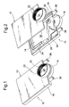
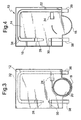
- a water supply device for a domestic washing appliance is formed ( Figures 1 - 4 ) by only two parts, namely a body 10 and a cover 12, which are advantageously produced from plastic material by injection moulding.
- the body 10 has a bottom wall 14, from the side edge of which a transverse wall 16 rises, and which has a substantially rectangular shape, the central part of one of the short sides having a semicircular protrusion 18.
- the cover 12 has a shape corresponding to that of the bottom wall 14, and is fixed, in particular by welding, to the upper edge of the transverse wall 16.
- the bottom wall 14 is pierced by a further through hole 24 which is intended to communicate with the outside and which defines the maximum level which can be reached by the water in the washing chamber of the domestic appliance.
- a cavity 26 is formed between the walls 14, 16 of the body 10 and the cover 12, and contains an air gap device formed by a first and a second half-conduit 28, 30 which taper at their respective ends which are tubular, namely with a closed cross section, face each other, and are made integrally with the bottom wall 14.
- the facing ends of the two half-conduits 28, 30 are substantially aligned, namely are arranged along the same straight line, so that one half-conduit forms a kind of linear prolongation of the other.
- the first half-conduit 28 also constitutes the extension of a supply conduit 32, formed by facing side walls 34 which protrude from the bottom wall 14 and are closed at their free edges by the cover 12.
- the supply conduit 32 has a U-shaped layout and comprises an entry portion 36 protruding outside the transverse wall 16 at one side of the semicircular protrusion 18.
- the second half-conduit 30 comprises, at its end opposite to its tapered end, a terminal portion 38 protruding outside the transverse wall 16, at the opposite side of the semicircular protrusion 18.
- the supply device is mounted on the domestic appliance in such a way as to ensure that the cover 12 and the bottom wall 14 are positioned in respective vertical planes, and that the internal cavity 26 acts as a vent for the vapour generated in the washing chamber.
- This assembly also causes the tubular facing ends of the two half-conduits 28, 30 to be arranged along the same vertically orientated straight line, and causes the flow of water from one to the other to follow a straight path without the need for additional guide elements.
- the half-conduits forming the air gap device could be made integrally with the cover, instead of with the bottom wall of the body.
- the facing side walls forming the supply conduit could protrude from the cover and be closed on their free edges by the bottom wall of the body.
Landscapes
- Engineering & Computer Science (AREA)
- Water Supply & Treatment (AREA)
- Textile Engineering (AREA)
- Detail Structures Of Washing Machines And Dryers (AREA)
- Vaporization, Distillation, Condensation, Sublimation, And Cold Traps (AREA)
- Paper (AREA)
- Massaging Devices (AREA)
Description
- The present invention relates to a water supply device, commonly called an "air break" in the technical parlance, for domestic washing appliances, such as dishwashers and washing machines.
- A device of this type typically comprises a flattened hollow body of plastic material, which is connected to other components of the domestic appliance and is shaped in such a way that it can perform various functions, by providing, for example, a vent for vapour formed in the washing chamber, an air gap for the water supply, a collector of water for use in forming regeneration brine for ion exchange resins of the water softener, and the like.
- There is a known way of producing a device of this type in three different parts which are manufactured separately by injection moulding and are then welded together to provide the various required functions. However, the assembly of this number of parts makes the production process complex and expensive.
-
DE-24 17 732 discloses an air gap device for a domestic washing appliance, which is depicted as monolithic and has nozzles whose end has an hemi-spherical shape. -
GB-2 155 316 - The object of the present invention is therefore to overcome the aforementioned drawbacks of the known art.
- According to the invention, this object is achieved by means of a water supply device having the features indicated in
Claim 1 below. Preferred features of this device are indicated in the dependent claims numbered 2 to 7. - The construction of the device according to the invention in only two parts yields a corresponding simplification of the production process: in particular, all the components of the air gap device are formed in one piece, thus automatically preventing possible malfunctions caused by incorrect mutual positioning.
- In particular, it should be noted that, according to the present invention, the respective tubular tapered mutually facing ends of the first and second half-conduit are produced integrally with the body of the distributor device (or alternatively with its cover), thus yielding a considerable advantage over the case in which these ends are formed by the assembly of a cover on to a body, as illustrated in
DE-A-29 08 824 : this is because positioning errors due to the assembly of different pieces, which could compromise the correct operation of the air gap device, are automatically avoided. - It should also be noted that the phrase indicating that the first and second half-conduits have "respective mutually facing ends" means that the aforesaid ends are substantially aligned, in other words arranged on the same straight line, so that one half-conduit forms a kind of linear prolongation of the other. This arrangement has the advantage of not requiring the presence of deflector elements or the like which would guide the flow of water from one half-conduit to the other, and therefore enables the operation of the air gap device to be optimized.
- A further object of the present invention is a domestic washing appliance comprising a supply device of the aforementioned type.
- Other advantages and characteristics of the present invention will become clear from the following detailed description which is given by way of non-limiting example with reference to the attached drawings, in which:
-
Figure 1 is a perspective view of a device according to the invention, -
Figure 2 is an exploded perspective view of the device ofFigure 1 , -
Figure 3 is a plan view of the device of the preceding figures, and -
Figure 4 is a plan view of one of the two component parts of the device of the preceding figures. - A water supply device for a domestic washing appliance is formed (
Figures 1 - 4 ) by only two parts, namely abody 10 and acover 12, which are advantageously produced from plastic material by injection moulding. - The
body 10 has abottom wall 14, from the side edge of which atransverse wall 16 rises, and which has a substantially rectangular shape, the central part of one of the short sides having asemicircular protrusion 18. - The
cover 12 has a shape corresponding to that of thebottom wall 14, and is fixed, in particular by welding, to the upper edge of thetransverse wall 16. Acircular hole 20, half of which extends into thesemicircular protrusion 18, and which is surrounded by awall 22 protruding from the face opposite to thebody 10, is also formed in thecover 12. Thebottom wall 14 is pierced by a further throughhole 24 which is intended to communicate with the outside and which defines the maximum level which can be reached by the water in the washing chamber of the domestic appliance. - A
cavity 26 is formed between thewalls body 10 and thecover 12, and contains an air gap device formed by a first and a second half-conduit bottom wall 14. - The facing ends of the two half-
conduits - The first half-
conduit 28 also constitutes the extension of asupply conduit 32, formed by facingside walls 34 which protrude from thebottom wall 14 and are closed at their free edges by thecover 12. Thesupply conduit 32 has a U-shaped layout and comprises anentry portion 36 protruding outside thetransverse wall 16 at one side of thesemicircular protrusion 18. - For its part, the second half-
conduit 30 comprises, at its end opposite to its tapered end, aterminal portion 38 protruding outside thetransverse wall 16, at the opposite side of thesemicircular protrusion 18. - In use, the supply device is mounted on the domestic appliance in such a way as to ensure that the
cover 12 and thebottom wall 14 are positioned in respective vertical planes, and that theinternal cavity 26 acts as a vent for the vapour generated in the washing chamber. This assembly also causes the tubular facing ends of the two half-conduits - Naturally, the principle of the invention remaining the same, the details of construction and the forms of embodiment may be varied widely with respect to those described, which have been given purely by way of example, without thereby departing from the scope of the invention as defined in the attached claims. In particular, the half-conduits forming the air gap device could be made integrally with the cover, instead of with the bottom wall of the body. Similarly, the facing side walls forming the supply conduit could protrude from the cover and be closed on their free edges by the bottom wall of the body.
Claims (10)
- Water supply device for a domestic washing appliance, formed by a body (10) having a bottom wall (14) from the side edge of which a transverse wall (16) rises, and by a cover (12) which has a shape corresponding to that of said bottom wall (14) and is fixed to the upper edge of said transverse wall (16), a cavity (26) being formed between the walls of the body (10) and the cover (12), either said bottom wall (14) or said cover (12) incorporating a first and a second half-conduit (28, 30) tapering at respective ends facing each other, so that they form an air gap device, said first half-conduit (28) constituting the extension of a supply conduit (32) formed by facing side walls (34) which protrude from the bottom wall (14) and are closed by said cover (12), or alternatively protrude from the cover (12) and are closed by said bottom wall (14), said device being characterised in that the tubular facing ends of the first and second half-conduits (28, 30) are arranged along the same straight line.
- Device according to claim 1, wherein said cover (12) is fixed by welding to the upper edge of said transverse wall (16).
- Device according to any of the previous claims, wherein said supply conduit (32) has a U-shaped layout and comprises an entry portion (36) protruding outside said transverse wall (16).
- Device according to any of the previous claims, wherein said second half-conduit (30) comprises, at its end opposite to its tapered end, a terminal portion (38) protruding outside said transverse wall (16).
- Device according to any of the previous claims, wherein said bottom wall (14) and said cover (12) have a substantially rectangular shape, the central part of one of the short sides having a semicircular protrusion (18).
- Device according to any of the previous claims, wherein a circular hole (20), which also extends into said semicircular protrusion (18) and is surrounded by a wall (22) protruding from the face of the cover (12) opposite to the body (10), is formed in said cover (12).
- Device according to any of the previous claims, wherein said bottom wall (14) is pierced by a further through hole (24).
- Domestic washing appliance comprising a water supply device according to any of the preceding claims.
- Domestic appliance according to Claim 8, comprising a water supply device wherein the cover (12) and the bottom wall (14) are positioned in respective vertical planes.
- Domestic appliance according to Claim 8 or 9, wherein the tubular facing ends of the first and second half-conduits (28, 30) are arranged along the same straight line which is orientated vertically.
Priority Applications (1)
| Application Number | Priority Date | Filing Date | Title |
|---|---|---|---|
| PL12190128T PL2586356T3 (en) | 2011-10-28 | 2012-10-26 | Water supply device |
Applications Claiming Priority (1)
| Application Number | Priority Date | Filing Date | Title |
|---|---|---|---|
| IT000984A ITTO20110984A1 (en) | 2011-10-28 | 2011-10-28 | WATER DISTRIBUTOR DEVICE |
Publications (2)
| Publication Number | Publication Date |
|---|---|
| EP2586356A1 EP2586356A1 (en) | 2013-05-01 |
| EP2586356B1 true EP2586356B1 (en) | 2015-05-06 |
Family
ID=45315983
Family Applications (1)
| Application Number | Title | Priority Date | Filing Date |
|---|---|---|---|
| EP20120190128 Active EP2586356B1 (en) | 2011-10-28 | 2012-10-26 | Water supply device |
Country Status (3)
| Country | Link |
|---|---|
| EP (1) | EP2586356B1 (en) |
| IT (1) | ITTO20110984A1 (en) |
| PL (1) | PL2586356T3 (en) |
Families Citing this family (3)
| Publication number | Priority date | Publication date | Assignee | Title |
|---|---|---|---|---|
| ITUB20169959A1 (en) * | 2016-01-13 | 2017-07-13 | T&P S P A | DISTRIBUTOR DEVICE OF LIQUID IN A HOUSEHOLD WASHING MACHINE, IN PARTICULAR A DISHWASHER AND ITS WASHING MACHINE |
| ITUB20169967A1 (en) * | 2016-01-13 | 2017-07-13 | T&P S P A | DISTRIBUTOR DEVICE OF LIQUID IN A HOUSEHOLD WASHING MACHINE, IN PARTICULAR A DISHWASHER AND ITS WASHING MACHINE |
| IT202100016658A1 (en) | 2021-06-24 | 2022-12-24 | Tp Reflex Group Spa | LIQUID DISPENSER DEVICE FOR A DOMESTIC WASHING MACHINE, IN PARTICULAR A DISHWASHER, AND RELATIVE WASHING MACHINE |
Citations (14)
| Publication number | Priority date | Publication date | Assignee | Title |
|---|---|---|---|---|
| GB1166040A (en) | 1965-12-22 | 1969-10-01 | Zanussi A Spa Industrie | Liquid Pollution Preventing Devices |
| DE2417732B1 (en) | 1974-04-11 | 1975-07-31 | Aweco, Apparate- Und Geraetebau, Gmbh & Co Kg, 7995 Neukirch | Device for preventing the backflow of liquid from a water consumption device into the water supply system |
| DE2908824A1 (en) | 1979-03-07 | 1980-09-18 | Miele & Cie | Backflow preventer for plumbed-in washing appliances - having centrifugal water flow around curved open surface between tangential jets |
| GB2063658A (en) | 1979-11-15 | 1981-06-10 | Zanussi A Spa Industrie | Adjustable-volume metering reservoir for automatic dishwashing machines |
| FR2485363A1 (en) | 1980-06-28 | 1981-12-31 | Aweco App & Geraetebau Kg | Controller for ion exchanger of dishwashing machine - uses float lever to prevent further water entry through controlled dia. inlet hole to ion exchanger reservoir |
| GB2111537A (en) | 1981-12-14 | 1983-07-06 | Zanussi A Spa Industrie | Automatic washing machine |
| FR2534798A1 (en) | 1982-10-22 | 1984-04-27 | Bosch Siemens Hausgeraete | DEVICE FOR DISPENSING WATER IN A DISHWASHER |
| GB2155316A (en) | 1984-03-13 | 1985-09-25 | Balay Sa | Hydraulic feeder having a steam outlet for dishwashers |
| EP0678274A1 (en) | 1994-04-19 | 1995-10-25 | CANDY S.p.A. | Multifunctional integrated assembly for dishwashers |
| EP0876789A1 (en) | 1997-04-24 | 1998-11-11 | Merloni Elettrodomestici S.p.A. | Dishwashing machine with improved liquid dosage device |
| EP1023869A2 (en) | 1999-01-29 | 2000-08-02 | T & P S.p.A. | Device for the drying of dishes and diswashing machine using said device |
| EP1121893A2 (en) | 2000-01-21 | 2001-08-08 | T & P S.p.A. | Device for supplying washing liquid in the tub of a household washing machine, in particular a dishwasher |
| WO2003087460A1 (en) | 2002-04-10 | 2003-10-23 | Fisher & Paykel Appliances Limited | Washing appliance water softener |
| US20080011339A1 (en) | 2006-07-12 | 2008-01-17 | Samsung Electronics Co., Ltd. | Dish washing machine |
-
2011
- 2011-10-28 IT IT000984A patent/ITTO20110984A1/en unknown
-
2012
- 2012-10-26 EP EP20120190128 patent/EP2586356B1/en active Active
- 2012-10-26 PL PL12190128T patent/PL2586356T3/en unknown
Patent Citations (15)
| Publication number | Priority date | Publication date | Assignee | Title |
|---|---|---|---|---|
| GB1166040A (en) | 1965-12-22 | 1969-10-01 | Zanussi A Spa Industrie | Liquid Pollution Preventing Devices |
| DE2417732B1 (en) | 1974-04-11 | 1975-07-31 | Aweco, Apparate- Und Geraetebau, Gmbh & Co Kg, 7995 Neukirch | Device for preventing the backflow of liquid from a water consumption device into the water supply system |
| GB1498724A (en) | 1974-04-11 | 1978-01-25 | Aweco App & Geraetebau Kg | Device for preventing the flow-back of liquid from a water device into the water supply system |
| DE2908824A1 (en) | 1979-03-07 | 1980-09-18 | Miele & Cie | Backflow preventer for plumbed-in washing appliances - having centrifugal water flow around curved open surface between tangential jets |
| GB2063658A (en) | 1979-11-15 | 1981-06-10 | Zanussi A Spa Industrie | Adjustable-volume metering reservoir for automatic dishwashing machines |
| FR2485363A1 (en) | 1980-06-28 | 1981-12-31 | Aweco App & Geraetebau Kg | Controller for ion exchanger of dishwashing machine - uses float lever to prevent further water entry through controlled dia. inlet hole to ion exchanger reservoir |
| GB2111537A (en) | 1981-12-14 | 1983-07-06 | Zanussi A Spa Industrie | Automatic washing machine |
| FR2534798A1 (en) | 1982-10-22 | 1984-04-27 | Bosch Siemens Hausgeraete | DEVICE FOR DISPENSING WATER IN A DISHWASHER |
| GB2155316A (en) | 1984-03-13 | 1985-09-25 | Balay Sa | Hydraulic feeder having a steam outlet for dishwashers |
| EP0678274A1 (en) | 1994-04-19 | 1995-10-25 | CANDY S.p.A. | Multifunctional integrated assembly for dishwashers |
| EP0876789A1 (en) | 1997-04-24 | 1998-11-11 | Merloni Elettrodomestici S.p.A. | Dishwashing machine with improved liquid dosage device |
| EP1023869A2 (en) | 1999-01-29 | 2000-08-02 | T & P S.p.A. | Device for the drying of dishes and diswashing machine using said device |
| EP1121893A2 (en) | 2000-01-21 | 2001-08-08 | T & P S.p.A. | Device for supplying washing liquid in the tub of a household washing machine, in particular a dishwasher |
| WO2003087460A1 (en) | 2002-04-10 | 2003-10-23 | Fisher & Paykel Appliances Limited | Washing appliance water softener |
| US20080011339A1 (en) | 2006-07-12 | 2008-01-17 | Samsung Electronics Co., Ltd. | Dish washing machine |
Also Published As
| Publication number | Publication date |
|---|---|
| PL2586356T3 (en) | 2015-11-30 |
| ITTO20110984A1 (en) | 2013-04-29 |
| EP2586356A1 (en) | 2013-05-01 |
Similar Documents
| Publication | Publication Date | Title |
|---|---|---|
| US11331635B2 (en) | Minute bubble generator, home appliance provided with minute bubble generator, and method of manufacturing minute bubble generator | |
| CN107137039B (en) | Dish washing machine | |
| EP2586356A1 (en) | Water supply device | |
| EP0768059A2 (en) | Device for limitation of steam released from a washing machine | |
| CN202604762U (en) | Overflow protection structure of dish washer | |
| EP2586354A1 (en) | Water supply device for a dishwasher | |
| WO2015009916A1 (en) | Combined washing and rinsing device and dishwashing machine provided therewith | |
| EP2865801B1 (en) | Laundry washing machine comprising a detergent dispensing assembly | |
| EP3310237B1 (en) | Integrated component for a dishwashing machine | |
| CN101877991B (en) | Household Appliances Running With Water | |
| KR101326461B1 (en) | Plug-in type coolant module | |
| EP3310234B1 (en) | Integrated component for a dishwashing machine | |
| CN105463788A (en) | Distributor box assembly of washing machine and washing machine with the same | |
| KR102167271B1 (en) | Faucet body using double injection and faucet with the faucet body | |
| EP2555663B1 (en) | Dishwashing machine | |
| EP3192425B1 (en) | Water supply device for a household washing machine, in particular a dishwasher, and houshold washing machine having such a device | |
| CN105167730A (en) | Spraying arm assembly for dish-washing machine and dish-washing machine | |
| KR20120111543A (en) | Dispenser cover of dispenser assembly for washing appliance | |
| KR101143560B1 (en) | Injection mold having upper-core formed cooling-line | |
| IT201800007257A1 (en) | Water dispensing device for a washing appliance. | |
| EP1836944B1 (en) | Dishwasher base | |
| JP2020159163A (en) | Water faucet device | |
| CN204363927U (en) | The inside door of dish-washing machine, door body assembly and dish-washing machine | |
| EP2586357A1 (en) | Drying device for a dishwasher | |
| EP4108151B1 (en) | Liquid dispenser device for a washing machine and washing machine thereof |
Legal Events
| Date | Code | Title | Description |
|---|---|---|---|
| PUAI | Public reference made under article 153(3) epc to a published international application that has entered the european phase |
Free format text: ORIGINAL CODE: 0009012 |
|
| AK | Designated contracting states |
Kind code of ref document: A1 Designated state(s): AL AT BE BG CH CY CZ DE DK EE ES FI FR GB GR HR HU IE IS IT LI LT LU LV MC MK MT NL NO PL PT RO RS SE SI SK SM TR |
|
| AX | Request for extension of the european patent |
Extension state: BA ME |
|
| 17P | Request for examination filed |
Effective date: 20131028 |
|
| RBV | Designated contracting states (corrected) |
Designated state(s): AL AT BE BG CH CY CZ DE DK EE ES FI FR GB GR HR HU IE IS IT LI LT LU LV MC MK MT NL NO PL PT RO RS SE SI SK SM TR |
|
| GRAP | Despatch of communication of intention to grant a patent |
Free format text: ORIGINAL CODE: EPIDOSNIGR1 |
|
| RIC1 | Information provided on ipc code assigned before grant |
Ipc: A47L 15/42 20060101AFI20141105BHEP |
|
| INTG | Intention to grant announced |
Effective date: 20141121 |
|
| GRAS | Grant fee paid |
Free format text: ORIGINAL CODE: EPIDOSNIGR3 |
|
| GRAA | (expected) grant |
Free format text: ORIGINAL CODE: 0009210 |
|
| AK | Designated contracting states |
Kind code of ref document: B1 Designated state(s): AL AT BE BG CH CY CZ DE DK EE ES FI FR GB GR HR HU IE IS IT LI LT LU LV MC MK MT NL NO PL PT RO RS SE SI SK SM TR |
|
| REG | Reference to a national code |
Ref country code: GB Ref legal event code: FG4D |
|
| REG | Reference to a national code |
Ref country code: CH Ref legal event code: EP |
|
| REG | Reference to a national code |
Ref country code: IE Ref legal event code: FG4D |
|
| REG | Reference to a national code |
Ref country code: AT Ref legal event code: REF Ref document number: 725122 Country of ref document: AT Kind code of ref document: T Effective date: 20150615 |
|
| REG | Reference to a national code |
Ref country code: DE Ref legal event code: R096 Ref document number: 602012007116 Country of ref document: DE Effective date: 20150618 |
|
| REG | Reference to a national code |
Ref country code: AT Ref legal event code: MK05 Ref document number: 725122 Country of ref document: AT Kind code of ref document: T Effective date: 20150506 |
|
| REG | Reference to a national code |
Ref country code: NL Ref legal event code: MP Effective date: 20150506 |
|
| REG | Reference to a national code |
Ref country code: LT Ref legal event code: MG4D |
|
| PG25 | Lapsed in a contracting state [announced via postgrant information from national office to epo] |
Ref country code: PT Free format text: LAPSE BECAUSE OF FAILURE TO SUBMIT A TRANSLATION OF THE DESCRIPTION OR TO PAY THE FEE WITHIN THE PRESCRIBED TIME-LIMIT Effective date: 20150907 Ref country code: LT Free format text: LAPSE BECAUSE OF FAILURE TO SUBMIT A TRANSLATION OF THE DESCRIPTION OR TO PAY THE FEE WITHIN THE PRESCRIBED TIME-LIMIT Effective date: 20150506 Ref country code: HR Free format text: LAPSE BECAUSE OF FAILURE TO SUBMIT A TRANSLATION OF THE DESCRIPTION OR TO PAY THE FEE WITHIN THE PRESCRIBED TIME-LIMIT Effective date: 20150506 Ref country code: ES Free format text: LAPSE BECAUSE OF FAILURE TO SUBMIT A TRANSLATION OF THE DESCRIPTION OR TO PAY THE FEE WITHIN THE PRESCRIBED TIME-LIMIT Effective date: 20150506 Ref country code: FI Free format text: LAPSE BECAUSE OF FAILURE TO SUBMIT A TRANSLATION OF THE DESCRIPTION OR TO PAY THE FEE WITHIN THE PRESCRIBED TIME-LIMIT Effective date: 20150506 Ref country code: NO Free format text: LAPSE BECAUSE OF FAILURE TO SUBMIT A TRANSLATION OF THE DESCRIPTION OR TO PAY THE FEE WITHIN THE PRESCRIBED TIME-LIMIT Effective date: 20150806 |
|
| PG25 | Lapsed in a contracting state [announced via postgrant information from national office to epo] |
Ref country code: AT Free format text: LAPSE BECAUSE OF FAILURE TO SUBMIT A TRANSLATION OF THE DESCRIPTION OR TO PAY THE FEE WITHIN THE PRESCRIBED TIME-LIMIT Effective date: 20150506 Ref country code: IS Free format text: LAPSE BECAUSE OF FAILURE TO SUBMIT A TRANSLATION OF THE DESCRIPTION OR TO PAY THE FEE WITHIN THE PRESCRIBED TIME-LIMIT Effective date: 20150906 Ref country code: RS Free format text: LAPSE BECAUSE OF FAILURE TO SUBMIT A TRANSLATION OF THE DESCRIPTION OR TO PAY THE FEE WITHIN THE PRESCRIBED TIME-LIMIT Effective date: 20150506 Ref country code: LV Free format text: LAPSE BECAUSE OF FAILURE TO SUBMIT A TRANSLATION OF THE DESCRIPTION OR TO PAY THE FEE WITHIN THE PRESCRIBED TIME-LIMIT Effective date: 20150506 Ref country code: GR Free format text: LAPSE BECAUSE OF FAILURE TO SUBMIT A TRANSLATION OF THE DESCRIPTION OR TO PAY THE FEE WITHIN THE PRESCRIBED TIME-LIMIT Effective date: 20150807 Ref country code: BG Free format text: LAPSE BECAUSE OF FAILURE TO SUBMIT A TRANSLATION OF THE DESCRIPTION OR TO PAY THE FEE WITHIN THE PRESCRIBED TIME-LIMIT Effective date: 20150806 |
|
| REG | Reference to a national code |
Ref country code: PL Ref legal event code: T3 |
|
| PG25 | Lapsed in a contracting state [announced via postgrant information from national office to epo] |
Ref country code: DK Free format text: LAPSE BECAUSE OF FAILURE TO SUBMIT A TRANSLATION OF THE DESCRIPTION OR TO PAY THE FEE WITHIN THE PRESCRIBED TIME-LIMIT Effective date: 20150506 Ref country code: EE Free format text: LAPSE BECAUSE OF FAILURE TO SUBMIT A TRANSLATION OF THE DESCRIPTION OR TO PAY THE FEE WITHIN THE PRESCRIBED TIME-LIMIT Effective date: 20150506 |
|
| REG | Reference to a national code |
Ref country code: DE Ref legal event code: R026 Ref document number: 602012007116 Country of ref document: DE |
|
| PLBI | Opposition filed |
Free format text: ORIGINAL CODE: 0009260 |
|
| PG25 | Lapsed in a contracting state [announced via postgrant information from national office to epo] |
Ref country code: SK Free format text: LAPSE BECAUSE OF FAILURE TO SUBMIT A TRANSLATION OF THE DESCRIPTION OR TO PAY THE FEE WITHIN THE PRESCRIBED TIME-LIMIT Effective date: 20150506 Ref country code: CZ Free format text: LAPSE BECAUSE OF FAILURE TO SUBMIT A TRANSLATION OF THE DESCRIPTION OR TO PAY THE FEE WITHIN THE PRESCRIBED TIME-LIMIT Effective date: 20150506 Ref country code: RO Free format text: LAPSE BECAUSE OF NON-PAYMENT OF DUE FEES Effective date: 20150506 |
|
| PLAX | Notice of opposition and request to file observation + time limit sent |
Free format text: ORIGINAL CODE: EPIDOSNOBS2 |
|
| 26 | Opposition filed |
Opponent name: T & P - S.P.A. Effective date: 20160204 |
|
| PG25 | Lapsed in a contracting state [announced via postgrant information from national office to epo] |
Ref country code: IT Free format text: LAPSE BECAUSE OF FAILURE TO SUBMIT A TRANSLATION OF THE DESCRIPTION OR TO PAY THE FEE WITHIN THE PRESCRIBED TIME-LIMIT Effective date: 20150506 |
|
| PG25 | Lapsed in a contracting state [announced via postgrant information from national office to epo] |
Ref country code: SI Free format text: LAPSE BECAUSE OF FAILURE TO SUBMIT A TRANSLATION OF THE DESCRIPTION OR TO PAY THE FEE WITHIN THE PRESCRIBED TIME-LIMIT Effective date: 20150506 Ref country code: LU Free format text: LAPSE BECAUSE OF FAILURE TO SUBMIT A TRANSLATION OF THE DESCRIPTION OR TO PAY THE FEE WITHIN THE PRESCRIBED TIME-LIMIT Effective date: 20151026 |
|
| REG | Reference to a national code |
Ref country code: CH Ref legal event code: PL |
|
| PG25 | Lapsed in a contracting state [announced via postgrant information from national office to epo] |
Ref country code: MC Free format text: LAPSE BECAUSE OF FAILURE TO SUBMIT A TRANSLATION OF THE DESCRIPTION OR TO PAY THE FEE WITHIN THE PRESCRIBED TIME-LIMIT Effective date: 20150506 |
|
| PLBB | Reply of patent proprietor to notice(s) of opposition received |
Free format text: ORIGINAL CODE: EPIDOSNOBS3 |
|
| REG | Reference to a national code |
Ref country code: IE Ref legal event code: MM4A |
|
| PG25 | Lapsed in a contracting state [announced via postgrant information from national office to epo] |
Ref country code: CH Free format text: LAPSE BECAUSE OF NON-PAYMENT OF DUE FEES Effective date: 20151031 Ref country code: LI Free format text: LAPSE BECAUSE OF NON-PAYMENT OF DUE FEES Effective date: 20151031 |
|
| REG | Reference to a national code |
Ref country code: FR Ref legal event code: ST Effective date: 20160630 |
|
| PG25 | Lapsed in a contracting state [announced via postgrant information from national office to epo] |
Ref country code: FR Free format text: LAPSE BECAUSE OF NON-PAYMENT OF DUE FEES Effective date: 20151102 Ref country code: BE Free format text: LAPSE BECAUSE OF FAILURE TO SUBMIT A TRANSLATION OF THE DESCRIPTION OR TO PAY THE FEE WITHIN THE PRESCRIBED TIME-LIMIT Effective date: 20150506 |
|
| PG25 | Lapsed in a contracting state [announced via postgrant information from national office to epo] |
Ref country code: IE Free format text: LAPSE BECAUSE OF NON-PAYMENT OF DUE FEES Effective date: 20151026 |
|
| PG25 | Lapsed in a contracting state [announced via postgrant information from national office to epo] |
Ref country code: SM Free format text: LAPSE BECAUSE OF FAILURE TO SUBMIT A TRANSLATION OF THE DESCRIPTION OR TO PAY THE FEE WITHIN THE PRESCRIBED TIME-LIMIT Effective date: 20150506 Ref country code: HU Free format text: LAPSE BECAUSE OF FAILURE TO SUBMIT A TRANSLATION OF THE DESCRIPTION OR TO PAY THE FEE WITHIN THE PRESCRIBED TIME-LIMIT; INVALID AB INITIO Effective date: 20121026 |
|
| PLAB | Opposition data, opponent's data or that of the opponent's representative modified |
Free format text: ORIGINAL CODE: 0009299OPPO |
|
| GBPC | Gb: european patent ceased through non-payment of renewal fee |
Effective date: 20161026 |
|
| PG25 | Lapsed in a contracting state [announced via postgrant information from national office to epo] |
Ref country code: CY Free format text: LAPSE BECAUSE OF FAILURE TO SUBMIT A TRANSLATION OF THE DESCRIPTION OR TO PAY THE FEE WITHIN THE PRESCRIBED TIME-LIMIT Effective date: 20150506 Ref country code: NL Free format text: LAPSE BECAUSE OF FAILURE TO SUBMIT A TRANSLATION OF THE DESCRIPTION OR TO PAY THE FEE WITHIN THE PRESCRIBED TIME-LIMIT Effective date: 20150506 Ref country code: SE Free format text: LAPSE BECAUSE OF FAILURE TO SUBMIT A TRANSLATION OF THE DESCRIPTION OR TO PAY THE FEE WITHIN THE PRESCRIBED TIME-LIMIT Effective date: 20150506 |
|
| R26 | Opposition filed (corrected) |
Opponent name: TP REFLEX GROUP S.P.A. Effective date: 20160204 |
|
| RAP2 | Party data changed (patent owner data changed or rights of a patent transferred) |
Owner name: BITRON S.P.A. |
|
| PG25 | Lapsed in a contracting state [announced via postgrant information from national office to epo] |
Ref country code: GB Free format text: LAPSE BECAUSE OF NON-PAYMENT OF DUE FEES Effective date: 20161026 |
|
| PLCK | Communication despatched that opposition was rejected |
Free format text: ORIGINAL CODE: EPIDOSNREJ1 |
|
| STAA | Information on the status of an ep patent application or granted ep patent |
Free format text: STATUS: THE PATENT HAS BEEN GRANTED |
|
| PG25 | Lapsed in a contracting state [announced via postgrant information from national office to epo] |
Ref country code: MT Free format text: LAPSE BECAUSE OF FAILURE TO SUBMIT A TRANSLATION OF THE DESCRIPTION OR TO PAY THE FEE WITHIN THE PRESCRIBED TIME-LIMIT Effective date: 20150506 |
|
| APBM | Appeal reference recorded |
Free format text: ORIGINAL CODE: EPIDOSNREFNO |
|
| APBP | Date of receipt of notice of appeal recorded |
Free format text: ORIGINAL CODE: EPIDOSNNOA2O |
|
| APAH | Appeal reference modified |
Free format text: ORIGINAL CODE: EPIDOSCREFNO |
|
| APBQ | Date of receipt of statement of grounds of appeal recorded |
Free format text: ORIGINAL CODE: EPIDOSNNOA3O |
|
| PG25 | Lapsed in a contracting state [announced via postgrant information from national office to epo] |
Ref country code: MK Free format text: LAPSE BECAUSE OF FAILURE TO SUBMIT A TRANSLATION OF THE DESCRIPTION OR TO PAY THE FEE WITHIN THE PRESCRIBED TIME-LIMIT Effective date: 20150506 Ref country code: TR Free format text: LAPSE BECAUSE OF FAILURE TO SUBMIT A TRANSLATION OF THE DESCRIPTION OR TO PAY THE FEE WITHIN THE PRESCRIBED TIME-LIMIT Effective date: 20150506 |
|
| PG25 | Lapsed in a contracting state [announced via postgrant information from national office to epo] |
Ref country code: AL Free format text: LAPSE BECAUSE OF FAILURE TO SUBMIT A TRANSLATION OF THE DESCRIPTION OR TO PAY THE FEE WITHIN THE PRESCRIBED TIME-LIMIT Effective date: 20150506 |
|
| PLAB | Opposition data, opponent's data or that of the opponent's representative modified |
Free format text: ORIGINAL CODE: 0009299OPPO |
|
| R26 | Opposition filed (corrected) |
Opponent name: TP REFLEX GROUP S.P.A. Effective date: 20160204 |
|
| REG | Reference to a national code |
Ref country code: DE Ref legal event code: R100 Ref document number: 602012007116 Country of ref document: DE |
|
| APBU | Appeal procedure closed |
Free format text: ORIGINAL CODE: EPIDOSNNOA9O |
|
| PLBN | Opposition rejected |
Free format text: ORIGINAL CODE: 0009273 |
|
| STAA | Information on the status of an ep patent application or granted ep patent |
Free format text: STATUS: OPPOSITION REJECTED |
|
| 27O | Opposition rejected |
Effective date: 20210311 |
|
| PGFP | Annual fee paid to national office [announced via postgrant information from national office to epo] |
Ref country code: PL Payment date: 20240827 Year of fee payment: 13 |
|
| PGFP | Annual fee paid to national office [announced via postgrant information from national office to epo] |
Ref country code: DE Payment date: 20241015 Year of fee payment: 13 |
|
| REG | Reference to a national code |
Ref country code: DE Ref legal event code: R119 Ref document number: 602012007116 Country of ref document: DE |
|
| PG25 | Lapsed in a contracting state [announced via postgrant information from national office to epo] |
Ref country code: DE Free format text: LAPSE BECAUSE OF NON-PAYMENT OF DUE FEES Effective date: 20260501 |