EP2585689B1 - Carter d'huile destine a etre fixe a un bloc moteur - Google Patents
Carter d'huile destine a etre fixe a un bloc moteur Download PDFInfo
- Publication number
- EP2585689B1 EP2585689B1 EP11717306.2A EP11717306A EP2585689B1 EP 2585689 B1 EP2585689 B1 EP 2585689B1 EP 11717306 A EP11717306 A EP 11717306A EP 2585689 B1 EP2585689 B1 EP 2585689B1
- Authority
- EP
- European Patent Office
- Prior art keywords
- oil
- strainer
- shell
- wall
- oil sump
- Prior art date
- Legal status (The legal status is an assumption and is not a legal conclusion. Google has not performed a legal analysis and makes no representation as to the accuracy of the status listed.)
- Active
Links
Images


Classifications
-
- F—MECHANICAL ENGINEERING; LIGHTING; HEATING; WEAPONS; BLASTING
- F01—MACHINES OR ENGINES IN GENERAL; ENGINE PLANTS IN GENERAL; STEAM ENGINES
- F01M—LUBRICATING OF MACHINES OR ENGINES IN GENERAL; LUBRICATING INTERNAL COMBUSTION ENGINES; CRANKCASE VENTILATING
- F01M11/00—Component parts, details or accessories, not provided for in, or of interest apart from, groups F01M1/00 - F01M9/00
- F01M11/0004—Oilsumps
- F01M2011/0008—Oilsumps with means for reducing vibrations
- F01M2011/0012—Oilsumps with means for reducing vibrations with acoustic insulation
-
- F—MECHANICAL ENGINEERING; LIGHTING; HEATING; WEAPONS; BLASTING
- F01—MACHINES OR ENGINES IN GENERAL; ENGINE PLANTS IN GENERAL; STEAM ENGINES
- F01M—LUBRICATING OF MACHINES OR ENGINES IN GENERAL; LUBRICATING INTERNAL COMBUSTION ENGINES; CRANKCASE VENTILATING
- F01M11/00—Component parts, details or accessories, not provided for in, or of interest apart from, groups F01M1/00 - F01M9/00
- F01M11/0004—Oilsumps
- F01M2011/002—Oilsumps with means for improving the stiffness
-
- F—MECHANICAL ENGINEERING; LIGHTING; HEATING; WEAPONS; BLASTING
- F01—MACHINES OR ENGINES IN GENERAL; ENGINE PLANTS IN GENERAL; STEAM ENGINES
- F01M—LUBRICATING OF MACHINES OR ENGINES IN GENERAL; LUBRICATING INTERNAL COMBUSTION ENGINES; CRANKCASE VENTILATING
- F01M11/00—Component parts, details or accessories, not provided for in, or of interest apart from, groups F01M1/00 - F01M9/00
- F01M11/0004—Oilsumps
- F01M2011/0029—Oilsumps with oil filters
-
- F—MECHANICAL ENGINEERING; LIGHTING; HEATING; WEAPONS; BLASTING
- F01—MACHINES OR ENGINES IN GENERAL; ENGINE PLANTS IN GENERAL; STEAM ENGINES
- F01M—LUBRICATING OF MACHINES OR ENGINES IN GENERAL; LUBRICATING INTERNAL COMBUSTION ENGINES; CRANKCASE VENTILATING
- F01M11/00—Component parts, details or accessories, not provided for in, or of interest apart from, groups F01M1/00 - F01M9/00
- F01M11/0004—Oilsumps
- F01M2011/0033—Oilsumps with special means for guiding the return of oil into the sump
-
- F—MECHANICAL ENGINEERING; LIGHTING; HEATING; WEAPONS; BLASTING
- F01—MACHINES OR ENGINES IN GENERAL; ENGINE PLANTS IN GENERAL; STEAM ENGINES
- F01M—LUBRICATING OF MACHINES OR ENGINES IN GENERAL; LUBRICATING INTERNAL COMBUSTION ENGINES; CRANKCASE VENTILATING
- F01M11/00—Component parts, details or accessories, not provided for in, or of interest apart from, groups F01M1/00 - F01M9/00
- F01M11/0004—Oilsumps
- F01M2011/005—Oilsumps with special anti-turbulence means, e.g. anti-foaming means or intermediate plates
-
- F—MECHANICAL ENGINEERING; LIGHTING; HEATING; WEAPONS; BLASTING
- F01—MACHINES OR ENGINES IN GENERAL; ENGINE PLANTS IN GENERAL; STEAM ENGINES
- F01M—LUBRICATING OF MACHINES OR ENGINES IN GENERAL; LUBRICATING INTERNAL COMBUSTION ENGINES; CRANKCASE VENTILATING
- F01M11/00—Component parts, details or accessories, not provided for in, or of interest apart from, groups F01M1/00 - F01M9/00
- F01M11/0004—Oilsumps
- F01M2011/0066—Oilsumps with passages in the wall, e.g. for axles or fluid passages
-
- F—MECHANICAL ENGINEERING; LIGHTING; HEATING; WEAPONS; BLASTING
- F01—MACHINES OR ENGINES IN GENERAL; ENGINE PLANTS IN GENERAL; STEAM ENGINES
- F01M—LUBRICATING OF MACHINES OR ENGINES IN GENERAL; LUBRICATING INTERNAL COMBUSTION ENGINES; CRANKCASE VENTILATING
- F01M11/00—Component parts, details or accessories, not provided for in, or of interest apart from, groups F01M1/00 - F01M9/00
- F01M11/0004—Oilsumps
- F01M2011/007—Oil pickup tube to oil pump, e.g. strainer
-
- F—MECHANICAL ENGINEERING; LIGHTING; HEATING; WEAPONS; BLASTING
- F01—MACHINES OR ENGINES IN GENERAL; ENGINE PLANTS IN GENERAL; STEAM ENGINES
- F01M—LUBRICATING OF MACHINES OR ENGINES IN GENERAL; LUBRICATING INTERNAL COMBUSTION ENGINES; CRANKCASE VENTILATING
- F01M11/00—Component parts, details or accessories, not provided for in, or of interest apart from, groups F01M1/00 - F01M9/00
- F01M11/0004—Oilsumps
- F01M2011/0087—Sump being made of different parts
-
- F—MECHANICAL ENGINEERING; LIGHTING; HEATING; WEAPONS; BLASTING
- F01—MACHINES OR ENGINES IN GENERAL; ENGINE PLANTS IN GENERAL; STEAM ENGINES
- F01M—LUBRICATING OF MACHINES OR ENGINES IN GENERAL; LUBRICATING INTERNAL COMBUSTION ENGINES; CRANKCASE VENTILATING
- F01M11/00—Component parts, details or accessories, not provided for in, or of interest apart from, groups F01M1/00 - F01M9/00
- F01M11/0004—Oilsumps
- F01M2011/0091—Oilsumps characterised by used materials
Definitions
- the present invention relates to an oil pan intended to be fixed under the engine block of an internal combustion engine.
- the main purpose of an oil sump is to collect the oils used to lubricate all mechanical parts in rotational or translational motion (eg camshafts, valve stems, crankshaft bearings, piston / cylinder interfaces, piston / connecting rods, crankshaft / connecting rods, etc.).
- the oil pump propels the oil towards these different parts to be lubricated, and the oil then drops back to the crankcase by at least one circuit (by natural trickle or ducted return depending on the case).
- an oil pan has a lower shell which is fixed under the engine block.
- This type of casing receives in its internal volume a strainer, to stop the solids contained in the oil so that they reach the suction port of the pump, and an anti-emulsion plate, whose role is to prevent or limit the movements of the oil in the crankcase, in particular to the free surface of the oil.
- Oil sump type devices incorporating different components of the oil circulation system described by the documents are already known.
- EP1276974 B1 and EP 2 133 596 the oil sump is constituted by a lower shell molded in a reinforced thermoplastic material and having internal and external reinforcement ribs, as well as at least one longitudinal separator and a transverse separator making it possible to stiffen the casing.
- An insert serving as an anti-emulsion plate is attached and bears, in assembled position, on the separators.
- the housing contains an oil pump arranged parallel to an oil lifting line.
- a disadvantage of this housing is its high production cost, particularly due to the addition of longitudinal and transverse separators.
- the integration of an oil pump on the bottom of the housing causes additional space in the housing. This last disadvantage greatly limits the increase of the ground clearance and / or limits the increase of the hood guard if the motor is translated downwards.
- EP0358895 A2 which, like many other documents, describes an oil sump incorporating an oil strainer arranged freely at a predefined distance from the bottom of the sump and allowing the oil to be sucked.
- the major disadvantage of this type of casing is in the event of a severe impact on the crankcase at the level of the strainer, the latter may be clogged and cause the stoppage of the oil circulation, thus causing the engine to fail.
- the present invention aims to overcome the disadvantages mentioned above.
- the invention relates to an oil pan intended to be fixed to an engine block, comprising a lower shell, a strainer and an anti-emulsion plate, wherein the lower shell comprises an element forming a lower portion of the strainer. , the lower shell and said element being made in one piece by molding, the housing further comprising an upper shell comprising an element forming an upper portion of the strainer, and a wall forming the anti-emulsion plate, the upper shell, said element and the anti-emulsion plate being made in one piece by molding.
- the lower and upper shells are tightly assembled to one another to form a rigid casing, the lower portion and the upper portion of the strainer being, in the assembled state of the shells, assembled one to the other. other sealingly, with interposition of a grid, so as to form a strainer allowing the aspiration of oil to the engine.
- the invention provides an oil sump consisting essentially of two separate parts assembled to one another and comprising, in an integrated manner and not reported, the strainer and the anti-emulsion plate.
- the production in one piece of the lower shell and the lower portion of the strainer, and on the other hand the upper shell, the upper portion of the strainer and the anti-emulsion plate, ensures stiffening of the casing of oil and allows the formation of a solid structure of the low engine module.
- the invention therefore makes it possible to reduce the cost of manufacturing such casings, as compared with the prior art.
- One of the advantages of the present invention is to use the oil strainer as stiffening element along the three axes X, Y and Z (the Z axis being the vertical axis, and the X, Y axes defining a horizontal plane).
- This rigidifying element integrated and not reported, makes it possible to compensate for the creep of the material - especially when it is a thermoplastic - (Z axis) in direct and permanent contact with a certain mass of oil subjected to high temperatures (about 110 ° C continuously, up to 160 ° C maximum), vibrations and accelerations.
- This stiffening occurs both in a generally horizontal plane (X, Y) close to the fastening flange to the engine block and in a generally vertical plane solidarisant said plane with the bottom of the housing.
- thermoplastic generally polyamide 6 or polyamide 6-6 or stiffening elements reported type screwed bridges for example or as described in the document EP1276974 B1 , the addition of longitudinal and / or transverse separators.
- the lower shell comprises a bottom wall and a peripheral wall, the lower portion of the strainer protruding from said bottom wall upwards, and the upper shell comprises an upper wall and a peripheral wall, the upper portion of the strainer projecting from said upper wall downwards.
- the lower and upper shells are assembled at their periphery and the lower and upper portions of the strainer are also assembled at their periphery.
- the lower and upper shells have peripheral edges of complementary shapes and that, moreover, the lower and upper portions of the strainer also have peripheral edges of complementary shapes. Thanks to the invention, the lower and upper portions of the strainer participate in optimal centering between the two shells.
- the lower portion of the strainer comprises a hollow foot protruding from a bottom wall of the lower shell, said foot having at least one notch formed near said bottom wall, so as to allow the suction of the oil from the interior volume of the lower shell in said foot.
- the present invention can significantly reduce the risk of air intake between the oil pump and the strainer.
- the lower portion of the strainer comprises for example an open channel at its upper part, supported by two feet projecting from a bottom wall of the lower shell, at least one foot being hollow and arranged to allow the suction of the oil from the interior volume of the lower shell to said channel.
- the upper portion of the strainer may comprise a channel formed in an upper wall of the upper shell, said channel being open downwards and opening out of the housing by an orifice formed in said upper wall and surrounded by a substantially cylindrical portion forming the strainer outlet.
- the integrated strainer outlet to the upper shell ensures the centering of said housing relative to the engine block.
- the upper shell comprises an upper wall and a peripheral wall, the upper wall constituting the anti-emulsion plate.
- the latter is therefore integrated into the upper shell.
- the lower shell is provided on its outer surface with ribs - for example oriented ribs - intended to stiffen the housing and to absorb energy by breaking said ribs during impacts.
- the upper shell has an upper wall having, at its periphery, a plurality of perforations for fixing said housing to the engine block with the interposition of a seal.
- the upper wall may have, at its periphery, a groove receiving a seal capable of sealing between said housing and the engine block.
- the casing may further comprise a soundproofing and / or shock absorbing part assembled under said casing, for example by fixing means cooperating with at least one of the outer faces of the lower shell of said casing.
- the oil sump module or low engine according to the invention has the advantage of allowing the realization of forms in strong undercut in the lower part of the housing, and thus to gain a certain volume laterally but also to reduce the vertical footprint.
- the direct consequence of this advantage is an increase in the ground clearance and / or an increase in guard hood if the engine is translated down (to overcome the problem of pedestrian impact).
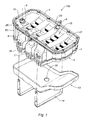
- the figure 1 illustrates a low engine module or oil sump module 100 composed of an upper shell 1 and a lower shell 2 assembled to one another.
- the oil sump 100 is intended to be fixed under the engine block 24 of an internal combustion engine, as illustrated in FIG. figure 6 .
- the Z axis is defined as the vertical axis, and the X, Y axes as defining a horizontal plane.
- the terms “superior”, “lower”, “high” and “low” are used in reference to the Z axis.
- the term “longitudinal” is used with reference to the Y axis, while the term “transverse” is used with reference to the X axis.
- the housing 100 is described in the position it occupies in the figures.
- the upper shell 1 incorporates various components necessary for the proper functioning of the device.
- the upper shell 1 is made in one piece by molding. It may for example be obtained by injection of a plastic material, by molding a thermosetting, or by molding aluminum. It comprises an upper wall 15 which forms an anti-emulsion plate 15 provided with orifices 27 permitting a first passage of the oil coming from the engine block 24 towards the interior volume of the casing 100.
- the upper shell 1 also comprises a peripheral wall 50 protruding from the periphery of the upper wall 15 and formed, in the embodiment shown, of four side walls. A second passage 23 of oil formed in the anti-emulsion plate 15, and which can follow one of said side walls, is directly connected with the bottom of the housing 100.
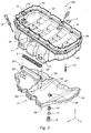
- the upper shell 1 further comprises an electric probe 6 and its fastening clip 7 for the purpose of informing the dashboard of a vehicle concerning the level, the temperature or the quality of the oil, an oil dipstick 8 and its housing 28 (illustrated in figure 2 ) for a control of the manual oil level, a plurality of perforations 26 on the upper edge of said upper shell 1 for fixing the oil sump 100 to the engine block 24, for example by screw spacers 12 (illustrated in FIG. figure 2 ).
- a seal 4 located on the upper edge of the upper shell 1 is intended to ensure a seal between the oil sump 100 and the engine block 24.
- fastening systems 17 disposed on either side of said upper shell 1 to allow the attachment of a piece 13 soundproofing and / or protection.
- the upper shell 1 has an element projecting from the upper wall 15 downwards (that is to say towards the inside of the casing 100 in the assembled position) and which forms an upper portion 21 of a strainer.
- the upper portion 21 of the strainer comprises a channel formed in the upper wall 15 of the upper shell 1, said channel being open downwards and opening outwardly of the housing 100 through an orifice formed in said upper wall 1 and surrounded by a substantially cylindrical portion forming the outlet
- the strainer outlet 19, with its gasket 5 makes it possible to raise the oil from the bottom of the casing 100 towards the various parts of the engine requiring lubrication, and also allows the centering of the casing 100 with respect to the engine block. 24 when mounting said housing 100.
- the integration of the upper portion of the strainer 21 to the upper shell 1 of the oil sump 100 is particularly shown in FIG. figures 3 and 6 .
- the anti-emulsion plate 15, the upper portion of the strainer 21 and the upper shell 1 form a single piece.
- the lower shell 2 is made in one piece by molding. It may for example be obtained by injection of a plastic material, by molding a thermosetting, or by molding aluminum. It comprises a bottom wall 51 and a peripheral wall 52 projecting from the periphery of the bottom wall 51 and formed, in the embodiment shown, of four side walls.
- the lower shell 2 has an element projecting from the bottom wall 51 upwards (that is to say towards the inside of the casing 100 in the assembled position) and which forms a lower portion 20 of a strainer.
- the lower portion 20 of the strainer comprises a channel 55 substantially horizontal and open at its upper part, supported by two feet 53, 54 protruding from the bottom wall 51.
- the foot 54 is hollow and has a notch 18 formed near the the bottom wall 51, so as to allow the suction of the oil from the interior of the lower shell 2 in said foot 54 to the channel 55.
- the notch 18 allows to calibrate and therefore control the flow of suction of oil into the strainer formed by the assembly of the lower portion 20 and the upper portion 21 of strainer. Furthermore, the notch 18 prevents any plugging of the strainer and thus to ensure a constant oil suction space.
- the lower portion of the strainer 20 and the lower shell 2 form a single piece.
- the lower shell 2 has on the outer face of its bottom wall 51 a series of ribs 16 oriented transversely and / or longitudinally, providing resistance to grit and impact.
- the bottom wall 54 further includes an orifice 29 for the evacuation of used oils.
- a plug closing orifice 29 is assembled on the lower shell 2, either directly or via a metal insert. Fixing the cap to the lower shell or the insert can be done either via a thread or via another solution for example a quarter-turn helical ramp.
- the seal is provided by a flat seal (axial seal) or preferably an O-ring (radial seal).
- This plug comprises a drain plug 9 and a seal 11. It may for example be composed of three parts, namely a drain plug 9, optionally an insert 10 - which can be threaded or not, which can be integral with the lower shell or a separate part - for fixing the plug and a seal 11 of drain plug.
- the lower shell 2 also has a wall 60 projecting from the bottom wall 54 inwards, and the function of which is to ensure an always sufficient oil level at the notch 18 for avoid drawing air into the strainer.
- This wall 60 - said anti-lift wall - is particularly useful during strong accelerations longitudinal (acceleration or braking) or transverse (right or left turns) during which the oil undergoes significant displacement.
- the lower and upper shells 1 and 2 are joined to each other along the free edge of their peripheral walls 52, 50, sealingly, thereby forming a housing. Simultaneously, the lower and upper portions 21 of strainer are assembled at their periphery, a screen 3 of mesh being trapped between said lower and upper portions 21.
- the assembly of the shells 1, 2, on the one hand, and portions 20, 21 of strainer, on the other hand, can be obtained by welding.
- the required rigidity of the oil sump 100 is obtained on the one hand by the fact that the strainer and the anti-emulsion plate are not inserts but integrated into the shells 1, 2.
- the strainer by the assembly of a lower portion 20 of integrated strainer to the lower shell 2 and an upper portion 21 of strainer integrated in the upper shell 1, the rigidity is further improved.
- a piece 13 soundproofing and / or protection is fixed under the lower shell 2 by fastening lugs 14 coming to mate with the attachment systems 17 formed on the upper shell 1.
- This part 13 which can be multilayer - for example a rubber layer and an absorbent layer (foam and / or fibrous) - produces a soundproofing effect and protection of the lower shell 2.
- said part 13 comprises an orifice 30 for the evacuation of used oils, for example during a drain, and arranged opposite the orifice 29of the lower shell 2.
- the figure 3 which is a longitudinal sectional view of the casing 100 showing the inside of the casing and the strainer, makes it possible to identify the points of contact between the lower and upper casing hulls 2 and 1 and those of the lower and upper portions 20 and 21 of the casing. the strainer. These contact points are the assembly areas of the housing 100. Said assembly zones are located along the periphery of the lower shell 2 and upper shell 1 as well as the periphery of the lower portions 20 and upper 21 of the strainer. Ideally and by way of example, the assembly is done by welding, the most suitable welding being the contactless infrared welding. This type of welding makes it possible to achieve a high level of cleanliness, this being a requirement for an oil circuit of an internal combustion engine.
- the infrared weld also makes it possible to effectively weld the internal profile at the level of the stiffeners (the borders of the periphery), which the vibration welding does not allow, for example, because of the almost total inaccessibility of this profile during the welding.
- the figures 4 and 5 illustrate the different paths that can take the oil from the engine block 24 and then move, by gravity or routing, in the bottom of the lower shell 2 of the housing 100.
- the figure 4 shows the passage or path S1 of the oil through the orifices 27 of the anti-emulsion plate 15 allowing a tasting flow to taste oil towards the bottom of the lower shell 2 of the casing 100.
- figure 5 illustrates a second path S2 or rather a pipe 23 for routing oil from the engine block 24 directly to the bottom of the lower shell 2 of the housing 100.
- the pipe 23 runs along the wall of the upper shell 1 to the bottom of the lower shell 2 of the housing 100.
- Path S1 is usually referred to as a main oil return circuit characterized by the natural runoff of the oil projected by the nozzles under the pistons.
- Path S2 is considered as a secondary circuit characterized by a channelized return of the oil from the cylinder head.
- the path S1 is taken by the oils coming from the low engine, for example the oils coming from the crankshaft / connecting rod interface as well as from the crankshaft bearing.
- the path S2 serves as a return circuit of the oils coming from the high engine and the engine center including the oils lubricating the camshaft, the valve stems but also the oils coming from the interface piston / cylinder and pistons / rods.
- the figure 6 shows schematically the integration of the anti-emulsion plate 15 and the upper portion 21 of the strainer to the upper shell 1, thus forming a single piece, and the integration of the lower portion 20 of the strainer to the lower shell 2, also forming a single piece.
- One of the essential points of the present invention is that the aforementioned elements are not reported but integrated.
- the figure 6 also shows the order of assembly of the main parts constituting the casing 100 according to the present invention.
- the lower shell 2 - incorporating the lower portion 20 of the strainer - is assembled to the upper shell 1 - integrating the upper portion 21 of the strainer and the anti-emulsion plate 15 -, trapping the screen grid 3.
- the casing thus formed is then attached to the engine block 24 by inserting an oil pan gasket 4.
- FIGS. 7 and 8 illustrate a casing 100 according to a second embodiment of the invention.
- the oil sump 100 includes a housing for an oil filter 31, an oil cooler 32, and the associated oil circulation circuit.
- the oil filter and its housing 31 and the oil radiator 32 may be arranged either on the lower shell 2 or on the upper shell 1 of the housing 100.
- the oil collected in the casing 100, and more particularly in the lower shell 2 can then, before being conveyed to the engine, be treated, that is to say filtered and then cooled by following the following route: the oil is sucked through an oil pump (not shown) allowing it to escape from the oil sump through the strainer outlet 19 to be routed to an orifice 36 directly connected to the housing of the oil filter 31. Once filtered, the purified oil takes the line 41 leading to the oil radiator 32. The refined and hot oil then enters the radiator 32 through its inlet 40 for exit through the conduit 39 provided for this purpose. The filtered and cooled oil can finally be conveyed to the engine block 24 through the duct outlet 37.
- the supply of oil radiator 32 is provided by a water circuit comprising an inlet 34 and an outlet 33 for cooling the oil by heat exchange.
- the housing 100 has a reinforcement 35 provided on at least one of the outer sides of the casing 100, which ensures, in part, the fixing of the gearbox and a part of the force recovery on the motor block 24.
- This reinforcement 35 may be attached, in the case of a metal reinforcement, or integrated to the upper shell 1 in the case of a reinforcement obtained by plastic injection.
- the housing 100 includes a housing for oil filter 31 but no oil cooler.
- the oil is sucked through an oil pump allowing it to escape from the oil sump through the strainer outlet 19 to be routed to an orifice 36 directly connected to the housing of the oil filter 31.
- the purified oil takes the line 37 to be directly routed to the moving parts to lubricate the engine.
- the housing 100 illustrated on the figure 9 also comprises a reinforcement 35, similar to the housing illustrated on the Figures 7 and 8 .
- the reinforcement 35 is obtained by plastic injection and integrated into the upper shell 1 of the housing 100. It comprises a plurality of ribs 42 providing additional strength between the oil sump 100 and the gearbox.
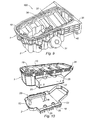
- the top 1 and bottom 2 shells have corresponding lateral excrescences, which creates, in the assembled state, an additional lateral volume 22 in the casing 100.
- This additional lateral volume 22 accommodates a oil filter and / or an oil cooler and / or other components necessary for the proper operation of the oil circuit in the housing 100.
- At least one chimney 25 is integrated therein, in order to allow access to the fasteners of the lateral volume 22 by screws, but also to provide an additional reinforcing and structuring element of the casing 100 as a whole.
Description
- La présente invention concerne un carter d'huile destiné à être fixé sous le bloc moteur d'un moteur à combustion interne.
- Le principal objectif d'un carter d'huile est de récolter les huiles utilisées pour lubrifier l'ensemble des pièces mécaniques en mouvement de rotation ou de translation (par exemple les arbres à cames, les tiges de soupapes, les paliers de vilebrequin, les interfaces piston/cylindre, piston/bielles, vilebrequin/bielles, etc.). La pompe à huile propulse l'huile vers ces différentes pièces à lubrifier, et l'huile retombe ensuite vers le carter par au moins un circuit (par ruissellement naturel ou par retour canalisé selon les cas).
- De façon classique, un carter d'huile comporte une coque inférieure qui est fixée sous le bloc moteur. Ce type de carter reçoit dans son volume intérieur une crépine, permettant d'arrêter les matières solides contenues dans l'huile pour ne pas qu'elles atteignent l'orifice d'aspiration de la pompe, et une plaque anti émulsion, dont le rôle est d'empêcher ou de limiter les mouvements de l'huile dans le carter, en particulier à la surface libre de l'huile.
- On connaît déjà des dispositifs de type carter d'huile intégrant différents composant du système de circulation d'huile décrit par les documents
EP1276974 B1 etEP 2 133 596 . Selon ce document, le carter d'huile est constitué d'une coque inférieure moulée en une matière thermoplastique renforcée et possédant des nervures internes et externes de renforcement, ainsi qu'au moins un séparateur longitudinal et un séparateur transversal permettant de rigidifier le carter. Un insert, servant de plaque anti émulsion, est rapporté et prend appui, en position assemblée, sur les séparateurs. De plus, le carter contient une pompe à huile disposée parallèlement à une ligne de levage d'huile. Un inconvénient de ce carter est son coût de production élevé, notamment dû à l'ajout des séparateurs longitudinaux et transversaux. Par ailleurs, l'intégration d'une pompe à huile sur le fond du carter entraîne un encombrement supplémentaire du carter. Ce dernier inconvénient limite fortement l'accroissement de la garde au sol et/ou limite l'accroissement de la garde au capot si le moteur est translaté vers le bas. - On connaît également le document
EP0358895 A2 qui, comme de nombreux autres documents, décrit un carter d'huile intégrant une crépine d'huile disposée librement à une distance prédéfinie du fond du carter et permettant l'aspiration de l'huile. L'inconvénient majeur de ce type de carter est qu'en cas de choc important sur le carter au niveau de la crépine, cette dernière peut s'obturer et entraîner l'arrêt de la circulation d'huile, provoquant ainsi la panne du moteur. - La présente invention vise à remédier aux inconvénients mentionnés ci-dessus.
- A cet effet, l'invention concerne un carter d'huile destiné à être fixé à un bloc moteur, comprenant une coque inférieure, une crépine et une plaque anti émulsion, dans lequel la coque inférieure comporte un élément formant une portion inférieure de la crépine, la coque inférieure et ledit élément étant réalisés d'une seule pièce par moulage, le carter comprenant en outre une coque supérieure comportant un élément formant une portion supérieure de la crépine, et une paroi formant la plaque anti émulsion, la coque supérieure, ledit élément et la plaque anti émulsion étant réalisés d'une seule pièce par moulage. Les coques inférieure et supérieure sont assemblées l'une à l'autre de façon étanche pour former un boîtier rigide, la portion inférieure et la portion supérieure de la crépine étant, à l'état assemblé des coques, assemblées l'une à l'autre de façon étanche, avec interposition d'une grille, de façon à former une crépine permettant l'aspiration d'huile vers le moteur.
- Ainsi, l'invention fournit un carter d'huile constitué pour l'essentiel de deux pièces distinctes assemblées l'une à l'autre et comportant, de façon intégrée et non rapportée, la crépine et la plaque anti émulsion. La réalisation en une seule pièce d'une part de la coque inférieure et de la portion inférieure de crépine, et d'autre part de la coque supérieure, de la portion supérieure de crépine et de la plaque anti émulsion, assure une rigidification du carter d'huile et permet la formation d'une structure solide du module bas moteur.
- Pour obtenir un carter de rigidité requise, il n'est donc pas nécessaire de prévoir d'éléments de renforcement internes. L'invention permet donc de réduire le coût de fabrication de tels carters, par rapport à l'art antérieur.
- L'un des avantages de la présente invention est d'utiliser la crépine d'huile comme élément de rigidification selon les trois axes X, Y et Z (l'axe Z étant l'axe vertical, et les axes X, Y définissant un plan horizontal). Cet élément rigidifiant, intégré et non rapporté, permet de palier le fluage de la matière - notamment lorsqu'il s'agit d'un thermoplastique - (axe Z) au contact direct et permanent d'une certaine masse d'huile soumise à de fortes températures (environ 110°C en continu, pouvant atteindre 160°C au maximum), vibrations et accélérations. Cette rigidification intervient à la fois dans un plan globalement horizontal (X, Y) proche de la bride de fixation au bloc moteur et dans un plan globalement vertical solidarisant ledit plan avec le fond du carter. Il permet, dans le cas de l'utilisation de matière plastique, de s'affranchir de l'utilisation de fibres de verre longues dans la matrice du thermoplastique, généralement du polyamide 6 ou polyamide 6-6 ou d'éléments rigidifiants rapportés de type pontets vissés par exemple ou comme, décrit dans le document
EP1276974 B1 , de l'ajout de séparateurs longitudinaux et/ou transversaux. - Avantageusement, la coque inférieure comprend une paroi de fond et une paroi périphérique, la portion inférieure de la crépine faisant saillie de ladite paroi de fond vers le haut, et la coque supérieure comprend une paroi supérieure et une paroi périphérique, la portion supérieure de la crépine faisant saillie de ladite paroi supérieure vers le bas. Les coques inférieure et supérieure sont assemblées à leur périphérie et les portions inférieure et supérieure de la crépine sont également assemblées à leur périphérie.
- On comprend donc que les coques inférieure et supérieure présentent des bords périphériques de formes complémentaires et que, par ailleurs, les portions inférieure et supérieure de la crépine présentent également des bords périphériques de formes complémentaires. Grâce à l'invention, les portions inférieure et supérieure de la crépine participent au centrage optimal entre les deux coques.
- Selon une réalisation possible, la portion inférieure de la crépine comporte un pied creux faisant saillie d'une paroi de fond de la coque inférieure, ledit pied présentant au moins une encoche ménagée à proximité de ladite paroi de fond, de façon à permettre l'aspiration de l'huile depuis le volume intérieur de la coque inférieure dans ledit pied.
- Ceci permet de calibrer l'aspiration de l'huile dans la crépine et de garantir un espace d'aspiration d'huile constant et sans risque d'obturation. En effet, puisque la portion inférieure de la crépine est venue de moulage avec la coque inférieure, la hauteur de l'encoche reste constante même en cas de choc sous la coque inférieure, car ceci aurait pour effet de déplacer vers le haut à la fois la paroi de fond de la coque inférieure et le pied de la portion inférieure de la crépine. Le module de carter d'huile ou bas moteur, tel que décrit, permet d'obtenir un avantage indéniable et jamais atteint, celui de pouvoir simplifier la chaîne de côtes et maîtriser les intervalles de tolérance entre la face interne du carter ou le fond du carter et le plan d'entrée de la crépine. Par ailleurs, la présente invention permet de réduire considérablement le risque de prise d'air entre la pompe à huile et la crépine.
- La portion inférieure de la crépine comporte par exemple un canal ouvert à sa partie supérieure, supporté par deux pieds faisant saillie d'une paroi de fond de la coque inférieure, au moins un pied étant creux et agencé pour permettre l'aspiration de l'huile depuis le volume intérieur de la coque inférieure vers ledit canal.
- Par ailleurs, la portion supérieure de la crépine peut comprendre un canal ménagé dans une paroi supérieure de la coque supérieure, ledit canal étant ouvert vers le bas et débouchant à l'extérieur du carter par un orifice ménagé dans ladite paroi supérieure et entouré d'une portion sensiblement cylindrique formant la sortie de crépine. La sortie de crépine intégrée à la coque supérieure permet d'assurer le centrage dudit carter par rapport au bloc moteur.
- Avantageusement, la coque supérieure comprend une paroi supérieure et une paroi périphérique, la paroi supérieure constituant la plaque anti émulsion. Cette dernière est donc intégrée à la coque supérieure.
- On peut prévoir que la coque inférieure soit pourvue, sur sa surface extérieure, de nervures - par exemple de nervures orientées - destinées à rigidifier le carter et à absorber l'énergie par rupture desdites nervures lors d'impacts.
- Typiquement, la coque supérieure présente une paroi supérieure présentant, à sa périphérie, une pluralité de perforations permettant la fixation dudit carter au bloc moteur avec interposition d'un joint d'étanchéité. Par exemple, la paroi supérieure peut présenter, à sa périphérie, une gorge recevant un joint apte à assurer l'étanchéité entre ledit carter et le bloc moteur.
- Le carter peut en outre comprendre une pièce d'insonorisation et/ou d'absorption de chocs assemblée sous ledit carter, par exemple par des moyens de fixation coopérant avec au moins l'une des faces extérieures de la coque inférieure dudit carter.
- Par ailleurs, on peut prévoir :
- un logement pour recevoir une jauge à huile et/ou une sonde électrique de niveau d'huile, aménagé sur la coque supérieure ou inférieure ;
- un logement pour un filtre à huile, ménagé sur la coque supérieure ou inférieure, pour recevoir un filtre à huile ;
- et/ou des moyens de fixation, ménagés sur la coque supérieure ou inférieure, pour recevoir un radiateur d'huile.
- Le module de carter d'huile ou bas moteur selon l'invention a l'avantage de permettre la réalisation de formes en forte contre-dépouille dans la partie basse du carter, et donc de gagner un certain volume latéralement mais aussi de réduire l'encombrement vertical. La conséquence directe de cet avantage est un accroissement de la garde au sol et/ou un accroissement de la garde au capot si le moteur est translaté vers le bas (pour palier la problématique du choc piéton).
- D'autre part, lorsque le carter d'huile selon l'invention est réalisé en matière plastique, cela permet un fort niveau d'intégration de fonctions et donc engendre à la fois un intérêt économique par rapport à un carter aluminium ainsi qu'une amélioration des prestations techniques :
- gain économique à iso-fonction ;
- gain de poids ;
- gain en garde au sol et/ou garde au capot ;
- gain en volume d'huile permettant d'augmenter la périodicité de maintenance ;
- gain en surface d'huile en contact de l'air permettant un dégazage plus rapide ;
- gain acoustique ;
- réduction de l'usure moteur due aux démarrages à froid. En effet, le carter plastique est plus isolant thermiquement et permet des montées en température d'huile plus rapides ;
- gain en temps d'assemblage et en logistique en usine moteur ;
- nouvelles possibilités d'intégration de fonctions (filtration d'huile, radiateur d'huile, ... et toute pièce plastique avoisinante).
- D'autres caractéristiques et avantages de l'invention apparaîtront au cours de la description détaillée qui va suivre pour la compréhension de laquelle on se reportera aux dessins annexés parmi lesquels :
- la
figure 1 est une vue schématique en perspective d'un carter d'huile selon un premier mode de réalisation de l'invention, les coques supérieure et inférieure dudit carter étant assemblées entre elles, et le carter possédant en outre une pièce d'insonorisation et/ou d'absorption de chocs, - la
figure 2 est une vue en perspective du carter de lafigure 1 , les coques supérieure et inférieure dudit carter étant désolidarisées, - la
figure 3 est une vue en coupe longitudinale du carter de lafigure 1 , les deux coques étant assemblées, montrant la partie intérieure du carter d'huile et la crépine, - la
figure 4 est une vue en coupe transversale du carter d'huile de lafigure 1 , selon le plan A de lafigure 3 , montrant un premier passage d'huile se dirigeant vers le fond du carter par les orifices de la plaque anti-émulsion, - la
figure 5 est une vue en coupe transversale du carter d'huile de lafigure 1 , selon le plan B de lafigure 3 , montrant un deuxième passage d'huile se dirigeant vers le fond du carter par les orifices de la plaque anti-émulsion, - la
figure 6 est une vue schématique explosée et en coupe longitudinale du carter d'huile de lafigure 1 et d'un bloc moteur sous lequel il est destiné à être fixé, - la
figure 7 est une vue en perspective d'un carter d'huile selon un deuxième mode de réalisation de l'invention, les coques supérieure et inférieure dudit carter étant assemblées, le carter possédant en outre un renfort permettant la fixation, en partie, d'une boîte de vitesse, cette figure montrant l'emplacement d'un filtre à huile et d'un radiateur d'huile, - la
figure 8 est une vue en plan de dessus de la coque supérieure du carter de lafigure 7 , montrant de façon schématique les canalisations permettant de conduire l'huile de la pompe à huile vers le moteur en passant par le filtre à huile et le radiateur d'huile, - la
figure 9 est une vue en perspective d'un carter d'huile selon un troisième mode de réalisation de l'invention montrant l'emplacement d'un filtre à huile et d'un renfort permettant la fixation, en partie, d'une boîte de vitesse, - la
figure 10 est une vue en perspective d'un carter d'huile selon un quatrième mode de réalisation de l'invention, les coques supérieure et inférieure dudit carter n'étant pas assemblées, le carter définissant un volume latéral supplémentaire. - De manière non limitative, la
figure 1 illustre un module bas moteur ou module carter d'huile 100 composé d'une coque supérieure 1 et d'une coque inférieure 2 assemblées l'une à l'autre. Le carter d'huile 100 est destiné à être fixé sous le bloc moteur 24 d'un moteur à combustion interne, comme illustré sur lafigure 6 . - Comme représenté sur la
figure 2 , on définit l'axe Z comme étant l'axe vertical, et les axes X, Y comme définissant un plan horizontal. Les termes « supérieur », « inférieur », « haut » et « bas » sont employés en référence à l'axe Z. Le terme « longitudinal » est employé en référence à l'axe Y, tandis que le terme « transversal » est employé en référence à l'axe X. Le carter 100 est décrit dans la position qu'il occupe sur les figures. - La coque supérieure 1 intègre différents composants nécessaires au bon fonctionnement du dispositif.
- La coque supérieure 1 est réalisée d'une seule pièce par moulage. Elle peut par exemple être obtenue par injection d'une matière plastique, par moulage d'un thermodurcissable, ou par moulage d'aluminium. Elle comprend une paroi supérieure 15 qui forme une plaque anti-émulsion 15 pourvue d'orifices 27 permettant un premier passage de l'huile provenant du bloc moteur 24 vers le volume intérieur du carter 100. La coque supérieure 1 comprend également une paroi périphérique 50 faisant saillie de la périphérie de la paroi supérieure 15 et formée, dans la réalisation représentée, de quatre parois latérales. Un deuxième passage 23 d'huile ménagé dans la plaque anti émulsion 15, et pouvant longer l'une desdites parois latérales, est directement connecté avec le fond du carter 100.
- La coque supérieure 1 comprend en outre une sonde électrique 6 et son agrafe de fixation 7 dans l'objectif de renseigner le tableau de bord d'un véhicule concernant le niveau, la température ou la qualité de l'huile, une jauge à huile 8 et son logement 28 (illustré en
figure 2 ) pour un contrôle du niveau d'huile manuel, une pluralité de perforations 26 sur la bordure supérieure de ladite coque supérieure 1 permettant la fixation du carter d'huile 100 au bloc moteur 24, par exemple par des entretoises avec vis 12 (illustrées enfigure 2 ). Un joint 4 situé sur la bordure supérieure de la coque supérieure 1 vise à assurer une étanchéité entre le carter d'huile 100 et le bloc moteur 24. - Sur la paroi périphérique 50 de la coque supérieure 1 sont prévus des systèmes d'accrochage 17 disposés de part et d'autre de ladite coque supérieure 1 pour permettre la fixation d'une pièce 13 insonorisante et/ou de protection.
- La coque supérieure 1 comporte un élément faisant saillie de la paroi supérieure 15 vers le bas (c'est-à-dire vers l'intérieur du carter 100 en position assemblée) et qui forme une portion supérieure 21 d'une crépine. La portion supérieure 21 de la crépine comprend un canal ménagé dans la paroi supérieure 15 de la coque supérieure 1, ledit canal étant ouvert vers le bas et débouchant à l'extérieur du carter 100 par un orifice ménagé dans ladite paroi supérieure 1 et entouré d'une portion sensiblement cylindrique formant la sortie de crépine 19. La sortie de crépine 19, avec son joint 5, permet de faire remonter l'huile du fond du carter 100 vers les différentes pièces du moteur nécessitant une lubrification, et permet également le centrage du carter 100 par rapport au bloc moteur 24 lors du montage dudit carter 100.
- L'intégration de la portion supérieure de la crépine 21 à la coque supérieure 1 du carter d'huile 100 est notamment montrée en
figures 3 et6 . Selon une caractéristique essentielle de l'invention, la plaque anti-émulsion 15, la portion supérieure de la crépine 21 et la coque supérieure 1 ne forment qu'une seule pièce. - La coque inférieure 2, telle que représentée sur la
figure 1 , est réalisée d'une seule pièce par moulage. Elle peut par exemple être obtenue par injection d'une matière plastique, par moulage d'un thermodurcissable, ou par moulage d'aluminium. Elle comprend une paroi de fond 51 et une paroi périphérique 52 faisant saillie de la périphérie de la paroi de fond 51 et formée, dans la réalisation représentée, de quatre parois latérales. - La coque inférieure 2 comporte un élément faisant saillie de la paroi de fond 51 vers le haut (c'est-à-dire vers l'intérieur du carter 100 en position assemblée) et qui forme une portion inférieure 20 d'une crépine. La portion inférieure 20 de la crépine comprend un canal 55 sensiblement horizontal et ouvert à sa partie supérieure, supporté par deux pieds 53, 54 faisant saillie de la paroi de fond 51. Le pied 54 est creux et présente une encoche 18 ménagée à proximité de la paroi de fond 51, de façon à permettre l'aspiration de l'huile depuis le volume intérieur de la coque inférieure 2 dans ledit pied 54 vers le canal 55. L'encoche 18 permet de calibrer et donc de contrôler le débit d'aspiration d'huile dans la crépine formée par l'assemblage de la portion inférieure 20 et de la portion supérieure 21 de crépine. Par ailleurs, l'encoche 18 permet d'éviter toute obturation de la crépine et ainsi de garantir un espace d'aspiration d'huile constant.
- Selon une caractéristique essentielle de l'invention, la portion inférieure de la crépine 20 et la coque inférieure 2 ne forment qu'une seule pièce.
- En outre, la coque inférieure 2 présente sur la face extérieure de sa paroi de fond 51 une série de nervures 16 orientées transversalement et/ou longitudinalement, assurant une résistance aux gravillonnages et aux impacts.
- La paroi de fond 54 comprend par ailleurs un orifice 29 permettant l'évacuation des huiles usagées. Un bouchon obturant l'orifice 29 est assemblé sur la coque inférieure 2, soit directement soit par l'intermédiaire d'un insert métallique. La fixation du bouchon à la coque inférieure ou à l'insert peut se faire soit via un filetage soit via une autre solution par exemple une rampe hélicoïdale de type quart de tour. L'étanchéité est assurée par un joint plat (étanchéité axiale) ou préférentiellement un joint torique (étanchéité radiale). Ce bouchon comprend un bouchon de vidange 9 et un joint 11. Il peut par exemple être composé de trois pièces, à savoir un bouchon de vidange 9, de façon optionnelle un insert 10 - qui peut être fileté ou non, qui peut être solidaire de la coque inférieure ou une pièce distincte - pour la fixation du bouchon et un joint 11 de bouchon de vidange.
- Selon une réalisation avantageuse, la coque inférieure 2 comporte également une paroi 60 faisant saillie de la paroi de fond 54 vers l'intérieur, et dont la fonction est d'assurer un niveau d'huile toujours suffisant au niveau de l'encoche 18 pour éviter l'aspiration d'air dans la crépine. Cette paroi 60 - dite paroi anti déjaugeage - est notamment utile lors des fortes accélérations longitudinales (accélération ou freinage) ou transversales (virages droite ou gauche) au cours desquelles l'huile subit un important déplacement.
- Les coques inférieure 2 et supérieure 1 sont assemblées l'une à l'autre le long du bord libre de leurs parois périphériques 52, 50, de façon étanche, formant ainsi un boîtier. Simultanément, les portions inférieure 20 et supérieure 21 de crépine sont assemblées à leur périphérie, une grille 3 de crépine étant emprisonnée entre lesdites portions inférieure 20 et supérieure 21. L'assemblage des coques 1, 2, d'une part, et des portions 20, 21 de crépine, d'autre part, peut être obtenu par soudage.
- La rigidité requise du carter d'huile 100 est obtenue d'une part par le fait que la crépine et la plaque anti émulsion ne sont pas des pièces rapportées mais intégrées aux coques 1, 2. D'autre part, en réalisant la crépine par l'assemblage d'une portion inférieure 20 de crépine intégrée à la coque inférieure 2 et une portion supérieure 21 de crépine intégrée à la coque supérieure 1, la rigidité est encore améliorée.
- Ensuite, une pièce 13 insonorisante et/ou de protection est fixée sous la coque inférieure 2 par des pattes de fixation 14 venant s'accoupler avec les systèmes d'accrochage 17 ménagés sur la coque supérieure 1. Cette pièce 13, pouvant être multicouche - par exemple une couche caoutchouteuse et une couche absorbante (mousse et/ou fibreuse) - produit un effet d'insonorisation et de protection de la coque inférieure 2. De plus, pour une raison pratique, ladite pièce 13 comporte un orifice 30 permettant l'évacuation des huiles usagées, par exemple lors d'une vidange, et disposé en regard de l'orifice 29de la coque inférieure 2.
- La
figure 3 , qui est une vue en coupe longitudinale du carter 100 montrant l'intérieur du carter et la crépine, permet d'identifier les points de contact entre les coques inférieure 2 et supérieure 1 du carter ainsi que ceux des portions inférieure 20 et supérieure 21 de la crépine. Ces points de contact sont les zones d'assemblage du carter 100. Lesdites zones d'assemblage se situent tout au long de la périphérie des coques inférieure 2 et supérieure 1 du carter ainsi que de la périphérie des portions inférieure 20 et supérieure 21 de la crépine. Idéalement et à titre d'exemple, l'assemblage s'effectue par soudage, la soudure la plus appropriée étant la soudure infrarouge sans contact. Ce type de soudure permet notamment d'atteindre un niveau de propreté élevé, ceci étant une exigence pour un circuit d'huile d'un moteur à combustion interne. La soudure infrarouge permet en outre de souder efficacement le profil interne au niveau des raidisseurs (les bordures de la périphérie), ce que ne permet pas la soudure vibration, par exemple, du fait de l'inaccessibilité quasi totale de ce profil lors de la soudure. - Les
figures 4 et5 illustrent les différents chemins que peut emprunter l'huile provenant du bloc moteur 24 pour ensuite se diriger, par gravité ou acheminement, dans le fond de la coque inférieure 2 du carter 100. - La
figure 4 montre le passage ou chemin S1 de l'huile à travers les orifices 27 de la plaque anti-émulsion 15 permettant un écoulement goûte à goûte de l'huile vers le fond de la coque inférieure 2 du carter 100. - De la même manière, la
figure 5 illustre un deuxième chemin S2 ou plutôt une canalisation 23 permettant d'acheminer l'huile provenant du bloc moteur 24 directement vers le fond de la coque inférieure 2 du carter 100. Selon un mode de réalisation préférée, comme illustré enfigure 5 , la canalisation 23 longe la paroi de la coque supérieure 1 jusqu'au fond de la coque inférieure 2 du carter 100. - Selon l'architecture du moteur, l'huile pourra emprunter l'un et/ou l'autre des deux chemins S1, S2 en fonction de besoins prédéfinis d'évacuation de l'huile vers la coque inférieure 2 du carter. Le chemin S1 est habituellement qualifié de circuit principal de retour d'huile caractérisé par le ruissellement naturel de l'huile projetée par les gicleurs sous les pistons. Le chemin S2 est considéré comme un circuit secondaire caractérisé par un retour canalisé de l'huile provenant de la culasse. Selon un mode de réalisation préféré, le chemin S1 est emprunté par les huiles provenant du bas moteur, par exemple les huiles provenant de l'interface vilebrequin/bielles ainsi que du palier de vilebrequin. Pour des raisons pratiques, le chemin S2 sert de circuit de retour des huiles provenant du haut moteur et du centre moteur notamment les huiles lubrifiant l'arbre à cames, les tiges de soupapes mais aussi les huiles provenant de l'interface piston/cylindre et pistons/bielles.
- La
figure 6 montre de manière schématique l'intégration de la plaque anti-émulsion 15 et de la portion supérieure 21 de la crépine à la coque supérieure 1, formant ainsi une seule pièce, ainsi que l'intégration de la portion inférieure 20 de la crépine à la coque inférieure 2, formant également une seule pièce. L'un des points essentiels de la présente invention est que les éléments précités ne sont pas rapportés mais intégrés. - La
figure 6 montre également l'ordre de montage des principales pièces constituant le carter 100 selon la présente invention. La coque inférieure 2 - intégrant la portion inférieure 20 de la crépine - est assemblée à la coque supérieure 1 - intégrant la portion supérieure 21 de la crépine et la plaque anti-émulsion 15 -, en emprisonnant la grille de crépine 3. Le boîtier ainsi formé est alors fixé au bloc moteur 24 en intercalant un joint de carter d'huile 4. - On se réfère à présent aux
figures 7 et 8 qui illustrent un carter 100 selon un deuxième mode de réalisation de l'invention. - Dans ce mode de réalisation, le carter d'huile 100 intègre un logement pour un filtre à huile 31, un radiateur d'huile 32, ainsi que le circuit de circulation d'huile associé. Le filtre à huile et son logement 31 ainsi que le radiateur d'huile 32 peuvent être aménagés soit sur la coque inférieure 2 soit sur la coque supérieure 1 du carter 100.
- L'huile recueillie dans le carter 100, et plus particulièrement dans la coque inférieure 2, peut alors, avant d'être acheminée vers le moteur, être traitée c'est à dire filtrée puis refroidie en suivant le parcours suivant : l'huile est aspirée via une pompe à huile (non représentée) lui permettant de s'échapper du carter d'huile par la sortie de crépine 19 pour être acheminée vers un orifice 36 directement relié au logement du filtre à huile 31. Une fois filtrée, l'huile épurée emprunte la canalisation 41 conduisant au radiateur d'huile 32. L'huile épurée et chaude entre alors dans le radiateur 32 par son entrée 40 pour en ressortir par le conduit 39 prévu à cet effet. L'huile filtrée et refroidie peut finalement être acheminée vers le bloc moteur 24 par la sortie de conduit 37.
- L'alimentation du radiateur d'huile 32 est assurée par un circuit d'eau comprenant une entrée 34 et une sortie 33 permettant le refroidissement de l'huile par échange de chaleur.
- Par ailleurs, le carter 100 possède un renfort 35 prévu sur au moins l'un des côtés extérieurs du carter 100, qui assure, en partie, la fixation de la boîte de vitesse ainsi qu'une partie de la reprise d'effort sur le bloc moteur 24. Ce renfort 35 peut être rapporté, dans le cas d'un renfort métallique, ou intégré à la coque supérieure 1 dans le cas d'un renfort obtenu par injection de matière plastique.
- Selon un troisième mode de réalisation, illustré sur la
figure 9 , le carter 100 comprend un logement pour filtre à huile 31 mais pas de radiateur d'huile. Dans ce cas, l'huile est aspirée via une pompe à huile lui permettant de s'échapper du carter d'huile par la sortie de crépine 19 pour être acheminée vers un orifice 36 directement relié au logement du filtre à huile 31. Une fois filtrée, l'huile épurée emprunte la canalisation 37 pour être directement acheminée vers les parties mobiles à lubrifier du moteur. - Le carter 100 illustré sur la
figure 9 comporte également un renfort 35, de façon similaire au carter illustré sur lesfigures 7 et 8 . Dans ce mode de réalisation, le renfort 35 est obtenu par injection de matière plastique et intégré à la coque supérieure 1 du carter 100. Il comprend plusieurs nervures 42 assurant une solidité supplémentaire entre le carter d'huile 100 et la boîte de vitesse. - Enfin, on se réfère à la
figure 10 qui illustre un quatrième mode de réalisation de l'invention. - Dans ce mode de réalisation, les coques supérieure 1 et inférieure 2 possèdent des excroissances latérales se correspondant, ce qui crée, à l'état assemblé, un volume latéral 22 supplémentaire dans le carter 100. Ce volume latéral 22 supplémentaire permet d'accueillir un filtre à huile et/ou un radiateur d'huile et/ou autres composants nécessaires au bon fonctionnement du circuit d'huile dans le carter 100.
- Lorsque ce volume latéral supplémentaire est prévu, au moins une cheminée 25 y est intégrée, afin de permettre un accès aux fixations du volume latéral 22 par des vis mais aussi de fournir un élément de renfort et de structuration supplémentaire du carter 100 dans son ensemble.
Claims (12)
- Carter d'huile destiné à être fixé à un bloc moteur (24), comprenant une coque inférieure, une crépine et une plaque anti émulsion,
dans lequel:- la coque inférieure (2) comporte un élément formant une portion inférieure (20) de la crépine, la coque inférieure (2) et ledit élément (20) étant réalisés d'une seule pièce par moulage ;- le carter (100) comprend en outre une coque supérieure (1) comportant un élément formant une portion supérieure de la crépine (21), et une paroi formant la plaque anti émulsion (15), la coque supérieure (1), ledit élément (21) et la plaque anti émulsion (15) étant réalisés d'une seule pièce par moulage ;
les coques inférieure et supérieure (2, 1) étant assemblées l'une à l'autre de façon étanche pour former un boîtier rigide, la portion inférieure et la portion supérieure (20, 21) de la crépine étant, à l'état assemblé des coques, assemblées l'une à l'autre de façon étanche, avec interposition d'une grille (3), de façon à former une crépine permettant l'aspiration d'huile vers le moteur. - Carter d'huile selon la revendication 1, caractérisé en ce que la coque inférieure (2) comprend une paroi de fond (51) et une paroi périphérique (52), la portion inférieure (20) de la crépine faisant saillie de ladite paroi de fond (51) vers le haut, et en ce que la coque supérieure (1) comprend une paroi supérieure (15) et une paroi périphérique (50), la portion supérieure (21) de la crépine faisant saillie de ladite paroi supérieure (15) vers le bas, les coques inférieure et supérieure (2, 1) étant assemblées à leur périphérie et les portions inférieure et supérieure (20, 21) de la crépine étant également assemblées à leur périphérie.
- Carter d'huile selon la revendication 1 ou 2, caractérisé en ce que la portion inférieure (20) de la crépine comporte un pied creux (54) faisant saillie d'une paroi de fond (51) de la coque inférieure (2), ledit pied (54) présentant au moins une encoche (18) ménagée à proximité de ladite paroi de fond (51), de façon à permettre l'aspiration de l'huile depuis le volume intérieur de la coque inférieure (2) dans ledit pied (54).
- Carter d'huile selon l'une des revendications 1 à 3, caractérisé en ce que la portion inférieure (20) de la crépine comporte un canal (55) ouvert à sa partie supérieure, supporté par deux pieds (53, 54) faisant saillie d'une paroi de fond (51) de la coque inférieure (2), au moins un pied (54) étant creux et agencé pour permettre l'aspiration de l'huile depuis le volume intérieur de la coque inférieure (2) vers ledit canal (55).
- Carter d'huile selon l'une des revendications 1 à 4, caractérisé en ce que la portion supérieure (21) de la crépine comprend un canal ménagé dans une paroi supérieure (15) de la coque supérieure (1), ledit canal étant ouvert vers le bas et débouchant à l'extérieur du carter (100) par un orifice ménagé dans ladite paroi supérieure et entouré d'une portion sensiblement cylindrique formant la sortie de crépine (19).
- Carter d'huile selon l'une des revendications 1 à 5, caractérisé en ce que la coque supérieure (1) comprend une paroi supérieure et une paroi périphérique (50), la paroi supérieure constituant la plaque anti émulsion (15).
- Carter d'huile selon l'une des revendications 1 à 6, caractérisé en ce que la coque inférieure (2) est pourvue, sur sa surface extérieure, de nervures (16) destinées à rigidifier le carter (100) et à absorber l'énergie par rupture desdites nervures lors d'impacts.
- Carter d'huile selon l'une des revendications 1 à 7, caractérisé en ce que la coque supérieure (1) présente une paroi supérieure (15) présentant, à sa périphérie, une pluralité de perforations (26) permettant la fixation dudit carter (100) au bloc moteur (24) avec interposition d'un joint d'étanchéité.
- Carter d'huile selon l'une des revendications 1 à 8, caractérisé en ce qu'il comprend en outre une pièce (13) d'insonorisation et/ou d'absorption de chocs assemblée sous ledit carter (100), par exemple par des moyens de fixation (14, 17) coopérant avec au moins l'une des faces extérieures de la coque inférieure (2) dudit carter (100).
- Carter d'huile selon l'une des revendications 1 à 9, caractérisé en ce qu'un logement (28) est aménagé sur la coque supérieure (1) ou inférieure (2) pour recevoir une jauge à huile (8) et/ou une sonde électrique (6) de niveau d'huile.
- Carter d'huile selon l'une des revendications 1 à 10, caractérisé en ce qu'un logement pour un filtre à huile est ménagé sur la coque supérieure (1) ou inférieure (2) pour recevoir un filtre à huile.
- Carter d'huile selon l'une des revendications 1 à 11, caractérisé en ce que des moyens de fixation sont ménagés sur la coque supérieure (1) ou inférieure (2) pour recevoir un radiateur d'huile.
Applications Claiming Priority (2)
| Application Number | Priority Date | Filing Date | Title |
|---|---|---|---|
| FR1055038A FR2961859B1 (fr) | 2010-06-24 | 2010-06-24 | Carter d'huile destine a etre fixe a un bloc moteur |
| PCT/FR2011/050720 WO2011161339A1 (fr) | 2010-06-24 | 2011-03-31 | Carter d'huile destine a etre fixe a un bloc moteur |
Publications (3)
| Publication Number | Publication Date |
|---|---|
| EP2585689A1 EP2585689A1 (fr) | 2013-05-01 |
| EP2585689B1 true EP2585689B1 (fr) | 2015-12-30 |
| EP2585689B8 EP2585689B8 (fr) | 2016-04-13 |
Family
ID=43032829
Family Applications (1)
| Application Number | Title | Priority Date | Filing Date |
|---|---|---|---|
| EP11717306.2A Active EP2585689B8 (fr) | 2010-06-24 | 2011-03-31 | Carter d'huile destine a etre fixe a un bloc moteur |
Country Status (6)
| Country | Link |
|---|---|
| EP (1) | EP2585689B8 (fr) |
| CN (1) | CN102947557B (fr) |
| BR (1) | BR112012031428A2 (fr) |
| ES (1) | ES2564990T3 (fr) |
| FR (1) | FR2961859B1 (fr) |
| WO (1) | WO2011161339A1 (fr) |
Families Citing this family (4)
| Publication number | Priority date | Publication date | Assignee | Title |
|---|---|---|---|---|
| FR2969695B1 (fr) * | 2010-12-23 | 2012-12-21 | Renault Sa | Carter d'huile pour moteur thermique |
| FR3016405B1 (fr) * | 2014-01-14 | 2016-02-12 | Cera | Systeme de montage d’un capot d’insonorisation sous un element de moteur de vehicule automobile |
| CN106499462B (zh) * | 2016-12-27 | 2022-04-08 | 张明 | 汽车气门室机油防乳化系统 |
| FR3119417B1 (fr) | 2021-02-02 | 2023-12-29 | Renault Sas | Plaque anti-émulsion avec passage gaz blow-by |
Family Cites Families (8)
| Publication number | Priority date | Publication date | Assignee | Title |
|---|---|---|---|---|
| DE3830966C1 (fr) | 1988-09-12 | 1989-05-11 | Dr.Ing.H.C. F. Porsche Ag, 7000 Stuttgart, De | |
| JPH10196341A (ja) * | 1997-01-13 | 1998-07-28 | Nissan Motor Co Ltd | 内燃機関におけるオイルパンの制振構造 |
| US6705270B1 (en) | 2000-04-26 | 2004-03-16 | Basf Corporation | Oil pan module for internal combustion engines |
| FR2849467B1 (fr) * | 2002-12-27 | 2007-01-26 | Renault Sa | Plaque anti-emulsion pour rigidifier les parois d'un carter d'huile de vehicule automobile |
| FR2900687B1 (fr) * | 2006-05-04 | 2008-07-04 | Mann & Hummel Gmbh | Carter d'huile pour moteur a combustion interne |
| DE102008027662A1 (de) * | 2008-06-10 | 2009-12-17 | Ibs Filtran Kunststoff- / Metallerzeugnisse Gmbh | Ölwanne mit Ölfilter |
| DE102008048793A1 (de) * | 2008-09-24 | 2010-03-25 | Mann + Hummel Gmbh | Verfahren zur Herstellung einer Kunststoffölwanne mittels Heißgasschweißen |
| DE102009059708A1 (de) * | 2008-12-26 | 2010-07-01 | Daikyonishikawa Corp. | Ölwanne |
-
2010
- 2010-06-24 FR FR1055038A patent/FR2961859B1/fr not_active Expired - Fee Related
-
2011
- 2011-03-31 WO PCT/FR2011/050720 patent/WO2011161339A1/fr active Application Filing
- 2011-03-31 CN CN201180028957.1A patent/CN102947557B/zh active Active
- 2011-03-31 ES ES11717306.2T patent/ES2564990T3/es active Active
- 2011-03-31 BR BR112012031428A patent/BR112012031428A2/pt not_active IP Right Cessation
- 2011-03-31 EP EP11717306.2A patent/EP2585689B8/fr active Active
Also Published As
| Publication number | Publication date |
|---|---|
| FR2961859A1 (fr) | 2011-12-30 |
| BR112012031428A2 (pt) | 2016-11-08 |
| ES2564990T3 (es) | 2016-03-30 |
| CN102947557B (zh) | 2016-03-30 |
| FR2961859B1 (fr) | 2012-07-06 |
| EP2585689B8 (fr) | 2016-04-13 |
| WO2011161339A1 (fr) | 2011-12-29 |
| CN102947557A (zh) | 2013-02-27 |
| EP2585689A1 (fr) | 2013-05-01 |
Similar Documents
| Publication | Publication Date | Title |
|---|---|---|
| EP2585689B1 (fr) | Carter d'huile destine a etre fixe a un bloc moteur | |
| FR2715191A1 (fr) | Combinaison filtre à huile-radiateur d'huile dans un couvercle de carter de moteur à combustion interne. | |
| FR2764642A1 (fr) | Carter d'huile pour moteurs ou engrenages | |
| EP3529467B1 (fr) | Carter d'huile | |
| FR2900687A1 (fr) | Carter d'huile pour moteur a combustion interne | |
| EP1554476B1 (fr) | Dispositif et procede de degazage pour vehicules automobiles | |
| WO2012085441A1 (fr) | Carter d'huile pour moteur thermique | |
| JP6208556B2 (ja) | オイルストレーナおよび車両のオイル貯留装置 | |
| FR3073042A1 (fr) | Echangeur de chaleur pour moteurs a combustion interne | |
| EP1859129A1 (fr) | Dispositif de circulation d'huile pour moteur a combustion interne | |
| EP3394556B1 (fr) | Échangeur thermique pour gaz, en particulier pour les gaz d'échappement d'un moteur, et ensemble unité de conduite de gaz avec filtre à particules | |
| US20100229821A1 (en) | Plastic Structural Oil Sump with Fitted-on Bottom for a Combustion Engine and Method of Fabricating such a Sump | |
| EP0454512B1 (fr) | Dispositif de récupération et de recyclage des gaz de combustion imbrûlés émanant du carter d'un moteur à combustion interne, et moteur équipé de ce dispositif | |
| FR3078293A1 (fr) | Groupe motopropulseur de vehicule a machine electrique motrice suspendue a une traverse hybride a pieces de filtrage | |
| FR2764636A1 (fr) | Cartouche de filtre a huile pour carters d'huile de moteurs ou d'engrenages | |
| EP3487763A1 (fr) | Berceau pour turbopropulseur a manche d'entrée d'air intégrée | |
| FR3001997A1 (fr) | Filtre a huile | |
| FR2976233A1 (fr) | Systeme de fixation d'une batterie | |
| WO2012150397A2 (fr) | Reservoir de carburant pour moteur diesel | |
| FR2860548A1 (fr) | Crepine d'alimentation pour pompe a l'huile | |
| FR2992362A1 (fr) | Carter cylindres et carter d'huile associe pour moteur thermique | |
| EP2955050B1 (fr) | Essieu arriere de vehicule automobile muni d'un silencieux d'echappement integre dans une traverse | |
| BE1029751B1 (fr) | Dispositif désaérateur d’huile avec reservoir pourvu d’une paroi de stabilisation | |
| EP2722257B1 (fr) | Module d'auvent | |
| EP4288645A1 (fr) | Plaque anti-émulsion avec passage gaz blow-by |
Legal Events
| Date | Code | Title | Description |
|---|---|---|---|
| PUAI | Public reference made under article 153(3) epc to a published international application that has entered the european phase |
Free format text: ORIGINAL CODE: 0009012 |
|
| 17P | Request for examination filed |
Effective date: 20121126 |
|
| AK | Designated contracting states |
Kind code of ref document: A1 Designated state(s): AL AT BE BG CH CY CZ DE DK EE ES FI FR GB GR HR HU IE IS IT LI LT LU LV MC MK MT NL NO PL PT RO RS SE SI SK SM TR |
|
| DAX | Request for extension of the european patent (deleted) | ||
| GRAJ | Information related to disapproval of communication of intention to grant by the applicant or resumption of examination proceedings by the epo deleted |
Free format text: ORIGINAL CODE: EPIDOSDIGR1 |
|
| GRAP | Despatch of communication of intention to grant a patent |
Free format text: ORIGINAL CODE: EPIDOSNIGR1 |
|
| INTG | Intention to grant announced |
Effective date: 20150717 |
|
| GRAS | Grant fee paid |
Free format text: ORIGINAL CODE: EPIDOSNIGR3 |
|
| GRAA | (expected) grant |
Free format text: ORIGINAL CODE: 0009210 |
|
| RAP1 | Party data changed (applicant data changed or rights of an application transferred) |
Owner name: MECAPLAST DIFFUSION |
|
| AK | Designated contracting states |
Kind code of ref document: B1 Designated state(s): AL AT BE BG CH CY CZ DE DK EE ES FI FR GB GR HR HU IE IS IT LI LT LU LV MC MK MT NL NO PL PT RO RS SE SI SK SM TR |
|
| REG | Reference to a national code |
Ref country code: GB Ref legal event code: FG4D Free format text: NOT ENGLISH |
|
| REG | Reference to a national code |
Ref country code: CH Ref legal event code: EP |
|
| RAP2 | Party data changed (patent owner data changed or rights of a patent transferred) |
Owner name: MECAPLAST FRANCE |
|
| REG | Reference to a national code |
Ref country code: AT Ref legal event code: REF Ref document number: 767597 Country of ref document: AT Kind code of ref document: T Effective date: 20160115 |
|
| REG | Reference to a national code |
Ref country code: IE Ref legal event code: FG4D Free format text: LANGUAGE OF EP DOCUMENT: FRENCH |
|
| REG | Reference to a national code |
Ref country code: DE Ref legal event code: R096 Ref document number: 602011022250 Country of ref document: DE |
|
| GRAT | Correction requested after decision to grant or after decision to maintain patent in amended form |
Free format text: ORIGINAL CODE: EPIDOSNCDEC |
|
| REG | Reference to a national code |
Ref country code: FR Ref legal event code: PLFP Year of fee payment: 6 |
|
| REG | Reference to a national code |
Ref country code: ES Ref legal event code: FG2A Ref document number: 2564990 Country of ref document: ES Kind code of ref document: T3 Effective date: 20160330 |
|
| REG | Reference to a national code |
Ref country code: LT Ref legal event code: MG4D |
|
| PG25 | Lapsed in a contracting state [announced via postgrant information from national office to epo] |
Ref country code: NO Free format text: LAPSE BECAUSE OF FAILURE TO SUBMIT A TRANSLATION OF THE DESCRIPTION OR TO PAY THE FEE WITHIN THE PRESCRIBED TIME-LIMIT Effective date: 20160330 Ref country code: HR Free format text: LAPSE BECAUSE OF FAILURE TO SUBMIT A TRANSLATION OF THE DESCRIPTION OR TO PAY THE FEE WITHIN THE PRESCRIBED TIME-LIMIT Effective date: 20151230 Ref country code: LT Free format text: LAPSE BECAUSE OF FAILURE TO SUBMIT A TRANSLATION OF THE DESCRIPTION OR TO PAY THE FEE WITHIN THE PRESCRIBED TIME-LIMIT Effective date: 20151230 |
|
| REG | Reference to a national code |
Ref country code: NL Ref legal event code: MP Effective date: 20151230 |
|
| REG | Reference to a national code |
Ref country code: AT Ref legal event code: MK05 Ref document number: 767597 Country of ref document: AT Kind code of ref document: T Effective date: 20151230 |
|
| PG25 | Lapsed in a contracting state [announced via postgrant information from national office to epo] |
Ref country code: LV Free format text: LAPSE BECAUSE OF FAILURE TO SUBMIT A TRANSLATION OF THE DESCRIPTION OR TO PAY THE FEE WITHIN THE PRESCRIBED TIME-LIMIT Effective date: 20151230 Ref country code: FI Free format text: LAPSE BECAUSE OF FAILURE TO SUBMIT A TRANSLATION OF THE DESCRIPTION OR TO PAY THE FEE WITHIN THE PRESCRIBED TIME-LIMIT Effective date: 20151230 Ref country code: RS Free format text: LAPSE BECAUSE OF FAILURE TO SUBMIT A TRANSLATION OF THE DESCRIPTION OR TO PAY THE FEE WITHIN THE PRESCRIBED TIME-LIMIT Effective date: 20151230 Ref country code: SE Free format text: LAPSE BECAUSE OF FAILURE TO SUBMIT A TRANSLATION OF THE DESCRIPTION OR TO PAY THE FEE WITHIN THE PRESCRIBED TIME-LIMIT Effective date: 20151230 Ref country code: GR Free format text: LAPSE BECAUSE OF FAILURE TO SUBMIT A TRANSLATION OF THE DESCRIPTION OR TO PAY THE FEE WITHIN THE PRESCRIBED TIME-LIMIT Effective date: 20160331 |
|
| PG25 | Lapsed in a contracting state [announced via postgrant information from national office to epo] |
Ref country code: NL Free format text: LAPSE BECAUSE OF FAILURE TO SUBMIT A TRANSLATION OF THE DESCRIPTION OR TO PAY THE FEE WITHIN THE PRESCRIBED TIME-LIMIT Effective date: 20151230 |
|
| PG25 | Lapsed in a contracting state [announced via postgrant information from national office to epo] |
Ref country code: RO Free format text: LAPSE BECAUSE OF FAILURE TO SUBMIT A TRANSLATION OF THE DESCRIPTION OR TO PAY THE FEE WITHIN THE PRESCRIBED TIME-LIMIT Effective date: 20151230 Ref country code: AT Free format text: LAPSE BECAUSE OF FAILURE TO SUBMIT A TRANSLATION OF THE DESCRIPTION OR TO PAY THE FEE WITHIN THE PRESCRIBED TIME-LIMIT Effective date: 20151230 Ref country code: BE Free format text: LAPSE BECAUSE OF NON-PAYMENT OF DUE FEES Effective date: 20160331 Ref country code: SM Free format text: LAPSE BECAUSE OF FAILURE TO SUBMIT A TRANSLATION OF THE DESCRIPTION OR TO PAY THE FEE WITHIN THE PRESCRIBED TIME-LIMIT Effective date: 20151230 Ref country code: PL Free format text: LAPSE BECAUSE OF FAILURE TO SUBMIT A TRANSLATION OF THE DESCRIPTION OR TO PAY THE FEE WITHIN THE PRESCRIBED TIME-LIMIT Effective date: 20151230 Ref country code: IS Free format text: LAPSE BECAUSE OF FAILURE TO SUBMIT A TRANSLATION OF THE DESCRIPTION OR TO PAY THE FEE WITHIN THE PRESCRIBED TIME-LIMIT Effective date: 20160430 Ref country code: SK Free format text: LAPSE BECAUSE OF FAILURE TO SUBMIT A TRANSLATION OF THE DESCRIPTION OR TO PAY THE FEE WITHIN THE PRESCRIBED TIME-LIMIT Effective date: 20151230 Ref country code: EE Free format text: LAPSE BECAUSE OF FAILURE TO SUBMIT A TRANSLATION OF THE DESCRIPTION OR TO PAY THE FEE WITHIN THE PRESCRIBED TIME-LIMIT Effective date: 20151230 |
|
| REG | Reference to a national code |
Ref country code: DE Ref legal event code: R097 Ref document number: 602011022250 Country of ref document: DE |
|
| PG25 | Lapsed in a contracting state [announced via postgrant information from national office to epo] |
Ref country code: LU Free format text: LAPSE BECAUSE OF FAILURE TO SUBMIT A TRANSLATION OF THE DESCRIPTION OR TO PAY THE FEE WITHIN THE PRESCRIBED TIME-LIMIT Effective date: 20160331 Ref country code: DK Free format text: LAPSE BECAUSE OF FAILURE TO SUBMIT A TRANSLATION OF THE DESCRIPTION OR TO PAY THE FEE WITHIN THE PRESCRIBED TIME-LIMIT Effective date: 20151230 Ref country code: MC Free format text: LAPSE BECAUSE OF FAILURE TO SUBMIT A TRANSLATION OF THE DESCRIPTION OR TO PAY THE FEE WITHIN THE PRESCRIBED TIME-LIMIT Effective date: 20151230 |
|
| REG | Reference to a national code |
Ref country code: CH Ref legal event code: PL |
|
| PLBE | No opposition filed within time limit |
Free format text: ORIGINAL CODE: 0009261 |
|
| STAA | Information on the status of an ep patent application or granted ep patent |
Free format text: STATUS: NO OPPOSITION FILED WITHIN TIME LIMIT |
|
| GBPC | Gb: european patent ceased through non-payment of renewal fee |
Effective date: 20160331 |
|
| 26N | No opposition filed |
Effective date: 20161003 |
|
| REG | Reference to a national code |
Ref country code: IE Ref legal event code: MM4A |
|
| PG25 | Lapsed in a contracting state [announced via postgrant information from national office to epo] |
Ref country code: LI Free format text: LAPSE BECAUSE OF NON-PAYMENT OF DUE FEES Effective date: 20160331 Ref country code: GB Free format text: LAPSE BECAUSE OF NON-PAYMENT OF DUE FEES Effective date: 20160331 Ref country code: IE Free format text: LAPSE BECAUSE OF NON-PAYMENT OF DUE FEES Effective date: 20160331 Ref country code: CH Free format text: LAPSE BECAUSE OF NON-PAYMENT OF DUE FEES Effective date: 20160331 |
|
| PG25 | Lapsed in a contracting state [announced via postgrant information from national office to epo] |
Ref country code: SI Free format text: LAPSE BECAUSE OF FAILURE TO SUBMIT A TRANSLATION OF THE DESCRIPTION OR TO PAY THE FEE WITHIN THE PRESCRIBED TIME-LIMIT Effective date: 20151230 |
|
| REG | Reference to a national code |
Ref country code: FR Ref legal event code: PLFP Year of fee payment: 7 |
|
| PG25 | Lapsed in a contracting state [announced via postgrant information from national office to epo] |
Ref country code: MT Free format text: LAPSE BECAUSE OF FAILURE TO SUBMIT A TRANSLATION OF THE DESCRIPTION OR TO PAY THE FEE WITHIN THE PRESCRIBED TIME-LIMIT Effective date: 20151230 |
|
| REG | Reference to a national code |
Ref country code: FR Ref legal event code: PLFP Year of fee payment: 8 |
|
| REG | Reference to a national code |
Ref country code: FR Ref legal event code: CD Owner name: NOVARES FRANCE, FR Effective date: 20180412 |
|
| PG25 | Lapsed in a contracting state [announced via postgrant information from national office to epo] |
Ref country code: CY Free format text: LAPSE BECAUSE OF FAILURE TO SUBMIT A TRANSLATION OF THE DESCRIPTION OR TO PAY THE FEE WITHIN THE PRESCRIBED TIME-LIMIT Effective date: 20151230 Ref country code: HU Free format text: LAPSE BECAUSE OF FAILURE TO SUBMIT A TRANSLATION OF THE DESCRIPTION OR TO PAY THE FEE WITHIN THE PRESCRIBED TIME-LIMIT; INVALID AB INITIO Effective date: 20110331 |
|
| PG25 | Lapsed in a contracting state [announced via postgrant information from national office to epo] |
Ref country code: PT Free format text: LAPSE BECAUSE OF FAILURE TO SUBMIT A TRANSLATION OF THE DESCRIPTION OR TO PAY THE FEE WITHIN THE PRESCRIBED TIME-LIMIT Effective date: 20151230 Ref country code: MK Free format text: LAPSE BECAUSE OF FAILURE TO SUBMIT A TRANSLATION OF THE DESCRIPTION OR TO PAY THE FEE WITHIN THE PRESCRIBED TIME-LIMIT Effective date: 20151230 |
|
| PG25 | Lapsed in a contracting state [announced via postgrant information from national office to epo] |
Ref country code: BG Free format text: LAPSE BECAUSE OF FAILURE TO SUBMIT A TRANSLATION OF THE DESCRIPTION OR TO PAY THE FEE WITHIN THE PRESCRIBED TIME-LIMIT Effective date: 20151230 |
|
| PG25 | Lapsed in a contracting state [announced via postgrant information from national office to epo] |
Ref country code: AL Free format text: LAPSE BECAUSE OF FAILURE TO SUBMIT A TRANSLATION OF THE DESCRIPTION OR TO PAY THE FEE WITHIN THE PRESCRIBED TIME-LIMIT Effective date: 20151230 |
|
| REG | Reference to a national code |
Ref country code: ES Ref legal event code: PC2A Owner name: NOVARES FRANCE Effective date: 20200203 |
|
| REG | Reference to a national code |
Ref country code: DE Ref legal event code: R082 Ref document number: 602011022250 Country of ref document: DE Ref country code: DE Ref legal event code: R081 Ref document number: 602011022250 Country of ref document: DE Owner name: NOVARES FRANCE, FR Free format text: FORMER OWNER: MECAPLAST FRANCE, CLAMART, FR |
|
| PGFP | Annual fee paid to national office [announced via postgrant information from national office to epo] |
Ref country code: FR Payment date: 20230315 Year of fee payment: 13 Ref country code: CZ Payment date: 20230314 Year of fee payment: 13 |
|
| PGFP | Annual fee paid to national office [announced via postgrant information from national office to epo] |
Ref country code: TR Payment date: 20230320 Year of fee payment: 13 Ref country code: IT Payment date: 20230314 Year of fee payment: 13 Ref country code: DE Payment date: 20230316 Year of fee payment: 13 |
|
| PGFP | Annual fee paid to national office [announced via postgrant information from national office to epo] |
Ref country code: ES Payment date: 20230414 Year of fee payment: 13 |