EP2585643B1 - Shower sterilisation system and method of use thereof - Google Patents
Shower sterilisation system and method of use thereof Download PDFInfo
- Publication number
- EP2585643B1 EP2585643B1 EP11729664.0A EP11729664A EP2585643B1 EP 2585643 B1 EP2585643 B1 EP 2585643B1 EP 11729664 A EP11729664 A EP 11729664A EP 2585643 B1 EP2585643 B1 EP 2585643B1
- Authority
- EP
- European Patent Office
- Prior art keywords
- shower
- composition
- growth
- sterilisation
- biocidal
- Prior art date
- Legal status (The legal status is an assumption and is not a legal conclusion. Google has not performed a legal analysis and makes no representation as to the accuracy of the status listed.)
- Not-in-force
Links
Images


Classifications
-
- A—HUMAN NECESSITIES
- A61—MEDICAL OR VETERINARY SCIENCE; HYGIENE
- A61L—METHODS OR APPARATUS FOR STERILISING MATERIALS OR OBJECTS IN GENERAL; DISINFECTION, STERILISATION OR DEODORISATION OF AIR; CHEMICAL ASPECTS OF BANDAGES, DRESSINGS, ABSORBENT PADS OR SURGICAL ARTICLES; MATERIALS FOR BANDAGES, DRESSINGS, ABSORBENT PADS OR SURGICAL ARTICLES
- A61L2/00—Disinfection or sterilisation of materials or objects, in general; Accessories therefor
- A61L2/16—Disinfection or sterilisation of materials or objects, in general; Accessories therefor using chemical substances
- A61L2/18—Liquid substances
-
- A—HUMAN NECESSITIES
- A01—AGRICULTURE; FORESTRY; ANIMAL HUSBANDRY; HUNTING; TRAPPING; FISHING
- A01N—PRESERVATION OF BODIES OF HUMANS OR ANIMALS OR PLANTS OR PARTS THEREOF; BIOCIDES, e.g. AS DISINFECTANTS, AS PESTICIDES OR AS HERBICIDES; PEST REPELLANTS OR ATTRACTANTS; PLANT GROWTH REGULATORS
- A01N33/00—Biocides, pest repellants or attractants, or plant growth regulators containing organic nitrogen compounds
- A01N33/02—Amines; Quaternary ammonium compounds
- A01N33/04—Nitrogen directly attached to aliphatic or cycloaliphatic carbon atoms
-
- E—FIXED CONSTRUCTIONS
- E03—WATER SUPPLY; SEWERAGE
- E03C—DOMESTIC PLUMBING INSTALLATIONS FOR FRESH WATER OR WASTE WATER; SINKS
- E03C1/00—Domestic plumbing installations for fresh water or waste water; Sinks
- E03C1/02—Plumbing installations for fresh water
- E03C1/04—Water-basin installations specially adapted to wash-basins or baths
- E03C1/046—Adding soap, disinfectant, or the like in the supply line or at the water outlet
-
- B—PERFORMING OPERATIONS; TRANSPORTING
- B05—SPRAYING OR ATOMISING IN GENERAL; APPLYING FLUENT MATERIALS TO SURFACES, IN GENERAL
- B05B—SPRAYING APPARATUS; ATOMISING APPARATUS; NOZZLES
- B05B7/00—Spraying apparatus for discharge of liquids or other fluent materials from two or more sources, e.g. of liquid and air, of powder and gas
- B05B7/24—Spraying apparatus for discharge of liquids or other fluent materials from two or more sources, e.g. of liquid and air, of powder and gas with means, e.g. a container, for supplying liquid or other fluent material to a discharge device
- B05B7/2402—Apparatus to be carried on or by a person, e.g. by hand; Apparatus comprising containers fixed to the discharge device
- B05B7/2462—Apparatus to be carried on or by a person, e.g. by hand; Apparatus comprising containers fixed to the discharge device using a carrying liquid flowing through the container for dissolving a block of solid material
Definitions
- the invention to which this application relates is a method of using a shower sterilisation system.
- a shower sterilisation system In recent years there have been a number of high profile incidents where the spread of Legionnaires' disease in particular has caused great concern for public health and in some cases susceptible individuals have died as a result of contacting the disease (as for example reported on the BBC News website, at http://news.bbc.co.uk/go/pr/fr/-/l/hi/england/somerset/5256926.stm).
- the generally accepted mechanism for the spread of this disease is via the very fine particulate water mists/aerosols released from contaminated cooling towers or other facilities where aerosols can be produced and can contact personnel.
- HSE Health and Safety Executive
- HSE document L8 which summarises the procedures to be applied in the control of Legionella pneumophila acknowledges the risk from showers and recommends that all shower systems in commercial and industrial facilities are treated with a high level of halogen release product, such as chlorine dioxide, on a regular basis.
- DE9016641 discloses a device for treating a stream of water in a pipe.
- the device includes a main channel through which the water flows and a mixing chamber adjacent to the main channel in which anti-bacterials or care agents can be located. Water is diverted from the main channel into the mixing chamber and then back into the main channel.
- FR2620470 discloses a device to be fitted to valves for perfuming sanitary water.
- the device can be used with a hand shower and includes an entry connecting nozzle, an exit connecting nozzle and a cavity enclosing a cartridge saturated with the perfume.
- US2002070293 discloses a shower filtration skin care device.
- the device is for joining to the threaded tube at the bottom of an existing hand held spray nozzle and the threaded orifice at the top of the nozzle hose.
- the device contains a filter and optionally can contain a skin care product.
- US6395172 discloses water purifying apparatus having a hollow container and a purifying material provided therein.
- the hollow container is disposed in a water channel.
- the purifying material contains a water soluble non-crystalline substance and activate carbon.
- US6647566 discloses an automatic bath additive feeder including an additive container defining an inner space, and a valve unit mounted on the container.
- US20070113892 discloses an apparatus for introducing additives into a fluid flow.
- An additive vessel with chambers for one or more additives, is attached to a primary flow fixture in a configuration that allow part of the primary flow to be diverted through the additive vessel then back to the primary flow.
- the additive vessel can contain cleansing agents, moisturises or scent producing compositions.
- FR2264583 discloses a mixer for primary and secondary streams for adding liquids, pastes, powders and soluble particles to a fluid stream.
- the mixer can be used for adding liquid soap and perfumed salt to a fluid stream.
- WO01/76647 discloses a process and composition for cleaning medical instruments in a cleaning bath.
- the composition includes an enzyme, a quaternary ammonium biocide, and an activity protector in a concentration sufficient to maintain a biocidal efficacy for the quaternary ammonium biocide in the presence of the enzyme and a protein load.
- Am activity protector enhancer can include an acid sequestrant.
- WO00/69475 discloses a recirculation device for allowing decontamination of items located in the device.
- a composition located in the recirculation device includes a disinfectant and an acid sequestrant for preventing precipitation of calcium and magnesium salts in the device during recirculation.
- an aim of the present invention is to provide a shower sterilisation system that allows a simple and safe method of delivering an anti-microbial or sterilisation composition into shower apparatus to be established.
- a further aim of the invention is to establish a simple and effective method of cleaning shower apparatus to encourage frequent treatment of the apparatus using an anti-microbial or sterilisation composition, such that greater control of the build up of microbiological activity in the shower lines and head, and hence greater levels of overall protection, can be provided.
- the solution consists in the method of using a shower sterilisation system according to claim 1.
- the method of using a shower sterilisation system of the present invention allows a sterilisation or biocidal composition and an acid sequestering composition to be easily and effectively delivered to one or more parts of the shower apparatus to sterilise or clean the same.
- Using the acid sequestering composition prior to the sterilisation or biocidal composition allows to break up the biofilm protecting the bacteria within the system before attacking the bacteria. The later treatment with the sterilisation or biocidal composition thus becomes more efficient.
- the applicator device comprises a housing including inlet means and/or outlet means for allowing the flow of water from the shower apparatus therethrough in use.
- the applicator device includes receiving means located in or forming part of the housing for receiving the sterilisation composition in use.
- the housing and/or the receiving means of the applicator device preferably includes attachment means and/or access means to allow the composition to be placed in the receiving means in use.
- connection means for allowing connection of the applicator device to the shower apparatus in use.
- the shower conduit means is typically any type of conduit, channel, tubing, hose, pipe and/or the like that allows water to flow therethrough from the water supply means to the shower head.
- the shower head is typically the portion of the shower apparatus from which the water is dispensed onto a user in use.
- the applicator device can be attached, detachably attached or integrally formed with the shower apparatus.
- An application device is used for delivering a composition to shower or fluid flow apparatus, said applicator device including; a housing including inlet means and/or outlet means; receiving means located in or forming part of the housing for receiving a composition in use; the housing and/or the receiving means having attachment means and/or access means to allow the composition to be placed in the receiving means in use; wherein the inlet and/or outlet means are provided with connection means for allowing connection of the applicator device to the shower or fluid flow apparatus in use.
- the applicator device allows effective delivery of a composition for cleaning or treating fluid flowing through the apparatus or one or more interior surfaces of the shower apparatus, fluid flow apparatus or other apparatus with which it is connected to in use.
- the applicator device can be retrofitted to existing shower or fluid flow apparatus, can be integrally formed therewith, attached to detachably attached to and/or the like.
- the composition is a biocidal or sterilisation composition and an acidic sequestering composition.
- the receiving means defines an inner portion in fluid communication with an outer portion. Typically the inlet and outlet means are in respective fluid communication with the inner portion and the outer portion.
- the inner portion includes a mesh, one or more apertures and/or the like to allow fluid communication between the inner and outer portions of the receiving means.
- the receiving means can be in the form of a basket or container for containing or supporting the composition in use.
- the receiving means can be a cavity defined within the housing with delimiting means to separate the cavity of the receiving means from the remainder of the housing.
- the delimiting means can be filter means and/or the like.
- the basket, container or cavity is in fluid communication with the shower apparatus or fluid flow apparatus with which the applicator device is fitted to in use.
- the inlet and/or outlet means preferably include at least one opening defined therein for the flow of fluid therethrough in use.
- the inlet and outlet means can be provided separately or combined.
- the applicator device is typically in fluid communication with one or more parts of the shower apparatus. Preferably at least one fluid flow channel defined in the applicator device is substantially aligned with a fluid flow channel defined in the shower apparatus.
- the applicator device is located between the water supply unit and the shower conduit means of the shower apparatus.
- the applicator device is connected or provided substantially in-line with one or more parts of the shower apparatus through which fluid flows in use.
- fluid or water flows from the water supply unit to the shower conduit means and head via the applicator device.
- the fluid flow allows any composition contained within the receiving means of the applicator device to be released into the water supply or fluid flow and pass out of the shower apparatus through the shower conduit and/or shower head.
- the water flow channel of the applicator device and water flow channel of the part of the shower apparatus with which it is fitted to are substantially coaxially arranged.
- the longitudinal axis of the applicator device or channel defined in the applicator device is substantially parallel with and aligned with the longitudinal axis of the shower apparatus or channel defined in the shower apparatus with which it is connected to in use.
- connection means include one or more screw threads extending from, provided on or associated with the housing of the applicator device.
- connection means are both male, and therefore suitable for being received by the female screw thread of the shower conduit means to allow connection therebetween in use.
- connection means could include any or any combination of one or more screw threads, friction fit, push fit and locking connection, inter-engaging members, one or more teeth, protruding lug or pin members, quick-release fittings, twist-lock connections and/or the like.
- the adapter means are provided to allow connection between the shower apparatus and the applicator device.
- the adapter means includes a tube or conduit provided with screw threads at one or both ends, such as for example female screw threads. Therefore the male screw thread of the applicator device in one embodiment can be connected to the male screw thread of the water supply unit via the adapter means.
- the adapter means engage the connection means of the applicator device to one or more parts of the shower or fluid flow apparatus in use.
- the receiving means includes filtration means, typically capable of filtering the fluid flowing between the inner and outer portions or passing through the receiving means.
- the filtration means defines the inner and outer portions or delimiting means of the receiving means.
- the filtration means is a mesh, screen or gauze.
- the mesh or gauze is formed from plastic, metal or a metal based material.
- the filtration means extends or is arranged substantially perpendicular to the direction of fluid flow through the apparatus or to a central longitudinal axis defined through the aperture of the inlet and/or outlet means.
- the receiving means and/or housing is substantially circular in cross-section.
- the filtration means is substantially concentric with the receiving means and/or channel defined through the housing of the applicator device through which fluid flows in use.
- the filtration means extends across at least a portion of the housing between the inlet and outlet means to filter liquid or fluid flowing therebetween.
- the housing is substantially Y-shaped or includes an outwardly protruding branch or arm portion from a main body portion to allow insertion of the composition therein in use.
- the branch or arm portion can be in fluid communication with the remainder of the housing or main body portion interior so that composition can pass into the water flowing through the housing in use.
- composition is locatable in the inner portion or cavity of the receiving means, such that the filtration means of the receiving means retains any insoluble material, such as for example any PVA material where used.
- the applicator device is arranged to allow liquid or fluid to flow through the inlet means to the outlet means via the filtration means. Further typically in one embodiment the applicator device is arranged to allow liquid or fluid to flow through the inlet means into the inner portion, from the inner portion to the outer portion via the filtration means, and out from the outer portion via the outlet means. Liquid or fluid may then flow into a shower hose, conduit, pipe and/or the like connected to the outlet means.
- the receiving means is detachably connected to the housing via attachment means.
- the attachment means can include any or any combination of one or more screw threads, friction fit, inter-engaging members, one or more clips, ties, screws and/or the like.
- the receiving means can be removed to insert, remove and/or replace the composition therein in use.
- the housing includes an access opening, and preferably in addition to one or more apertures of the inlet and/or outlet means, defined in a wall of the housing.
- the access opening allows user access to the interior of the housing and/or receiving means and preferably to the interior channel or cavity of the housing or receiving means through which fluid flows in use without having to remove the housing and/or receiving means from the apparatus.
- the composition can be located in the receiving means through the access opening of the housing.
- closure means are provided for closing the access opening in use.
- the closure means are typically movable between an open position, wherein access to the access opening is possible, and a closed position, wherein the access opening is closed.
- the closure means provides a substantially water tight sealing of the access opening when in a closed position to prevent fluid flowing through the applicator device from flowing through the access opening in the closed position.
- the closure means can be pivotably, rotatable, slidably movably mounted on the housing and/or the like to allow movement of the closure means between the open and closed positions.
- the closure means is slidably mounted on the housing and the closure means are maintained in the closed position by a rotatable nut or locking member.
- the closure means is a slidable sleeve member mounted on the housing.
- rotation of the nut or locking member in a direction away from the access opening allows the closure means to move from the closed position to an open position.
- Rotation of the nut or locking member in an opposite direction moves the closure means from an open position to a closed position.
- the applicator device can be fitted with a non-return ball valve which enables a column of water to be maintained in the fixed pipe even when the water flow is stopped and the 'drain down' valve automatically opens.
- the applicator device is used for the delivery of a biocidal or sterilisation composition after delivery of an acid sequestering composition, into the shower apparatus or fluid flow apparatus.
- composition for use with the applicator device can be in the form of a liquid, tablet, gel or powder.
- chemical composition is substantially soluble in water.
- composition is contained within a container, sachet, capsule or bag.
- the container, sachet, capsule or bag is made of a soluble material, such as for example a soluble plastic material or film.
- a soluble material such as for example a soluble plastic material or film.
- the soluble material includes or comprises poly(vinyl alcohol or PVA).
- the chemical composition includes a chemical carrier and preferably the chemical carrier is substantially or wholly non-aqueous (preferably below 5% aqueous content and preferably 0% aqueous content), such that it does not result in dissolution of the soluble container material before the required time in one embodiment.
- the chemical carrier is or includes an alkylene glycol, such as hexylene glycol, in which the chemical may be soluble but the soluble plastic does not dissolve.
- the alkylene glycol is provided in an amount of between 10-100% by weight of the final composition, and further preferably 50-100%.
- the chemical composition includes any or any combination of antimicrobial, biocidal, descaling, chelating, sterilisation and/or other cleaning or treating components.
- the biocidal or sterilisation composition preferably includes a biocidal active component.
- the biocidal active component is N-(3-aminopropyl)-N-dodecylpropane-1,3-diamine (Lonzabac 12.100; CAS No. 2372-82-9 ; Lonza Ltd).
- Lonzabac 12 is registered for use as a biocide in various countries including the UK, Europe, and the US at concentrations of 0.5%, and is effective against Legionella , Mycobacteria, Hepatatis and HIV down to concentrations of 0.05%.
- biocidal active component is used in the composition in an amount of 1-5% by weight of the final composition.
- the biocidal or sterilisation composition includes an alkyl alkoxylate.
- the alkyl alkoxylate is used in the composition in an amount of 2-10% by weight of the final composition.
- the alkyl alkoxylate typically acts as a wetting agent. Other wetting agents could be used.
- the acid sequestering composition is for removing calcium carbonate or precipitated hardness scale from the interior surfaces of the fluid flow apparatus or shower apparatus. This contributes to the removal of or cleaning of the 'key' to which a 'bio-film' layer may successfully adhere and build up.
- the composition includes an acid or organic acid, such as for example phosphonic acid.
- the acid is used in the composition in an amount of 2-10% by weight of the final composition.
- the acid sequestering composition includes an alkyl alkoxylate.
- the alkyl alkoxylate is used in the composition in an amount of 2-10% by weight of the final composition.
- the alkyl alkoxylate typically acts as a wetting agent. Other wetting agents could be used.
- the container, sachet, capsule or bag contains around 1-20ml of liquid composition, and typically around 4-10ml of liquid composition. It will be appreciated that the volume of composition used can be varied according to the circumstances.
- the composition is provided at a concentration of around 0.1-10% but preferably around 1%.
- a shower head and shower conduit means usually have volumes of around 100-400ml, this typically provides a concentration of approximately 200-500ppm when the chemical composition is diluted in water or other liquid filling the shower head and conduit means. It will be appreciated that the concentration of chemical composition can be adjusted to suit the user's systems.
- the chemical composition includes any or any combination of one or more foaming and/or wetting agents. This assists in the penetration of the bio-film by the antimicrobial active component and/or other components of the chemical composition.
- the chemical composition includes a dye and/or fragrance.
- the dye typically provides or forms a coloured solution when the composition is dissolved in the water flow.
- a user can visually detect when the shower apparatus or fluid flow apparatus is being treated with the chemical composition.
- the method includes the step of allowing water to flow through the shower apparatus to cause said sterilisation or biocidal composition to be delivered to the one or more parts of the shower apparatus in use.
- the chemical solution is allowed to stand or rest for a pre-determined period of time within the shower apparatus or fluid flow apparatus to allow any active ingredients of the chemical solution to take affect.
- the chemical solution is allowed to stand for between 5-60 minutes. Preferably the chemical solution is allowed to stand for approximately 15 minutes.
- the chemical solution is flushed out or washed out from the shower apparatus or fluid flow apparatus by allowing fluid or water to flow through the apparatus again for a pre-determined period of time following the standing time.
- the chemical composition is placed in an inner portion of the receiving means, such that liquid flows from the inner portion to the outlet means via an outer portion of the receiving means.
- the chemical composition is provided in a container, sachet, bag or capsule that dissolves on application of liquid or water thereto.
- any remains of the container, sachet, bag or capsule following liquid or water application is retained in the receiving means by the filtration means located between the inner and outer portions of the receiving means.
- the shower conduit means is substantially filled up with liquid or water in which the chemical composition is substantially dissolved.
- the shower head is also substantially filled with the chemical solution.
- the chemical solution is allowed to stand in the shower conduit means for a predetermined period of time, typically around one hour in one example.
- the stand time in one embodiment is 15 minutes.
- the shower is run hot or warm (i.e. at a temperature above normal mains water supply temperature) for a pre-determined period of time, such as for example around two minutes, before the chemical composition is added into the applicator device.
- the shower apparatus is flushed through with water or other liquid for around one to two minutes after the chemical solution has been allowed to stand for the predetermined period. This ensures that all traces of the treatment chemicals are removed before the shower is returned to service. This status is reached when all traces of the coloured dye and the foam generated by the wetting agents have completely disappeared from the shower spray and base.
- the invention provides a practical approach to the in-situ sterilisation of shower apparatus via the use of a detachable or permanently attached in-line device used in conjunction with a specific chemical treatment as defined in claim 1, which is designed to control microbiological activity typically in the shower conduit means and shower distribution head of the shower apparatus.
- the Applicants have designed a number of devices to allow the introduction of a biocidal or sterilisation composition and acidic sequestering composition into the shower apparatus.
- the compositions are preferably introduced into the shower hose and head of the apparatus downstream of the water control valve(s) of the apparatus.
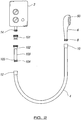
- shower apparatus including a water supply unit 2, a shower hose 4 and a shower head 6.
- the shower head 6 is provided with a standard male screw thread connector 8 which is received by the standard female screw thread connector 10 on one end of the shower hose 4.
- the other end of the shower hose is provided with a further standard female screw thread connector 12 which is adapted to fit the standard male screw thread connector 14 of the water supply unit 2.
- the antimicrobial or sterilisation applicator device 16 is fitted intermediate the shower hose 4 and water supply unit 2.
- the antimicrobial device 16 comprises a housing 18, and receiving means 20 which can be screwed on to the housing via screw thread 22 such that it extends therefrom.
- the housing 18 is provided with an inlet 32 provided with a standard male screw thread connector 34 and an outlet 36 provided with a standard male screw thread connector 38.
- the receiving means in this example is substantially circular in cross-section, and includes filtration means in the form of a concentric metal mesh 40, held in place by frictionally fitting to a protrusion 28.
- the mesh divides the receiving means into an inner portion 24 and an outer portion 26.
- the inner portion 24 of the receiving means, inside the mesh 40, is large enough to hold a sachet 54 containing an antimicrobial chemical such as Lonzabac 12.100 dissolved in hexylene glycol described in more detail below.
- the sachet is typically made from poly(vinyl alcohol) so that it dissolves when exposed to water.
- the sachet may alternatively contain a powder, which has the advantage that the sachet can be made from a thinner plastic film, which dissolves more rapidly and leaves less residue.
- liquid entering the inlet 32 flows into the inner portion 24, dissolves the sachet to release the chemical, forming a solution which is filtered through the mesh 40 into the outer portion 26, and then flows to the outlet 36.
- the mesh fits over a rim 52 of an orifice leading from the inlet, and the receiving means is provided with sealing means, in the form of a rubber seal 30 in this example, to prevent leaks.
- the antimicrobial applicator device in this example is provided with two male screw thread connectors 34, 38, to allow it to be connected to the water supply unit 2.
- An adapter 42 is also provided.
- the adapter 42 comprises a tube section 44 and two standard female screw thread connectors 46, 48 located at either end thereof, thereby allowing the antimicrobial applicator device to be connected to the water supply unit 2 via the adapter 42.
- the receiving means 103 is formed as part of the housing, in-line with the flow of water in the shower.
- the antimicrobial applicator device is provided with 'quick release' fittings 101, 102 allowing the device to be easily removed from the shower apparatus so that the chemical biocidal package can be placed therein above a mesh gauze 105 which acts as the filtration or screening means for filtering or retaining the PVA sachet until it dissolves completely.
- the housing 201 is Y-shaped and fitted directly onto a rigid delivery pipe in which the flow of liquid is upwardly direction from a water supply unit located below the shower head.
- One branch of the Y is in-line with the pipe (i.e. concentrically arranged), whereas the other branch is provided with a quick release fitting 202 and cap 203 allowing the receiving means 204 to be accessed for placement of a chemical therein, below a mesh gauze insert 205 which filters the liquid flow.
- a person disconnects the shower hose 4 from the water supply unit 2 and fits the antimicrobial applicator device 16 therebetween via the adapter 42.
- the system is flushed through with hot water for one to two minutes, then a sachet 54 of composition is placed inside the mesh 40 of the receiving means 20, and the receiving means is then screwed to the housing 18.
- the shower is switched on to allow water to flow through the antimicrobial applicator device 16, the water dissolving the sachet 54 to release the chemical and form a solution which flows through the mesh and to the outlet 36.
- the person runs the shower with the shower head in a raised position so that solution fills the hose 4, until solution comes out of the nozzles 50 of the shower head.
- the chemical may include a foaming agent so foam is visible at the shower head dispensing nozzles when the shower head is almost full of solution.
- the cleaning solution is allowed to stand for around 15 minutes, or other predetermined period according to the user's cleaning/disinfection/sterilisation requirements.
- the shower is then switched back on to flush the chemical out of the system.
- the chemical may be coloured so that the person can see when the liquid is free from chemical, when the water coming out of the shower head is clear.
- the antimicrobial applicator device does not need to be removed from the system after each use, and therefore on subsequent use the person can simply insert a new sachet of chemical and repeat the antimicrobial regime outlined above.
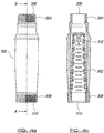
- Figures 4a-4b illustrate an example of a quick release in-line applicator device including an outer elongate sleeve housing 302 having a screw thread 308 provided at a first end 310 and a second screw thread 304 provided at a second end 306.
- Screw threads 304, 308 allow connection with complementary screw thread connections provided on or associated with the shower supply unit 2 and the shower hose 4, and the 'quick release' fitting 101/102 that joins thread 308 to the shower thread 14 in figure 2 .
- Receiving means in the form of a meshed basket 312 is provided in sleeve housing 302 to retain the PVA sachet containing the biocidal composition during the insertion and dissolution stage of the cleaning process.
- the water flow of the shower is typically stopped to allow the biocide rich solution to remain within the shower hose/head for the pre-defined contact time period.
- the shower is flushed through by switching the water flow in the shower back on and, in the intervening period, the remains of the sachet will have completely dissolved and can be removed from the system. It is clear when the flushing process is complete because the coloured dye contained in the composition disappears and foam from the bio-dispersants dissipates.
- the basket is removable from the sleeve housing, it is not necessary to remove it to allow insertion of the composition therein in use.
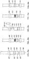
- Figures 5a-5e illustrate a further example of an in-line applicator device 402 that is located in place on the shower apparatus during fitting of the apparatus and does not require removal therefrom during a cleaning process.
- This applicator device 402 is particularly advantageous for use in fixed pipe or drain down shower systems where normal sterilisation is difficult without professional intervention being required to gain access to the areas of micro-biological growth and biofilm formation.
- the applicator device 402 is characterised by including a push fit design with a locking action to secure it in place. It is also tamper proof and no parts can be easily removed once fitted into the shower apparatus.
- Applicator device 402 includes an elongate body portion 403 including push fit locking connectors 408, 410 provided at opposite ends of device 402 for secure engagement with fixed shower pipes 404, 406 respectively.
- An aperture 411 is defined in body portion 403 to allow the location of a PVA sachet 414 therein in use during a cleaning process.
- a closure sleeve 412 is slidably mounted on the outer surface of body portion 403 and is movable between a closed position, wherein aperture 411 is closed by closure sleeve 412, and an open position, wherein aperture 411 is open and access to the aperture 411 can be gained by a user.
- a locking nut 416 has a screw thread on an internal surface thereof for engagement with a complementary screw thread 418 provided on body portion 403 below aperture 411. Locking nut 416 can be rotated via the screw threads in one direction to hold the closure sleeve in the closed position and can be rotated in the opposite direction to allow the closure sleeve to move away from the access opening to an open position.
- a non-return ball valve 420 is provided in body portion 403 towards end connector 410 to stop drain down of the pipe and shower head and allows the biocide rich solution to remain in contact with the wetted surfaces of the shower apparatus for the pre-defined sterilisation time.
- Filter means in the form of flat sieve members 422 are provided internally of body portion and substantially perpendicular to the direction of water flow to ensure the PVA sachet is retained in the applicator device prior to dissolution of the same.
- Figure 5a shows the applicator device 402 in a closed position located between two ends of fixed pipes 404, 406.
- Figure 5b shows the locking nut 416 being moved to a lowered position so that the closure sleeve 412 can be moved to an open position, as shown in figure 5c .
- Any water content present in the shower pipe and shower head are allowed to run back into the shower tray or bath via the access aperture 411.
- the PVA sachet containing the composition is inserted through aperture 411 in the device 402 and the closure sleeve member is then moved over the aperture 411 to the closed position to ensure no solution flows through the aperture 411 during the dissolution process, as shown in figure 5d .
- the locking nut 416 is moved back to a raised position so that the closure sleeve 412 is retained in the closed position and the device is substantially water tight, as shown in figure 5e .
- the shower apparatus is then switched on for a few seconds to allow hot water to fill the in-line device.
- the water flow is then stopped for approximately 30 seconds to allow the PVA to dissolve and release the composition therefrom.
- the shower apparatus is then switched on and water is allowed to flow through the shower at a low rate until all the coloured dye from the composition disappears.
- the shower apparatus is then switched on and water is allowed to flow through the shower at a low rate until the coloured dye appears at the shower head and then the water flow is stopped.
- the system is then allowed to rest for approximately 15 minutes. At the end of this rest period, the shower is switched on at a relatively high flow rate to allow the system to be flushed through for several minutes and to allow any foam to disperse.
- the shower apparatus is then ready for normal shower use.
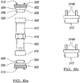
- Figure 6a shows examples of possible push fit connectors 502 that could be used with the in-line device 402 of figures 5a-5e to secure the device between the fixed shower pipes 404, 406.
- the fittings 502 can be adjusted to allow the fitment of the applicator device to various sizes of fixed pipe diameters, typically 15mm, 22mm, 25mm and the like.
- Connector 502 includes a body portion 504 having a first end 505 with locking lugs 506 that protrude outwardly from the body portion.
- the locking lugs 506, or threaded connections are pushed and twisted into complementary grooves or recesses defined on the interior surface of device connectors 408, 410.
- On the opposite second end 508 outwardly protruding locking members 510 are provided to engage with the interior surface of the fixed pipes 404, 406.
- Connector 512 is similar to connector 502 but outwardly protruding locking members 510 have been replaced by inwardly protruding engaging teeth 514.
- the teeth 514 A/B are designed to allow the applicator device to be inserted into the flexible shower hose as shown in fig.1 .
- the method of cleaning the shower apparatus includes the application of two separate compositions.
- the first composition is in the form of a packaged biocidal or sterilisation product.
- the second composition is in the form of a packaged acidic sequesterant which is designed to remove the 'biofilm' and the calcium carbonate/scale that accumulates on the interior surfaces of the shower apparatus in use over time and provides a roughened surface which act as a 'key' for the growth of microbes thereon.
- the acidic sequesterant is used in the shower apparatus before application of the biocidal or sterilisation composition (hereinafter referred to a biocidal composition).
- Both the first and second compositions are characterised by meeting all regulatory requirements on a worldwide basis, are capable of being blended with other components and can be handled by non-specialist operators.
- the first biocidal composition of the present invention includes a biocidal active component in the form of Bis-(3-aminopropyl)-dodecylamine which is commercially available under the trade name Lonzabac 12.100 (manufactured and distributed by Lonza AG).
- This biocidal composition is compatible for incorporation into a water soluble PVA sachet (i.e. is substantially or wholly non-aqueous).
- the biocidal component can be dissolved in a non-aqueous solution such as hexylene glycol to provide compatibility with the PVA sachet.
- the first biocidal composition also optionally includes one or more surface active bio-dispersants, a coloured dye (blue) and/or a fragrance.
- the biocidial composition of the present invention results in a fall in TVC from a starting level of approximately 10 5 cfu/ml to 20-500cfu/ ml.
- An example of the first biocidal general formulation includes: 1-5% N-(3-aminopropyl)-N-dodecylpropae-1,3,diamine 2-10% Alkyl alkoxylate 50-100% Alkylene glycol
- the second acidic sequestering composition includes Hydroxyl Ethylidene Di Phosphonic acid (H.E.D.P). In addition, a dispersion or wetting agent is included and a coloured dye (red). This acidic sequestering composition is compatible for incorporation into a water soluble PVA sachet (i.e. is substantially or wholly non-aqueous).
- An example of the second acidic sequestering composition includes:
- the Applicant has devised a sampling protocol to allow reproducible data to be obtained relating to the effectiveness of the composition.
- the Applicant has found that sampling water from a running shower to monitor existing microbiological activity within a shower is difficult. This is because any water sample taken from the shower water flow is significantly influenced by the free chlorine levels in the water flowing through the shower apparatus. These free chlorine levels are typically in the region of 0.6 to 0.8 ppm. In addition, sampling of aerosols that surround the flowing water has proven to be extremely difficult to achieve with any degree of reliability or repeatability.
- the biocidal composition of the present application can develop biocidal concentrations in the range of 300-600ppm in the wetted areas of the shower hose and head.
- the biocide was added to the pipe/shower head which was then completely filled with water. The contents were left for 60 minutes and then flushed out for a period of 5 minutes. The total volume (attachment/pipe/shower head) is 180mls - giving a biocide strength of 467ppm.
- Sample (1) 14.06.10 - Aerobic count. Dilution tubes used (100 & 1000x dilution applied) to provide a more accurate count. Subsequent tests on sample (1) after biocide addition - neat, 10x, 100x examined. DATE 14th June 2010 15th June 2010 16th June 2010 Analyses Water Halogen Content Mb. Analyses Halogen Content Mb. Analyses Halogen Content Mb.
- Table 2 shows how the microbiological activity has reestablished itself 8 days after treatment with the basic biocide solution, i.e. before the inclusion of the wetting agents and other functional components.
- Table 3 shows the effect of the introduction of the halogen release product BCDMH on the microbiological activity seen in the shower after 19 days resting. As can be seen, the microbiological recovery after two days is considerably greater than in the basic product results above.
- Table 4 shows the impact of the inclusion of the wetting agents and other components into the final formulation. As can be seen the microbiological 'count' after 48 hours still represents a sterile environment.
- Table 7 shows the impact of the increase in ambient temperature on the microbiological activity at time zero.
- the count of 1.36 x 10 6 colonies per millilitre is far higher than has been seen in any of the previous tests and is probably as a direct result of the increase in ambient temperature on the microbial activity.
- the average ambient temperature at this time was 14°C.
- the invention is also provided so that the cleaning treatment is quick and easy to perform on a regular basis.
- the samples were taken from shower apparatus in the en-suite facilities of ten bedrooms in a hotel local to the Applicant (with prior permission from the hotel owners obtained).
- Five of the bedrooms (Rooms 124, 133, 224, 324, 437) were treated using the biocide composition and procedure of the present invention as set out above and five of the bedrooms (Rooms 131, 231, 237, 330, 438) were treated using a conventional bleach treatment as outlined in the prior art HSE L8 procedure. All the showers tested used the protocol that has been developed by the Applicant and as set out herein (i.e. the shower hose of the apparatus is disconnected from the water supply or mixer unit and the contents of the shower hose and head drained down into a sterile container).
- sample 'A' sample The samples were taken prior to any treatment being applied (the 'A' sample) and after standing - 24 hours later (the 'C' sample).
- sample 'A' was taken after trickling water through the shower head and collecting the same in a sterile bottle.
- Sample C was taken 24 hours after each room had been treated by trickling water through the shower head and collecting the same in a sterile bottle.
- Samples were taken from each sterile container and placed in sterile tubes, sealed and transported to the third party analysts.
- Table 8 (also labelled Table 1) represent analyses carried out using a spiral plater technique for applying the samples to the plates.
- Tables 9-12 represent analyses carried out using the poured plate technique for applying the samples to the plates.
- the TVCs were measured on the plates after 2 days for plates kept at 37°C and after 3 days for plates kept at 22°C.
Landscapes
- Life Sciences & Earth Sciences (AREA)
- Health & Medical Sciences (AREA)
- Engineering & Computer Science (AREA)
- Public Health (AREA)
- General Health & Medical Sciences (AREA)
- Zoology (AREA)
- Pest Control & Pesticides (AREA)
- Environmental Sciences (AREA)
- Wood Science & Technology (AREA)
- Dentistry (AREA)
- Plant Pathology (AREA)
- Hydrology & Water Resources (AREA)
- Water Supply & Treatment (AREA)
- Agronomy & Crop Science (AREA)
- Chemical Kinetics & Catalysis (AREA)
- Animal Behavior & Ethology (AREA)
- Veterinary Medicine (AREA)
- General Chemical & Material Sciences (AREA)
- Chemical & Material Sciences (AREA)
- Epidemiology (AREA)
- Apparatus For Disinfection Or Sterilisation (AREA)
- Bathtubs, Showers, And Their Attachments (AREA)
- Agricultural Chemicals And Associated Chemicals (AREA)
- Nozzles (AREA)
- Devices For Medical Bathing And Washing (AREA)
Description
- The invention to which this application relates is a method of using a shower sterilisation system. In recent years there have been a number of high profile incidents where the spread of Legionnaires' disease in particular has caused great concern for public health and in some cases susceptible individuals have died as a result of contacting the disease (as for example reported on the BBC News website, at http://news.bbc.co.uk/go/pr/fr/-/l/hi/england/somerset/5256926.stm). The generally accepted mechanism for the spread of this disease is via the very fine particulate water mists/aerosols released from contaminated cooling towers or other facilities where aerosols can be produced and can contact personnel. A number of investigations have been carried out in the US and elsewhere to investigate the occurrence of microbiological contamination in domestic shower systems in particular and the presence of a number of potentially problematic species have been identified in a wide range of analyses from showers located in many different locations, and analyses carried out in the UK have yielded similar results.
- One species frequently identified is Mycobacterium avium which is a particularly difficult bacterium to kill under normal circumstances. In addition, there are a number of other bacterial species that have been identified as being transferred via the aerosol route, such as Legionella pneumophila, which can seriously aggravate respiratory diseases particularly in vulnerable members of the population.
- Whilst the exposure of the general public to aerosols from contaminated cooling towers will always be a potential issue, there are strict procedures laid down by the Health and Safety Executive (HSE) to treat, control, monitor, and report in a detailed manner all aspects of the treatment to control Legionella and other bacterial species in industrial cooling systems.
- However, another widespread potential problem area of exposure for the general public is the daily use of showers which, by definition, produce aerosols which can easily allow fine water particles to be introduced into the respiratory tracts of the individuals showering. In fact, HSE document L8 which summarises the procedures to be applied in the control of Legionella pneumophila acknowledges the risk from showers and recommends that all shower systems in commercial and industrial facilities are treated with a high level of halogen release product, such as chlorine dioxide, on a regular basis.
- Unfortunately the frequency proposed in the L8 guidelines of a quarterly treatment of each showerhead is largely influenced by the impracticality of the current procedure. In addition, it has been reported that Mycobacteria are resistance to chlorine treatment, possibly due to biofilm formation which provide protection to the bacteria from such treatment. The establishment of a bio-film on internal surfaces of shower apparatus is typically caused by a build up of calcium carbonate scale thereon from the water supply. The bacteria that are able to survive on this bio-film are rapidly re-inoculated back into any water that is left standing in the shower apparatus when the shower is not in use, such as in the shower hose or shower head. When the shower is switched back on, the bacteria are released in the water or as aerosols from the shower head. In particular, the aerosols are contaminated with particles of the biofilm containing the bacteria as a result of the biofilm being stripped from the internal surfaces of the apparatus caused by the turbulence of the water flowing through the apparatus.
- While it is possible to use more aggressive treatments against bacterial growth, in an industrial setting the guidelines suggest that the plant is shut down while disinfection takes place as typically chemicals are provided in the header tank so that the whole system can be flushed through. These procedures by their very nature are involved and time consuming and, as a result, the potential exists for them to be difficult to effectively supervise and control to ensure that the optimum performance is routinely achieved.
-
DE9016641 discloses a device for treating a stream of water in a pipe. The device includes a main channel through which the water flows and a mixing chamber adjacent to the main channel in which anti-bacterials or care agents can be located. Water is diverted from the main channel into the mixing chamber and then back into the main channel. -
FR2620470 -
US2002070293 discloses a shower filtration skin care device. The device is for joining to the threaded tube at the bottom of an existing hand held spray nozzle and the threaded orifice at the top of the nozzle hose. The device contains a filter and optionally can contain a skin care product. -
US6395172 discloses water purifying apparatus having a hollow container and a purifying material provided therein. The hollow container is disposed in a water channel. The purifying material contains a water soluble non-crystalline substance and activate carbon. -
US6647566 discloses an automatic bath additive feeder including an additive container defining an inner space, and a valve unit mounted on the container. -
US20070113892 discloses an apparatus for introducing additives into a fluid flow. An additive vessel, with chambers for one or more additives, is attached to a primary flow fixture in a configuration that allow part of the primary flow to be diverted through the additive vessel then back to the primary flow. The additive vessel can contain cleansing agents, moisturises or scent producing compositions. -
FR2264583 -
WO01/76647 -
WO00/69475 - As domestic showers have been shown to be the source of disease causing bacteria, and the currently available treatments are impractical, carried out too infrequently and/or are not effective in many situations (particularly the domestic environment), an aim of the present invention is to provide a shower sterilisation system that allows a simple and safe method of delivering an anti-microbial or sterilisation composition into shower apparatus to be established. A further aim of the invention is to establish a simple and effective method of cleaning shower apparatus to encourage frequent treatment of the apparatus using an anti-microbial or sterilisation composition, such that greater control of the build up of microbiological activity in the shower lines and head, and hence greater levels of overall protection, can be provided. The solution consists in the method of using a shower sterilisation system according to claim 1.
- The method of using a shower sterilisation system of the present invention allows a sterilisation or biocidal composition and an acid sequestering composition to be easily and effectively delivered to one or more parts of the shower apparatus to sterilise or clean the same. Using the acid sequestering composition prior to the sterilisation or biocidal composition allows to break up the biofilm protecting the bacteria within the system before attacking the bacteria. The later treatment with the sterilisation or biocidal composition thus becomes more efficient.
- Preferably the applicator device comprises a housing including inlet means and/or outlet means for allowing the flow of water from the shower apparatus therethrough in use.
- Preferably the applicator device includes receiving means located in or forming part of the housing for receiving the sterilisation composition in use.
- The housing and/or the receiving means of the applicator device preferably includes attachment means and/or access means to allow the composition to be placed in the receiving means in use.
- Preferably the inlet and/or outlet means are provided with connection means for allowing connection of the applicator device to the shower apparatus in use.
- The shower conduit means is typically any type of conduit, channel, tubing, hose, pipe and/or the like that allows water to flow therethrough from the water supply means to the shower head. The shower head is typically the portion of the shower apparatus from which the water is dispensed onto a user in use.
- The applicator device can be attached, detachably attached or integrally formed with the shower apparatus. An application device is used for delivering a composition to shower or fluid flow apparatus, said applicator device including;
a housing including inlet means and/or outlet means;
receiving means located in or forming part of the housing for receiving a composition in use;
the housing and/or the receiving means having attachment means and/or access means to allow the composition to be placed in the receiving means in use;
wherein the inlet and/or outlet means are provided with connection means for allowing connection of the applicator device to the shower or fluid flow apparatus in use. - The applicator device allows effective delivery of a composition for cleaning or treating fluid flowing through the apparatus or one or more interior surfaces of the shower apparatus, fluid flow apparatus or other apparatus with which it is connected to in use. The applicator device can be retrofitted to existing shower or fluid flow apparatus, can be integrally formed therewith, attached to detachably attached to and/or the like. The composition is a biocidal or sterilisation composition and an acidic sequestering composition. The receiving means defines an inner portion in fluid communication with an outer portion. Typically the inlet and outlet means are in respective fluid communication with the inner portion and the outer portion.
- Preferably the inner portion includes a mesh, one or more apertures and/or the like to allow fluid communication between the inner and outer portions of the receiving means. The receiving means can be in the form of a basket or container for containing or supporting the composition in use. Alternatively, the receiving means can be a cavity defined within the housing with delimiting means to separate the cavity of the receiving means from the remainder of the housing. The delimiting means can be filter means and/or the like. In either embodiment the basket, container or cavity is in fluid communication with the shower apparatus or fluid flow apparatus with which the applicator device is fitted to in use.
- The inlet and/or outlet means preferably include at least one opening defined therein for the flow of fluid therethrough in use. The inlet and outlet means can be provided separately or combined. The applicator device is typically in fluid communication with one or more parts of the shower apparatus. Preferably at least one fluid flow channel defined in the applicator device is substantially aligned with a fluid flow channel defined in the shower apparatus.
- Preferably the applicator device is located between the water supply unit and the shower conduit means of the shower apparatus. The applicator device is connected or provided substantially in-line with one or more parts of the shower apparatus through which fluid flows in use. Thus fluid or water flows from the water supply unit to the shower conduit means and head via the applicator device. The fluid flow allows any composition contained within the receiving means of the applicator device to be released into the water supply or fluid flow and pass out of the shower apparatus through the shower conduit and/or shower head.
Preferably the water flow channel of the applicator device and water flow channel of the part of the shower apparatus with which it is fitted to are substantially coaxially arranged. Thus, the longitudinal axis of the applicator device or channel defined in the applicator device is substantially parallel with and aligned with the longitudinal axis of the shower apparatus or channel defined in the shower apparatus with which it is connected to in use. - Typically one end of the shower conduit means is provided with a female screw thread for connection to a male screw thread on the water supply unit or means. Likewise, the shower head and the other end of the shower conduit means may be provided with opposite male/female screw threads to allow connection therebetween. The connection means include one or more screw threads extending from, provided on or associated with the housing of the applicator device.
- Preferably the screw threads of the connection means are both male, and therefore suitable for being received by the female screw thread of the shower conduit means to allow connection therebetween in use.
- The connection means could include any or any combination of one or more screw threads, friction fit, push fit and locking connection, inter-engaging members, one or more teeth, protruding lug or pin members, quick-release fittings, twist-lock connections and/or the like. The adapter means are provided to allow connection between the shower apparatus and the applicator device. The adapter means includes a tube or conduit provided with screw threads at one or both ends, such as for example female screw threads. Therefore the male screw thread of the applicator device in one embodiment can be connected to the male screw thread of the water supply unit via the adapter means.
- Preferably the adapter means engage the connection means of the applicator device to one or more parts of the shower or fluid flow apparatus in use.
- Typically the screw threads are configured to half-inch British Standard Pipe (BSP). The receiving means includes filtration means, typically capable of filtering the fluid flowing between the inner and outer portions or passing through the receiving means. Thus, the filtration means defines the inner and outer portions or delimiting means of the receiving means. The filtration means is a mesh, screen or gauze. Preferably the mesh or gauze is formed from plastic, metal or a metal based material. The filtration means extends or is arranged substantially perpendicular to the direction of fluid flow through the apparatus or to a central longitudinal axis defined through the aperture of the inlet and/or outlet means. Preferably the receiving means and/or housing is substantially circular in cross-section. Typically the filtration means is substantially concentric with the receiving means and/or channel defined through the housing of the applicator device through which fluid flows in use. The filtration means extends across at least a portion of the housing between the inlet and outlet means to filter liquid or fluid flowing therebetween. The housing is substantially Y-shaped or includes an outwardly protruding branch or arm portion from a main body portion to allow insertion of the composition therein in use. The branch or arm portion can be in fluid communication with the remainder of the housing or main body portion interior so that composition can pass into the water flowing through the housing in use.
- Typically the composition is locatable in the inner portion or cavity of the receiving means, such that the filtration means of the receiving means retains any insoluble material, such as for example any PVA material where used.
- Typically the applicator device is arranged to allow liquid or fluid to flow through the inlet means to the outlet means via the filtration means. Further typically in one embodiment the applicator device is arranged to allow liquid or fluid to flow through the inlet means into the inner portion, from the inner portion to the outer portion via the filtration means, and out from the outer portion via the outlet means. Liquid or fluid may then flow into a shower hose, conduit, pipe and/or the like connected to the outlet means. The receiving means is detachably connected to the housing via attachment means. The attachment means can include any or any combination of one or more screw threads, friction fit, inter-engaging members, one or more clips, ties, screws and/or the like. Thus the receiving means can be removed to insert, remove and/or replace the composition therein in use. The housing includes an access opening, and preferably in addition to one or more apertures of the inlet and/or outlet means, defined in a wall of the housing. The access opening allows user access to the interior of the housing and/or receiving means and preferably to the interior channel or cavity of the housing or receiving means through which fluid flows in use without having to remove the housing and/or receiving means from the apparatus. Preferably the composition can be located in the receiving means through the access opening of the housing.
- Preferably closure means are provided for closing the access opening in use. The closure means are typically movable between an open position, wherein access to the access opening is possible, and a closed position, wherein the access opening is closed.
- Preferably the closure means provides a substantially water tight sealing of the access opening when in a closed position to prevent fluid flowing through the applicator device from flowing through the access opening in the closed position.
- The closure means can be pivotably, rotatable, slidably movably mounted on the housing and/or the like to allow movement of the closure means between the open and closed positions. The closure means is slidably mounted on the housing and the closure means are maintained in the closed position by a rotatable nut or locking member. The closure means is a slidable sleeve member mounted on the housing.
- Preferably rotation of the nut or locking member in a direction away from the access opening allows the closure means to move from the closed position to an open position. Rotation of the nut or locking member in an opposite direction moves the closure means from an open position to a closed position.
- In upright or vertical hard piped systems fitted with 'drain down' facilities, the applicator device can be fitted with a non-return ball valve which enables a column of water to be maintained in the fixed pipe even when the water flow is stopped and the 'drain down' valve automatically opens. According to the invention, the applicator device is used for the delivery of a biocidal or sterilisation composition after delivery of an acid sequestering composition, into the shower apparatus or fluid flow apparatus.
- The composition for use with the applicator device can be in the form of a liquid, tablet, gel or powder. Typically the chemical composition is substantially soluble in water.
- In one embodiment the composition is contained within a container, sachet, capsule or bag.
- In one embodiment the container, sachet, capsule or bag is made of a soluble material, such as for example a soluble plastic material or film. Preferably the soluble material includes or comprises poly(vinyl alcohol or PVA).
- In one embodiment the chemical composition includes a chemical carrier and preferably the chemical carrier is substantially or wholly non-aqueous (preferably below 5% aqueous content and preferably 0% aqueous content), such that it does not result in dissolution of the soluble container material before the required time in one embodiment.
- In one embodiment the chemical carrier is or includes an alkylene glycol, such as hexylene glycol, in which the chemical may be soluble but the soluble plastic does not dissolve.
- Preferably the alkylene glycol is provided in an amount of between 10-100% by weight of the final composition, and further preferably 50-100%.
- Preferably the chemical composition includes any or any combination of antimicrobial, biocidal, descaling, chelating, sterilisation and/or other cleaning or treating components.
- The biocidal or sterilisation composition preferably includes a biocidal active component. Preferably the biocidal active component is N-(3-aminopropyl)-N-dodecylpropane-1,3-diamine (Lonzabac 12.100; CAS No. 2372-82-9; Lonza Ltd).
Lonzabac 12 is registered for use as a biocide in various countries including the UK, Europe, and the US at concentrations of 0.5%, and is effective against Legionella, Mycobacteria, Hepatatis and HIV down to concentrations of 0.05%. - Preferably the biocidal active component is used in the composition in an amount of 1-5% by weight of the final composition.
- Preferably the biocidal or sterilisation composition includes an alkyl alkoxylate. Preferably the alkyl alkoxylate is used in the composition in an amount of 2-10% by weight of the final composition. The alkyl alkoxylate typically acts as a wetting agent. Other wetting agents could be used.
- The acid sequestering composition is for removing calcium carbonate or precipitated hardness scale from the interior surfaces of the fluid flow apparatus or shower apparatus. This contributes to the removal of or cleaning of the 'key' to which a 'bio-film' layer may successfully adhere and build up. Preferably the composition includes an acid or organic acid, such as for example phosphonic acid.
- Preferably the acid is used in the composition in an amount of 2-10% by weight of the final composition.
- Preferably the acid sequestering composition includes an alkyl alkoxylate. Preferably the alkyl alkoxylate is used in the composition in an amount of 2-10% by weight of the final composition. The alkyl alkoxylate typically acts as a wetting agent. Other wetting agents could be used.
- In one embodiment the container, sachet, capsule or bag contains around 1-20ml of liquid composition, and typically around 4-10ml of liquid composition. It will be appreciated that the volume of composition used can be varied according to the circumstances.
- Typically the composition is provided at a concentration of around 0.1-10% but preferably around 1%. As a shower head and shower conduit means usually have volumes of around 100-400ml, this typically provides a concentration of approximately 200-500ppm when the chemical composition is diluted in water or other liquid filling the shower head and conduit means. It will be appreciated that the concentration of chemical composition can be adjusted to suit the user's systems.
- Typically the chemical composition includes any or any combination of one or more foaming and/or wetting agents. This assists in the penetration of the bio-film by the antimicrobial active component and/or other components of the chemical composition.
- In one embodiment the chemical composition includes a dye and/or fragrance. The dye typically provides or forms a coloured solution when the composition is dissolved in the water flow. Thus a user can visually detect when the shower apparatus or fluid flow apparatus is being treated with the chemical composition.
- Preferably the method includes the step of allowing water to flow through the shower apparatus to cause said sterilisation or biocidal composition to be delivered to the one or more parts of the shower apparatus in use.
- Preferably the chemical solution is allowed to stand or rest for a pre-determined period of time within the shower apparatus or fluid flow apparatus to allow any active ingredients of the chemical solution to take affect.
In one embodiment the predetermined time is based on the following expression:
- E
- = The effectiveness of the biocide molecule against the target bacteria
- CC
- = The contact concentration of the biocidal active component in the system
- CT
- = The contact time of the formulation in the system
- pH
- = The pH in the system
- T
- = The temperature of the system
- In one embodiment the chemical solution is allowed to stand for between 5-60 minutes. Preferably the chemical solution is allowed to stand for approximately 15 minutes.
- Preferably the chemical solution is flushed out or washed out from the shower apparatus or fluid flow apparatus by allowing fluid or water to flow through the apparatus again for a pre-determined period of time following the standing time.
- In one embodiment the chemical composition is placed in an inner portion of the receiving means, such that liquid flows from the inner portion to the outlet means via an outer portion of the receiving means.
- In one embodiment the chemical composition is provided in a container, sachet, bag or capsule that dissolves on application of liquid or water thereto.
- In one embodiment any remains of the container, sachet, bag or capsule following liquid or water application is retained in the receiving means by the filtration means located between the inner and outer portions of the receiving means.
- In one embodiment the shower conduit means is substantially filled up with liquid or water in which the chemical composition is substantially dissolved. Typically the shower head is also substantially filled with the chemical solution.
- In an alternative embodiment the chemical solution is allowed to stand in the shower conduit means for a predetermined period of time, typically around one hour in one example. Preferably the stand time in one embodiment is 15 minutes.
- Typically the shower is run hot or warm (i.e. at a temperature above normal mains water supply temperature) for a pre-determined period of time, such as for example around two minutes, before the chemical composition is added into the applicator device.
- Typically the shower apparatus is flushed through with water or other liquid for around one to two minutes after the chemical solution has been allowed to stand for the predetermined period. This ensures that all traces of the treatment chemicals are removed before the shower is returned to service. This status is reached when all traces of the coloured dye and the foam generated by the wetting agents have completely disappeared from the shower spray and base.
- Thus, in one embodiment, the invention provides a practical approach to the in-situ sterilisation of shower apparatus via the use of a detachable or permanently attached in-line device used in conjunction with a specific chemical treatment as defined in claim 1, which is designed to control microbiological activity typically in the shower conduit means and shower distribution head of the shower apparatus.
- The introduction of a simple, reliable and easy to operate individual shower sterilisation system provides the opportunity for extensive, systematic control of a current potentially serious threat to public health. This system could easily be integrated into standard cleaning programmes in hospitals, hotels, sports facilities, schools, prisons, detention centres, universities and into every home in the country. The potential beneficial impact on this proven route for problematic microbiological species to threaten public health could be very significant indeed.
- Specific embodiments of the invention are now described wherein:-
-
Figure 1 illustrates an exploded schematic view of a shower system including an antimicrobial or sterilisation applicator device. -
Figure 2 illustrates an exploded schematic view of a shower system including an antimicrobial or sterilisation applicator device. -
Figure 3 illustrates a view of a shower system including an antimicrobial or sterilisation applicator device. -
Figure 4a illustrates an external side view of an applicator device andFigure 4b illustrates a cross sectional view taken along line A-A of the applicator device inFigure 4a . -
Figures 5a-5e illustrate an in-line applicator device 402 that is located in place on the shower apparatus during fitting of the apparatus and does not require removal therefrom during a cleaning, sterilisation or disinfecting process. -
Figures 6a and 6b show examples of possible push fit connectors that could be used with the in-line device shown infigures 5a-5e to secure the device between fixed shower pipes. - The Applicants have designed a number of devices to allow the introduction of a biocidal or sterilisation composition and acidic sequestering composition into the shower apparatus. The compositions are preferably introduced into the shower hose and head of the apparatus downstream of the water control valve(s) of the apparatus.
- With reference to
Figure 1 , there is illustrated shower apparatus including awater supply unit 2, a shower hose 4 and ashower head 6. - The
shower head 6 is provided with a standard malescrew thread connector 8 which is received by the standard femalescrew thread connector 10 on one end of the shower hose 4. Similarly, the other end of the shower hose is provided with a further standard femalescrew thread connector 12 which is adapted to fit the standard malescrew thread connector 14 of thewater supply unit 2. - However, according to one example, the antimicrobial or sterilisation applicator device 16 is fitted intermediate the shower hose 4 and
water supply unit 2. - The antimicrobial device 16 comprises a housing 18, and receiving means 20 which can be screwed on to the housing via
screw thread 22 such that it extends therefrom. - The housing 18 is provided with an
inlet 32 provided with a standard malescrew thread connector 34 and anoutlet 36 provided with a standard malescrew thread connector 38. - The receiving means in this example is substantially circular in cross-section, and includes filtration means in the form of a
concentric metal mesh 40, held in place by frictionally fitting to aprotrusion 28. The mesh divides the receiving means into aninner portion 24 and anouter portion 26. - The
inner portion 24 of the receiving means, inside themesh 40, is large enough to hold asachet 54 containing an antimicrobial chemical such as Lonzabac 12.100 dissolved in hexylene glycol described in more detail below. The sachet is typically made from poly(vinyl alcohol) so that it dissolves when exposed to water. - Rather than a solution, the sachet may alternatively contain a powder, which has the advantage that the sachet can be made from a thinner plastic film, which dissolves more rapidly and leaves less residue.
- Thus when the receiving means 20 is connected to the housing 18, liquid entering the
inlet 32 flows into theinner portion 24, dissolves the sachet to release the chemical, forming a solution which is filtered through themesh 40 into theouter portion 26, and then flows to theoutlet 36. The mesh fits over arim 52 of an orifice leading from the inlet, and the receiving means is provided with sealing means, in the form of arubber seal 30 in this example, to prevent leaks. - The antimicrobial applicator device in this example is provided with two male
screw thread connectors water supply unit 2. Anadapter 42 is also provided. - The
adapter 42 comprises atube section 44 and two standard femalescrew thread connectors water supply unit 2 via theadapter 42. - With reference to
Figure 2 , in a second example the receiving means 103 is formed as part of the housing, in-line with the flow of water in the shower. The antimicrobial applicator device is provided with 'quick release'fittings mesh gauze 105 which acts as the filtration or screening means for filtering or retaining the PVA sachet until it dissolves completely. - With reference to
Figure 3 , a yet further example is illustrated, wherein thehousing 201 is Y-shaped and fitted directly onto a rigid delivery pipe in which the flow of liquid is upwardly direction from a water supply unit located below the shower head. One branch of the Y is in-line with the pipe (i.e. concentrically arranged), whereas the other branch is provided with a quick release fitting 202 andcap 203 allowing the receiving means 204 to be accessed for placement of a chemical therein, below amesh gauze insert 205 which filters the liquid flow. - Thus for the first time use, as shown in
figure 1 , a person disconnects the shower hose 4 from thewater supply unit 2 and fits the antimicrobial applicator device 16 therebetween via theadapter 42. - The system is flushed through with hot water for one to two minutes, then a
sachet 54 of composition is placed inside themesh 40 of the receiving means 20, and the receiving means is then screwed to the housing 18. - The shower is switched on to allow water to flow through the antimicrobial applicator device 16, the water dissolving the
sachet 54 to release the chemical and form a solution which flows through the mesh and to theoutlet 36. The person runs the shower with the shower head in a raised position so that solution fills the hose 4, until solution comes out of thenozzles 50 of the shower head. The chemical may include a foaming agent so foam is visible at the shower head dispensing nozzles when the shower head is almost full of solution. - The cleaning solution is allowed to stand for around 15 minutes, or other predetermined period according to the user's cleaning/disinfection/sterilisation requirements.
- The shower is then switched back on to flush the chemical out of the system. The chemical may be coloured so that the person can see when the liquid is free from chemical, when the water coming out of the shower head is clear.
- If the sachet has not fully dissolved, it is straightforward to disconnect the receiving means, take out the filter, and wash any remaining residue off the same.
- The antimicrobial applicator device does not need to be removed from the system after each use, and therefore on subsequent use the person can simply insert a new sachet of chemical and repeat the antimicrobial regime outlined above.
- The HSE L8 guidelines suggest that showers are disinfected using a halogen release product such as 1-Bromo-3-chloro-5,5-dimethylhydantoin (BCDMH). However, in comparative tests it has been found that using the invention as described, wherein a solution of around 250-500ppm Lonzabac 12.100 is created and used in the manner described above, a more effective sterilisation was achieved for a longer period than was achieved using 5parts per million of BCDMH in the manner prescribed in the L8 recommendations.
-
Figures 4a-4b illustrate an example of a quick release in-line applicator device including an outerelongate sleeve housing 302 having ascrew thread 308 provided at afirst end 310 and asecond screw thread 304 provided at asecond end 306.Screw threads shower supply unit 2 and the shower hose 4, and the 'quick release' fitting 101/102 that joinsthread 308 to theshower thread 14 infigure 2 . - Receiving means in the form of a
meshed basket 312 is provided insleeve housing 302 to retain the PVA sachet containing the biocidal composition during the insertion and dissolution stage of the cleaning process. As soon as the solution of the biocide flows through the shower head, the water flow of the shower is typically stopped to allow the biocide rich solution to remain within the shower hose/head for the pre-defined contact time period. Once the pre-defined contact time has been reached, the shower is flushed through by switching the water flow in the shower back on and, in the intervening period, the remains of the sachet will have completely dissolved and can be removed from the system. It is clear when the flushing process is complete because the coloured dye contained in the composition disappears and foam from the bio-dispersants dissipates. - Although the basket is removable from the sleeve housing, it is not necessary to remove it to allow insertion of the composition therein in use.
-
Figures 5a-5e illustrate a further example of an in-line applicator device 402 that is located in place on the shower apparatus during fitting of the apparatus and does not require removal therefrom during a cleaning process. Thisapplicator device 402 is particularly advantageous for use in fixed pipe or drain down shower systems where normal sterilisation is difficult without professional intervention being required to gain access to the areas of micro-biological growth and biofilm formation. Theapplicator device 402 is characterised by including a push fit design with a locking action to secure it in place. It is also tamper proof and no parts can be easily removed once fitted into the shower apparatus. -
Applicator device 402 includes anelongate body portion 403 including push fit lockingconnectors device 402 for secure engagement with fixedshower pipes 404, 406 respectively. Anaperture 411 is defined inbody portion 403 to allow the location of aPVA sachet 414 therein in use during a cleaning process. Aclosure sleeve 412 is slidably mounted on the outer surface ofbody portion 403 and is movable between a closed position, whereinaperture 411 is closed byclosure sleeve 412, and an open position, whereinaperture 411 is open and access to theaperture 411 can be gained by a user. A lockingnut 416 has a screw thread on an internal surface thereof for engagement with acomplementary screw thread 418 provided onbody portion 403 belowaperture 411. Lockingnut 416 can be rotated via the screw threads in one direction to hold the closure sleeve in the closed position and can be rotated in the opposite direction to allow the closure sleeve to move away from the access opening to an open position. - A
non-return ball valve 420 is provided inbody portion 403 towardsend connector 410 to stop drain down of the pipe and shower head and allows the biocide rich solution to remain in contact with the wetted surfaces of the shower apparatus for the pre-defined sterilisation time. Filter means in the form offlat sieve members 422 are provided internally of body portion and substantially perpendicular to the direction of water flow to ensure the PVA sachet is retained in the applicator device prior to dissolution of the same. -
Figure 5a shows theapplicator device 402 in a closed position located between two ends of fixedpipes 404, 406.Figure 5b shows the lockingnut 416 being moved to a lowered position so that theclosure sleeve 412 can be moved to an open position, as shown infigure 5c . Any water content present in the shower pipe and shower head are allowed to run back into the shower tray or bath via theaccess aperture 411. The PVA sachet containing the composition is inserted throughaperture 411 in thedevice 402 and the closure sleeve member is then moved over theaperture 411 to the closed position to ensure no solution flows through theaperture 411 during the dissolution process, as shown infigure 5d . The lockingnut 416 is moved back to a raised position so that theclosure sleeve 412 is retained in the closed position and the device is substantially water tight, as shown infigure 5e . - The shower apparatus is then switched on for a few seconds to allow hot water to fill the in-line device. The water flow is then stopped for approximately 30 seconds to allow the PVA to dissolve and release the composition therefrom. The shower apparatus is then switched on and water is allowed to flow through the shower at a low rate until all the coloured dye from the composition disappears. The shower apparatus is then switched on and water is allowed to flow through the shower at a low rate until the coloured dye appears at the shower head and then the water flow is stopped. The system is then allowed to rest for approximately 15 minutes. At the end of this rest period, the shower is switched on at a relatively high flow rate to allow the system to be flushed through for several minutes and to allow any foam to disperse. The shower apparatus is then ready for normal shower use.
-
Figure 6a shows examples of possible pushfit connectors 502 that could be used with the in-line device 402 offigures 5a-5e to secure the device between the fixedshower pipes 404, 406. As can be seen infig. 6a , thefittings 502 can be adjusted to allow the fitment of the applicator device to various sizes of fixed pipe diameters, typically 15mm, 22mm, 25mm and the like. -
Connector 502 includes abody portion 504 having afirst end 505 with lockinglugs 506 that protrude outwardly from the body portion. The locking lugs 506, or threaded connections are pushed and twisted into complementary grooves or recesses defined on the interior surface ofdevice connectors second end 508 outwardly protruding lockingmembers 510 are provided to engage with the interior surface of the fixedpipes 404, 406. -
Connector 512 is similar toconnector 502 but outwardly protruding lockingmembers 510 have been replaced by inwardly protruding engaging teeth 514. Theteeth 514 A/B are designed to allow the applicator device to be inserted into the flexible shower hose as shown infig.1 . - The method of cleaning the shower apparatus includes the application of two separate compositions. The first composition is in the form of a packaged biocidal or sterilisation product. The second composition is in the form of a packaged acidic sequesterant which is designed to remove the 'biofilm' and the calcium carbonate/scale that accumulates on the interior surfaces of the shower apparatus in use over time and provides a roughened surface which act as a 'key' for the growth of microbes thereon. The acidic sequesterant is used in the shower apparatus before application of the biocidal or sterilisation composition (hereinafter referred to a biocidal composition).
The fall in TVCs or "kill" of the micro-activity following use of the first biocidal product alone or following a combination of use of the first biocidal product and second acidic sequestering product is similar but the time before significant re-inoculation is extended when the combination of the first and second compositions are used. In areas of high water hardness, the potential for re-inoculation is much higher than in areas of low water hardness and therefore the benefit of using an acidic sequestering product in combination with the biocidal product is much higher. - Both the first and second compositions are characterised by meeting all regulatory requirements on a worldwide basis, are capable of being blended with other components and can be handled by non-specialist operators.
- The first biocidal composition of the present invention includes a biocidal active component in the form of Bis-(3-aminopropyl)-dodecylamine which is commercially available under the trade name Lonzabac 12.100 (manufactured and distributed by Lonza AG). This biocidal composition is compatible for incorporation into a water soluble PVA sachet (i.e. is substantially or wholly non-aqueous). For example, the biocidal component can be dissolved in a non-aqueous solution such as hexylene glycol to provide compatibility with the PVA sachet.
- The first biocidal composition also optionally includes one or more surface active bio-dispersants, a coloured dye (blue) and/or a fragrance.
- The biocidial composition of the present invention results in a fall in TVC from a starting level of approximately 105cfu/ml to 20-500cfu/ ml.
- An example of the first biocidal general formulation includes: 1-5% N-(3-aminopropyl)-N-dodecylpropae-1,3,diamine
2-10% Alkyl alkoxylate
50-100% Alkylene glycol - The second acidic sequestering composition includes Hydroxyl Ethylidene Di Phosphonic acid (H.E.D.P). In addition, a dispersion or wetting agent is included and a coloured dye (red). This acidic sequestering composition is compatible for incorporation into a water soluble PVA sachet (i.e. is substantially or wholly non-aqueous).
- An example of the second acidic sequestering composition includes:
- 2-10% phosphonic acid
- 2-10% Alkyl alkoxylate
- 50-100% Alkylene glycol
- In order to test the effectiveness of the cleaning and/or disinfecting composition of the present invention, the Applicant has devised a sampling protocol to allow reproducible data to be obtained relating to the effectiveness of the composition.
- The Applicant has found that sampling water from a running shower to monitor existing microbiological activity within a shower is difficult. This is because any water sample taken from the shower water flow is significantly influenced by the free chlorine levels in the water flowing through the shower apparatus. These free chlorine levels are typically in the region of 0.6 to 0.8 ppm. In addition, sampling of aerosols that surround the flowing water has proven to be extremely difficult to achieve with any degree of reliability or repeatability.
- Thus, in order to provide an effective method of monitoring microbiological activity in a given shower system, the Applicant has devised the following approach for use in one embodiment:
- 1. Prior to implementation of any cleaning procedure, the shower hose is disconnected at the mixer device and the contents of the hose and head are allowed to run back into a sterile container.
- 2. The period of time since the shower has been used in noted.
- 3. The sample taken in the sterile container is tested immediately in order to minimise the potential for the microbiological activity to be influenced by a) time, b) temperature changes in transport, or c) microbiological population shifts as a result of the absence of air in the sample container or the level of food source vs the microbiological population present.
- 4. At least 24 hours after any treatment takes place, a repeat sample is taken as described above. The shower is routinely run for three minutes following the taking of the sample and re-connection of the hose in order to simulate normal use of the shower.
- 5. Subsequent samples are taken in the same way at roughly 24 hour intervals, except where a long term standing study has been carried out.
- Samples taken during the early stages of the development of the present invention were analysed for Total Viable Counts using either dip slides - at remote sampling locations, or Petri-Films in local locations where laboratory facilities were available. Subsequently, extensive analyses have been carried out by third party analysts where 'full differential' analyses have been carried out. In one embodiment of the present invention there is provided a method of sampling shower apparatus.
- Substantial testing, treatment and analysis of shower systems in a test facility have been carried out and a summary of the results achieved are shown below. It has been found that on standing for a period of days a typical microbiological 'count' taken on a sample of water at the beginning of the shower period can be around 105 colonies per millilitre. In fact it has also been noted, as shown in the following tables, that as the ambient temperature increased during the early summer period, this level of contamination increased up to in excess of 106 colonies per millilitre of shower water.
- The following tables show that despite the very high levels of microbial contamination established in the shower system prior to the introduction of the treatment regime, as described above, the microbiological count in the days subsequent to the use of the chemical treatment programme produced a dramatic reduction to almost complete sterility for a number of days following the treatment. Since it is intended that the chemical treatment described is used on a weekly basis it is therefore quite conceivable that the spread of disease from this source could be completely eradicated with the adherence to a very simple and easy to administer programme.
- On the basis of a typical flexible shower hose length used in UK shower systems, the biocidal composition of the present application can develop biocidal concentrations in the range of 300-600ppm in the wetted areas of the shower hose and head.
- Results using a Bis-(3-aminopropyl)-dodecylamine active in the composition of the present invention against Legionella Pneumophilia at the Eurofins Laboratory in Milan, using the latest BS EN 13623 protocol, confirmed that the biocidal active in the composition is biocidal to Legionella at all concentrations in a short a contact time as 5 minutes. See Table A below.
Concentration of Biocidal Active: Contact time: 5 Minutes: 10 Minutes: 15 Minutes: 30 minutes: 100 ppm Biocidal Biocidal Biocidal Biocidal 200 ppm Biocidal Biocidal Biocidal Biocidal 300 ppm Biocidal Biocidal Biocidal Biocidal 500 ppm Biocidal Biocidal Biocidal Biocidal - However, it is the recommendation of the Applicant that the shower system is left to soak for approximately 15 minutes before flushing the contents of the shower apparatus with water to ensure that the microbiological-activity in the apparatus has been reduced sufficiently.

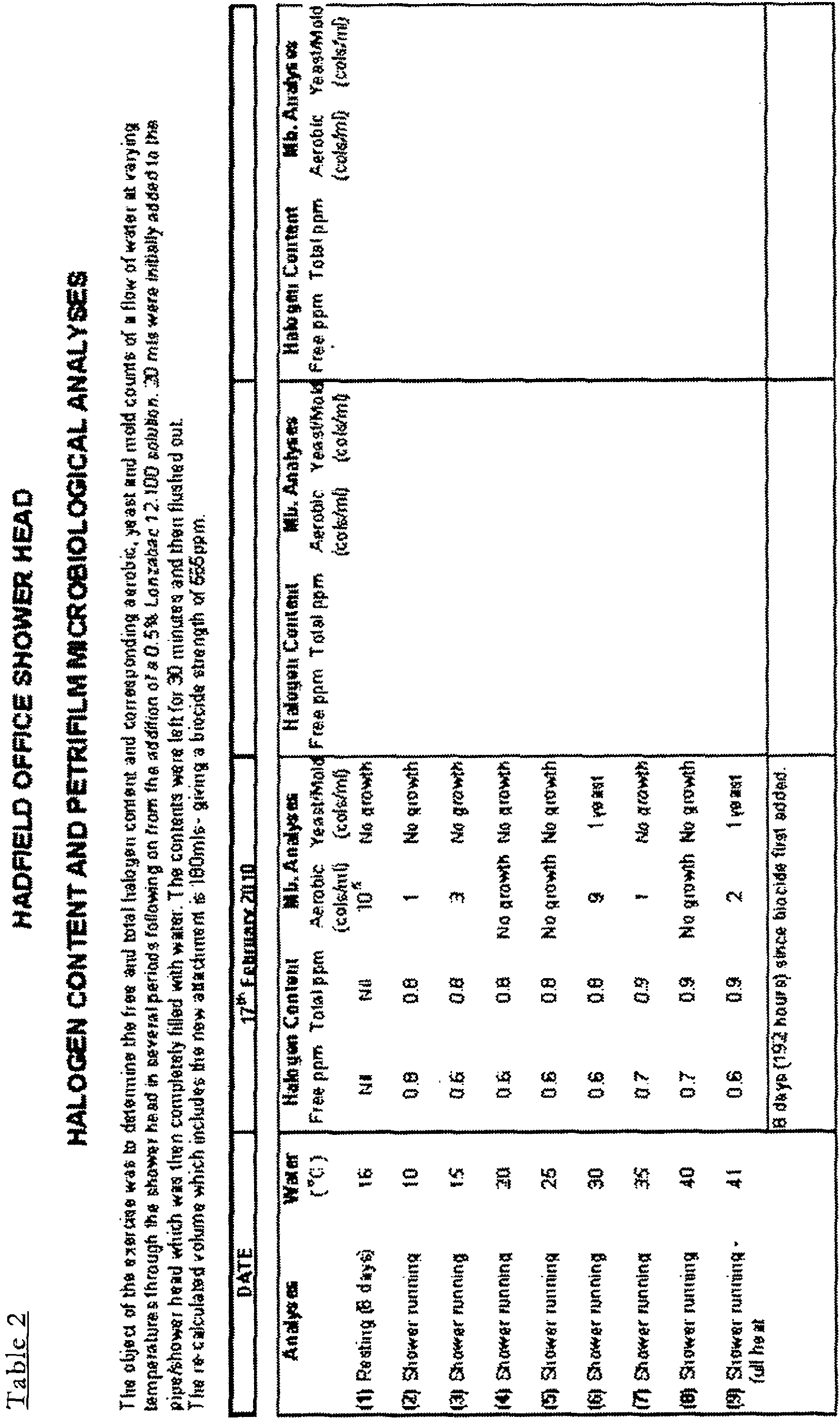
Table 3 HADFIELD OFFICE SHOWER HEAD HALOGEN CONTENT AND PETRIFILM MICROBIOLOGICAL ANALYSES The object of the exercise was to determine the free and total halogen content and corresponding aerobic, yeast and mold counts of a flow of water at varying temperatures through the shower head in several periods following on from the addition of an oxidising biocide - 0.05% Omnia-Stat SP (BCDMH) solution. 1.8mls (diluted to 20mls). were added to the pipe/shower head which was then completely filled with water.The contents were left for 30 minutes and then flushed out. The re-calculated volume which includes the new attachment is 180mls - giving a biocide strength of 5ppm (halogen in shower head measured 4ppm). DATE 16th March 2010 17th March 2010 18th March 2010 Analyses Water Halogen Content Mb. Analyses Halogen Content Mb. Analyses Halogen Content Mb. Analyses (°C) Free ppm Total ppm Aerobic (cols/ml) Yeast/Mold (cols/ml) Free ppm Total ppm Aerobic (cols/ml) Yeast/Mold (cols/ml) Free ppm Total ppm Aerobic (cols/ml) Yeast/Mold (cols/ml) (1) Resting (19 days) 17 Nil Nil 5x10⁴ 5 yeast Nil 0.05 480 No growth Nil Nil 2600 9 yeast (2) Shower running 10 0.7 0.9 No growth 2 yeast 0.6 0.9 No growth No growth 0.7 0.8 3 8 yeast (3) Shower running 15 0.7 0.9 No growth 2 yeast 0.6 0.9 1 No growth 0.7 0.9 3 6 yeast (4) Shower running 20 0.6 0.9 No growth No growth 0.6 0.9 5 4 yeast 0.6 0.9 5 19 yeast (5) Shower running 25 0.7 0.9 No growth No growth 0.7 0.9 10 7 yeast 0.6 0.8 9 No growth (6) Shower running 30 0.7 0.9 No growth No growth 0.7 0.9 5 3 yeast 0.6 0.8 2 6 yeast (7) Shower running 35 0.6 0.8 No growth No growth 0.7 0.9 6 5 yeast 0.7 0.9 10 No growth (8) Shower running 40 0.6 0.8 No growth No growth 0.8 0.9 No growth No growth 0.6 0.8 6 10 yeast (9) Shower running - full heat 42 0.6 0.8 No growth No growth 0.7 0.9 No growth No growth 0.6 0.8 No growth 5 yeast After tests (1 to 9) completed, biocide added at 5ppm. for a duration of 30 minutes and then flushed out. Resting temp. 18°C. 24 hours after biocide addition. Full heat 43°C Resting temp. 17°C. 48 hours after biocide addition. Full heat 42°CTable 4 HADFIELD OFFICE SHOWER HEAD HALOGEN CONTENT AND PETRIFILM MICROBIOLOGICAL ANALYSES The object of the exercise was to determine the free and total halogen content and corresponding aerobic, yeast and mold counts of a flow of water at varying temperatures through the shower head in several periods following on from the addition of a 7g form Shower Sanitiser 1 (BAC). 7mls of neat solution - 1% active (diluted to 20mls). were added to the pipe/shower head which was then completely filled with water.The contents were left for 30 minutes and then flushed out. The re-calculated volume which includes the new attachment is 180mls - giving a biocide strength of 389ppm. DATE 23rd March 2010 24th March 2010 25th March 2010 Analyses Water Halogen Content Mb. Analyses Halogen Content Mb. Analyses Halogen Content Mb. Analyses (°C) Free ppm Total ppm Aerobic (cols/ml) Yeast/Mold (cols/ml) Free ppm Total ppm Aerobic (cols/ml) Yeast/Mold (cols/ml) Free ppm Total ppm Aerobic (cols/ml) Yeast/Mold (cols/ml) (1) Resting (5 days) 19 Nil Nil 106 No growth 0.05 0.1 16 No growth Nil 0.05 35 No growth (2) Shower running 10 0.8 0.9 100 No growth 0.6 0.8 No growth No growth 0.6 0.8 No growth No growth (3) Shower running 15 0.8 0.9 150 No growth 0.6 0.8 No growth No growth 0.6 0.8 No growth No growth (4) Shower running 20 0.8 0.9 No growth No growth 0.6 0.8 2 6 yeast 0.6 0.8 2 4 yeast (5) Shower running 25 0.7 0.8 No growth No growth 0.6 0.8 9 6 yeast 0.6 0.8 No growth No growth (6) Shower running 30 0.7 0.8 No growth No growth 0.6 0.8 1 No growth 0.6 0.8 1 No growth (7) Shower running 35 0.7 0.8 3 No growth 0.6 0.8 No growth 1 yeast 0.6 0.8 1 No growth (8) Shower running 40 0.7 0.8 No growth No growth 0.6 0.8 1 No growth 0.6 0.8 No growth 8 yeast (9) Shower running - full heat 42 0.7 0.8 1 No growth 0.6 0.8 No growth No growth 0.6 0.8 2 No growth After tests (1 to 9) completed, biocide added at 389ppm. for a duration of 30 mins and then flushed out (very foamy). Resting temp. 18°C. 24 hours after biocide addition. Full heat 44°CResting temp. 18°C. 48 hours after biocide addition. Full heat 42°CTable 5 HADFIELD OFFICE SHOWER HEAD HALOGEN CONTENT AND PETRIFILM MICROBIOLOGICAL ANALYSES The object of the exercise was to determine the free and total halogen content and corresponding aerobic, yeast and mold counts of a flow of water at varying temperatures through the shower head in several periods following on from the addition of a 7g form Shower Sanitiser 1 (BAC). 7mls of neat solution -1% active (diluted to 20mls). were added to the pipe/shower head which was then completely filled with water.The contents were left for 60 minutes and then flushed out. The re-calculated volume which includes the new attachment is 180mls - giving a biocide strength of 389ppm. DATE 19th April 2010 20th April 2010 21st April 2010 Analyses Water Halogen Content Mb. Analyses Halogen Content Mb. Analyses Halogen Content Mb. Analyses (°C) Free ppm Total ppm Aerobic (cols/ml) Yeast/Mold (cols/ml) Free ppm Total ppm Aerobic (cols/ml) Yeast/Mold (cols/ml) Free ppm Total ppm Aerobic (cols/ml) Yeast/Mold (cols/ml) (1) Resting (12 days) 19 Nil Nil 105 No growth Nil 0.05 No growth No growth Nil 0.05 400 1 (2) Shower running 10 0.7 0.8 135 No growth 0.6 0.8 2 No growth 0.6 0.8 No growth No growth (3) Shower running 15 0.6 0.8 2 No growth 0.6 0.8 No growth No growth 0.6 0.8 No growth 3 (4) Shower running 20 0.6 0.8 No growth No growth 0.6 0.8 1 No growth 0.6 0.8 3 No growth (5) Shower running 25 0.6 0.8 No growth No growth 0.6 0.8 No growth No growth 0.6 0.8 6 No growth (6) Shower running 30 0.6 0.8 5 No growth 0.6 0.8 No growth No growth 0.6 0.8 6 No growth (7) Shower running 35 0.6 0.8 No growth No growth 0.6 0.8 No growth No growth 0.6 0.8 No growth No growth (8) Shower running 40 0.6 0.8 4 No growth 0.6 0.8 1 No growth 0.6 0.8 9 No growth (9) Shower running - full heat 45 0.6 0.8 No growth No growth 0.6 0.8 No growth No growth 0.6 0.8 6 No growth After tests (1 to 9) completed, biocide added at 389ppm. for a duration of 60 mins and then flushed out (very foamy). Resting temp. 17°C. 24 hours after biocide addition. Full heat 44°CResting temp. 17°C. 48 hours after biocide addition. Full heat 44°CTable 6 HADFIELD OFFICE SHOWER HEAD HALOGEN CONTENT AND PETRIFILM MICROBIOLOGICAL ANALYSES The object of the exercise was to determine the aerobic, yeast and mold counts of a flow of water at varying temperatures through the shower head in several periods following on from the addition of 8.4 mls, diluted to 20mls, of Shower Sanitiser 3 ( 1% active ). The biocide was added to the pipe/shower head which was then completely filled with water.The contents were left for 60 minutes and then flushed out. The total volume (attachment/pipe/shower head) is 180mls - giving a biocide strength of 467ppm. Sample (1) 26.05.10 - Aerobic count. Dilution tubes used (100, 1000 &10000x dilution applied) to provide a more accurate count. Not required for yeast/mold plates. Subsequent tests on sample (1) after biocide addition - neat, 10x, 100x examined. DATE 26th May 2010 27th May 2010 28th May 2010 Analyses Water Halogen Content Mb. Analyses Halogen Content Mb. An alyses Halogen Content Mb. Analyses (°C) Free ppm Total ppm Aerobic (cols/ml) Yeast/Mold (cols/ml) Free ppm Total ppm Aerobic (cols/ml) Yeast/Mold (cols/ml) Free ppm Total ppm Aerobic (cols/ml) Yeast/Mold (cols/ml) (1) Resting (6 days) 20 84666 No growth 120 No growth n/a (2) Shower running 10 Unable to obtain this temperature Unable to obtain this temperature Unable to obtain this temperature (3) Shower running 15 6 No growth No growth No growth n/a (4) Shower running 20 4 No growth No growth No growth n/a (5) Shower running 25 1 No growth No growth No growth n/a (6) Shower running 30 69 No growth 3 No growth n/a (7) Shower running 35 No growth No growth 10 No growth n/a (8) Shower running 40 4 2 No growth No growth n/a (9) Shower running - full heat 45 No growth No growth No growth No growth n/a After tests (1 to 9) completed, biocide added at 467ppm. for a duration of 60 mins and then flushed out (very foamy). Resting temp. 19°C. 24 hours after biocide addition. Full heat 45°C Resting temp. 19°C. 48 hours after biocide addition. Full heat 45°C Table 7 HADFIELD OFFICE SHOWER HEAD HALOGEN CONTENT AND PETRIFILM MICROBIOLOGICAL ANALYSES The object of the exercise was to determine the aerobic counts of a flow of water at varying temperatures through the shower head in several periods following on from the addition of 8.4 mls, diluted to 20mls, of Shower Sanitiser 3 ( 1% active ). The biocide was added to the pipe/shower head which was then completely filled with water.The contents were left for 60 minutes and then flushed out for a period of 5 minutes. The total volume (attachment/pipe/shower head) is 180mls - giving a biocide strength of 467ppm. Sample (1) 14.06.10 - Aerobic count. Dilution tubes used (100 & 1000x dilution applied) to provide a more accurate count. Subsequent tests on sample (1) after biocide addition - neat, 10x, 100x examined. DATE 14th June 2010 15th June 2010 16th June 2010 Analyses Water Halogen Content Mb. Analyses Halogen Content Mb. Analyses Halogen Content Mb. Analyses (°C) Free ppm Total ppm Aerobic (cols/ml) Yeast/Mold (cols/ml) Free ppm Total ppm Aerobic (cols/ml) Yeast/Mold (cols/ml) Free ppm Total ppm Aerobic (cols/ml) Yeast/Mold (cols/ml) (1) Resting (10 days) 20 1360000 980 1047 (2) Shower running 10 Unable to obtain this temperature Unable to obtain this temperature Unable to obtain this temperature (3) Shower running 15 4 No growth No growth (4) Shower running 20 2 No growth No growth (5) Shower running 25 No growth No growth 34 (6) Shower running 30 2 82 No growth (7) Shower running 35 2 No growth 9 (8) Shower running 40 4 No growth 4 (9) Shower running - full heat 45 1 No growth 2 After tests (1 to 9) completed, biocide added at 467ppm. for a duration of 60 mins and then flushed for 5 mins. (very foamy). Resting temp. 20°C. 24 hours after biocide addition. Full heat 45°C Resting temp. 20°C. 48 hours after biocide addition. Full heat 45°C - In Table 1 it can be seen that the aerobic microbiological count at time zero was between 104 and 105 colonies per millilitre and that significant reductions to almost sterility were achieved in the subsequent analyses up to 48 hours following the treatment. It is worthy of note that the ambient temperature average at the time of this test was 4°C.
- Table 2 shows how the microbiological activity has reestablished itself 8 days after treatment with the basic biocide solution, i.e. before the inclusion of the wetting agents and other functional components.
- Table 3 shows the effect of the introduction of the halogen release product BCDMH on the microbiological activity seen in the shower after 19 days resting. As can be seen, the microbiological recovery after two days is considerably greater than in the basic product results above.
- Table 4 shows the impact of the inclusion of the wetting agents and other components into the final formulation. As can be seen the microbiological 'count' after 48 hours still represents a sterile environment.
- In Table 5, the impact of extending the contact time of the sanitiser with the shower hose/head can be seen. Despite the fact that the level of contamination at time zero is equivalent to 105 colonies per millilitre the 'count' after 24 hours is zero and after 48 hours is only 400.
- In Table 6 the volume of formulated product added to the shower system was increased to 8.4 millilitres equivalent to approximately 467 ppm, and as can be seen, the microbiological count fell from 85000 colonies per millilitre at time zero to 120 colonies per millilitre after 24 hours. It is also worthy of note that the average ambient temperature at the time of testing was 8.1°C.
- Table 7 shows the impact of the increase in ambient temperature on the microbiological activity at time zero. The count of 1.36 x 10⁶ colonies per millilitre is far higher than has been seen in any of the previous tests and is probably as a direct result of the increase in ambient temperature on the microbial activity. The average ambient temperature at this time was 14°C.
- Thus by adapting the shower systems to incorporate a simple in-line antimicrobial applicator device, a simple treatment with an antimicrobial chemical can be performed, and the process of shower sterilisation in whole industrial, commercial and domestic facilities can be easily achieved without the need for process disruption, the involvement of specialist contractors or the use of excessively hazardous materials.
- The invention is also provided so that the cleaning treatment is quick and easy to perform on a regular basis.
- Detailed third party analyses have also been undertaken to show the effectiveness of the shower sterilisation system of the present invention. As part of this analysis, a full differential analysis of microbiological activity was completed to include aerobic bacteria, anaerobic bacteria, pseudomonads and fungi.
- The samples were taken from shower apparatus in the en-suite facilities of ten bedrooms in a hotel local to the Applicant (with prior permission from the hotel owners obtained). Five of the bedrooms (Rooms 124, 133, 224, 324, 437) were treated using the biocide composition and procedure of the present invention as set out above and five of the bedrooms (Rooms 131, 231, 237, 330, 438) were treated using a conventional bleach treatment as outlined in the prior art HSE L8 procedure. All the showers tested used the protocol that has been developed by the Applicant and as set out herein (i.e. the shower hose of the apparatus is disconnected from the water supply or mixer unit and the contents of the shower hose and head drained down into a sterile container). The samples were taken prior to any treatment being applied (the 'A' sample) and after standing - 24 hours later (the 'C' sample). In particular, sample 'A' was taken after trickling water through the shower head and collecting the same in a sterile bottle. Sample C was taken 24 hours after each room had been treated by trickling water through the shower head and collecting the same in a sterile bottle.
- Samples were taken from each sterile container and placed in sterile tubes, sealed and transported to the third party analysts.
- The results below in Table 8 (also labelled Table 1) represent analyses carried out using a spiral plater technique for applying the samples to the plates.
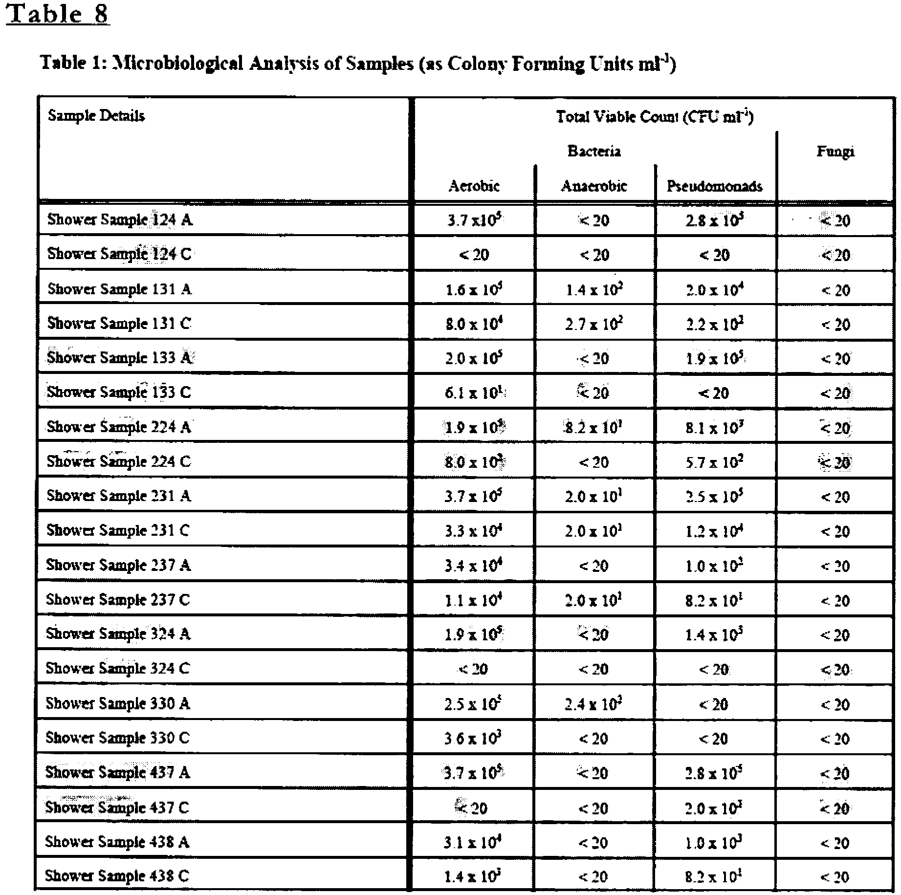
- The results below in Tables 9-12 represent analyses carried out using the poured plate technique for applying the samples to the plates. The TVCs were measured on the plates after 2 days for plates kept at 37°C and after 3 days for plates kept at 22°C.


- It can be seen from tables 8-12 that the 24 hour post treatment samples C taken in rooms 124, 133, 224, 324, 437, that were cleaned using the biocidal composition of the present invention in the applicator device of the present invention, show significantly reduced microbiological activity (low Total Viable Counts (TVCs). This is in contrast to the 24 hour post treatment samples C taken in rooms 131, 231, 237, 330, 438 that were cleaned using a conventional bleach composition, that show comparatively high microbiological activity (high TVCs).
- In addition, the Applicants have clearly shown that the known bleaching composition and sterilisation procedure, as recommended by HSE in their L8 Protocol, do not provide the same sterilisation effectiveness for sterilising shower apparatus as the present invention. In particular, the Applicants make the following observations in relation to the known bleaching composition and procedure:
- The bleach does not remove hardness scale that is present in the shower head and hose, to a greater or lesser extent depending on the water hardness levels in the local water supply. It is clear from the Applicant's tests that water hardness scale can have a significant impact on the 'key' for the development of a biofilm in the shower head and hose;
- The use of a bleach soaking technique is hazardous and time consuming to apply;
- It is questionable whether the required halogen residuals are established, the soaking time effectively monitored, frequencies of cleaning maintained and microbiological monitoring carried out, in any but the most carefully maintained systems;
- Under the current recommendations, even though the soaking sterilisation may be carried out very effectively, the systems will re-inoculate within 7-10 days of normal use, leaving a remaining period of approximately 12 weeks before these systems are recommended for a further bleach treatment under the guidelines;
- Whilst it is relatively easy to remove a flexible shower hose and head to allow the bleach soaking process to be carried out, it is almost impossible to apply this process to any fixed pipe system without significant professional intervention.
- The findings of the Applicant that the formation of a biofilm in the shower apparatus can be a key factor to the effectiveness of sterilisation of the shower apparatus supports the use of an acidic sequesterant in locations where there is hard water, in addition to the biocidal composition of the present invention.
Claims (15)
- A method of using a shower sterilisation system, said system comprising shower apparatus including water supply means (2) , a shower head (6) and shower conduit means (4) connecting the shower head (6) to the water supply means (2), said method including the steps of locating an applicator device (16) between the water supply means (2) and the shower head (6), locating a sterilisation or biocidal composition in the applicator device (16) and delivering said sterilisation or biocidal composition to one or more parts of said shower apparatus, characterised in that an acid sequestering composition is located in the applicator device (16) and delivered to the system before use of the biocidal or sterilisation composition.
- The method according to claim 1 wherein a biocidal active component in the biocidal or sterilisation composition is Bis-(3-aminopropyl)-dodecylamine.
- The method according to claim 2 wherein the sterilisation or biocidal composition is contained in a water soluble PVA sachet (54).
- The method according to claim 3 wherein the sterilisation or biocidal composition includes a non-aqueous carrier.
- The method according to claim 4 wherein the non-aqueous carrier is hexylene glycol.
- The method according to claim 1 wherein the sterilisation or biocidal composition includes one or more surface active bio-dispersants, a coloured dye and/or a fragrance.
- The method according to claim 1 wherein the sterilisation or biocidal composition includes 1-5% N-(3-aminopropyl)-N-dodecylpropae-1, 3, diamine, 2-10% Alkyl alkoxylate, 50-100% Alkylene glycol.
- The method according to claim 1 wherein the acid sequestering composition includes Hydroxyl Ethylidene Di Phosphonic acid (HEDP).
- The method according to claim 8 wherein the acid sequestering composition also includes a dispersion or wetting agent and a coloured dye.
- The method according to claim 1 wherein the acid sequestering composition is contained in a water soluble PVA sachet (54).
- The method according to claim 1 wherein the method includes the step of allowing water to flow through the shower apparatus to cause said sterilisation or biocidal composition to be delivered to one or more parts of the shower apparatus.
- The method according to claim 1 wherein the method includes the step of allow the sterilisation or biocidal composition to dissolve in the fluid flowing through the apparatus to form a chemical solution.
- The method according to claim 12 including the step of allowing the chemical solution to stand or rest for a pre-determined period of time within the apparatus to allow any active ingredients of the chemical solution to take effect.
- The method according to claim 13 wherein the pre-determined time period is between 5-60 minutes.
- The method according to claim 13 including the step of washing out the apparatus by allowing fluid to flow through the apparatus after a standing time period.
Applications Claiming Priority (2)
| Application Number | Priority Date | Filing Date | Title |
|---|---|---|---|
| GBGB1010808.2A GB201010808D0 (en) | 2010-06-28 | 2010-06-28 | Antimicrobial device for a shower |
| PCT/GB2011/051214 WO2012001400A1 (en) | 2010-06-28 | 2011-06-27 | Shower sterilisation system and method of use thereof |
Publications (2)
| Publication Number | Publication Date |
|---|---|
| EP2585643A1 EP2585643A1 (en) | 2013-05-01 |
| EP2585643B1 true EP2585643B1 (en) | 2018-03-21 |
Family
ID=42583071
Family Applications (1)
| Application Number | Title | Priority Date | Filing Date |
|---|---|---|---|
| EP11729664.0A Not-in-force EP2585643B1 (en) | 2010-06-28 | 2011-06-27 | Shower sterilisation system and method of use thereof |
Country Status (10)
| Country | Link |
|---|---|
| US (1) | US8894927B2 (en) |
| EP (1) | EP2585643B1 (en) |
| CN (1) | CN103080438B (en) |
| AU (1) | AU2011273135B2 (en) |
| BR (1) | BR112012033536A2 (en) |
| CA (1) | CA2803702C (en) |
| GB (1) | GB201010808D0 (en) |
| SG (1) | SG186806A1 (en) |
| WO (1) | WO2012001400A1 (en) |
| ZA (1) | ZA201209716B (en) |
Families Citing this family (20)
| Publication number | Priority date | Publication date | Assignee | Title |
|---|---|---|---|---|
| WO2015171730A1 (en) | 2014-05-06 | 2015-11-12 | Inceptus, Inc. | Devices, systems and methods for ozone sanitization of continuous positive airway pressure devices |
| US10434204B2 (en) | 2011-07-15 | 2019-10-08 | Soclean, Inc. | Technologies for sanitizing mist humidifiers |
| US9669124B2 (en) | 2011-07-15 | 2017-06-06 | Soclean, Inc. | Devices, systems and methods for treating multiple medical devices having passageways with ozone gas |
| US10427961B2 (en) | 2011-07-15 | 2019-10-01 | Soclean, Inc. | Technologies for sanitizing reservoirs |
| EP2731632B1 (en) | 2011-07-15 | 2017-08-30 | SoClean, Inc. | CPAP device with ozone generator |
| US9486817B2 (en) * | 2013-03-15 | 2016-11-08 | Delta Faucet Company | Ozone shower device |
| EP3350156B1 (en) | 2015-09-17 | 2022-12-28 | Ecolab USA Inc. | Methods of making triamine solids |
| EP3381284B1 (en) | 2015-09-17 | 2025-02-19 | Ecolab USA Inc. | Triamine solidification using diacids |
| US11104586B2 (en) | 2016-07-25 | 2021-08-31 | Guillaume Bertrand | Water recycling system and method |
| IL249680B (en) * | 2016-12-21 | 2018-05-31 | Zabari Lidor | Self-sealing shower head with disinfectant |
| EP3707230B1 (en) | 2017-11-07 | 2025-06-18 | Ecolab USA Inc. | Alkaline cleaning composition and methods for removing lipstick |
| JP7449857B2 (en) | 2017-12-07 | 2024-03-14 | エコラボ ユーエスエー インコーポレイティド | Compositions and methods for removing lipstick using branched polyamines |
| AU2020240101B2 (en) | 2019-03-19 | 2025-04-17 | Soclean, Inc. | Technologies for sanitizing medical devices |
| CN210207264U (en) * | 2019-04-03 | 2020-03-31 | 九牧厨卫股份有限公司 | Washing and protecting article carrier and shower |
| US11511304B2 (en) | 2019-06-07 | 2022-11-29 | Kohler Co. | Shower column assembly |
| CN112043188B (en) | 2019-06-07 | 2024-04-02 | 科勒公司 | Shower column assembly |
| GB2609626A (en) * | 2021-08-09 | 2023-02-15 | Challenor Liam | Salt shower device |
| KR102377792B1 (en) * | 2021-12-14 | 2022-03-23 | (주) 산호인터내셔널 | Capsule inserting typed shower |
| US12280170B2 (en) | 2022-09-16 | 2025-04-22 | Soclean, Inc. | Disinfection systems and methods |
| CA3267823A1 (en) | 2022-09-16 | 2024-03-21 | Soclean, Inc. | Disinfection systems and methods |
Citations (2)
| Publication number | Priority date | Publication date | Assignee | Title |
|---|---|---|---|---|
| WO2000069475A1 (en) * | 1999-05-19 | 2000-11-23 | Steris Corporation | Flow through chemical indicator for measurement of biocidal agents |
| WO2001076647A1 (en) * | 2000-04-07 | 2001-10-18 | Novapharm Research (Australia) Pty Ltd | Process and composition for cleaning medical instruments |
Family Cites Families (27)
| Publication number | Priority date | Publication date | Assignee | Title |
|---|---|---|---|---|
| US1668802A (en) * | 1925-04-13 | 1928-05-08 | Frank J Cantrell | Plumbing fixture |
| US3460562A (en) * | 1967-08-04 | 1969-08-12 | Morgan M Moulder | Dissolver container having flanges at both ends to protect threaded hose couplings |
| US3847354A (en) * | 1973-09-20 | 1974-11-12 | R Lemond | Shower head additive dispenser |
| CA1007607A (en) * | 1973-10-02 | 1977-03-29 | National Sanitation Services Ltd. | Chemical dispenser |
| FR2264583A1 (en) * | 1974-03-19 | 1975-10-17 | Aquitaine Languedoc Etudes Tec | Mixer for primary and secondary streams - for adding liquids, pastes, powder, sol. particles to main fluid stream |
| DE2510381A1 (en) * | 1975-03-10 | 1976-09-16 | Fritz K Strauss | Two way refilled container for shower heads - holds additives for water and has bypass for optional plain water flow |
| FR2620470A1 (en) * | 1987-09-14 | 1989-03-17 | Gruffy Georges | Device for treatment of sanitary water |
| US4964892A (en) * | 1988-12-22 | 1990-10-23 | Rohm And Haas Company | Synergistic microbicidal combinations containing 2-N-octyl-3-isothiazolone and certain commercial biocides |
| DE9016641U1 (en) * | 1989-12-20 | 1991-03-14 | Quint, Alfred, 5810 Witten | Device for treating a water flow in a pipe |
| BE1008419A6 (en) * | 1994-07-01 | 1996-05-07 | Dotraco Nv | DOSER AND PATTERN USED FOR THIS. |
| JPH1171210A (en) * | 1997-08-28 | 1999-03-16 | Sanai Sekiyu Kk | Industrial preservatives |
| JP2000051869A (en) * | 1998-08-07 | 2000-02-22 | Karufa Chemical Kk | Living water purifying apparatus |
| US20020070293A1 (en) * | 2000-12-07 | 2002-06-13 | Ti Shih Ti | Shower filtration skin care device |
| WO2002050378A1 (en) * | 2000-12-18 | 2002-06-27 | Osborne James Douglas Macgrego | Soluble solids dispenser |
| CN2495243Y (en) * | 2001-07-17 | 2002-06-19 | 深圳市精锐实业有限公司 | Ozone shower device |
| TW578537U (en) * | 2002-08-08 | 2004-03-01 | Sheng-Jeng Wang | Device for automatically releasing material into water |
| ITRM20020543A1 (en) * | 2002-10-29 | 2004-04-30 | Simone Fiorentino De | DEVICE TO MAKE FOAM EXIT FROM THE SHOWER HEAD, WITH |
| EP1518607A1 (en) * | 2003-09-23 | 2005-03-30 | Takayasu Okubo | Feed device for adding a chemical substance to tap water |
| BRPI0615746A2 (en) * | 2005-09-13 | 2017-06-20 | Taminco | composition, and method for inhibiting or preventing biological growth in a composition |
| US7905429B2 (en) * | 2005-10-18 | 2011-03-15 | Water Pik, Inc. | Dispensing system and method for shower arm |
| US8393350B2 (en) * | 2005-11-15 | 2013-03-12 | Vidacco International, LLC | Methods and apparatus for introducing additives into a fluid flow |
| CH698604B1 (en) * | 2005-11-29 | 2009-09-15 | Creaholic Sa | Wash. |
| US7611070B2 (en) * | 2006-02-28 | 2009-11-03 | Paoluccio John J | Aspirating scented oxygen enriched faucet and shower head |
| US20080063723A1 (en) * | 2006-09-08 | 2008-03-13 | Sungmee Choi | Isothiazolin-3-one-containing antimicrobial composition |
| US8028933B2 (en) * | 2006-11-27 | 2011-10-04 | Nils Friis | Shower additive dispenser |
| DE202007011127U1 (en) * | 2007-08-09 | 2007-10-18 | Kobylinski, Konstantin Von | Fill the filled capsule with the water outlet of a water tap with the purpose to mix the filling and the water in a fine consistency |
| ITMI20080200A1 (en) * | 2008-02-08 | 2009-08-09 | Enrico Sanvittore | HYDRO-MIXER DEVICE APPLICABLE TO WATER DISPENSERS, PARTICULARLY OF HYGIENIC AND SANITARY SYSTEMS, FOR THE ADDITIVATION OF WATER WITH HYDRO-SOLUBLE SUBSTANCES. |
-
2010
- 2010-06-28 GB GBGB1010808.2A patent/GB201010808D0/en not_active Ceased
-
2011
- 2011-06-27 WO PCT/GB2011/051214 patent/WO2012001400A1/en not_active Ceased
- 2011-06-27 AU AU2011273135A patent/AU2011273135B2/en not_active Ceased
- 2011-06-27 EP EP11729664.0A patent/EP2585643B1/en not_active Not-in-force
- 2011-06-27 CN CN201180041547.0A patent/CN103080438B/en not_active Expired - Fee Related
- 2011-06-27 SG SG2012094942A patent/SG186806A1/en unknown
- 2011-06-27 CA CA2803702A patent/CA2803702C/en not_active Expired - Fee Related
- 2011-06-27 BR BR112012033536A patent/BR112012033536A2/en not_active IP Right Cessation
-
2012
- 2012-12-21 ZA ZA2012/09716A patent/ZA201209716B/en unknown
- 2012-12-21 US US13/724,325 patent/US8894927B2/en not_active Expired - Fee Related
Patent Citations (2)
| Publication number | Priority date | Publication date | Assignee | Title |
|---|---|---|---|---|
| WO2000069475A1 (en) * | 1999-05-19 | 2000-11-23 | Steris Corporation | Flow through chemical indicator for measurement of biocidal agents |
| WO2001076647A1 (en) * | 2000-04-07 | 2001-10-18 | Novapharm Research (Australia) Pty Ltd | Process and composition for cleaning medical instruments |
Also Published As
| Publication number | Publication date |
|---|---|
| US20130177475A1 (en) | 2013-07-11 |
| CA2803702A1 (en) | 2012-01-05 |
| AU2011273135A1 (en) | 2013-01-31 |
| BR112012033536A2 (en) | 2016-11-29 |
| EP2585643A1 (en) | 2013-05-01 |
| AU2011273135B2 (en) | 2014-10-23 |
| WO2012001400A1 (en) | 2012-01-05 |
| CN103080438A (en) | 2013-05-01 |
| WO2012001400A4 (en) | 2012-03-01 |
| GB201010808D0 (en) | 2010-08-11 |
| CN103080438B (en) | 2016-01-13 |
| ZA201209716B (en) | 2013-08-28 |
| US8894927B2 (en) | 2014-11-25 |
| CA2803702C (en) | 2015-06-23 |
| SG186806A1 (en) | 2013-02-28 |
Similar Documents
| Publication | Publication Date | Title |
|---|---|---|
| US8894927B2 (en) | Shower sterilisation system and method of use thereof | |
| US6528467B1 (en) | Slime remover and slime preventing/removing agent | |
| CA2792028C (en) | Molybdate-free sterilization composition containing peracetic acid | |
| JP3578655B2 (en) | Slime remover for drain | |
| ES2775398T3 (en) | Process to decontaminate or sterilize an article with a composition containing peroxide and an antimicrobial agent | |
| WO2007125100A1 (en) | Method and device for disinfecting a space | |
| JP2006502836A (en) | Controlled dose delivery to pressurized water systems of chlorine dioxide or other disinfectants | |
| DE69523932T2 (en) | CONTAINER WITH INTERNAL LIQUID DISTRIBUTION OPEN FOR RECEIVING A DEVICE WITH INTERNAL DUCTURES DURING STERILIZATION | |
| JP4603795B2 (en) | Method of sterilizing and cleaning a water supply system, in particular a water supply system in swimming and bathing pool facilities, and apparatus for carrying out the same | |
| AU2011308621A1 (en) | Device for disinfecting and/or rinsing endoscopes with limited escape of fumes | |
| US6403032B1 (en) | Assembly for dispensing sanitary agents into drains | |
| US10785998B2 (en) | Method of using a cleaning, disinfecting and lubricating composition for a dental unit or beer fluid encompassing system | |
| DE102007060476A1 (en) | Antibacterial method for drawing off/tapping a drinking liquid at drain cocks on bar installations, on tap heads or at points for delivering liquids sprays a drain area on a tap head intermittently with a disinfecting cleaning solution | |
| US20190134682A1 (en) | Methods comprising to clean and/or lubricate fluid encompassing systems | |
| JPS62215507A (en) | Prevention of putrefaction of liquid such as water-soluble working oil, water or the like | |
| JP4959179B2 (en) | Deodorizing and antifouling cleaning method for circulation cleaning type men's toilet and circulation cleaning type men's toilet used in the method | |
| CN210301790U (en) | Degassing unit of pulmonary function appearance | |
| WO2026035849A1 (en) | Solid chemistry dispensing system and method of use | |
| JP2001252674A (en) | Functional water generator | |
| Gruninger | Disease transmission through dental unit water: an update | |
| JP2003082735A (en) | Household bacteria shut-off sink drain trap | |
| Itami et al. | Decontamination effect of neutral electrolysed water for spray nozzles of electric warm-water bidet toilet seats in the healthcare setting | |
| HK1038384A (en) | Slime remover and slime preventing/removing agent | |
| JP2021014980A (en) | Chemical substance rod for hvac fluid conditioning system and manufacturing method | |
| US20030066801A1 (en) | Dental unit water system treatment |
Legal Events
| Date | Code | Title | Description |
|---|---|---|---|
| PUAI | Public reference made under article 153(3) epc to a published international application that has entered the european phase |
Free format text: ORIGINAL CODE: 0009012 |
|
| 17P | Request for examination filed |
Effective date: 20130107 |
|
| AK | Designated contracting states |
Kind code of ref document: A1 Designated state(s): AL AT BE BG CH CY CZ DE DK EE ES FI FR GB GR HR HU IE IS IT LI LT LU LV MC MK MT NL NO PL PT RO RS SE SI SK SM TR |
|
| DAX | Request for extension of the european patent (deleted) | ||
| RAP1 | Party data changed (applicant data changed or rights of an application transferred) |
Owner name: OMNIA-KLENZ LTD. |
|
| RIN1 | Information on inventor provided before grant (corrected) |
Inventor name: FINCH, STEPHEN |
|
| 17Q | First examination report despatched |
Effective date: 20150504 |
|
| GRAP | Despatch of communication of intention to grant a patent |
Free format text: ORIGINAL CODE: EPIDOSNIGR1 |
|
| INTG | Intention to grant announced |
Effective date: 20171011 |
|
| GRAS | Grant fee paid |
Free format text: ORIGINAL CODE: EPIDOSNIGR3 |
|
| GRAA | (expected) grant |
Free format text: ORIGINAL CODE: 0009210 |
|
| AK | Designated contracting states |
Kind code of ref document: B1 Designated state(s): AL AT BE BG CH CY CZ DE DK EE ES FI FR GB GR HR HU IE IS IT LI LT LU LV MC MK MT NL NO PL PT RO RS SE SI SK SM TR |
|
| REG | Reference to a national code |
Ref country code: GB Ref legal event code: FG4D |
|
| REG | Reference to a national code |
Ref country code: CH Ref legal event code: EP |
|
| REG | Reference to a national code |
Ref country code: AT Ref legal event code: REF Ref document number: 981252 Country of ref document: AT Kind code of ref document: T Effective date: 20180415 |
|
| REG | Reference to a national code |
Ref country code: IE Ref legal event code: FG4D |
|
| REG | Reference to a national code |
Ref country code: DE Ref legal event code: R096 Ref document number: 602011046679 Country of ref document: DE |
|
| REG | Reference to a national code |
Ref country code: FR Ref legal event code: PLFP Year of fee payment: 8 |
|
| REG | Reference to a national code |
Ref country code: NL Ref legal event code: MP Effective date: 20180321 |
|
| PG25 | Lapsed in a contracting state [announced via postgrant information from national office to epo] |
Ref country code: NO Free format text: LAPSE BECAUSE OF FAILURE TO SUBMIT A TRANSLATION OF THE DESCRIPTION OR TO PAY THE FEE WITHIN THE PRESCRIBED TIME-LIMIT Effective date: 20180621 Ref country code: FI Free format text: LAPSE BECAUSE OF FAILURE TO SUBMIT A TRANSLATION OF THE DESCRIPTION OR TO PAY THE FEE WITHIN THE PRESCRIBED TIME-LIMIT Effective date: 20180321 Ref country code: HR Free format text: LAPSE BECAUSE OF FAILURE TO SUBMIT A TRANSLATION OF THE DESCRIPTION OR TO PAY THE FEE WITHIN THE PRESCRIBED TIME-LIMIT Effective date: 20180321 Ref country code: LT Free format text: LAPSE BECAUSE OF FAILURE TO SUBMIT A TRANSLATION OF THE DESCRIPTION OR TO PAY THE FEE WITHIN THE PRESCRIBED TIME-LIMIT Effective date: 20180321 Ref country code: CY Free format text: LAPSE BECAUSE OF FAILURE TO SUBMIT A TRANSLATION OF THE DESCRIPTION OR TO PAY THE FEE WITHIN THE PRESCRIBED TIME-LIMIT Effective date: 20180321 |
|
| REG | Reference to a national code |
Ref country code: LT Ref legal event code: MG4D |
|
| REG | Reference to a national code |
Ref country code: AT Ref legal event code: MK05 Ref document number: 981252 Country of ref document: AT Kind code of ref document: T Effective date: 20180321 |
|
| PG25 | Lapsed in a contracting state [announced via postgrant information from national office to epo] |
Ref country code: BG Free format text: LAPSE BECAUSE OF FAILURE TO SUBMIT A TRANSLATION OF THE DESCRIPTION OR TO PAY THE FEE WITHIN THE PRESCRIBED TIME-LIMIT Effective date: 20180621 Ref country code: GR Free format text: LAPSE BECAUSE OF FAILURE TO SUBMIT A TRANSLATION OF THE DESCRIPTION OR TO PAY THE FEE WITHIN THE PRESCRIBED TIME-LIMIT Effective date: 20180622 Ref country code: SE Free format text: LAPSE BECAUSE OF FAILURE TO SUBMIT A TRANSLATION OF THE DESCRIPTION OR TO PAY THE FEE WITHIN THE PRESCRIBED TIME-LIMIT Effective date: 20180321 Ref country code: LV Free format text: LAPSE BECAUSE OF FAILURE TO SUBMIT A TRANSLATION OF THE DESCRIPTION OR TO PAY THE FEE WITHIN THE PRESCRIBED TIME-LIMIT Effective date: 20180321 Ref country code: RS Free format text: LAPSE BECAUSE OF FAILURE TO SUBMIT A TRANSLATION OF THE DESCRIPTION OR TO PAY THE FEE WITHIN THE PRESCRIBED TIME-LIMIT Effective date: 20180321 |
|
| PG25 | Lapsed in a contracting state [announced via postgrant information from national office to epo] |
Ref country code: EE Free format text: LAPSE BECAUSE OF FAILURE TO SUBMIT A TRANSLATION OF THE DESCRIPTION OR TO PAY THE FEE WITHIN THE PRESCRIBED TIME-LIMIT Effective date: 20180321 Ref country code: IT Free format text: LAPSE BECAUSE OF FAILURE TO SUBMIT A TRANSLATION OF THE DESCRIPTION OR TO PAY THE FEE WITHIN THE PRESCRIBED TIME-LIMIT Effective date: 20180321 Ref country code: ES Free format text: LAPSE BECAUSE OF FAILURE TO SUBMIT A TRANSLATION OF THE DESCRIPTION OR TO PAY THE FEE WITHIN THE PRESCRIBED TIME-LIMIT Effective date: 20180321 Ref country code: AL Free format text: LAPSE BECAUSE OF FAILURE TO SUBMIT A TRANSLATION OF THE DESCRIPTION OR TO PAY THE FEE WITHIN THE PRESCRIBED TIME-LIMIT Effective date: 20180321 Ref country code: RO Free format text: LAPSE BECAUSE OF FAILURE TO SUBMIT A TRANSLATION OF THE DESCRIPTION OR TO PAY THE FEE WITHIN THE PRESCRIBED TIME-LIMIT Effective date: 20180321 Ref country code: NL Free format text: LAPSE BECAUSE OF FAILURE TO SUBMIT A TRANSLATION OF THE DESCRIPTION OR TO PAY THE FEE WITHIN THE PRESCRIBED TIME-LIMIT Effective date: 20180321 Ref country code: PL Free format text: LAPSE BECAUSE OF FAILURE TO SUBMIT A TRANSLATION OF THE DESCRIPTION OR TO PAY THE FEE WITHIN THE PRESCRIBED TIME-LIMIT Effective date: 20180321 |
|
| PG25 | Lapsed in a contracting state [announced via postgrant information from national office to epo] |
Ref country code: CZ Free format text: LAPSE BECAUSE OF FAILURE TO SUBMIT A TRANSLATION OF THE DESCRIPTION OR TO PAY THE FEE WITHIN THE PRESCRIBED TIME-LIMIT Effective date: 20180321 Ref country code: SK Free format text: LAPSE BECAUSE OF FAILURE TO SUBMIT A TRANSLATION OF THE DESCRIPTION OR TO PAY THE FEE WITHIN THE PRESCRIBED TIME-LIMIT Effective date: 20180321 Ref country code: AT Free format text: LAPSE BECAUSE OF FAILURE TO SUBMIT A TRANSLATION OF THE DESCRIPTION OR TO PAY THE FEE WITHIN THE PRESCRIBED TIME-LIMIT Effective date: 20180321 Ref country code: SM Free format text: LAPSE BECAUSE OF FAILURE TO SUBMIT A TRANSLATION OF THE DESCRIPTION OR TO PAY THE FEE WITHIN THE PRESCRIBED TIME-LIMIT Effective date: 20180321 |
|
| PG25 | Lapsed in a contracting state [announced via postgrant information from national office to epo] |
Ref country code: PT Free format text: LAPSE BECAUSE OF FAILURE TO SUBMIT A TRANSLATION OF THE DESCRIPTION OR TO PAY THE FEE WITHIN THE PRESCRIBED TIME-LIMIT Effective date: 20180723 |
|
| REG | Reference to a national code |
Ref country code: DE Ref legal event code: R097 Ref document number: 602011046679 Country of ref document: DE |
|
| PLBE | No opposition filed within time limit |
Free format text: ORIGINAL CODE: 0009261 |
|
| STAA | Information on the status of an ep patent application or granted ep patent |
Free format text: STATUS: NO OPPOSITION FILED WITHIN TIME LIMIT |
|
| PG25 | Lapsed in a contracting state [announced via postgrant information from national office to epo] |
Ref country code: DK Free format text: LAPSE BECAUSE OF FAILURE TO SUBMIT A TRANSLATION OF THE DESCRIPTION OR TO PAY THE FEE WITHIN THE PRESCRIBED TIME-LIMIT Effective date: 20180321 |
|
| REG | Reference to a national code |
Ref country code: CH Ref legal event code: PL |
|
| 26N | No opposition filed |
Effective date: 20190102 |
|
| REG | Reference to a national code |
Ref country code: BE Ref legal event code: MM Effective date: 20180630 |
|
| PG25 | Lapsed in a contracting state [announced via postgrant information from national office to epo] |
Ref country code: LU Free format text: LAPSE BECAUSE OF NON-PAYMENT OF DUE FEES Effective date: 20180627 Ref country code: MC Free format text: LAPSE BECAUSE OF FAILURE TO SUBMIT A TRANSLATION OF THE DESCRIPTION OR TO PAY THE FEE WITHIN THE PRESCRIBED TIME-LIMIT Effective date: 20180321 |
|
| REG | Reference to a national code |
Ref country code: IE Ref legal event code: MM4A |
|
| PG25 | Lapsed in a contracting state [announced via postgrant information from national office to epo] |
Ref country code: CH Free format text: LAPSE BECAUSE OF NON-PAYMENT OF DUE FEES Effective date: 20180630 Ref country code: LI Free format text: LAPSE BECAUSE OF NON-PAYMENT OF DUE FEES Effective date: 20180630 Ref country code: IE Free format text: LAPSE BECAUSE OF NON-PAYMENT OF DUE FEES Effective date: 20180627 |
|
| PG25 | Lapsed in a contracting state [announced via postgrant information from national office to epo] |
Ref country code: SI Free format text: LAPSE BECAUSE OF FAILURE TO SUBMIT A TRANSLATION OF THE DESCRIPTION OR TO PAY THE FEE WITHIN THE PRESCRIBED TIME-LIMIT Effective date: 20180321 Ref country code: BE Free format text: LAPSE BECAUSE OF NON-PAYMENT OF DUE FEES Effective date: 20180630 |
|
| PG25 | Lapsed in a contracting state [announced via postgrant information from national office to epo] |
Ref country code: MT Free format text: LAPSE BECAUSE OF NON-PAYMENT OF DUE FEES Effective date: 20180627 |
|
| PG25 | Lapsed in a contracting state [announced via postgrant information from national office to epo] |
Ref country code: TR Free format text: LAPSE BECAUSE OF FAILURE TO SUBMIT A TRANSLATION OF THE DESCRIPTION OR TO PAY THE FEE WITHIN THE PRESCRIBED TIME-LIMIT Effective date: 20180321 |
|
| PG25 | Lapsed in a contracting state [announced via postgrant information from national office to epo] |
Ref country code: HU Free format text: LAPSE BECAUSE OF FAILURE TO SUBMIT A TRANSLATION OF THE DESCRIPTION OR TO PAY THE FEE WITHIN THE PRESCRIBED TIME-LIMIT; INVALID AB INITIO Effective date: 20110627 |
|
| PG25 | Lapsed in a contracting state [announced via postgrant information from national office to epo] |
Ref country code: MK Free format text: LAPSE BECAUSE OF NON-PAYMENT OF DUE FEES Effective date: 20180321 |
|
| PG25 | Lapsed in a contracting state [announced via postgrant information from national office to epo] |
Ref country code: IS Free format text: LAPSE BECAUSE OF FAILURE TO SUBMIT A TRANSLATION OF THE DESCRIPTION OR TO PAY THE FEE WITHIN THE PRESCRIBED TIME-LIMIT Effective date: 20180721 |
|
| PGFP | Annual fee paid to national office [announced via postgrant information from national office to epo] |
Ref country code: FR Payment date: 20200624 Year of fee payment: 10 |
|
| PGFP | Annual fee paid to national office [announced via postgrant information from national office to epo] |
Ref country code: DE Payment date: 20200626 Year of fee payment: 10 |
|
| REG | Reference to a national code |
Ref country code: DE Ref legal event code: R119 Ref document number: 602011046679 Country of ref document: DE |
|
| PG25 | Lapsed in a contracting state [announced via postgrant information from national office to epo] |
Ref country code: DE Free format text: LAPSE BECAUSE OF NON-PAYMENT OF DUE FEES Effective date: 20220101 |
|
| PG25 | Lapsed in a contracting state [announced via postgrant information from national office to epo] |
Ref country code: FR Free format text: LAPSE BECAUSE OF NON-PAYMENT OF DUE FEES Effective date: 20210630 |
|
| PGFP | Annual fee paid to national office [announced via postgrant information from national office to epo] |
Ref country code: GB Payment date: 20230613 Year of fee payment: 13 |
|
| GBPC | Gb: european patent ceased through non-payment of renewal fee |
Effective date: 20240627 |
|
| PG25 | Lapsed in a contracting state [announced via postgrant information from national office to epo] |
Ref country code: GB Free format text: LAPSE BECAUSE OF NON-PAYMENT OF DUE FEES Effective date: 20240627 |