EP2585232B1 - Vertrocknungsschutzgerät und verfahren - Google Patents
Vertrocknungsschutzgerät und verfahren Download PDFInfo
- Publication number
- EP2585232B1 EP2585232B1 EP11749902.0A EP11749902A EP2585232B1 EP 2585232 B1 EP2585232 B1 EP 2585232B1 EP 11749902 A EP11749902 A EP 11749902A EP 2585232 B1 EP2585232 B1 EP 2585232B1
- Authority
- EP
- European Patent Office
- Prior art keywords
- container
- drying device
- delivery
- fluid
- liquid
- Prior art date
- Legal status (The legal status is an assumption and is not a legal conclusion. Google has not performed a legal analysis and makes no representation as to the accuracy of the status listed.)
- Active
Links
Images



Classifications
-
- B—PERFORMING OPERATIONS; TRANSPORTING
- B05—SPRAYING OR ATOMISING IN GENERAL; APPLYING FLUENT MATERIALS TO SURFACES, IN GENERAL
- B05C—APPARATUS FOR APPLYING FLUENT MATERIALS TO SURFACES, IN GENERAL
- B05C11/00—Component parts, details or accessories not specifically provided for in groups B05C1/00 - B05C9/00
- B05C11/11—Vats or other containers for liquids or other fluent materials
-
- B—PERFORMING OPERATIONS; TRANSPORTING
- B65—CONVEYING; PACKING; STORING; HANDLING THIN OR FILAMENTARY MATERIAL
- B65B—MACHINES, APPARATUS OR DEVICES FOR, OR METHODS OF, PACKAGING ARTICLES OR MATERIALS; UNPACKING
- B65B31/00—Packaging articles or materials under special atmospheric or gaseous conditions; Adding propellants to aerosol containers
- B65B31/04—Evacuating, pressurising or gasifying filled containers or wrappers by means of nozzles through which air or other gas, e.g. an inert gas, is withdrawn or supplied
-
- B—PERFORMING OPERATIONS; TRANSPORTING
- B05—SPRAYING OR ATOMISING IN GENERAL; APPLYING FLUENT MATERIALS TO SURFACES, IN GENERAL
- B05B—SPRAYING APPARATUS; ATOMISING APPARATUS; NOZZLES
- B05B15/00—Details of spraying plant or spraying apparatus not otherwise provided for; Accessories
- B05B15/50—Arrangements for cleaning; Arrangements for preventing deposits, drying-out or blockage; Arrangements for detecting improper discharge caused by the presence of foreign matter
-
- B—PERFORMING OPERATIONS; TRANSPORTING
- B05—SPRAYING OR ATOMISING IN GENERAL; APPLYING FLUENT MATERIALS TO SURFACES, IN GENERAL
- B05C—APPARATUS FOR APPLYING FLUENT MATERIALS TO SURFACES, IN GENERAL
- B05C21/00—Accessories or implements for use in connection with applying liquids or other fluent materials to surfaces, not provided for in groups B05C1/00 - B05C19/00
-
- B—PERFORMING OPERATIONS; TRANSPORTING
- B08—CLEANING
- B08B—CLEANING IN GENERAL; PREVENTION OF FOULING IN GENERAL
- B08B15/00—Preventing escape of dirt or fumes from the area where they are produced; Collecting or removing dirt or fumes from that area
- B08B15/02—Preventing escape of dirt or fumes from the area where they are produced; Collecting or removing dirt or fumes from that area using chambers or hoods covering the area
-
- B—PERFORMING OPERATIONS; TRANSPORTING
- B08—CLEANING
- B08B—CLEANING IN GENERAL; PREVENTION OF FOULING IN GENERAL
- B08B17/00—Methods preventing fouling
-
- B—PERFORMING OPERATIONS; TRANSPORTING
- B65—CONVEYING; PACKING; STORING; HANDLING THIN OR FILAMENTARY MATERIAL
- B65D—CONTAINERS FOR STORAGE OR TRANSPORT OF ARTICLES OR MATERIALS, e.g. BAGS, BARRELS, BOTTLES, BOXES, CANS, CARTONS, CRATES, DRUMS, JARS, TANKS, HOPPERS, FORWARDING CONTAINERS; ACCESSORIES, CLOSURES, OR FITTINGS THEREFOR; PACKAGING ELEMENTS; PACKAGES
- B65D43/00—Lids or covers for rigid or semi-rigid containers
Definitions
- the present invention concerns an anti-drying device to prevent the drying of fluid and semi-fluid products, pastes, gels, creams such as for example coloring products, pigments or paints, residues on delivery needles of a machine or device at least for the delivery and possibly for the automatic preparation, mixing and distribution of fluid coloring products, for example coloring liquids, paint bases, varnishes, enamels, inks or other fluid coloring substances.
- fluid coloring products for example coloring liquids, paint bases, varnishes, enamels, inks or other fluid coloring substances.
- Devices or machines to dispense or deliver fluid and semi-fluid products, pastes, gels, creams such as coloring products, pigments or paints are known, and are able to introduce a measured quantity of a product into a receptacle, containing, for example, a paint base to obtain the coloring product desired.
- Such devices or delivery machines normally comprise a delivery unit, or dispensing head, by means of which a desired quantity of one or more fluid products is delivered into a receptacle, normally containing a paint base.
- the delivery unit is typically mobile between an idle position and an operating position in which it cooperates with the container and traditionally comprises a plurality of delivery needles by means of which the lid of the container containing the paint base is perforated, and the fluid product is delivered inside it.
- a known delivery unit is described in the European patent application EP-A-2.040.830 in the name of the Applicant.
- the residual fluid product on the tip of the delivery needles, in contact with the air, tends to dry, usually in the period of time between one delivery step and the next, with negative effects on the performance of the delivery device or machine.
- a conditioning device described in the European patent EP-B-1.494.959 or an anti-drying device described in the aforementioned European patent EP-2.040.830 .
- Document US-A-2008/210774 describes an anti-drying device in accordance with the preamble of claim 1 to dampen the delivery nozzles of colorants which comprises a housing which defines a first chamber to house a reserve tank for the water and an open tray to hold a certain volume of water and in which a heating element is provided to vaporize the water. The vapor passes into a second open chamber of the tray, where the nozzles, when they are idle, are exposed to the vapor.
- Purpose of the present invention is to achieve an anti-drying device which has even greater performance and efficiency than known anti-drying devices, which is economical, rapid, functional, without negatively influencing the functioning of other components of the associated dispensing machine.
- the present invention is an anti-drying device in accordance with claim 1, while the dependent claims describe other characteristics of the invention or variants to the main inventive idea.
- an anti-drying device can be used to humidify the delivery means of fluid and semi-fluid products, pastes, gels, creams such as for example coloring products, pigments or paints, of a machine at least for the delivery and possibly for the automatic preparation, mixing and distribution of at least a fluid product into a closed receptacle, for example for the delivery of a fluid coloring product into a receptacle which contains a paint base.
- the anti-drying device of the present invention comprises a container or receptacle hermetically closed by means of a closing lid and which has an inner volume inside which there is a fluid, liquid and/or vapor, suitable to humidify possible residues of fluid product on the delivery means.
- the closing lid is configured both to confine the liquid and/or the vapor inside the container and also to introduce and house, through at least one of its portions, at least the ends of the delivery means inside the closed container, so that they are in contact with the liquid and/or vapor so as to prevent the drying thereof.
- the delivery machine of the fluid product When the delivery machine of the fluid product is idle, it will be possible to insert the delivery means into the container in which the liquid and/or vapor is present, preventing the drying of possible residues of fluid product present thereon.
- the delivery means for example the tips of the needles which deliver the coloring substances, are prevented from drying during periods of idleness.
- the vaporization times are more rapid and, if necessary, there will be less heat energy needed.
- the vapor generated by heating, or in a natural way by exploiting the vapor tension of the liquid at ambient temperature remains confined in the container, and this, as well as eliminating the creation of undesired humidity on the components of the dispensing machine and outside it, makes the integration of liquid unnecessary.
- the container is provided with a closing lid which has a portion made, at least partly, with a membrane of an elastic material able to dilate, when the delivery means are inserted through it in order to be kept damp, during the performance of the anti-drying action, and to re-compact, when the delivery means are removed from the container, thus preventing the fluid and vapor contained therein from leaking out.
- the use of the membrane which acts as a closing element is advantageous because it allows an optimal control of the humidity inside the container.
- the presence of the membrane on the container has the advantage that, when the delivery means are removed through it, there is an effect of scraping the residues of fluid product possibly present, contributing to increase the cleanliness of the delivery means, obtaining a considerable improvement in the delivery.
- the anti-drying device of the present invention comprises a mechanical arm, pivoted on a vertical pin which bears a support plate of the fluid container at one end, the mechanical arm being rotatable between a first operating position in which the container is in cooperation with the delivery means for the anti-drying action, and a second operating position, rotated with respect to the first, where it is disengaged.
- the present invention also concerns a method to humidify delivery means in accordance with claim 12 for fluid and semi-fluid products, pastes, gels, creams such as for example coloring products, pigments or paints, of a machine at least for the automatic delivery of at least a fluid product into a closed container.
- the method comprises a step of introducing into a container or receptacle, hermetically closed by means of a closing lid and which has an internal volume in which there is a fluid, liquid and/or vapor, at least the ends of the delivery means through a portion of the closing lid, confining the liquid and/or vapor inside the container so that at least the ends of the delivery means are in contact with the liquid and/or vapor, so as to prevent them from drying out.
- an anti-drying device 10 can be used to prevent the drying of residues of fluid products in delivery needles 74 of a delivery device 21 of a machine 75 to automatically deliver fluid coloring products in closed receptacles 11.
- the anti-drying device 10 comprises a container or receptacle 79, hermetically closed by means of a closing lid 82 and substantially similar to the recipients 11, inside which a fluid or liquid is present, such as water and/or aqueous vapor, and a support plate 78 on which the container 79 is disposed, comprising heating means 81, in this case an electric resistance integrated into it, by means of which to heat-regulate the support plate 78 in order to generate and maintain a desired quantity of liquid and vapor inside the container 79.
- the heating means 81 can be set to a desired temperature, to obtain the desired balance between liquid and vapor inside the container 79.
- the closing lid 82 is configured both to confine the liquid and/or vapor inside the container 79 and also to allow the introduction, through at least one of its portions, of the delivery needles 74 of the delivery device 21 inside the closed container 79 so that they are in contact with the liquid and/or vapor, so as to prevent them from drying out.
- the same closed container 79 which contains the liquid by means of which the anti-drying vapor is generated also comprises the heating means 81, achieving a more compact device.
- the container 79 since the container 79 is hermetically closed by the closing lid 82, the liquid which generates the vapor is not wasted, but remains confined inside the volume of the container 79, without needing topping up or integrations and also without dispersing inside or outside the machine 75. Moreover, as the container 79 is closed, even the heat energy required for evaporation will be less, with obvious saving in terms of time and costs.
- the container 79 is attached in a selectively removable way to the support plate 78.
- the container 79 is provided with releasable attachment means 72 ( fig. 6 ), of the bayonet type for example, able to cooperate with mating counter attachment means provided on the support plate 78, for an easy attachment to the support plate 78.
- the container 79 can be easily removed from the support plate 78 to guarantee easy access and cleaning by the specialized operator, seeing that, normally, after a certain number of hours of functioning, the liquid contained will have to be removed and substituted.
- the cleaning operation will be indicated by the operating system which manages the functioning of the device 10 by means of a suitable message.
- the sizes of the container 79 which can, for example, be a cylindrical shaped can, are configured to house inside it at least the part or end of the needles 74 on which, normally, there can be residue of fluid product which is delivered.
- a liquid for example water
- the closing lid 82 with which the container 79 is provided has a portion made, at least partly, with a membrane 83 of an elastic material able to dilate, when the delivery needles 74 are inserted through it in order to be kept damp, during the performance of the anti-drying action, and to re-compact, when the needles 74 are removed, preventing the liquid contained therein from leaking out.
- the membrane portion 83 of the closing lid 82 of the container 79 is sized in a manner coordinated with the overall plane bulk of the plurality of needles 74, so as to guarantee that each of them is inserted inside the container 79 for the anti-drying action.
- the anti-drying device is shown used in a machine 75 for the automatic preparation and distribution of fluid coloring products, contained in closed receptacles 11, which in this case comprises a support structure 12, divided into substantially three modular compartments 13, 14 and 15, integrated with each other, as described in the copending patent application in Italy of the Applicant n. UD2010A000126 with the same priority date and entitled "MACHINE FOR THE AUTOMATIC PREPARATION AND DISTRIBUTION OF FLUID COLORING PRODUCTS CONTAINED IN CLOSED RECEPTACLES".
- the receptacles 11 can be either metal, such as steel, or plastic material and can be a cylindrical shape or any other shape, such as for example a parallelepiped, with a square or rectangular base. Each of them can contain a fluid paint base, which can be for example transparent or white, to which a colorant is then added, substantially consisting of pigments.
- Each receptacle 11 can be closed by a lid provided at the center with a membrane, of a known type, which has the characteristic of being holed by one or more needles and closing automatically when each needle is removed, as is the case of the membrane 83 of the container 79.
- a plurality of tanks 20 are disposed ( fig. 1 ), which can be of any known type, for example as described in the European patent EP-B-1.744.826 , in the name of the present Applicant, in each of which a different coloring substance is contained.
- a delivery device 21 is disposed, which can be of any known type, for example as described in the Italian patent IT-B-1.370.076 , in the name of the present Applicant.
- the delivery device 21 is connected to the tanks 20 by means of pipes 23 ( figs. 4 and 5 ) of any known type.
- a mixing device 22 is disposed in this case, which can be of any known type, for example of the type described in the European patent EP-B-1.417.024 granted on 21.09.2005 to the Applicant.
- a loading station 25 ( figs. 1 and 3 ) is disposed, which comprises a plate 26, of a circular shape for example, which acts as a support element and centering member for one receptacle 11 at a time.
- the loading station 25 has a first vertical axis Z1 ( figs. 3 - 5 ).
- an access door 29 is disposed, of a semi-circular shape and comprising, in some forms of embodiment, two panels 29a and 29b, each of which has an angular development of 90° to act as a rotating bushing.
- transfer means 30 ( figs. 1 , 3 , 4 and 5 ) are able to selectively and automatically transfer the receptacle 11, together with the plate 26, both from the loading station 25 to the delivery device 21, along a first horizontal axis X, and from the delivery device 21 to the mixing device 22, along a second horizontal axis Y, perpendicular to the axis X, and vice versa, to return them to the loading station 25.
- data input means 50 are disposed, connected to a central control unit 59 ( fig. 1 ) and able to be actuated by the user in order to choose the sizes and the capacity of the receptacle 11, the type of paint base and/or the color of the fluid coloring product to be obtained.
- the delivery device 21 ( figs. 4 and 5 ) comprises a plate 73 on which the needles 74 are mounted, disposed parallel and concentric to the vertical axis Z2 and each connected to a corresponding pipe 23.
- the plate 73 is mobile vertically along the vertical axis Z2 by means of an electric motor, of a known type and not shown in the drawings, which is also controlled by the central control unit 59.
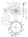
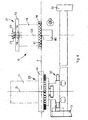
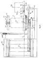
- the anti-drying device 10 ( figs. 3-6 ) used in the machine 75 comprises a mechanical arm 76, pivoted on a vertical pin 77 which bears the support plate 78 at one end, which can be heat-regulated with the electric resistance 81 integrated in it, on which the container 79 is removably disposed.
- the mechanical arm 76 is rotatable by means of an electric motor 80, controlled by the central control unit 59, between a first operating position in which it is aligned with the horizontal axis Y ( figs. 3 and 4 ) and a second operating position, rotated by 90° with respect to the first, that is, parallel to the horizontal axis X ( figs. 5 and 6 and shown by dashes in fig. 3 ).
- the container 79 In the first operating condition ( figs. 3 and 4 ) the container 79 is coaxial to the second vertical axis Z2 and the plate 73 is lowered against the container 79 ( fig. 4 ), so that the tips of the needles 74 are inside the latter, remaining damp thanks to the liquid and/or vapor contained therein. In the second operating position ( figs. 3 , 5 and 6 ) the container 79 is coaxial to a fourth vertical axis Z4, outside the bulk of the plate 26 and of the plate 73.
- the method with which the anti-drying device 10 as described heretofore is used functions in the machine 75 as follows.
- the user by means of the data input means 50, chooses and selects the characteristics of the specific fluid product that he intends to purchase.
- the user takes the type of receptacle 11 from a store or shelf which contains the type of paint base for example and which has the capacity he has chosen, and positions it in the loading station 25 ( fig. 1 ), centering it on the plate 26.
- the access door 29 ( figs. 2 and 3 ) is closed so that the two panels 29a and 29b are disposed in front of the receptacle 11 (position shown by dashes in figs. 2 and 3 ) and therefore so that nobody can access the loading station 25, until the end of the operating cycle.
- the central control unit 59 can automatically carry out a step to verify that the receptacle 11 is the type chosen by the user, and also that it is centered on the plate 26, possibly inviting the user to correct the positioning or substitute the receptacle 11.
- the central control unit 59 sets and activates the functioning of the heating means 81, in order to have the desired atmosphere saturated with vapor inside the container 79. Normally, at the beginning, the needles 74 of the delivery device 21 are inserted in the container 79, to prevent drying.
- the central control unit 59 automatically carries out a step of preparing the delivery device 21, lifting first the plate 73 ( fig. 5 ) and then rotating the mechanical arm 76 by 90° in a clockwise direction ( fig. 3 ), by means of the electric motor 80, to bring it together with the container 10 into the second operating position, aligned with the vertical axis Z4.
- a positioning step is then carried out, under the control of the central control unit 59, by means of the transfer means 30, to position the receptacle 11 aligned to the vertical axis Z2, instead of the container 79, and to deliver coloring substances inside the receptacle 11.
- the plate 73 of the delivery device 21 is lowered until the needles 74 have their tips inside the receptacle 11 (position shown by dashes in fig. 5 ).
- the pipes 23 then convey into the receptacle 11, by means of volumetric pumps of a known type and not shown in the drawings, the necessary quantity of coloring substance contained in the tanks 20, so as to achieve the shade of color chosen by the user.
- the plate 73 is raised.
- the central control unit 59 automatically carries out a second step of transferring the receptacle 11 (figs. 10 and 11) from the delivery device 21 (vertical axis Z2) to the mixing device 22 (vertical axis Z3), by means of the transfer means 30.
- the central control unit 59 then carries out a step of mixing the product contained inside the receptacle 11 (paint base plus coloring substances), commanding, in a known way, the mixing device 22, which stirs the receptacle 11 for a predetermined time.
- the central control unit 59 commands the inverse operations, until the receptacle 11 is returned to the loading station 25.
- the electric motor 80 returns the container 79 to the first operating position, aligned with the vertical axis Z2, and the plate 73 of the delivery device 21 is lowered to return the tips of the needles 74 inside the container 79 and thus prevent the possible residues from drying out, such as coloring pigments.
- the panels 29a and 29b ( figs 2 and 3 ) can then be returned (manually or automatically) to their initial condition behind the plate 26. At this point the user can remove the receptacle 11 containing inside it the coloring product he requested.
- the hermetically sealed container 79 can be the disposable type, and comprise inside it a liquid that has its own vapor tension, advantageously water or a suitable aqueous mixture, so as to generate a desired quantity of vapor which, thanks to the closing lid 82, stays confined inside the volume of the container 79, where the needles can be introduced for damping ( figs. 7 and 8 ).
- the heating means 81 might not be provided, as in fig. 8 , or they could be included, integrated in the support plate 78, to function as an auxiliary for the vaporization as in fig. 7 .
- the disposable container 79 is housed in a fixed external container 85 which advantageously has attachment means, for example bayonet type, for releasable attachment to the support plate 78 ( fig. 8 ).
- sensor means 87 can be provided, able to recognize the presence or absence of the container 79, so as to transmit a correlated warning signal by means of the central control unit 59 of the machine 75, so that it provides for the correct positioning of the container 79: this may be advantageous in the case of a disposable container 79 as described above.
- the sensor means 87 are for example embedded on the internal upper edge of the external fixed container 85.
- a sponge element 84 is provided ( fig. 8 ), preferably of the disposable type, associated above the container 79, for example interposed between the closing lid 82 with the membrane 83 and the container itself, the function of which is to collect any possible drops of colorant or dirt that remain on the surface of the needles 74 after the membrane 83 has been scraped.
Landscapes
- Engineering & Computer Science (AREA)
- Mechanical Engineering (AREA)
- Chemical & Material Sciences (AREA)
- Dispersion Chemistry (AREA)
- Drying Of Solid Materials (AREA)
- Paints Or Removers (AREA)
Claims (12)
- Austrocknungsschutzvorrichtung zum Befeuchten von Zuführmitteln (21) für fluide und halbfluide Produkte, Pasten, Gele, Cremes, wie beispielsweise Färbeprodukte, Pigmente oder Farben, bei einer Maschine (75) für wenigstens die automatische Zuführung von wenigstens einem Fluidprodukt in einen geschlossenen Behälter (11), die- über einen Behälter oder Aufnahmebehälter (79) verfügt, der mittels eines Verschlussdeckels (82) hermetisch verschlossen ist und der ein Innenvolumen aufweist, in dem ein Fluid, eine Flüssigkeit und/oder Dampf vorhanden ist, wobei der Verschlussdeckel (82) sowohl dazu eingerichtet ist, die Flüssigkeit und/oder den Dampf in dem Behälter (79) einzuschließen als auch durch wenigstens einen seiner Abschnitte wenigstens die Enden der Zuführmittel (21) in den geschlossenen Behälter (79) einzuführen, so dass sie in Kontakt mit der Flüssigkeit und/oder dem Dampf stehen, um zu verhindern, dass sie austrocknen, dadurch gekennzeichnet, dass sie- eine Trägerplatte (78) aufweist, die dazu eingerichtet ist, den Behälter (79) zu tragen, wobei der Behälter (79) über lösbare Befestigungsmittel (72) zum Befestigen an der Trägerplatte (78) verfügt.
- Austrocknungsschutzvorrichtung nach Anspruch 1, dadurch gekennzeichnet, dass der Abschnitt des Verschlussdeckels (82) wenigstens teilweise aus einer Membran (83) aus einem elastischen Material hergestellt ist, das dehnbar ist, wenn die Zuführmittel (21) durch ihn hindurch eingefügt sind, um während der Durchführung der Austrocknungsschutzmaßnahme feucht gehalten zu sein, und das sich wieder zusammenzieht, wenn die Zuführmittel (21) herausgezogen sind, wodurch verhindert ist, dass die darin enthaltene Flüssigkeit wieder austritt.
- Austrocknungsschutzvorrichtung nach Anspruch 1 oder Anspruch 2, dadurch gekennzeichnet, dass sie einen mechanischen Arm (76) aufweist, der schwenkbar an einem senkrechten Stift (77) angeordnet ist, der die Trägerplatte (78) an einem Ende trägt, wobei der mechanische Arm (76) zwischen einer ersten Betriebsstellung, in der der Behälter (79) mit den Zuführmitteln (21) für die Austrocknungsschutzmaßnahme zusammenwirkt, und einer in Bezug auf die erste Betriebsstellung gedrehten zweiten Betriebsstellung drehbar ist, in der er gelöst ist.
- Austrocknungsschutzvorrichtung nach einem der vorangehenden Ansprüche, dadurch gekennzeichnet, dass sie Erwärmungsmittel (81) aufweist, durch die eine gewünschte Menge von Flüssigkeit und/oder Dampf in dem Behälter (79) erzeugbar und haltbar ist.
- Austrocknungsschutzvorrichtung nach Anspruch 4, dadurch gekennzeichnet, dass die Erwärmungsmittel (81) aus einem elektrischen Widerstand bestehen, der in die Trägerplatte (78) eingebaut ist.
- Austrocknungsschutzvorrichtung nach einem der vorangehenden Ansprüche, dadurch gekennzeichnet, dass sie ein Schwammreinigungselement (84) aufweist, das mit dem Verschlussdeckel (82) verbunden ist.
- Austrocknungsschutzvorrichtung nach einem der vorangehenden Ansprüche, dadurch gekennzeichnet, dass sie Sensormittel (87) aufweist, die dazu eingerichtet sind, die Anwesenheit oder Abwesenheit des Behälters (79) zu signalisieren.
- Austrocknungsschutzvorrichtung nach einem der vorangehenden Ansprüche, dadurch gekennzeichnet, dass der Behälter (79) von einem wegwerfbaren Typ und in einem befestigten externen Behälter (85) angeordnet ist.
- Austrocknungsschutzvorrichtung nach einem der vorangehenden Ansprüche, dadurch gekennzeichnet, dass die lösbaren Befestigungsmittel (72) bajonettartig sind.
- Austrocknungsschutzvorrichtung nach einem der vorangehenden Ansprüche, dadurch gekennzeichnet, dass der Behälter (79) in einem befestigten externen Behälter (85) aufgenommen ist, der mit Befestigungsmitteln zum lösbaren Befestigen an der Trägerplatte (78) versehen ist.
- Maschine für wenigstens die automatische Zuführung von wenigstens einem Fluidprodukt in einen geschlossenen Behälter (11), die eine Austrocknungsschutzvorrichtung nach einem der vorangehenden Ansprüche aufweist.
- Verfahren zum Befeuchten von Zuführmitteln (21) für fluide und halbfluide Produkte, Pasten, Gele, Cremes, wie beispielsweise Färbeprodukte, Pigmente oder Farben, bei einer Maschine (75) für wenigstens die automatische Zuführung von wenigstens einem Fluidprodukt in einen geschlossenen Behälter (11), wobei das Verfahren aufweist:- Stützen eines Behälters oder Aufnahmebehälters (79) auf einer Trägerplatte (78), der mittels eines Verschlussdeckels (82) hermetisch verschlossen ist und der ein Innenvolumen aufweist, in dem sich ein Fluid, eine Flüssigkeit und/oder Dampf befindet, wobei der Behälter oder Aufnahmebehälter (79) mittels lösbarer Befestigungsmittel (72) an der Trägerplatte (78) befestigt ist,- Einführen wenigstens der Enden der Zuführmittel (21) in den Behälter oder Aufnahmebehälter (79) durch einen Abschnitt des Verschlussdeckels (82),- Einschließen der Flüssigkeit und/oder des Dampfs in dem Behälter (79), so dass wenigstens die Enden der Zuführmittel (21) mit der Flüssigkeit und/oder dem Dampf in Kontakt stehen, um zu verhindern, dass sie austrocknen.
Applications Claiming Priority (2)
| Application Number | Priority Date | Filing Date | Title |
|---|---|---|---|
| ITUD2010A000127A IT1400915B1 (it) | 2010-06-24 | 2010-06-24 | Dispositivo anti-essiccazione |
| PCT/IB2011/001419 WO2011161526A1 (en) | 2010-06-24 | 2011-06-22 | Anti-drying device |
Publications (2)
| Publication Number | Publication Date |
|---|---|
| EP2585232A1 EP2585232A1 (de) | 2013-05-01 |
| EP2585232B1 true EP2585232B1 (de) | 2014-06-04 |
Family
ID=43589622
Family Applications (1)
| Application Number | Title | Priority Date | Filing Date |
|---|---|---|---|
| EP11749902.0A Active EP2585232B1 (de) | 2010-06-24 | 2011-06-22 | Vertrocknungsschutzgerät und verfahren |
Country Status (7)
| Country | Link |
|---|---|
| US (1) | US20130313134A1 (de) |
| EP (1) | EP2585232B1 (de) |
| KR (1) | KR101827483B1 (de) |
| CN (1) | CN103079717A (de) |
| BR (1) | BR112012032592A2 (de) |
| IT (1) | IT1400915B1 (de) |
| WO (1) | WO2011161526A1 (de) |
Family Cites Families (25)
| Publication number | Priority date | Publication date | Assignee | Title |
|---|---|---|---|---|
| US3758002A (en) * | 1970-09-29 | 1973-09-11 | Schick Inc | Product dispenser and heater |
| US5083591A (en) * | 1989-11-06 | 1992-01-28 | Dunn Edwards, Corp., & Fluid Management Ltd. Part. | Process for dispensing liquid colorants into a paint can, and quality control therefor |
| JP3000376B2 (ja) * | 1990-06-14 | 2000-01-17 | 本田技研工業株式会社 | 塗料硬化防止装置 |
| US5445195A (en) * | 1992-07-15 | 1995-08-29 | Kim; Dae S. | Automatic computer-controlled liquid dispenser |
| GB9302611D0 (en) * | 1993-02-10 | 1993-03-24 | Ici Plc | Means for providing dispersed flowable colourant in a coating composition |
| IT1283307B1 (it) * | 1996-03-27 | 1998-04-16 | Corob Srl | Dispositivo umidificatore di ugelli di erogazione di fluidi di una macchina dispensatrice. |
| AR011260A1 (es) * | 1996-10-18 | 2000-08-16 | Huls America Inc | Una composicion de dipersion de pigmento perlado universal suministrable mediante maquinas dispersadores, para ser usada en un recubrimiento de superficies y un metodo para prepararla |
| CA2400748C (en) * | 2000-03-31 | 2009-10-20 | Imx Labs, Inc. | Nail polish color selection system and method |
| FI108781B (fi) * | 2000-09-04 | 2002-03-28 | Admets Oy | Laitteisto juoksevan aineen annostelulaitteen suuttimen kuivumisen estämiseksi |
| GB0118085D0 (en) * | 2001-07-25 | 2001-09-19 | Ici Plc | Tinting machine for coating compositions, especially paints |
| ITBO20010516A1 (it) | 2001-08-10 | 2003-02-10 | Corob Spa | Dispositivo per il serraggio di un contenitore in un miscelatore di fluidi |
| EP1291721B1 (de) * | 2001-09-07 | 2008-02-27 | ASML Netherlands B.V. | Lithographischer Apparat und Verfahren zur Herstellung einer Vorrichtung |
| US6615881B2 (en) * | 2001-09-24 | 2003-09-09 | Imx Labs, Inc. | Apparatus and method for custom cosmetic dispensing |
| ITBO20020161A1 (it) | 2002-03-28 | 2003-09-29 | Corob Spa | Equipaggiamento di condizionamento per una testa di dispensazione di una macchina dispensatrice di coloranti |
| US7086776B2 (en) * | 2003-05-20 | 2006-08-08 | Adams Roger W | Paint container and colorant injector apparatus and method |
| FR2867768A1 (fr) * | 2004-03-22 | 2005-09-23 | Claude Olmos | Dispositif pour remplir de colorants un pot de peinture contenant une base liquide et machine equipee d'un tel dispositif |
| ITUD20040093A1 (it) | 2004-05-11 | 2004-08-11 | Cps Color Equipment Spa | Contenitore per contenere prodotti fluidi |
| ITUD20050051A1 (it) * | 2005-04-05 | 2006-10-06 | Cps Color Equipment Spa | Dispositivo e procedimento per prevenire l'essiccazione di prodotti fluidi in una macchina dispensatrice di detti prodotti |
| ES2332292T3 (es) * | 2005-11-21 | 2010-02-01 | Mannkind Corporation | Aparato y procedimientos de dispensacion y deteccion de polvo. |
| ITUD20060117A1 (it) * | 2006-05-04 | 2007-11-05 | Cps Color Equipment Spa | Dispositivo di dispensazione di prodotti fluidi all'interno di un recipiente e relativo metodo |
| CN201009655Y (zh) * | 2007-01-10 | 2008-01-23 | 钱文龑 | 防干调色盒 |
| US20080210774A1 (en) * | 2007-03-02 | 2008-09-04 | Ultrablend, Llc | Apparatus and method for humidifying a nozzle of a colorant dispenser |
| IT1393787B1 (it) * | 2009-03-30 | 2012-05-08 | Cps Color Equipment Spa | Dispositivo di erogazione di prodotti fluidi e relativo procedimento di erogazione |
| IT1393786B1 (it) * | 2009-03-30 | 2012-05-08 | Cps Color Equipment Spa | Dispositivo di erogazione di prodotti fluidi e relativo procedimento di erogazione |
| IT1402243B1 (it) * | 2010-09-20 | 2013-08-28 | Cps Color Equipment Spa | Ago di iniezione per una testa di erogazione di prodotti fluidi e testa di erogazione comprendente tale ago di iniezione. |
-
2010
- 2010-06-24 IT ITUD2010A000127A patent/IT1400915B1/it active
-
2011
- 2011-06-22 WO PCT/IB2011/001419 patent/WO2011161526A1/en not_active Ceased
- 2011-06-22 EP EP11749902.0A patent/EP2585232B1/de active Active
- 2011-06-22 CN CN2011800404828A patent/CN103079717A/zh active Pending
- 2011-06-22 BR BR112012032592A patent/BR112012032592A2/pt active Search and Examination
- 2011-06-22 KR KR1020137001972A patent/KR101827483B1/ko not_active Expired - Fee Related
- 2011-06-22 US US13/806,083 patent/US20130313134A1/en not_active Abandoned
Also Published As
| Publication number | Publication date |
|---|---|
| EP2585232A1 (de) | 2013-05-01 |
| IT1400915B1 (it) | 2013-07-02 |
| WO2011161526A1 (en) | 2011-12-29 |
| US20130313134A1 (en) | 2013-11-28 |
| ITUD20100127A1 (it) | 2011-12-25 |
| BR112012032592A2 (pt) | 2016-10-04 |
| KR20130097142A (ko) | 2013-09-02 |
| KR101827483B1 (ko) | 2018-03-22 |
| CN103079717A (zh) | 2013-05-01 |
Similar Documents
| Publication | Publication Date | Title |
|---|---|---|
| EP2196574B1 (de) | Waschmaschinenvorrichtung | |
| AU2006351419B2 (en) | Improvements in beverage vending machines | |
| CN203565000U (zh) | 流体配料搅拌机 | |
| EP2585204B1 (de) | Vorrichtung und verfahren für die automatische zubereitung und verteilung mindestens eines flüssigkeitsfärbeprodukts enthalten in einem behälter | |
| CN101688350A (zh) | 自动控制的洗衣机 | |
| CN207430194U (zh) | 一种配料罐 | |
| US20130313134A1 (en) | Anti-drying device | |
| EP1439000A3 (de) | Vorrichtung zur Dosierung von farbigen Pigmenten in einem Behälter für Lack oder neutrales Emaile und in dieser Vorrichtung verwendbarer Behälter | |
| CN210448946U (zh) | 一种便于对多种物料配比混合的搅拌装置 | |
| CN120501035A (zh) | 一种商用发芽设备及谷物发芽方法 | |
| CN211085872U (zh) | 一种石蜡切片快速染色装置 | |
| CN209302587U (zh) | 一种塑料改性制剂存储设备 | |
| EP3702320A1 (de) | Flüssigkeitsspender und verfahren zur zuführung ein zusatzmittel | |
| CN207614696U (zh) | 一种雕塑包装用纸板印刷用精密调色装置 | |
| CN207307833U (zh) | 一种高效实用型化工物料搅拌反应釜装置 | |
| CN209753611U (zh) | 一种带有旋转喷头的沥青老化瓶清洗装置 | |
| CN218553887U (zh) | 一种液体农药的配置装置 | |
| CN219816229U (zh) | 一种加料均匀的玻璃反应釜 | |
| CN220284040U (zh) | 一种培养基分装器 | |
| CN215655218U (zh) | 取材标记液滴加装置 | |
| CN223300268U (zh) | 一种蛋糕纸托防水层涂覆装置 | |
| CN206856277U (zh) | 一种喷绘机墨水测试装置 | |
| CN213543040U (zh) | 一种调配试管烘干装置 | |
| CN214182932U (zh) | 一种用于绿心豆加工的配料装置 | |
| CN209933549U (zh) | 一种干式土壤消毒拌料机 |
Legal Events
| Date | Code | Title | Description |
|---|---|---|---|
| PUAI | Public reference made under article 153(3) epc to a published international application that has entered the european phase |
Free format text: ORIGINAL CODE: 0009012 |
|
| 17P | Request for examination filed |
Effective date: 20130124 |
|
| AK | Designated contracting states |
Kind code of ref document: A1 Designated state(s): AL AT BE BG CH CY CZ DE DK EE ES FI FR GB GR HR HU IE IS IT LI LT LU LV MC MK MT NL NO PL PT RO RS SE SI SK SM TR |
|
| DAX | Request for extension of the european patent (deleted) | ||
| GRAP | Despatch of communication of intention to grant a patent |
Free format text: ORIGINAL CODE: EPIDOSNIGR1 |
|
| INTG | Intention to grant announced |
Effective date: 20131219 |
|
| GRAS | Grant fee paid |
Free format text: ORIGINAL CODE: EPIDOSNIGR3 |
|
| GRAA | (expected) grant |
Free format text: ORIGINAL CODE: 0009210 |
|
| RAP1 | Party data changed (applicant data changed or rights of an application transferred) |
Owner name: COROB S.P.A. CON SOCIO UNICO |
|
| AK | Designated contracting states |
Kind code of ref document: B1 Designated state(s): AL AT BE BG CH CY CZ DE DK EE ES FI FR GB GR HR HU IE IS IT LI LT LU LV MC MK MT NL NO PL PT RO RS SE SI SK SM TR |
|
| REG | Reference to a national code |
Ref country code: GB Ref legal event code: FG4D |
|
| REG | Reference to a national code |
Ref country code: CH Ref legal event code: EP |
|
| REG | Reference to a national code |
Ref country code: AT Ref legal event code: REF Ref document number: 670759 Country of ref document: AT Kind code of ref document: T Effective date: 20140615 |
|
| REG | Reference to a national code |
Ref country code: IE Ref legal event code: FG4D |
|
| REG | Reference to a national code |
Ref country code: DE Ref legal event code: R096 Ref document number: 602011007485 Country of ref document: DE Effective date: 20140724 |
|
| REG | Reference to a national code |
Ref country code: AT Ref legal event code: MK05 Ref document number: 670759 Country of ref document: AT Kind code of ref document: T Effective date: 20140604 Ref country code: NL Ref legal event code: T3 |
|
| PG25 | Lapsed in a contracting state [announced via postgrant information from national office to epo] |
Ref country code: NO Free format text: LAPSE BECAUSE OF FAILURE TO SUBMIT A TRANSLATION OF THE DESCRIPTION OR TO PAY THE FEE WITHIN THE PRESCRIBED TIME-LIMIT Effective date: 20140904 Ref country code: LT Free format text: LAPSE BECAUSE OF FAILURE TO SUBMIT A TRANSLATION OF THE DESCRIPTION OR TO PAY THE FEE WITHIN THE PRESCRIBED TIME-LIMIT Effective date: 20140604 Ref country code: GR Free format text: LAPSE BECAUSE OF FAILURE TO SUBMIT A TRANSLATION OF THE DESCRIPTION OR TO PAY THE FEE WITHIN THE PRESCRIBED TIME-LIMIT Effective date: 20140905 Ref country code: CY Free format text: LAPSE BECAUSE OF FAILURE TO SUBMIT A TRANSLATION OF THE DESCRIPTION OR TO PAY THE FEE WITHIN THE PRESCRIBED TIME-LIMIT Effective date: 20140604 |
|
| REG | Reference to a national code |
Ref country code: LT Ref legal event code: MG4D |
|
| PG25 | Lapsed in a contracting state [announced via postgrant information from national office to epo] |
Ref country code: AT Free format text: LAPSE BECAUSE OF FAILURE TO SUBMIT A TRANSLATION OF THE DESCRIPTION OR TO PAY THE FEE WITHIN THE PRESCRIBED TIME-LIMIT Effective date: 20140604 Ref country code: HR Free format text: LAPSE BECAUSE OF FAILURE TO SUBMIT A TRANSLATION OF THE DESCRIPTION OR TO PAY THE FEE WITHIN THE PRESCRIBED TIME-LIMIT Effective date: 20140604 Ref country code: RS Free format text: LAPSE BECAUSE OF FAILURE TO SUBMIT A TRANSLATION OF THE DESCRIPTION OR TO PAY THE FEE WITHIN THE PRESCRIBED TIME-LIMIT Effective date: 20140604 Ref country code: LV Free format text: LAPSE BECAUSE OF FAILURE TO SUBMIT A TRANSLATION OF THE DESCRIPTION OR TO PAY THE FEE WITHIN THE PRESCRIBED TIME-LIMIT Effective date: 20140604 Ref country code: SE Free format text: LAPSE BECAUSE OF FAILURE TO SUBMIT A TRANSLATION OF THE DESCRIPTION OR TO PAY THE FEE WITHIN THE PRESCRIBED TIME-LIMIT Effective date: 20140604 |
|
| PG25 | Lapsed in a contracting state [announced via postgrant information from national office to epo] |
Ref country code: ES Free format text: LAPSE BECAUSE OF FAILURE TO SUBMIT A TRANSLATION OF THE DESCRIPTION OR TO PAY THE FEE WITHIN THE PRESCRIBED TIME-LIMIT Effective date: 20140604 Ref country code: SK Free format text: LAPSE BECAUSE OF FAILURE TO SUBMIT A TRANSLATION OF THE DESCRIPTION OR TO PAY THE FEE WITHIN THE PRESCRIBED TIME-LIMIT Effective date: 20140604 Ref country code: RO Free format text: LAPSE BECAUSE OF FAILURE TO SUBMIT A TRANSLATION OF THE DESCRIPTION OR TO PAY THE FEE WITHIN THE PRESCRIBED TIME-LIMIT Effective date: 20140604 Ref country code: PT Free format text: LAPSE BECAUSE OF FAILURE TO SUBMIT A TRANSLATION OF THE DESCRIPTION OR TO PAY THE FEE WITHIN THE PRESCRIBED TIME-LIMIT Effective date: 20141006 Ref country code: CZ Free format text: LAPSE BECAUSE OF FAILURE TO SUBMIT A TRANSLATION OF THE DESCRIPTION OR TO PAY THE FEE WITHIN THE PRESCRIBED TIME-LIMIT Effective date: 20140604 Ref country code: EE Free format text: LAPSE BECAUSE OF FAILURE TO SUBMIT A TRANSLATION OF THE DESCRIPTION OR TO PAY THE FEE WITHIN THE PRESCRIBED TIME-LIMIT Effective date: 20140604 |
|
| REG | Reference to a national code |
Ref country code: CH Ref legal event code: PL |
|
| PG25 | Lapsed in a contracting state [announced via postgrant information from national office to epo] |
Ref country code: IS Free format text: LAPSE BECAUSE OF FAILURE TO SUBMIT A TRANSLATION OF THE DESCRIPTION OR TO PAY THE FEE WITHIN THE PRESCRIBED TIME-LIMIT Effective date: 20141004 Ref country code: PL Free format text: LAPSE BECAUSE OF FAILURE TO SUBMIT A TRANSLATION OF THE DESCRIPTION OR TO PAY THE FEE WITHIN THE PRESCRIBED TIME-LIMIT Effective date: 20140604 |
|
| REG | Reference to a national code |
Ref country code: DE Ref legal event code: R097 Ref document number: 602011007485 Country of ref document: DE |
|
| REG | Reference to a national code |
Ref country code: IE Ref legal event code: MM4A |
|
| PG25 | Lapsed in a contracting state [announced via postgrant information from national office to epo] |
Ref country code: MC Free format text: LAPSE BECAUSE OF FAILURE TO SUBMIT A TRANSLATION OF THE DESCRIPTION OR TO PAY THE FEE WITHIN THE PRESCRIBED TIME-LIMIT Effective date: 20140604 |
|
| PLBE | No opposition filed within time limit |
Free format text: ORIGINAL CODE: 0009261 |
|
| STAA | Information on the status of an ep patent application or granted ep patent |
Free format text: STATUS: NO OPPOSITION FILED WITHIN TIME LIMIT |
|
| PG25 | Lapsed in a contracting state [announced via postgrant information from national office to epo] |
Ref country code: DK Free format text: LAPSE BECAUSE OF FAILURE TO SUBMIT A TRANSLATION OF THE DESCRIPTION OR TO PAY THE FEE WITHIN THE PRESCRIBED TIME-LIMIT Effective date: 20140604 Ref country code: CH Free format text: LAPSE BECAUSE OF NON-PAYMENT OF DUE FEES Effective date: 20140630 Ref country code: IE Free format text: LAPSE BECAUSE OF NON-PAYMENT OF DUE FEES Effective date: 20140622 Ref country code: LI Free format text: LAPSE BECAUSE OF NON-PAYMENT OF DUE FEES Effective date: 20140630 |
|
| 26N | No opposition filed |
Effective date: 20150305 |
|
| REG | Reference to a national code |
Ref country code: DE Ref legal event code: R097 Ref document number: 602011007485 Country of ref document: DE Effective date: 20150305 |
|
| PG25 | Lapsed in a contracting state [announced via postgrant information from national office to epo] |
Ref country code: BE Free format text: LAPSE BECAUSE OF FAILURE TO SUBMIT A TRANSLATION OF THE DESCRIPTION OR TO PAY THE FEE WITHIN THE PRESCRIBED TIME-LIMIT Effective date: 20140604 |
|
| PG25 | Lapsed in a contracting state [announced via postgrant information from national office to epo] |
Ref country code: SI Free format text: LAPSE BECAUSE OF FAILURE TO SUBMIT A TRANSLATION OF THE DESCRIPTION OR TO PAY THE FEE WITHIN THE PRESCRIBED TIME-LIMIT Effective date: 20140604 |
|
| PG25 | Lapsed in a contracting state [announced via postgrant information from national office to epo] |
Ref country code: MT Free format text: LAPSE BECAUSE OF FAILURE TO SUBMIT A TRANSLATION OF THE DESCRIPTION OR TO PAY THE FEE WITHIN THE PRESCRIBED TIME-LIMIT Effective date: 20140604 |
|
| PG25 | Lapsed in a contracting state [announced via postgrant information from national office to epo] |
Ref country code: SM Free format text: LAPSE BECAUSE OF FAILURE TO SUBMIT A TRANSLATION OF THE DESCRIPTION OR TO PAY THE FEE WITHIN THE PRESCRIBED TIME-LIMIT Effective date: 20140604 |
|
| REG | Reference to a national code |
Ref country code: FR Ref legal event code: PLFP Year of fee payment: 6 |
|
| PG25 | Lapsed in a contracting state [announced via postgrant information from national office to epo] |
Ref country code: BG Free format text: LAPSE BECAUSE OF FAILURE TO SUBMIT A TRANSLATION OF THE DESCRIPTION OR TO PAY THE FEE WITHIN THE PRESCRIBED TIME-LIMIT Effective date: 20140604 |
|
| PG25 | Lapsed in a contracting state [announced via postgrant information from national office to epo] |
Ref country code: HU Free format text: LAPSE BECAUSE OF FAILURE TO SUBMIT A TRANSLATION OF THE DESCRIPTION OR TO PAY THE FEE WITHIN THE PRESCRIBED TIME-LIMIT; INVALID AB INITIO Effective date: 20110622 Ref country code: TR Free format text: LAPSE BECAUSE OF FAILURE TO SUBMIT A TRANSLATION OF THE DESCRIPTION OR TO PAY THE FEE WITHIN THE PRESCRIBED TIME-LIMIT Effective date: 20140604 Ref country code: LU Free format text: LAPSE BECAUSE OF NON-PAYMENT OF DUE FEES Effective date: 20140622 |
|
| REG | Reference to a national code |
Ref country code: FR Ref legal event code: PLFP Year of fee payment: 7 |
|
| REG | Reference to a national code |
Ref country code: FR Ref legal event code: PLFP Year of fee payment: 8 |
|
| PG25 | Lapsed in a contracting state [announced via postgrant information from national office to epo] |
Ref country code: MK Free format text: LAPSE BECAUSE OF FAILURE TO SUBMIT A TRANSLATION OF THE DESCRIPTION OR TO PAY THE FEE WITHIN THE PRESCRIBED TIME-LIMIT Effective date: 20140604 |
|
| PG25 | Lapsed in a contracting state [announced via postgrant information from national office to epo] |
Ref country code: AL Free format text: LAPSE BECAUSE OF FAILURE TO SUBMIT A TRANSLATION OF THE DESCRIPTION OR TO PAY THE FEE WITHIN THE PRESCRIBED TIME-LIMIT Effective date: 20140604 |
|
| PGFP | Annual fee paid to national office [announced via postgrant information from national office to epo] |
Ref country code: FR Payment date: 20200619 Year of fee payment: 10 Ref country code: FI Payment date: 20200622 Year of fee payment: 10 |
|
| PGFP | Annual fee paid to national office [announced via postgrant information from national office to epo] |
Ref country code: GB Payment date: 20200625 Year of fee payment: 10 |
|
| REG | Reference to a national code |
Ref country code: FI Ref legal event code: MAE |
|
| PG25 | Lapsed in a contracting state [announced via postgrant information from national office to epo] |
Ref country code: FI Free format text: LAPSE BECAUSE OF NON-PAYMENT OF DUE FEES Effective date: 20210622 |
|
| GBPC | Gb: european patent ceased through non-payment of renewal fee |
Effective date: 20210622 |
|
| PG25 | Lapsed in a contracting state [announced via postgrant information from national office to epo] |
Ref country code: GB Free format text: LAPSE BECAUSE OF NON-PAYMENT OF DUE FEES Effective date: 20210622 |
|
| PG25 | Lapsed in a contracting state [announced via postgrant information from national office to epo] |
Ref country code: FR Free format text: LAPSE BECAUSE OF NON-PAYMENT OF DUE FEES Effective date: 20210630 |
|
| P01 | Opt-out of the competence of the unified patent court (upc) registered |
Effective date: 20230520 |
|
| PGFP | Annual fee paid to national office [announced via postgrant information from national office to epo] |
Ref country code: DE Payment date: 20250626 Year of fee payment: 15 |
|
| PGFP | Annual fee paid to national office [announced via postgrant information from national office to epo] |
Ref country code: NL Payment date: 20250624 Year of fee payment: 15 Ref country code: IT Payment date: 20250423 Year of fee payment: 15 |
|
| REG | Reference to a national code |
Ref country code: DE Ref legal event code: R082 Ref document number: 602011007485 Country of ref document: DE Representative=s name: MAUCHER JENKINS PATENTANWAELTE & RECHTSANWAELT, DE |