EP2585200B1 - Fluidfiltermodul mit griff - Google Patents
Fluidfiltermodul mit griff Download PDFInfo
- Publication number
- EP2585200B1 EP2585200B1 EP11748522.7A EP11748522A EP2585200B1 EP 2585200 B1 EP2585200 B1 EP 2585200B1 EP 11748522 A EP11748522 A EP 11748522A EP 2585200 B1 EP2585200 B1 EP 2585200B1
- Authority
- EP
- European Patent Office
- Prior art keywords
- fluid
- filter module
- end cap
- base
- housing
- Prior art date
- Legal status (The legal status is an assumption and is not a legal conclusion. Google has not performed a legal analysis and makes no representation as to the accuracy of the status listed.)
- Not-in-force
Links
Images

Classifications
-
- B—PERFORMING OPERATIONS; TRANSPORTING
- B01—PHYSICAL OR CHEMICAL PROCESSES OR APPARATUS IN GENERAL
- B01D—SEPARATION
- B01D65/00—Accessories or auxiliary operations, in general, for separation processes or apparatus using semi-permeable membranes
-
- B—PERFORMING OPERATIONS; TRANSPORTING
- B01—PHYSICAL OR CHEMICAL PROCESSES OR APPARATUS IN GENERAL
- B01D—SEPARATION
- B01D2313/00—Details relating to membrane modules or apparatus
- B01D2313/20—Specific housing
- B01D2313/205—Specific housing characterised by the shape
-
- B—PERFORMING OPERATIONS; TRANSPORTING
- B01—PHYSICAL OR CHEMICAL PROCESSES OR APPARATUS IN GENERAL
- B01D—SEPARATION
- B01D2313/00—Details relating to membrane modules or apparatus
- B01D2313/20—Specific housing
- B01D2313/206—Specific housing characterised by the material
- B01D2313/2061—Organic, e.g. polymeric material
-
- B—PERFORMING OPERATIONS; TRANSPORTING
- B01—PHYSICAL OR CHEMICAL PROCESSES OR APPARATUS IN GENERAL
- B01D—SEPARATION
- B01D2313/00—Details relating to membrane modules or apparatus
- B01D2313/20—Specific housing
- B01D2313/206—Specific housing characterised by the material
- B01D2313/2062—Inorganic material
-
- B—PERFORMING OPERATIONS; TRANSPORTING
- B01—PHYSICAL OR CHEMICAL PROCESSES OR APPARATUS IN GENERAL
- B01D—SEPARATION
- B01D2313/00—Details relating to membrane modules or apparatus
- B01D2313/21—Specific headers, end caps
Definitions
- the invention is directed toward fluid filter modules and associated component parts.
- Fluid filter modules are used in a wide variety of applications ranging from industrial processing of liquids and gases to residential purification of drinking water.
- Filter modules typically include a tubular-shaped housing defining an inner chamber with one or more fluid ports located near each end of the housing. In operation, fluid enters the module via a port and passes through a separation medium (e.g. semi-permeable membrane) located within the inner chamber. Fluid passing through the membrane exits the module by way of a separate fluid port, typically located at the opposite end of the module.
- a separation medium e.g. semi-permeable membrane
- Fluid passing through the membrane exits the module by way of a separate fluid port, typically located at the opposite end of the module.
- Various modes of operation are known including dead-end flow and cross-flow modes.
- Filter modules may also include additional fluid ports or channels including inlets for introducing liquid or gas for cleaning the module.
- Typical fluid filter modules are disclosed in EP-A-1524026 and US-A-2003/038075 , with the module described in the latter including a lifting hook or handle to facilitate transportation of the module. Further examples of such modules include DOWTM Ultrafiltration module models: SFP-2860, SFP-2880, SFD-2860 and SFD-2880 available from The Dow Chemical Corporation. These filter modules include semi-permeable hollow fiber membranes design for ultrafiltration-type applications such as the treatment of water.
- the above-mentioned modules include fluid ports that are molded as an integral part of an end cap assembly mounted on each end of the module housing. Several of the fluid ports extend radially from the end cap assembly, (i.e.
- Filter modules are commonly provided in lengths of 1-2 m and diameters of 0.1-0.25 m.
- larger modules When water filled, larger modules can weigh over 100 kg. Given their configuration and weight, larger filter modules can be exceedingly difficult to manually install - particularly those having lengths over 1 m and weights exceeding 10 kg.
- the present invention is directed toward fluid filter modules and associated component parts along with methods for making and using the same.
- the present filter modules include a tubular housing extending along an axis between two opposing ends which defines an inner chamber.
- the module further includes at least one semi-permeable membrane located within said inner chamber and at least one end cap assembly comprising: a base disposed concentrically about an end of the housing and a fluid port extending radially outward from the base.
- the fluid port defines a passageway which is in fluid communication with the inner chamber.
- the filter module further includes a handle comprising an elongated gripping member extending from the base and defines an opening adapted for handling the module. Additional embodiments are also described including those wherein the elongated gripping member extends from the base to the fluid port, and wherein the base, fluid port and handle comprise an integral molded structure.
- the term "filter” is intended to describe a module capable of separating constituents based upon a wide variety of separation mechanisms including but not limited to: pore flow, solution-diffusion, ion exchange, adsorption and chelation.
- the present filter module is applicable for "filtering" a wide range of fluids including both gases and liquids. Examples of common liquid-based separations include organic and aqueous-based feeds.
- the present filter module may include a wide variety of separation mediums including membrane-based modules (e.g. spiral wound, hollow fiber, capillary and tubular membrane modules or “elements”) and media-based modules (e.g. a cartridge of granular-type material such as ion exchange resin, adsorbent media, e.g. carbon, titanium oxide and the like).
- membrane-based modules e.g. spiral wound, hollow fiber, capillary and tubular membrane modules or "elements”
- media-based modules e.g. a cartridge of granular-type material such as ion exchange resin, adsorbent media, e.g. carbon, titanium oxide and the like.
- Representative semi-permeable membranes include those made from: polysulfones, polyether sulfones, polyvinylidene fluoride, polyamides, polyacrylonitrile, etc.
- the subject module may be used in a wide range of applications including but not limited to microfiltration (MF), ultrafiltration (UF
- the module includes at least one semi-permeable membrane located within an inner chamber of the housing.
- a plurality of semi-permeable hollow fiber membranes are orientated axially within the inner chamber.
- the ends of the hollow fibers may be sealed from the inner chamber by way of known "potting" techniques wherein one or both ends of the hollow fibers remain open and in fluid communication one or more outer chambers formed within the end cap assembly.
- the present filter module preferably comprises a tubular-shaped housing, (e.g. an elongated shell having a length greater than its width), extending along an axis between two opposing ends and defining an inner chamber.
- the outer periphery of the filter module is cylindrically-shaped having a circular cross-section.
- the housing may have a polygonal cross-section.
- the housing may be constructed from a wide variety of materials, e.g. plastics, ceramics, metals, etc., however, in one set of preferred embodiments the housing is made from an injection moldable plastic such as polyvinyl chloride (PVC) or acrylonitrile butadiene styrene (ABS).
- PVC polyvinyl chloride
- ABS acrylonitrile butadiene styrene
- the filter module further comprises an end cap assembly including a base which is concentrically disposed about an end of the housing.
- An end cap assembly is preferably located at each end of the module.
- the inner periphery of the base of the end cap assembly includes a matching or complementary configuration with that of the outer periphery of the end of the housing such that the base can be slid, tightly fitted and preferably sealed about the end of the housing.
- the base may be secured to the housing via mechanical means, e.g. pressure fit, clamps, matching threads, etc., or may be adhered such as by way of ultrasonic welding, spin welding, adhesive, etc., or combinations of such techniques.
- the end cap assembly further includes a fluid port extending radially outward from the base (e.g. in a direction perpendicular to the axis defined by the length of the housing).
- the fluid port comprises a raised nozzle-like structure including a passageway which is in fluid communication with the inner chamber of the housing.
- the end cap assembly may be constructed from a wide variety of materials, e.g. plastics, ceramics, metals, etc., however, in a preferred set of embodiments the housing is made from an injection moldable plastic such as polyvinyl chloride (PVC) or acrylonitrile butadiene styrene (ABS).
- PVC polyvinyl chloride
- ABS acrylonitrile butadiene styrene
- the end cap assembly may include additional fluid inlets and outlets of various orientations.
- the end cap assembly also includes a fluid port (i.e. "channel”) extending axially outward from the base.
- the filter module further includes a handle comprising an elongated gripping member extending from the base of the end cap assembly.
- the elongated gripping member (and corresponding opening) may include a wide variety of shapes, e.g. the elongated gripping member may be "U-shaped" with both ends secured to the base.
- the elongated gripping member extends from the base to the fluid port, i.e. the handle, fluid port and base collectively form an opening.
- the handle, base and fluid port comprise an integral molded structure, e.g. a single injection molded part.
- the shape of the elongated gripping member and corresponding opening are not particularly limited but are preferably ergonomically dimensioned to facilitate the insertion of fingers or the hand of an operator.
- the length of the elongated gripping member is at least 50 mm and more preferably at least 100 mm.
- Illustrative structures of elongated gripping members are described below in connection with Figures 3A-D .
- the handle provides a conveniently means for moving the module during transport or installation.
- the handle provides structural support to the fluid port which is otherwise susceptible damage. That is, as the fluid port projects radially from the module, it is exposed to potential impact during transport, storage or installation.
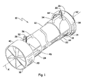
- a representative fluid filter module is generally shown at 10, including a tubular-shaped housing (12) extending along an axis (X) between opposing ends (14, 16) and defining an inner chamber (not shown).
- An end cap assembly (18, 20) is located at each end (14, 16) of the housing (12).
- Each end cap assembly (18, 20) comprises an annular base (22, 24) disposed concentrically about each end (14, 16) of the housing (12).
- the end caps assemblies (18, 20) each comprise a fluid port (26, 28) extending radially outward from the base in a direction perpendicular to the axis (X).
- the fluid ports (26, 28) are cylindrical and each define a passageway (30, 32) which is in fluid communication with the inner chamber of the housing (12).
- a handle comprising an L-shaped elongated gripping member (34, 36) extends from the fluid port (26, 28) to the base (22, 24) and defines an opening adapted for handling the module.
- the length of the elongated gripping member is preferably at least 50 mm and more preferably at least 100 mm.
- the end cap assemblies (18, 20) further include end caps (38, 40) which are secured to the base (22, 24) e.g. via matching threads, and which define outer chambers (shown in Figure 2 ).
- a "top" end cap (38) includes an outer concave periphery including a centrally located fluid channel (42) extending axially from the base (22), whereas a “bottom” end cap (40) includes a flat planner surface adapted for supporting the module in a vertical orientation.
- the end cap assemblies (18, 20) may further include one or more optional bosses (44, 44', 46) (shown in phantom).
- Each boss (44, 44', 46) comprises a raised side wall or annulus which defines a passageway to the inner chamber of the module (10) along with a top plate.
- the top plate prevents fluid communication with the inner chamber until such time as the top plate is removed, e.g. by drilling, to form a fluid port.
- the resulting fluid port may be connected, e.g. via mating threads, to a fluid source, e.g. pressurized gas, negative pressure, etc.
- one or more bosses (44, 44') may be positioned about a base (22, 24) of an end cap assembly (18, 20).
- the inclusion of multiple bosses allows the module (10) to be interconnected with fluid lines in a variety of different configurations, i.e. the sealed boss located closest to a desired fluid source may be tapped while the other bosses remained sealed.
- a plurality of bosses (44, 44') are aligned concentrically about the base (22, 24) along a plane bisecting the axis (X) of the module (10).
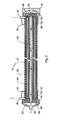
- FIG. 2 is a partially cut-away perspective view of the embodiment of Figure 1 .
- a plurality of semi-permeable hollow fibers (48) are orientated along the axis (X) within an inner chamber (50) of the housing (12).
- the opposing ends of the hollow fibers (48) are sealed from the inner chamber (50) by a mass of potting material (52, 54), (e.g. polyurethane, epoxy, silicone) but open and in fluid communications with outer chambers (56, 58) located within each end cap assembly (18, 20).
- the outer chambers (56, 58) are in fluid communication with each other by way of a center tube (60) extending centrally along the axis (X) of the module (10).
- pressurized feed fluid e.g.
- untreated water enters the inner chamber (50) by way of fluid port (28) and flows along the length of the hollow fibers (48).
- a portion of the feed fluid passes through semi-permeable membrane (e.g. hollow fibers (48) and travels to the outer chambers (56, 58) of the end cap assemblies (18, 20) where it ultimately exits the module (12) by one or more fluid channels (42), as generally shown by solid arrows.
- permeate (i.e. filtered fluid) of both outer chambers (56, 58) exits the module from a common fluid channel (42).
- each outer chamber (56, 58) may include a separate fluid channel (not shown).
- the second fluid port (26) When operating in dead-end mode, the second fluid port (26) is sealed; whereas when operating in cross-flow mode (arrow shown in phantom) the second fluid port (26) is open and provides an outlet for concentrated feed fluid to exit the module.
- both ends of the hollow fibers (48) are in fluid communication with outer chambers (56, 58).
- the hollow fibers (48) may be sealed at one end (e.g. end (16)).
- the module While described as operating "outside-in” mode (i.e. feed liquid contacting the outside of the hollow fiber membranes), the module may alternatively be operated in "inside-out” mode wherein feed fluid is introduced inside the lumen portion of the hollow fibers. While feed fluid is typically introduced into the module under pressure, the module may alternatively be operated by applying negative pressure to the permeate side of the semi-permeable membrane, or a combination of both positive and negative pressure.
- Figures 3-A, B, C and D are partially cut-away elevational views of various embodiments of end cap assemblies for use in connection with the subject fluid filter module.
- Figure 3-A illustrates an L-shaped elongated gripping member (34) extending from a fluid port (26) to a base (22) of an end cap assembly (18).
- the gripping member (34), fluid port (26) and base (22) collective form a rectangular opening adapted for receiving the fingers or hand of an operator.
- the outer edges of the opening may be rounded.
- Figure 3-B illustrates a straight shaped elongated gripping member (34) including a triangular shaped opening.
- Figure 3-C illustrates a curved shaped elongated gripping member (34).
- Figure 3-D illustrates an elongated gripping member (34) including an undulating grip surface (62).
Landscapes
- Chemical & Material Sciences (AREA)
- Chemical Kinetics & Catalysis (AREA)
- Separation Using Semi-Permeable Membranes (AREA)
Claims (6)
- Ein Fluidfiltermodul (10), das Folgendes beinhaltet:ein röhrenförmiges Gehäuse (12), das sich entlang einer Achse zwischen zwei gegenüberliegenden Enden erstreckt und eine innere Kammer (50) definiert;mindestens eine semipermeable Membran, die sich innerhalb der inneren Kammer (50) befindet,eine Endkappenanordnung (18, 20), die Folgendes beinhaltet:eine Basis (22, 24), die konzentrisch um ein Ende des Gehäuses (12) angeordnet ist, undeinen Fluidanschluss (26, 28), der sich von der Basis (22, 24) radial nach außen erstreckt, wobei der Fluidanschluss (26, 28) einen Durchgang (30, 32) inFluidkommunikation mit der inneren Kammer (50) definiert,dadurch gekennzeichnet, dass das Filtermodul (10) einen Griff umfasst, der ein längliches Greifteil (34, 36) beinhaltet, welches sich von der Basis (22, 24) zu dem Fluidanschluss (26, 28) erstreckt und eine Öffnung definiert, die zum Handhaben des Filtermoduls (10) angepasst ist.
- Fluidfiltermodul gemäß Anspruch 1, wobei die Basis (22, 24), der Fluidanschluss (26, 28) und der Griff eine integrale ausgeformte Struktur beinhalten.
- Fluidfiltermodul gemäß Anspruch 1, wobei das längliche Greifteil (34, 36) eine L-förmige Struktur beinhaltet.
- Fluidfiltermodul gemäß Anspruch 1, wobei sich an jedem Ende (14, 16) des Gehäuses (12) eine Endkappenanordnung (18, 20) befindet und wobei mindestens eine Endkappenanordnung (18, 20) ferner einen Fluidkanal (42) beinhaltet, der sich von der Basis (22, 24) axial nach außen erstreckt.
- Fluidfiltermodul gemäß Anspruch 1, wobei sich an jedem Ende (14, 16) des Gehäuses (12) eine Endkappenanordnung (18, 20) befindet und wobei beide Endkappenanordnungen (18, 20) einen Griff umfassen.
- Fluidfiltermodul gemäß Anspruch 1, wobei die semipermeable Membran eine Vielzahl von hohlen Fasern (48) beinhaltet.
Applications Claiming Priority (2)
| Application Number | Priority Date | Filing Date | Title |
|---|---|---|---|
| US12/862,872 US8261919B2 (en) | 2010-08-25 | 2010-08-25 | Fluid filter module including handle |
| PCT/US2011/046069 WO2012027070A1 (en) | 2010-08-25 | 2011-08-01 | Fluid filter module including handle |
Publications (2)
| Publication Number | Publication Date |
|---|---|
| EP2585200A1 EP2585200A1 (de) | 2013-05-01 |
| EP2585200B1 true EP2585200B1 (de) | 2014-05-14 |
Family
ID=44509664
Family Applications (1)
| Application Number | Title | Priority Date | Filing Date |
|---|---|---|---|
| EP11748522.7A Not-in-force EP2585200B1 (de) | 2010-08-25 | 2011-08-01 | Fluidfiltermodul mit griff |
Country Status (5)
| Country | Link |
|---|---|
| US (1) | US8261919B2 (de) |
| EP (1) | EP2585200B1 (de) |
| CN (1) | CN103068471B (de) |
| AU (1) | AU2011293758B2 (de) |
| WO (1) | WO2012027070A1 (de) |
Families Citing this family (5)
| Publication number | Priority date | Publication date | Assignee | Title |
|---|---|---|---|---|
| US10583401B2 (en) * | 2013-02-15 | 2020-03-10 | Advanced Hydro Inc | Integrated ultrafiltration and reverse osmosis desalination systems |
| USD753788S1 (en) * | 2013-05-31 | 2016-04-12 | Kx Technologies Llc | Handle end of filter cartridge |
| USD752707S1 (en) * | 2013-05-31 | 2016-03-29 | Kx Technologies Llc | Filter cartridge with handle end |
| EP3359272A4 (de) * | 2015-10-08 | 2019-07-24 | Dow Global Technologies, LLC | Hohlfasermembranmodul mit konzentratverteiler |
| BR112018008902B1 (pt) | 2015-11-06 | 2022-10-18 | Dow Global Technologies Llc | Método para recuperar óleo a partir de uma formação de óleo |
Family Cites Families (19)
| Publication number | Priority date | Publication date | Assignee | Title |
|---|---|---|---|---|
| SE441236B (sv) | 1984-06-18 | 1985-09-23 | Gambro Dialysatoren | Forfarande for framstellning av en anordning innefattande en halfiberbunt |
| US4609463A (en) | 1984-11-30 | 1986-09-02 | Nimbus Water Systems, Inc. | Water purification device |
| US5151180A (en) | 1989-10-17 | 1992-09-29 | Cuno, Incorporated | Radial and axial flow stage filter device |
| US5055198A (en) | 1990-03-07 | 1991-10-08 | Shettigar U Ramakrishna | Autologous blood recovery membrane system and method |
| US5211846A (en) * | 1990-07-30 | 1993-05-18 | Pleatco Electronic & Filter Corp. | Replacement filter cartridge assembly |
| US5328606A (en) | 1993-04-08 | 1994-07-12 | Travis Warren | Spin on oil filter with extendible handle |
| US5470469A (en) * | 1994-09-16 | 1995-11-28 | E. I. Du Pont De Nemours And Company | Hollow fiber cartridge |
| AU7578701A (en) * | 2000-08-02 | 2002-02-18 | Toray Industries, Inc. | Hollow yarn membrane module, hollow yarn membrane module unit, and method of producing hollow yarn membrane modules |
| MXPA03008974A (es) * | 2001-04-02 | 2004-10-15 | Donaldson Co Inc | Filtro de cartucho tipo cubilete que tiene mecanismo de interbloqueo y metodos. |
| US6827846B2 (en) | 2001-07-25 | 2004-12-07 | Parker-Hannifin Corporation | Filter element change indicator handle |
| GB2389323B (en) * | 2002-06-07 | 2005-08-17 | Baldwin Filters Inc | Environmentally friendly filter cartridge |
| NL1024557C2 (nl) | 2003-10-16 | 2005-04-20 | Membracon Filtration B V | Filterinrichting voor het scheiden van een deeltjeshoudende vloeistof in een concentraat en een permeaat. |
| US20050279716A1 (en) | 2004-06-22 | 2005-12-22 | Veolia Water Uk Plc | Water filter module handling apparatus |
| DE602005021799D1 (de) | 2004-09-29 | 2010-07-22 | 3M Innovative Properties Co | Standgerät-wasserfiltersystem |
| CN101351261A (zh) * | 2005-12-28 | 2009-01-21 | 株式会社吴羽 | 灌封剂、中空丝组件及其制造方法 |
| US20070227959A1 (en) * | 2006-03-31 | 2007-10-04 | Sinur Richard R | Filter cartridges and methods |
| US7837866B2 (en) | 2006-10-12 | 2010-11-23 | Burrows Bruce D | Drainless reverse osmosis water purification system |
| WO2008110165A1 (en) | 2007-03-09 | 2008-09-18 | Vestergaard Sa | Microporous filter with a halogen source |
| NL2002029C (nl) | 2008-09-26 | 2010-03-29 | X Flow Bv | Membraanfiltermodule met compacte aansluitingen. |
-
2010
- 2010-08-25 US US12/862,872 patent/US8261919B2/en not_active Expired - Fee Related
-
2011
- 2011-08-01 WO PCT/US2011/046069 patent/WO2012027070A1/en not_active Ceased
- 2011-08-01 EP EP11748522.7A patent/EP2585200B1/de not_active Not-in-force
- 2011-08-01 AU AU2011293758A patent/AU2011293758B2/en not_active Ceased
- 2011-08-01 CN CN201180041261.2A patent/CN103068471B/zh not_active Expired - Fee Related
Also Published As
| Publication number | Publication date |
|---|---|
| AU2011293758A1 (en) | 2013-02-14 |
| EP2585200A1 (de) | 2013-05-01 |
| US20120048796A1 (en) | 2012-03-01 |
| CN103068471B (zh) | 2016-02-17 |
| WO2012027070A1 (en) | 2012-03-01 |
| AU2011293758B2 (en) | 2014-12-11 |
| US8261919B2 (en) | 2012-09-11 |
| CN103068471A (zh) | 2013-04-24 |
Similar Documents
| Publication | Publication Date | Title |
|---|---|---|
| EP2585201B1 (de) | Fluidfiltermodul mit einer endkappe mit versiegeltem anschluss | |
| CN102510769B (zh) | 高压液体脱气薄膜接触器及制造和使用方法 | |
| CA2298393C (en) | Shell-less hollow fiber membrane fluid contactor | |
| CN103153427B (zh) | 液体脱气薄膜接触器、元件、系统及相关方法 | |
| EP2585200B1 (de) | Fluidfiltermodul mit griff | |
| EP2113297B1 (de) | Flüssigmembrankontaktor und Herstellungsverfahren dafür | |
| CN105142761A (zh) | 用于薄膜蒸馏或氨除去的薄膜接触器和系统及相关方法 | |
| JP5353693B2 (ja) | 濾過膜装置 | |
| US7635428B2 (en) | Hollow fiber membrane submodule and module including the same | |
| US20180229187A1 (en) | Hollow fiber membrane module including concentrate distributor | |
| US20040045890A1 (en) | Hollow fiber membrane cassette | |
| AU2002236864B2 (en) | Hollow fiber membrane cassette | |
| AU2002236864A1 (en) | Hollow fiber membrane cassette | |
| JP2004524140A5 (de) | ||
| US11572291B2 (en) | Membrane filter apparatus for liquid mixtures | |
| JPS6010645Y2 (ja) | 膜分離装置 | |
| CN106804105B (zh) | 包含通过可旋转保持环紧固的过滤模块的过滤组合件 | |
| AU2023384821A1 (en) | Multi-element filtration vessel | |
| WO2003086592A1 (fr) | Module de membranes a fibres creuses |
Legal Events
| Date | Code | Title | Description |
|---|---|---|---|
| PUAI | Public reference made under article 153(3) epc to a published international application that has entered the european phase |
Free format text: ORIGINAL CODE: 0009012 |
|
| 17P | Request for examination filed |
Effective date: 20130122 |
|
| AK | Designated contracting states |
Kind code of ref document: A1 Designated state(s): AL AT BE BG CH CY CZ DE DK EE ES FI FR GB GR HR HU IE IS IT LI LT LU LV MC MK MT NL NO PL PT RO RS SE SI SK SM TR |
|
| RIN1 | Information on inventor provided before grant (corrected) |
Inventor name: BURR, SCOTT, T. Inventor name: VOGEL, GAVIN, D. Inventor name: TURPIN, MATTHEW, J. Inventor name: MITTAG, MATTHEW, D. |
|
| DAX | Request for extension of the european patent (deleted) | ||
| 17Q | First examination report despatched |
Effective date: 20131128 |
|
| GRAP | Despatch of communication of intention to grant a patent |
Free format text: ORIGINAL CODE: EPIDOSNIGR1 |
|
| INTG | Intention to grant announced |
Effective date: 20140131 |
|
| GRAS | Grant fee paid |
Free format text: ORIGINAL CODE: EPIDOSNIGR3 |
|
| GRAA | (expected) grant |
Free format text: ORIGINAL CODE: 0009210 |
|
| AK | Designated contracting states |
Kind code of ref document: B1 Designated state(s): AL AT BE BG CH CY CZ DE DK EE ES FI FR GB GR HR HU IE IS IT LI LT LU LV MC MK MT NL NO PL PT RO RS SE SI SK SM TR |
|
| REG | Reference to a national code |
Ref country code: GB Ref legal event code: FG4D |
|
| REG | Reference to a national code |
Ref country code: AT Ref legal event code: REF Ref document number: 667820 Country of ref document: AT Kind code of ref document: T Effective date: 20140615 |
|
| REG | Reference to a national code |
Ref country code: IE Ref legal event code: FG4D |
|
| REG | Reference to a national code |
Ref country code: DE Ref legal event code: R096 Ref document number: 602011007065 Country of ref document: DE Effective date: 20140703 |
|
| REG | Reference to a national code |
Ref country code: NL Ref legal event code: T3 |
|
| REG | Reference to a national code |
Ref country code: AT Ref legal event code: MK05 Ref document number: 667820 Country of ref document: AT Kind code of ref document: T Effective date: 20140514 |
|
| REG | Reference to a national code |
Ref country code: LT Ref legal event code: MG4D |
|
| PG25 | Lapsed in a contracting state [announced via postgrant information from national office to epo] |
Ref country code: CY Free format text: LAPSE BECAUSE OF FAILURE TO SUBMIT A TRANSLATION OF THE DESCRIPTION OR TO PAY THE FEE WITHIN THE PRESCRIBED TIME-LIMIT Effective date: 20140514 Ref country code: FI Free format text: LAPSE BECAUSE OF FAILURE TO SUBMIT A TRANSLATION OF THE DESCRIPTION OR TO PAY THE FEE WITHIN THE PRESCRIBED TIME-LIMIT Effective date: 20140514 Ref country code: IS Free format text: LAPSE BECAUSE OF FAILURE TO SUBMIT A TRANSLATION OF THE DESCRIPTION OR TO PAY THE FEE WITHIN THE PRESCRIBED TIME-LIMIT Effective date: 20140914 Ref country code: LT Free format text: LAPSE BECAUSE OF FAILURE TO SUBMIT A TRANSLATION OF THE DESCRIPTION OR TO PAY THE FEE WITHIN THE PRESCRIBED TIME-LIMIT Effective date: 20140514 Ref country code: NO Free format text: LAPSE BECAUSE OF FAILURE TO SUBMIT A TRANSLATION OF THE DESCRIPTION OR TO PAY THE FEE WITHIN THE PRESCRIBED TIME-LIMIT Effective date: 20140814 Ref country code: GR Free format text: LAPSE BECAUSE OF FAILURE TO SUBMIT A TRANSLATION OF THE DESCRIPTION OR TO PAY THE FEE WITHIN THE PRESCRIBED TIME-LIMIT Effective date: 20140815 |
|
| PG25 | Lapsed in a contracting state [announced via postgrant information from national office to epo] |
Ref country code: RS Free format text: LAPSE BECAUSE OF FAILURE TO SUBMIT A TRANSLATION OF THE DESCRIPTION OR TO PAY THE FEE WITHIN THE PRESCRIBED TIME-LIMIT Effective date: 20140514 Ref country code: ES Free format text: LAPSE BECAUSE OF FAILURE TO SUBMIT A TRANSLATION OF THE DESCRIPTION OR TO PAY THE FEE WITHIN THE PRESCRIBED TIME-LIMIT Effective date: 20140514 Ref country code: LV Free format text: LAPSE BECAUSE OF FAILURE TO SUBMIT A TRANSLATION OF THE DESCRIPTION OR TO PAY THE FEE WITHIN THE PRESCRIBED TIME-LIMIT Effective date: 20140514 Ref country code: SE Free format text: LAPSE BECAUSE OF FAILURE TO SUBMIT A TRANSLATION OF THE DESCRIPTION OR TO PAY THE FEE WITHIN THE PRESCRIBED TIME-LIMIT Effective date: 20140514 Ref country code: HR Free format text: LAPSE BECAUSE OF FAILURE TO SUBMIT A TRANSLATION OF THE DESCRIPTION OR TO PAY THE FEE WITHIN THE PRESCRIBED TIME-LIMIT Effective date: 20140514 Ref country code: PL Free format text: LAPSE BECAUSE OF FAILURE TO SUBMIT A TRANSLATION OF THE DESCRIPTION OR TO PAY THE FEE WITHIN THE PRESCRIBED TIME-LIMIT Effective date: 20140514 Ref country code: AT Free format text: LAPSE BECAUSE OF FAILURE TO SUBMIT A TRANSLATION OF THE DESCRIPTION OR TO PAY THE FEE WITHIN THE PRESCRIBED TIME-LIMIT Effective date: 20140514 |
|
| PG25 | Lapsed in a contracting state [announced via postgrant information from national office to epo] |
Ref country code: PT Free format text: LAPSE BECAUSE OF FAILURE TO SUBMIT A TRANSLATION OF THE DESCRIPTION OR TO PAY THE FEE WITHIN THE PRESCRIBED TIME-LIMIT Effective date: 20140915 |
|
| PG25 | Lapsed in a contracting state [announced via postgrant information from national office to epo] |
Ref country code: EE Free format text: LAPSE BECAUSE OF FAILURE TO SUBMIT A TRANSLATION OF THE DESCRIPTION OR TO PAY THE FEE WITHIN THE PRESCRIBED TIME-LIMIT Effective date: 20140514 Ref country code: DK Free format text: LAPSE BECAUSE OF FAILURE TO SUBMIT A TRANSLATION OF THE DESCRIPTION OR TO PAY THE FEE WITHIN THE PRESCRIBED TIME-LIMIT Effective date: 20140514 Ref country code: CZ Free format text: LAPSE BECAUSE OF FAILURE TO SUBMIT A TRANSLATION OF THE DESCRIPTION OR TO PAY THE FEE WITHIN THE PRESCRIBED TIME-LIMIT Effective date: 20140514 Ref country code: BE Free format text: LAPSE BECAUSE OF FAILURE TO SUBMIT A TRANSLATION OF THE DESCRIPTION OR TO PAY THE FEE WITHIN THE PRESCRIBED TIME-LIMIT Effective date: 20140514 Ref country code: RO Free format text: LAPSE BECAUSE OF FAILURE TO SUBMIT A TRANSLATION OF THE DESCRIPTION OR TO PAY THE FEE WITHIN THE PRESCRIBED TIME-LIMIT Effective date: 20140514 Ref country code: SK Free format text: LAPSE BECAUSE OF FAILURE TO SUBMIT A TRANSLATION OF THE DESCRIPTION OR TO PAY THE FEE WITHIN THE PRESCRIBED TIME-LIMIT Effective date: 20140514 |
|
| REG | Reference to a national code |
Ref country code: DE Ref legal event code: R097 Ref document number: 602011007065 Country of ref document: DE |
|
| PLBE | No opposition filed within time limit |
Free format text: ORIGINAL CODE: 0009261 |
|
| STAA | Information on the status of an ep patent application or granted ep patent |
Free format text: STATUS: NO OPPOSITION FILED WITHIN TIME LIMIT |
|
| PG25 | Lapsed in a contracting state [announced via postgrant information from national office to epo] |
Ref country code: LU Free format text: LAPSE BECAUSE OF FAILURE TO SUBMIT A TRANSLATION OF THE DESCRIPTION OR TO PAY THE FEE WITHIN THE PRESCRIBED TIME-LIMIT Effective date: 20140801 Ref country code: MC Free format text: LAPSE BECAUSE OF FAILURE TO SUBMIT A TRANSLATION OF THE DESCRIPTION OR TO PAY THE FEE WITHIN THE PRESCRIBED TIME-LIMIT Effective date: 20140514 |
|
| REG | Reference to a national code |
Ref country code: CH Ref legal event code: PL |
|
| 26N | No opposition filed |
Effective date: 20150217 |
|
| PG25 | Lapsed in a contracting state [announced via postgrant information from national office to epo] |
Ref country code: LI Free format text: LAPSE BECAUSE OF NON-PAYMENT OF DUE FEES Effective date: 20140831 Ref country code: BE Free format text: LAPSE BECAUSE OF FAILURE TO SUBMIT A TRANSLATION OF THE DESCRIPTION OR TO PAY THE FEE WITHIN THE PRESCRIBED TIME-LIMIT Effective date: 20140831 Ref country code: CH Free format text: LAPSE BECAUSE OF NON-PAYMENT OF DUE FEES Effective date: 20140831 Ref country code: IT Free format text: LAPSE BECAUSE OF FAILURE TO SUBMIT A TRANSLATION OF THE DESCRIPTION OR TO PAY THE FEE WITHIN THE PRESCRIBED TIME-LIMIT Effective date: 20140514 |
|
| REG | Reference to a national code |
Ref country code: IE Ref legal event code: MM4A |
|
| REG | Reference to a national code |
Ref country code: DE Ref legal event code: R097 Ref document number: 602011007065 Country of ref document: DE Effective date: 20150217 |
|
| PG25 | Lapsed in a contracting state [announced via postgrant information from national office to epo] |
Ref country code: SI Free format text: LAPSE BECAUSE OF FAILURE TO SUBMIT A TRANSLATION OF THE DESCRIPTION OR TO PAY THE FEE WITHIN THE PRESCRIBED TIME-LIMIT Effective date: 20140514 |
|
| PG25 | Lapsed in a contracting state [announced via postgrant information from national office to epo] |
Ref country code: IE Free format text: LAPSE BECAUSE OF NON-PAYMENT OF DUE FEES Effective date: 20140801 |
|
| PG25 | Lapsed in a contracting state [announced via postgrant information from national office to epo] |
Ref country code: SM Free format text: LAPSE BECAUSE OF FAILURE TO SUBMIT A TRANSLATION OF THE DESCRIPTION OR TO PAY THE FEE WITHIN THE PRESCRIBED TIME-LIMIT Effective date: 20140514 |
|
| PG25 | Lapsed in a contracting state [announced via postgrant information from national office to epo] |
Ref country code: BG Free format text: LAPSE BECAUSE OF FAILURE TO SUBMIT A TRANSLATION OF THE DESCRIPTION OR TO PAY THE FEE WITHIN THE PRESCRIBED TIME-LIMIT Effective date: 20140514 Ref country code: MT Free format text: LAPSE BECAUSE OF FAILURE TO SUBMIT A TRANSLATION OF THE DESCRIPTION OR TO PAY THE FEE WITHIN THE PRESCRIBED TIME-LIMIT Effective date: 20140514 |
|
| REG | Reference to a national code |
Ref country code: FR Ref legal event code: PLFP Year of fee payment: 6 |
|
| PG25 | Lapsed in a contracting state [announced via postgrant information from national office to epo] |
Ref country code: HU Free format text: LAPSE BECAUSE OF FAILURE TO SUBMIT A TRANSLATION OF THE DESCRIPTION OR TO PAY THE FEE WITHIN THE PRESCRIBED TIME-LIMIT; INVALID AB INITIO Effective date: 20110801 Ref country code: TR Free format text: LAPSE BECAUSE OF FAILURE TO SUBMIT A TRANSLATION OF THE DESCRIPTION OR TO PAY THE FEE WITHIN THE PRESCRIBED TIME-LIMIT Effective date: 20140514 |
|
| REG | Reference to a national code |
Ref country code: FR Ref legal event code: PLFP Year of fee payment: 7 |
|
| REG | Reference to a national code |
Ref country code: FR Ref legal event code: PLFP Year of fee payment: 8 |
|
| PG25 | Lapsed in a contracting state [announced via postgrant information from national office to epo] |
Ref country code: MK Free format text: LAPSE BECAUSE OF FAILURE TO SUBMIT A TRANSLATION OF THE DESCRIPTION OR TO PAY THE FEE WITHIN THE PRESCRIBED TIME-LIMIT Effective date: 20140514 |
|
| PG25 | Lapsed in a contracting state [announced via postgrant information from national office to epo] |
Ref country code: AL Free format text: LAPSE BECAUSE OF FAILURE TO SUBMIT A TRANSLATION OF THE DESCRIPTION OR TO PAY THE FEE WITHIN THE PRESCRIBED TIME-LIMIT Effective date: 20140514 |
|
| P01 | Opt-out of the competence of the unified patent court (upc) registered |
Effective date: 20230528 |
|
| PGFP | Annual fee paid to national office [announced via postgrant information from national office to epo] |
Ref country code: NL Payment date: 20230719 Year of fee payment: 13 |
|
| PGFP | Annual fee paid to national office [announced via postgrant information from national office to epo] |
Ref country code: GB Payment date: 20230629 Year of fee payment: 13 |
|
| PGFP | Annual fee paid to national office [announced via postgrant information from national office to epo] |
Ref country code: FR Payment date: 20230703 Year of fee payment: 13 Ref country code: DE Payment date: 20230703 Year of fee payment: 13 |
|
| REG | Reference to a national code |
Ref country code: DE Ref legal event code: R119 Ref document number: 602011007065 Country of ref document: DE |
|
| REG | Reference to a national code |
Ref country code: NL Ref legal event code: MM Effective date: 20240901 |
|
| GBPC | Gb: european patent ceased through non-payment of renewal fee |
Effective date: 20240801 |
|
| PG25 | Lapsed in a contracting state [announced via postgrant information from national office to epo] |
Ref country code: NL Free format text: LAPSE BECAUSE OF NON-PAYMENT OF DUE FEES Effective date: 20240901 |
|
| PG25 | Lapsed in a contracting state [announced via postgrant information from national office to epo] |
Ref country code: DE Free format text: LAPSE BECAUSE OF NON-PAYMENT OF DUE FEES Effective date: 20250301 |
|
| PG25 | Lapsed in a contracting state [announced via postgrant information from national office to epo] |
Ref country code: GB Free format text: LAPSE BECAUSE OF NON-PAYMENT OF DUE FEES Effective date: 20240801 |
|
| PG25 | Lapsed in a contracting state [announced via postgrant information from national office to epo] |
Ref country code: FR Free format text: LAPSE BECAUSE OF NON-PAYMENT OF DUE FEES Effective date: 20240831 |