EP2585201B1 - Fluidfiltermodul mit einer endkappe mit versiegeltem anschluss - Google Patents
Fluidfiltermodul mit einer endkappe mit versiegeltem anschluss Download PDFInfo
- Publication number
- EP2585201B1 EP2585201B1 EP11749283.5A EP11749283A EP2585201B1 EP 2585201 B1 EP2585201 B1 EP 2585201B1 EP 11749283 A EP11749283 A EP 11749283A EP 2585201 B1 EP2585201 B1 EP 2585201B1
- Authority
- EP
- European Patent Office
- Prior art keywords
- fluid
- end cap
- base
- filter module
- module
- Prior art date
- Legal status (The legal status is an assumption and is not a legal conclusion. Google has not performed a legal analysis and makes no representation as to the accuracy of the status listed.)
- Active
Links
Images

Classifications
-
- B—PERFORMING OPERATIONS; TRANSPORTING
- B01—PHYSICAL OR CHEMICAL PROCESSES OR APPARATUS IN GENERAL
- B01D—SEPARATION
- B01D65/00—Accessories or auxiliary operations, in general, for separation processes or apparatus using semi-permeable membranes
-
- B—PERFORMING OPERATIONS; TRANSPORTING
- B01—PHYSICAL OR CHEMICAL PROCESSES OR APPARATUS IN GENERAL
- B01D—SEPARATION
- B01D2313/00—Details relating to membrane modules or apparatus
- B01D2313/10—Specific supply elements
-
- B—PERFORMING OPERATIONS; TRANSPORTING
- B01—PHYSICAL OR CHEMICAL PROCESSES OR APPARATUS IN GENERAL
- B01D—SEPARATION
- B01D2313/00—Details relating to membrane modules or apparatus
- B01D2313/12—Specific discharge elements
-
- B—PERFORMING OPERATIONS; TRANSPORTING
- B01—PHYSICAL OR CHEMICAL PROCESSES OR APPARATUS IN GENERAL
- B01D—SEPARATION
- B01D2313/00—Details relating to membrane modules or apparatus
- B01D2313/20—Specific housing
- B01D2313/201—Closed housing, vessels or containers
-
- B—PERFORMING OPERATIONS; TRANSPORTING
- B01—PHYSICAL OR CHEMICAL PROCESSES OR APPARATUS IN GENERAL
- B01D—SEPARATION
- B01D2313/00—Details relating to membrane modules or apparatus
- B01D2313/20—Specific housing
- B01D2313/205—Specific housing characterised by the shape
-
- B—PERFORMING OPERATIONS; TRANSPORTING
- B01—PHYSICAL OR CHEMICAL PROCESSES OR APPARATUS IN GENERAL
- B01D—SEPARATION
- B01D2313/00—Details relating to membrane modules or apparatus
- B01D2313/20—Specific housing
- B01D2313/206—Specific housing characterised by the material
- B01D2313/2061—Organic, e.g. polymeric material
-
- B—PERFORMING OPERATIONS; TRANSPORTING
- B01—PHYSICAL OR CHEMICAL PROCESSES OR APPARATUS IN GENERAL
- B01D—SEPARATION
- B01D2313/00—Details relating to membrane modules or apparatus
- B01D2313/20—Specific housing
- B01D2313/206—Specific housing characterised by the material
- B01D2313/2062—Inorganic material
Definitions
- the invention is directed toward fluid filter modules and associated component parts.
- Fluid filter modules are used in a wide variety of applications ranging from industrial processing of liquids and gases to residential purification of drinking water.
- Filter modules typically include a tubular-shaped housing defining an inner chamber with one or more fluid ports located near each end of the housing. In operation, fluid enters the module via a port and passes through a separation medium (e.g. semi-permeable membrane) located within the inner chamber. Fluid passing through the membrane exits the module by way of a separate fluid port, typically located at the opposite end of the module.
- a separation medium e.g. semi-permeable membrane
- Fluid passing through the membrane exits the module by way of a separate fluid port, typically located at the opposite end of the module.
- Various modes of operation are known including dead-end flow and cross-flow modes within which a filter is located.
- Filter modules may also include additional fluid ports or channels including inlets for introducing liquid or gas for cleaning the module.
- modules examples include DOWTM Ultrafiltration module models: SFP-2860, SFP-2880, SFD-2860 and SFD-2880 available from The Dow Chemical Corporation.
- These filter modules include semi-permeable hollow fiber membranes design for ultrafiltration-type applications such as the treatment of water.
- the above-mentioned modules include fluid ports that are molded as an integral part of an end cap assembly mounted on each end of the module housing. As fluid ports are located at fixed locations about the module, installation configurations can be limited. This can be particularly problematic when installing modules within confined locations, as part of assemblies including a plurality of modules aligned in close proximity, or where placement of fluid inlet and outlet lines are limited.
- the present invention is directed toward fluid filter modules and associated component parts along with methods for making and using the same.
- the present filter modules include a tubular housing extending along an axis between two opposing ends which defines an inner chamber.
- WO97/35125 and EP 1335162 disclose housings which are provided with additional bores if necessary.
- US5327862 discloses radially extending connectors closed by screw caps.
- the module further includes at least one an end cap assembly comprising a base disposed concentrically about an end of the housing, a fluid port extending radially outward from the base, and at least one sealed boss extending radially outward from the base, wherein the base, fluid port and sealed boss comprise an integral molded structure.
- the term "filter” is intended to describe a module capable of separating constituents based upon a wide variety of separation mechanisms including but not limited to: pore flow, solution-diffusion, ion exchange, adsorption and chelation.
- the present filter module is applicable for "filtering" a wide range of fluids including both gases and liquids. Examples of common liquid-based separations include organic and aqueous-based feeds.
- the present filter module may include a wide variety of separation mediums including membrane-based modules (e.g. spiral wound, hollow fiber, capillary and tubular membrane modules or “elements”) and media-based modules (e.g. a cartridge of granular-type material such as ion exchange resin, adsorbent media, e.g. carbon, titanium oxide and the like).
- membrane-based modules e.g. spiral wound, hollow fiber, capillary and tubular membrane modules or "elements”
- media-based modules e.g. a cartridge of granular-type material such as ion exchange resin, adsorbent media, e.g. carbon, titanium oxide and the like.
- Representative semi-permeable membranes include those made from: polysulfones, polyether sulfones, polyvinylidene fluoride, polyamides, polyacrylonitrile, etc.
- the subject module may be used in a wide range of applications including but not limited to microfiltration (MF), ultrafiltration (UF
- the module includes at least one semi-permeable membrane located within an inner chamber of the housing.
- a plurality of semi-permeable hollow fiber membranes are orientated axially within the inner chamber.
- the ends of the hollow fibers may be sealed from the inner chamber by way of known "potting" techniques wherein one or both ends of the hollow fibers remain open and in fluid communication one or more outer chambers formed within the end cap assembly.
- the present filter module preferably comprises a tubular-shaped housing, (e.g. an elongated shell having a length greater than its width), extending along an axis between two opposing ends and defining an inner chamber.
- the outer periphery of the filter module is cylindrically-shaped having a circular cross-section.
- the housing may have a polygonal cross-section.
- the housing may be constructed from a wide variety of materials, e.g. plastics, ceramics, metals, etc., however, in one set of preferred embodiments the housing is made from an injection moldable plastic such as polyvinyl chloride (PVC) or acrylonitrile butadiene styrene (ABS).
- PVC polyvinyl chloride
- ABS acrylonitrile butadiene styrene
- the filter module further comprises an end cap assembly including a base which is concentrically disposed about an end of the housing.
- An end cap assembly is preferably located at each end of the module.
- the inner periphery of the base of the assembly includes a matching or complementary configuration with that of the outer periphery of the end of the housing such that the base can be slid, tightly fitted and preferably sealed about the end of the housing.
- the base may be secured to the housing via mechanical means, e.g. pressure fit, clamps, matching threads, etc., or may be adhered such as by way of ultrasonic welding, spin welding, adhesive, etc., or combinations of such techniques.
- the end cap assembly further includes a fluid port extending radially outward from the base (i.e. in a direction perpendicular to the axis defined by the length of the housing).
- the fluid port comprises a raised nozzle-like structure including a passageway which is in fluid communication with the inner chamber of the housing.
- the end cap assembly may be constructed from a wide variety of materials, e.g. plastics, ceramics, metals, etc., however, in a preferred set of embodiments the housing is made from an injection moldable plastic such as polyvinyl chloride (PVC) or acrylonitrile butadiene styrene (ABS).
- PVC polyvinyl chloride
- ABS acrylonitrile butadiene styrene
- the end cap assembly may include additional fluid inlets and outlets of various orientations.
- the end cap assembly also includes a fluid port (i.e. "channel”) extending axially outward from the base.
- the filter module may include an optional handle comprising an elongated gripping member extending from the fluid port to the base of the end cap assembly.
- the elongated member, fluid port and base collectively form an opening (i.e. closed loop) which may be adapted for gripping or otherwise handling the module.
- the handle, base and fluid port comprise an integral molded structure, e.g. a single injection molded part.
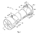
- a representative fluid filter module is generally shown at 10, including a tubular-shaped housing (12) extending along an axis (X) between opposing ends (14, 16) and defining an inner chamber (not shown).
- An end cap assembly (18, 20) is located at each end (14, 16) of the housing (12).
- Each end cap assembly (18, 20) comprises an annular base (22, 24) disposed concentrically about each end (14, 16) of the housing (12).
- the end caps assemblies (18, 20) each comprise a fluid port (26, 28) extending radially outward from the base in a direction perpendicular to the axis (X).
- the fluid ports (26, 28) are cylindrical and each define a passageway (30, 32) which is in fluid communication with the inner chamber of the housing (12).
- An optional handle comprising an L-shaped elongated gripping member (34, 36) (shown in phantom) extends from the fluid port (26, 28) to the base (22, 24) and defines an opening adapted for handling the module.
- the end cap assemblies (18, 20) further include end caps (38, 40) which are secured to the base (22, 24) e.g. via matching threads, and which define outer chambers (shown in Figure 2 ).
- a "top" end cap (38) includes an outer concave periphery including a centrally located fluid channel (42) extending axially from the base (22), whereas a “bottom” end cap (40) includes a flat planar surface adapted for supporting the module in a vertical orientation.
- At least one end cap assembly (18, 20) further includes one or more sealed bosses (44, 44', 46) extending radially outward from the base (22, 24).
- Each boss comprises a raised wall or annulus defining a passageway to the inner chamber of the module (10) along with a top plate in sealing engagement with the raised wall.
- the top plate prevents fluid communication with the inner chamber until such time as the top plate is removed, e.g. by drilling, to form a fluid port.
- the sealed bosses (44, 44', 46) provide structural support to the base (22, 24) during and after the removal of the top plate.
- the sealed bosses (44, 44', 46) are molded as an integral structure along with the base (22, 24) of the end cap assembly (18, 20). Once the top plate or portion thereof is removed, the resulting fluid port may be connected, e.g. via mating threads, to a fluid source, e.g. pressurized gas, negative pressure, etc.
- a fluid source e.g. pressurized gas, negative pressure, etc.
- one or more sealed bosses (44, 44') may be positioned about a base (22) of an end cap assembly (18).
- the inclusion of multiple bosses allows the module (10) to be interconnected with fluid lines in a variety of different configurations, i.e. the boss located closest to a desired fluid source may be tapped while the other bosses remained sealed.
- a plurality of bosses (44, 44') are aligned concentrically about the base (22) along a plane bisecting the axis (X) of the module (10).
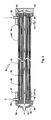
- FIG. 2 is a partially cut-away perspective view of the embodiment of Figure 1 .
- a plurality of semi-permeable hollow fibers (48) are orientated along the axis (X) within an inner chamber (50) of the housing (12).
- the opposing ends of the hollow fibers (48) are sealed from the inner chamber (50) by a mass of potting material (52, 54), (e.g. polyurethane, epoxy, silicone) but open and in fluid communications with outer chambers (56, 58) located within each end cap assembly (18, 20).
- the outer chambers (56, 58) are in fluid communication with each other by way of a center tube (60) extending centrally along the axis (X) of the module (10).
- pressurized feed fluid e.g.
- untreated water enters the inner chamber (50) by way of fluid port (28) and flows along the length of the hollow fibers (48).
- a portion of the feed fluid passes through semi-permeable membrane (e.g. hollow fibers (48) and travels to the outer chambers (56, 58) of the end cap assemblies (18, 20) where it ultimately exits the module (12) by one or more fluid channels (42), as generally shown by solid arrows.
- permeate (i.e. filtered fluid) of both outer chambers (56, 58) exits the module from a common fluid channel (42).
- each outer chamber (56, 58) may include a separate fluid channel (not shown).
- Figure 3 shows an enlarged perspective view of the end cap assembly (18) including a base (22), end cap (38) and fluid channel (42).
- the base (22) includes a fluid port (26), optional handle (34) and sealed bosses (44, 44').
- Each sealed boss (44, 44') includes a raised wall or "annulus" (62) extending radially outward from the base (22) which defines a passageway (not shown) to the inner chamber of the module. While shown as having a circular configuration, the sealed boss may have an alternative configuration, e.g. polygonal, elliptical, etc.
- Each sealed boss (44, 44') further includes a top plate (64) in sealing engagement with the raised wall (62).
- the top plate (64) prevents fluid passage through the passageway defined by the raised wall (62) until such time as the top plate (64) or portion thereof is removed, such as by way of drilling away a portion of the top plate.
- the top plate (64) preferably defines a flat surface.
- the flat surface of the top plate (64) provides a planar contact surface which facilitates drilling or other operations designed to unseal the boss (44, 44').
- the top plate (64) includes a centrally located indent (66) which facilitates proper alignment of drilling operations. Once a portion of the top plate has been removed, e.g. via drilling through the top plate, the resulting passageway may be threaded or otherwise adapted for receiving a fluid line.
- the raised wall (62) of the boss (44, 44') provides added strength to the base (22) during drilling, tapping or similar operations directed toward unsealing the boss (44, 44').
- the top plate (64) and raised wall (62) are preferably integrally molded with the fluid port (26) and base (22) and form a single integrated part.
- the sealed bosses (44, 44') are aligned concentrically about the base (22) along a plane bisecting the axis (X) of the module.
- the sealed bosses (44, 44') are preferable located in close proximity to the fluid port (26); e.g. with a common arc section comprising less than half the total circumference of the base (18).
- the top plates of one or more sealed bosses may be tapped and connected with a source of pressurized fluid or vacuum.
- a tapped boss in connected with a source of pressurized air which can be selectively initiated during washing or backwashing operations.
Landscapes
- Chemical & Material Sciences (AREA)
- Chemical Kinetics & Catalysis (AREA)
- Separation Using Semi-Permeable Membranes (AREA)
Claims (7)
- Ein Fluidfiltermodul, das Folgendes beinhaltet:ein röhrenförmiges Gehäuse, das sich entlang einer Achse zwischen zwei gegenüberliegenden Enden erstreckt und eine innere Kammer definiert, in der sich ein Filter befindet,eine Endkappenanordnung, die Folgendes beinhaltet:eine Basis, die konzentrisch um ein Ende des Gehäuses angeordnet ist, eine Fluidöffnung, die sich von der Basis radial nach außen erstreckt, wobei die Fluidöffnung einen Durchgang in Fluidkommunikation mit der inneren Kammer definiert, dadurch gekennzeichnet, dasssich mindestens ein abgedichteter Vorsprung von der Basis radial nach außen erstreckt und einen Durchgang zu der inneren Kammer definiert, wobei der abgedichtete Vorsprung eine obere Platte beinhaltet, die die Fluidkommunikation mit der inneren Kammer verhindert, und wobei die Basis, die Fluidöffnung und der abgedichtete Vorsprung eine integrale geformte Struktur beinhalten.
- Fluidfiltermodul gemäß Anspruch 1, wobei die Endkappenanordnung eine Vielzahl von abgedichteten Vorsprüngen beinhaltet.
- Fluidfiltermodul gemäß Anspruch 1, wobei die Endkappenanordnung eine Vielzahl von abgedichteten Vorsprüngen beinhaltet, die entlang einer Ebene, welche die Achse des Moduls halbiert, konzentrisch um die Basis ausgerichtet sind.
- Fluidfiltermodul gemäß Anspruch 1, wobei der abgedichtete Vorsprung eine sich in der Mitte der oberen Platte befindende Vertiefung umfasst.
- Fluidfiltermodul gemäß Anspruch 1, wobei sich an jedem Ende des Gehäuses eine Endkappenanordnung befindet.
- Fluidfiltermodul gemäß Anspruch 1, wobei der Filter mindestens eine halbdurchlässige Membran beinhaltet.
- Fluidfiltermodul gemäß Anspruch 7, wobei die halbdurchlässige Membran eine Vielzahl von hohlen Fasern beinhaltet.
Applications Claiming Priority (2)
| Application Number | Priority Date | Filing Date | Title |
|---|---|---|---|
| US12/862,881 US8173018B2 (en) | 2010-08-25 | 2010-08-25 | Fluid filter module including sealed boss |
| PCT/US2011/046068 WO2012027069A1 (en) | 2010-08-25 | 2011-08-01 | Fluid filter module including end cap with sealed boss |
Publications (2)
| Publication Number | Publication Date |
|---|---|
| EP2585201A1 EP2585201A1 (de) | 2013-05-01 |
| EP2585201B1 true EP2585201B1 (de) | 2014-04-09 |
Family
ID=44515012
Family Applications (1)
| Application Number | Title | Priority Date | Filing Date |
|---|---|---|---|
| EP11749283.5A Active EP2585201B1 (de) | 2010-08-25 | 2011-08-01 | Fluidfiltermodul mit einer endkappe mit versiegeltem anschluss |
Country Status (5)
| Country | Link |
|---|---|
| US (1) | US8173018B2 (de) |
| EP (1) | EP2585201B1 (de) |
| CN (1) | CN103153445B (de) |
| AU (1) | AU2011293757B2 (de) |
| WO (1) | WO2012027069A1 (de) |
Families Citing this family (12)
| Publication number | Priority date | Publication date | Assignee | Title |
|---|---|---|---|---|
| KR101557544B1 (ko) * | 2012-12-29 | 2015-11-02 | 삼성에스디아이 주식회사 | 중공사막 모듈 |
| CN104226118B (zh) * | 2013-06-09 | 2019-01-08 | 陶氏环球技术有限责任公司 | 端盖包括一体阀的过滤器模块 |
| WO2014198015A1 (en) * | 2013-06-09 | 2014-12-18 | Dow Global Technologies Llc | Filter module with end caps including integral valves |
| JP6534392B2 (ja) * | 2014-02-03 | 2019-06-26 | ユーロサイダー エス.エイ.エス. ディ ミッリ オッタヴィオ アンド シー. | 中空繊維膜によって空気から窒素を分離するためのモジュール |
| US20150290589A1 (en) * | 2014-04-11 | 2015-10-15 | Parker-Hannifin Corporation | Encapsulating outer shell for membrane elements |
| USD752179S1 (en) | 2014-09-05 | 2016-03-22 | Red Origen, LLC | Interchangeable water filter base or portions thereof |
| USD760868S1 (en) | 2014-09-29 | 2016-07-05 | Red Origen, LLC | Water filter fitting |
| USD764626S1 (en) | 2015-03-26 | 2016-08-23 | Red Origen, LLC | Water filter fitting |
| USD764021S1 (en) | 2015-03-26 | 2016-08-16 | Red Origen, LLC | Fitting section of a water filter |
| USD762813S1 (en) | 2015-06-24 | 2016-08-02 | Red Origen, LLC | Fitting section of a water filter |
| USD774623S1 (en) | 2015-08-17 | 2016-12-20 | Red Origen, LLC | Water filter fitting |
| USD773607S1 (en) | 2015-08-17 | 2016-12-06 | Red Origin, LLC | Water filter fitting section |
Family Cites Families (13)
| Publication number | Priority date | Publication date | Assignee | Title |
|---|---|---|---|---|
| SE441236B (sv) | 1984-06-18 | 1985-09-23 | Gambro Dialysatoren | Forfarande for framstellning av en anordning innefattande en halfiberbunt |
| JPS61192309A (ja) | 1985-02-21 | 1986-08-26 | Asahi Chem Ind Co Ltd | 中空糸型モジユ−ル |
| US5151180A (en) | 1989-10-17 | 1992-09-29 | Cuno, Incorporated | Radial and axial flow stage filter device |
| US5055198A (en) | 1990-03-07 | 1991-10-08 | Shettigar U Ramakrishna | Autologous blood recovery membrane system and method |
| US5320238A (en) | 1992-06-10 | 1994-06-14 | Fib-R-Fit, Inc. | End closure method and construction for non-metallic pressure vessels |
| US5327862A (en) | 1993-05-28 | 1994-07-12 | K.J. Manufacturing Co. | Multi-port filter mounting adapter and fitting mounted to same for expediting removal of oil from internal combustion engine associated therewith and method for accomplishing same |
| US5720411A (en) | 1996-03-20 | 1998-02-24 | Advanced Structures, Inc. | Pressure vessels and end closures therefor |
| AU7578701A (en) * | 2000-08-02 | 2002-02-18 | Toray Industries, Inc. | Hollow yarn membrane module, hollow yarn membrane module unit, and method of producing hollow yarn membrane modules |
| EP1335162A3 (de) | 2002-02-06 | 2006-03-15 | Essef Corporation d.b.a. Pentair Water Treatment | Druckbehälter |
| NL1024557C2 (nl) | 2003-10-16 | 2005-04-20 | Membracon Filtration B V | Filterinrichting voor het scheiden van een deeltjeshoudende vloeistof in een concentraat en een permeaat. |
| CN101351261A (zh) | 2005-12-28 | 2009-01-21 | 株式会社吴羽 | 灌封剂、中空丝组件及其制造方法 |
| WO2008110165A1 (en) | 2007-03-09 | 2008-09-18 | Vestergaard Sa | Microporous filter with a halogen source |
| NL2002029C (nl) | 2008-09-26 | 2010-03-29 | X Flow Bv | Membraanfiltermodule met compacte aansluitingen. |
-
2010
- 2010-08-25 US US12/862,881 patent/US8173018B2/en active Active
-
2011
- 2011-08-01 EP EP11749283.5A patent/EP2585201B1/de active Active
- 2011-08-01 WO PCT/US2011/046068 patent/WO2012027069A1/en not_active Ceased
- 2011-08-01 CN CN201180041263.1A patent/CN103153445B/zh active Active
- 2011-08-01 AU AU2011293757A patent/AU2011293757B2/en active Active
Also Published As
| Publication number | Publication date |
|---|---|
| AU2011293757B2 (en) | 2014-11-06 |
| AU2011293757A1 (en) | 2013-02-14 |
| CN103153445A (zh) | 2013-06-12 |
| US8173018B2 (en) | 2012-05-08 |
| WO2012027069A1 (en) | 2012-03-01 |
| EP2585201A1 (de) | 2013-05-01 |
| US20120048795A1 (en) | 2012-03-01 |
| CN103153445B (zh) | 2015-03-04 |
Similar Documents
| Publication | Publication Date | Title |
|---|---|---|
| EP2585201B1 (de) | Fluidfiltermodul mit einer endkappe mit versiegeltem anschluss | |
| CA2298393C (en) | Shell-less hollow fiber membrane fluid contactor | |
| EP1974801A2 (de) | Kassettenartige Filtriervorrichtung | |
| US20070131604A1 (en) | Filter unit with deaerating mechanism | |
| US20180229187A1 (en) | Hollow fiber membrane module including concentrate distributor | |
| WO2009149228A1 (en) | A wafer-shaped hollow fiber module for in-line use in a piping system | |
| EP2585200B1 (de) | Fluidfiltermodul mit griff | |
| US20080257813A1 (en) | Cassette-style filtration apparatus | |
| US20040045890A1 (en) | Hollow fiber membrane cassette | |
| AU2002236864B2 (en) | Hollow fiber membrane cassette | |
| AU2002236864A1 (en) | Hollow fiber membrane cassette | |
| JP2004524140A5 (de) | ||
| KR101902458B1 (ko) | 중공사막 모듈 | |
| US11572291B2 (en) | Membrane filter apparatus for liquid mixtures | |
| US20210394122A1 (en) | Hollow-fiber membrane module | |
| CN106804105B (zh) | 包含通过可旋转保持环紧固的过滤模块的过滤组合件 | |
| US20220032236A1 (en) | Fluid separation element | |
| KR101486885B1 (ko) | 중공사막 고정 및 유체 분배용 캡 |
Legal Events
| Date | Code | Title | Description |
|---|---|---|---|
| PUAI | Public reference made under article 153(3) epc to a published international application that has entered the european phase |
Free format text: ORIGINAL CODE: 0009012 |
|
| 17P | Request for examination filed |
Effective date: 20130122 |
|
| AK | Designated contracting states |
Kind code of ref document: A1 Designated state(s): AL AT BE BG CH CY CZ DE DK EE ES FI FR GB GR HR HU IE IS IT LI LT LU LV MC MK MT NL NO PL PT RO RS SE SI SK SM TR |
|
| RIN1 | Information on inventor provided before grant (corrected) |
Inventor name: HALLAN, MATTHEW, J. Inventor name: VOGEL, GAVIN, D. Inventor name: TURPIN, MATTHEW, J. Inventor name: MITTAG, MATTHEW, D. Inventor name: BURR, SCOTT, T. |
|
| GRAP | Despatch of communication of intention to grant a patent |
Free format text: ORIGINAL CODE: EPIDOSNIGR1 |
|
| DAX | Request for extension of the european patent (deleted) | ||
| INTG | Intention to grant announced |
Effective date: 20131119 |
|
| GRAS | Grant fee paid |
Free format text: ORIGINAL CODE: EPIDOSNIGR3 |
|
| GRAA | (expected) grant |
Free format text: ORIGINAL CODE: 0009210 |
|
| AK | Designated contracting states |
Kind code of ref document: B1 Designated state(s): AL AT BE BG CH CY CZ DE DK EE ES FI FR GB GR HR HU IE IS IT LI LT LU LV MC MK MT NL NO PL PT RO RS SE SI SK SM TR |
|
| REG | Reference to a national code |
Ref country code: GB Ref legal event code: FG4D |
|
| REG | Reference to a national code |
Ref country code: AT Ref legal event code: REF Ref document number: 661022 Country of ref document: AT Kind code of ref document: T Effective date: 20140415 Ref country code: CH Ref legal event code: EP |
|
| REG | Reference to a national code |
Ref country code: IE Ref legal event code: FG4D |
|
| REG | Reference to a national code |
Ref country code: DE Ref legal event code: R096 Ref document number: 602011006099 Country of ref document: DE Effective date: 20140522 |
|
| REG | Reference to a national code |
Ref country code: NL Ref legal event code: T3 |
|
| REG | Reference to a national code |
Ref country code: AT Ref legal event code: MK05 Ref document number: 661022 Country of ref document: AT Kind code of ref document: T Effective date: 20140409 |
|
| REG | Reference to a national code |
Ref country code: LT Ref legal event code: MG4D |
|
| PG25 | Lapsed in a contracting state [announced via postgrant information from national office to epo] |
Ref country code: NO Free format text: LAPSE BECAUSE OF FAILURE TO SUBMIT A TRANSLATION OF THE DESCRIPTION OR TO PAY THE FEE WITHIN THE PRESCRIBED TIME-LIMIT Effective date: 20140709 Ref country code: GR Free format text: LAPSE BECAUSE OF FAILURE TO SUBMIT A TRANSLATION OF THE DESCRIPTION OR TO PAY THE FEE WITHIN THE PRESCRIBED TIME-LIMIT Effective date: 20140710 Ref country code: FI Free format text: LAPSE BECAUSE OF FAILURE TO SUBMIT A TRANSLATION OF THE DESCRIPTION OR TO PAY THE FEE WITHIN THE PRESCRIBED TIME-LIMIT Effective date: 20140409 Ref country code: LT Free format text: LAPSE BECAUSE OF FAILURE TO SUBMIT A TRANSLATION OF THE DESCRIPTION OR TO PAY THE FEE WITHIN THE PRESCRIBED TIME-LIMIT Effective date: 20140409 Ref country code: IS Free format text: LAPSE BECAUSE OF FAILURE TO SUBMIT A TRANSLATION OF THE DESCRIPTION OR TO PAY THE FEE WITHIN THE PRESCRIBED TIME-LIMIT Effective date: 20140809 Ref country code: BG Free format text: LAPSE BECAUSE OF FAILURE TO SUBMIT A TRANSLATION OF THE DESCRIPTION OR TO PAY THE FEE WITHIN THE PRESCRIBED TIME-LIMIT Effective date: 20140709 |
|
| PG25 | Lapsed in a contracting state [announced via postgrant information from national office to epo] |
Ref country code: RS Free format text: LAPSE BECAUSE OF FAILURE TO SUBMIT A TRANSLATION OF THE DESCRIPTION OR TO PAY THE FEE WITHIN THE PRESCRIBED TIME-LIMIT Effective date: 20140409 Ref country code: AT Free format text: LAPSE BECAUSE OF FAILURE TO SUBMIT A TRANSLATION OF THE DESCRIPTION OR TO PAY THE FEE WITHIN THE PRESCRIBED TIME-LIMIT Effective date: 20140409 Ref country code: PL Free format text: LAPSE BECAUSE OF FAILURE TO SUBMIT A TRANSLATION OF THE DESCRIPTION OR TO PAY THE FEE WITHIN THE PRESCRIBED TIME-LIMIT Effective date: 20140409 Ref country code: SE Free format text: LAPSE BECAUSE OF FAILURE TO SUBMIT A TRANSLATION OF THE DESCRIPTION OR TO PAY THE FEE WITHIN THE PRESCRIBED TIME-LIMIT Effective date: 20140409 Ref country code: LV Free format text: LAPSE BECAUSE OF FAILURE TO SUBMIT A TRANSLATION OF THE DESCRIPTION OR TO PAY THE FEE WITHIN THE PRESCRIBED TIME-LIMIT Effective date: 20140409 Ref country code: HR Free format text: LAPSE BECAUSE OF FAILURE TO SUBMIT A TRANSLATION OF THE DESCRIPTION OR TO PAY THE FEE WITHIN THE PRESCRIBED TIME-LIMIT Effective date: 20140409 Ref country code: ES Free format text: LAPSE BECAUSE OF FAILURE TO SUBMIT A TRANSLATION OF THE DESCRIPTION OR TO PAY THE FEE WITHIN THE PRESCRIBED TIME-LIMIT Effective date: 20140409 |
|
| PG25 | Lapsed in a contracting state [announced via postgrant information from national office to epo] |
Ref country code: PT Free format text: LAPSE BECAUSE OF FAILURE TO SUBMIT A TRANSLATION OF THE DESCRIPTION OR TO PAY THE FEE WITHIN THE PRESCRIBED TIME-LIMIT Effective date: 20140811 |
|
| REG | Reference to a national code |
Ref country code: DE Ref legal event code: R097 Ref document number: 602011006099 Country of ref document: DE |
|
| PG25 | Lapsed in a contracting state [announced via postgrant information from national office to epo] |
Ref country code: DK Free format text: LAPSE BECAUSE OF FAILURE TO SUBMIT A TRANSLATION OF THE DESCRIPTION OR TO PAY THE FEE WITHIN THE PRESCRIBED TIME-LIMIT Effective date: 20140409 Ref country code: CZ Free format text: LAPSE BECAUSE OF FAILURE TO SUBMIT A TRANSLATION OF THE DESCRIPTION OR TO PAY THE FEE WITHIN THE PRESCRIBED TIME-LIMIT Effective date: 20140409 Ref country code: BE Free format text: LAPSE BECAUSE OF FAILURE TO SUBMIT A TRANSLATION OF THE DESCRIPTION OR TO PAY THE FEE WITHIN THE PRESCRIBED TIME-LIMIT Effective date: 20140409 Ref country code: SK Free format text: LAPSE BECAUSE OF FAILURE TO SUBMIT A TRANSLATION OF THE DESCRIPTION OR TO PAY THE FEE WITHIN THE PRESCRIBED TIME-LIMIT Effective date: 20140409 Ref country code: RO Free format text: LAPSE BECAUSE OF FAILURE TO SUBMIT A TRANSLATION OF THE DESCRIPTION OR TO PAY THE FEE WITHIN THE PRESCRIBED TIME-LIMIT Effective date: 20140409 Ref country code: EE Free format text: LAPSE BECAUSE OF FAILURE TO SUBMIT A TRANSLATION OF THE DESCRIPTION OR TO PAY THE FEE WITHIN THE PRESCRIBED TIME-LIMIT Effective date: 20140409 |
|
| PLBE | No opposition filed within time limit |
Free format text: ORIGINAL CODE: 0009261 |
|
| STAA | Information on the status of an ep patent application or granted ep patent |
Free format text: STATUS: NO OPPOSITION FILED WITHIN TIME LIMIT |
|
| 26N | No opposition filed |
Effective date: 20150112 |
|
| PG25 | Lapsed in a contracting state [announced via postgrant information from national office to epo] |
Ref country code: MC Free format text: LAPSE BECAUSE OF FAILURE TO SUBMIT A TRANSLATION OF THE DESCRIPTION OR TO PAY THE FEE WITHIN THE PRESCRIBED TIME-LIMIT Effective date: 20140409 Ref country code: IT Free format text: LAPSE BECAUSE OF FAILURE TO SUBMIT A TRANSLATION OF THE DESCRIPTION OR TO PAY THE FEE WITHIN THE PRESCRIBED TIME-LIMIT Effective date: 20140409 Ref country code: LU Free format text: LAPSE BECAUSE OF FAILURE TO SUBMIT A TRANSLATION OF THE DESCRIPTION OR TO PAY THE FEE WITHIN THE PRESCRIBED TIME-LIMIT Effective date: 20140801 |
|
| REG | Reference to a national code |
Ref country code: CH Ref legal event code: PL |
|
| REG | Reference to a national code |
Ref country code: DE Ref legal event code: R097 Ref document number: 602011006099 Country of ref document: DE Effective date: 20150112 |
|
| PG25 | Lapsed in a contracting state [announced via postgrant information from national office to epo] |
Ref country code: CH Free format text: LAPSE BECAUSE OF NON-PAYMENT OF DUE FEES Effective date: 20140831 Ref country code: LI Free format text: LAPSE BECAUSE OF NON-PAYMENT OF DUE FEES Effective date: 20140831 |
|
| REG | Reference to a national code |
Ref country code: IE Ref legal event code: MM4A |
|
| PG25 | Lapsed in a contracting state [announced via postgrant information from national office to epo] |
Ref country code: SI Free format text: LAPSE BECAUSE OF FAILURE TO SUBMIT A TRANSLATION OF THE DESCRIPTION OR TO PAY THE FEE WITHIN THE PRESCRIBED TIME-LIMIT Effective date: 20140409 |
|
| PG25 | Lapsed in a contracting state [announced via postgrant information from national office to epo] |
Ref country code: IE Free format text: LAPSE BECAUSE OF NON-PAYMENT OF DUE FEES Effective date: 20140801 |
|
| PG25 | Lapsed in a contracting state [announced via postgrant information from national office to epo] |
Ref country code: SM Free format text: LAPSE BECAUSE OF FAILURE TO SUBMIT A TRANSLATION OF THE DESCRIPTION OR TO PAY THE FEE WITHIN THE PRESCRIBED TIME-LIMIT Effective date: 20140409 |
|
| PG25 | Lapsed in a contracting state [announced via postgrant information from national office to epo] |
Ref country code: CY Free format text: LAPSE BECAUSE OF FAILURE TO SUBMIT A TRANSLATION OF THE DESCRIPTION OR TO PAY THE FEE WITHIN THE PRESCRIBED TIME-LIMIT Effective date: 20140409 Ref country code: MT Free format text: LAPSE BECAUSE OF FAILURE TO SUBMIT A TRANSLATION OF THE DESCRIPTION OR TO PAY THE FEE WITHIN THE PRESCRIBED TIME-LIMIT Effective date: 20140409 |
|
| REG | Reference to a national code |
Ref country code: FR Ref legal event code: PLFP Year of fee payment: 6 |
|
| PG25 | Lapsed in a contracting state [announced via postgrant information from national office to epo] |
Ref country code: TR Free format text: LAPSE BECAUSE OF FAILURE TO SUBMIT A TRANSLATION OF THE DESCRIPTION OR TO PAY THE FEE WITHIN THE PRESCRIBED TIME-LIMIT Effective date: 20140409 Ref country code: HU Free format text: LAPSE BECAUSE OF FAILURE TO SUBMIT A TRANSLATION OF THE DESCRIPTION OR TO PAY THE FEE WITHIN THE PRESCRIBED TIME-LIMIT; INVALID AB INITIO Effective date: 20110801 |
|
| REG | Reference to a national code |
Ref country code: FR Ref legal event code: PLFP Year of fee payment: 7 |
|
| REG | Reference to a national code |
Ref country code: FR Ref legal event code: PLFP Year of fee payment: 8 |
|
| PG25 | Lapsed in a contracting state [announced via postgrant information from national office to epo] |
Ref country code: MK Free format text: LAPSE BECAUSE OF FAILURE TO SUBMIT A TRANSLATION OF THE DESCRIPTION OR TO PAY THE FEE WITHIN THE PRESCRIBED TIME-LIMIT Effective date: 20140409 |
|
| PG25 | Lapsed in a contracting state [announced via postgrant information from national office to epo] |
Ref country code: AL Free format text: LAPSE BECAUSE OF FAILURE TO SUBMIT A TRANSLATION OF THE DESCRIPTION OR TO PAY THE FEE WITHIN THE PRESCRIBED TIME-LIMIT Effective date: 20140409 |
|
| P01 | Opt-out of the competence of the unified patent court (upc) registered |
Effective date: 20230528 |
|
| REG | Reference to a national code |
Ref country code: NL Ref legal event code: PD Owner name: DDP SPECIALTY ELECTRONIC MATERIALS US, LLC; US Free format text: DETAILS ASSIGNMENT: CHANGE OF OWNER(S), ASSIGNMENT; FORMER OWNER NAME: THE DOW CHEMICAL COMPANY Effective date: 20241030 |
|
| REG | Reference to a national code |
Ref country code: DE Ref legal event code: R082 Ref document number: 602011006099 Country of ref document: DE Representative=s name: ABITZ & PARTNER PATENTANWAELTE MBB, DE Ref country code: DE Ref legal event code: R081 Ref document number: 602011006099 Country of ref document: DE Owner name: DDP SPECIALTY ELECTRONIC MATERIALS US, LLC, WI, US Free format text: FORMER OWNER: DOW GLOBAL TECHNOLOGIES LLC, MIDLAND, MICH., US |
|
| PGFP | Annual fee paid to national office [announced via postgrant information from national office to epo] |
Ref country code: NL Payment date: 20250704 Year of fee payment: 15 |
|
| PGFP | Annual fee paid to national office [announced via postgrant information from national office to epo] |
Ref country code: DE Payment date: 20250702 Year of fee payment: 15 |
|
| PGFP | Annual fee paid to national office [announced via postgrant information from national office to epo] |
Ref country code: GB Payment date: 20250703 Year of fee payment: 15 |
|
| PGFP | Annual fee paid to national office [announced via postgrant information from national office to epo] |
Ref country code: FR Payment date: 20250703 Year of fee payment: 15 |