EP2584993B1 - Op-abdecktuch mit reduzierung der magnetischen interferenz - Google Patents
Op-abdecktuch mit reduzierung der magnetischen interferenz Download PDFInfo
- Publication number
- EP2584993B1 EP2584993B1 EP11797447.7A EP11797447A EP2584993B1 EP 2584993 B1 EP2584993 B1 EP 2584993B1 EP 11797447 A EP11797447 A EP 11797447A EP 2584993 B1 EP2584993 B1 EP 2584993B1
- Authority
- EP
- European Patent Office
- Prior art keywords
- drape
- magnet
- magnetic
- sections
- cup
- Prior art date
- Legal status (The legal status is an assumption and is not a legal conclusion. Google has not performed a legal analysis and makes no representation as to the accuracy of the status listed.)
- Active
Links
Images



Classifications
-
- A—HUMAN NECESSITIES
- A61—MEDICAL OR VETERINARY SCIENCE; HYGIENE
- A61D—VETERINARY INSTRUMENTS, IMPLEMENTS, TOOLS, OR METHODS
- A61D1/00—Surgical instruments for veterinary use
-
- A—HUMAN NECESSITIES
- A61—MEDICAL OR VETERINARY SCIENCE; HYGIENE
- A61B—DIAGNOSIS; SURGERY; IDENTIFICATION
- A61B46/00—Surgical drapes
- A61B46/20—Surgical drapes specially adapted for patients
- A61B46/23—Surgical drapes specially adapted for patients with means to retain or hold surgical implements
-
- A—HUMAN NECESSITIES
- A61—MEDICAL OR VETERINARY SCIENCE; HYGIENE
- A61C—DENTISTRY; APPARATUS OR METHODS FOR ORAL OR DENTAL HYGIENE
- A61C19/00—Dental auxiliary appliances
-
- H—ELECTRICITY
- H01—ELECTRIC ELEMENTS
- H01F—MAGNETS; INDUCTANCES; TRANSFORMERS; SELECTION OF MATERIALS FOR THEIR MAGNETIC PROPERTIES
- H01F7/00—Magnets
- H01F7/02—Permanent magnets [PM]
- H01F7/0231—Magnetic circuits with PM for power or force generation
- H01F7/0252—PM holding devices
-
- A—HUMAN NECESSITIES
- A61—MEDICAL OR VETERINARY SCIENCE; HYGIENE
- A61B—DIAGNOSIS; SURGERY; IDENTIFICATION
- A61B17/00—Surgical instruments, devices or methods
- A61B2017/00831—Material properties
- A61B2017/00876—Material properties magnetic
-
- A—HUMAN NECESSITIES
- A61—MEDICAL OR VETERINARY SCIENCE; HYGIENE
- A61B—DIAGNOSIS; SURGERY; IDENTIFICATION
- A61B90/00—Instruments, implements or accessories specially adapted for surgery or diagnosis and not covered by any of the groups A61B1/00 - A61B50/00, e.g. for luxation treatment or for protecting wound edges
- A61B90/04—Protection of tissue around surgical sites against effects of non-mechanical surgery, e.g. laser surgery
- A61B2090/0409—Specification of type of protection measures
- A61B2090/0436—Shielding
-
- A—HUMAN NECESSITIES
- A61—MEDICAL OR VETERINARY SCIENCE; HYGIENE
- A61B—DIAGNOSIS; SURGERY; IDENTIFICATION
- A61B90/00—Instruments, implements or accessories specially adapted for surgery or diagnosis and not covered by any of the groups A61B1/00 - A61B50/00, e.g. for luxation treatment or for protecting wound edges
- A61B90/39—Markers, e.g. radio-opaque or breast lesions markers
- A61B2090/3937—Visible markers
- A61B2090/3941—Photoluminescent markers
-
- A—HUMAN NECESSITIES
- A61—MEDICAL OR VETERINARY SCIENCE; HYGIENE
- A61B—DIAGNOSIS; SURGERY; IDENTIFICATION
- A61B46/00—Surgical drapes
- A61B46/40—Drape material, e.g. laminates; Manufacture thereof
Definitions
- the present application relates to the field of medical devices used during surgical procedures, interventions and treatments, and more particularly to a magnetic drape used in the surgical room, intervention room or treatment room for holding instruments in close vicinity to the treatment site on a patient.
- Surgeons and medical professionals and personnel use a plurality of instruments in performing surgery/treatment such as scalpels, forceps, sharps, scissors, clamps, needles, etc.
- the various instruments each have a specific function during surgery/treatment.
- Rigid trays are commonly used in order to support the plurality of instruments during surgery/treatment.
- the trays are typically kept horizontal by a stand or other structure so as to be relatively close to the surgical/treatment site.
- Medical personnel is often required to select and hand the instruments to the surgeon from the tray. Oftentimes, a nurse or the like is dedicated to selecting and handing instruments as requested by the surgeon.
- a magnetic mat, magnetic drape or surgical drape (reusable in that it can be sterilized or single use) has been used into surgical rooms for a number of years as an alternative, in supplement or in combination to rigid trays for holding instruments or placing the instruments on the patient surface.
- One example thereof is the MagnaDrapeTM.
- the MagnaDrapeTM consists of a flexible instrument-holding drape made of silicone, typically 12 inches by 16 inches (305 mm by 407 mm), within which a plurality of permanent magnet units are positioned.
- the magnet units of the MagnaDrapeTM are embedded or sandwiched in the drape.
- the flexible nature of the drape allows it to be laid onto uneven surfaces such as the body of the patient, in close proximity to the surgical or treatment site.
- the permanent magnet units of the MagnaDrapeTM produce a magnetic field that will attract the surgical instruments and retain them on the drape even if the drape is not horizontal. As the permanent magnets are raised, there is defined free space between the permanent magnet units to facilitate the grasping of instruments. As they are typically made of ferromagnetic material, the surgical instruments do not have to be treated prior to being used with the MagnaDrapeTM other than to be sterilized. Accordingly, with the MagnaDrapeTM, the surgical instruments may be retained in close proximity to or on a patient without the need for a support structure such as a stand.
- the presence of permanent magnet units produces magnetic fields.
- the magnetic fields may have an effect on nearby electronic devices, implanted devices, or on the patient.
- a magnetic field of a given magnitude may alter the operation of implanted electronic devices used for stabilizing and/or controlling physiological parameters such as pacemakers, defibrillators, insulin pumps or regulators, pain control devices, any programmable medical devices or electronic devices, etc.
- Such magnetic fields can also affect the blood flow of the patient. In some instances, it is desired to reduce or avoid such side effect.
- WO 00/48526 A1 discloses a magnetic mat with a body of flexible material and a plurality of magnet units within the flexible material of the mat, each of the magnet units comprising a shielding material in the shape of a cup and a magnet received in the cup.
- a magnetic drape comprising a drape body made of a flexible material, the drape body having a panel portion having an undersurface adapted to be laid on an uneven body and a top surface, and a given thickness between the undersurface and the top surface; and a plurality of magnet units within the flexible material of the drape body, with each said magnet unit comprising a shielding material in the shape of a cup oriented to have a bottom wall facing toward the undersurface of the drape body, and at least one magnet received at least partially in the cup, the at least one magnet comprising at least two sections arranged to expose opposite polarity on a top surface of the magnetic drape, with each said section having opposite polarities oriented vertically.
- the magnet units each have any one of a circular shape and a rectangular shape.
- the cups each have a circular shape, and further comprising two sections of magnets in each said cup, each said section having a semi-circular shape.
- the cups each have a circular shape, and further comprising four sections of magnets in each said cup, each said section having a quarter shape, with the sections exposing a N-S-N-S sequence of opposite poles in the top surface of the magnet unit.
- the cups each have a circular shape, and further comprising six sections of magnets in each said cup, each said section having a sixth shape, with the sections exposing a N-S-N-S-N-S sequence of opposite poles in the top surface of the magnet unit.
- the cups each have a circular shape, and further comprising eight said sections in each said cup, with the sections exposing a N-S-N-S-N-S-N-S sequence of opposite poles in the top surface of the magnet unit.
- the cups each have a circular shape
- the at least one magnet comprises three sections in each said cup, each said section having an elongated shape with the sections arranged side by side to define a circular shape, with the magnets exposing a sequence of opposite poles in the top surface of the magnet unit.
- the cups each have a circular shape
- the at least one magnet comprises three sections in each said cup, each said section having an elongated shape with the sections arranged side by side to define a circular shape, with lateral sections exposing opposite poles in the top surface of the magnet unit, and a central section being oriented relative to the lateral sections to create a Halbach effect.
- the cups each have a rectangular shape
- the at least one magnet comprises two sections in each said cup, each said section having an elongated shape with the sections arranged side by side to define a rectangular shape.
- the cups each have a rectangular shape
- the at least one magnet comprises two sections in each said cup, each said section having a square shape with the sections arranged side by side to define a rectangular shape.
- the cups each have a rectangular shape
- the at least one magnet comprises four sections in each said cup, each said section having a square or rectangular shape with the sections arranged side by side to define a rectangular shape.
- the cups each have a circular shape with at least two cavities, and further comprising one of said sections of magnet in each said cavity of the cups.
- the cavities have one of a circular shape and a triangular shape.
- shielding means are connected to or incorporated in the drape body below the plurality of magnet units.
- the shielding means is at least one of a shielding sheet, a shielding mesh, a shielding material, and shielding particles.
- At least one of a fluorescent and phosphorescent coating or additive is on the top surface of the drape body.
- the magnet units project upwardly from the top surface of the panel portion of the drape body.
- the given thickness of the panel portion is at least 1/8 in such that a magnetic flux density at the undersurface of the drape body is less than 0,001 tesla (10 Gauss).
- the given thickness of the panel portion is sized to keep the magnet units at a distance of at least 1/8 in from an electronic device in a patient when the magnetic drape is laid on the patient, such that a magnetic flux density is less than 0,001 tesla (10 Gauss) at the electronic device.
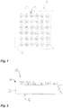
- a magnetic drape in accordance with an embodiment of the present disclosure is generally shown at 10.
- the magnetic drape 10 may be used to support instruments in surgery, treatment, dentistry, veterinary medicine, or in any other applications .
- the description below will generally refer to the use of the magnetic drape 10 to support instruments in surgery, but it will be understood that the magnetic drape 10 may be used in other applications.
- the term "drape" is used, but is not meant to be limitative.
- the drape is also know as a support mat, panel, etc.
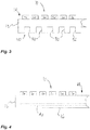
- the magnetic drape 10 has a drape body 12 with a top surface 14 and an undersurface 16.
- the drape body 12 is made of a semirigid or flexible material and may also be known as a pad, a drape, a carpet or the like. Materials that may be used include nonrestrictively various medical-grade polymers and elastomers such as silicone, rubbers, etc., depending on the specifications of use of the magnetic drape 10 (e.g., reusable and sterilizable, single-use drape).
- the drape body 12 may have any appropriate dimensions to lie on the body of a patient and support instruments thereon. It is also considered to mold a mesh (e.g., nylon mesh) into or on the drape body 12 to alter its structural integrity, or to provide tear-resistance to the drape body 12. However, the drape body 12 may be without such a nylon mesh.
- the drape body 12 When laid on the body of a patient, the drape body 12 conforms to the shape of the surface upon which it rests because of the flexible nature of its material.
- the drape body 12 is placed such that the undersurface 16 lies against the surface, whereas the top surface 14 is oriented upwardly.
- magnet units 20 are raised from a panel portion of the drape body 12 and therefore define the top surface 14 of the drape body 12, and are aligned in rows and columns.
- the magnet units 20 are fully encapsulated in the material of the drape body 12, whereby the top surface of the magnetic mat 10 is flat.
- the magnetic units 20 typically comprise a permanent magnet or permanent magnets that may be encapsulated, sandwiched or embedded in the material of the drape body 12, and include a supporting shielding cup.
- the magnet units 20 are illustrated as being circular in Figs. 1 and 2 , but may have any other appropriate shape, such as a rectangle, a strip or a bar as shown hereinafter. Moreover, the arrangement of components of the magnet units 20 is described in further details hereinafter.
- the presence of the permanent magnet units 20 in accordance with the embodiment of Figs. 1 and 2 will allow ferromagnetic instruments to be retained on the magnetic drape 10 when placed thereon by medical personnel or any technician.
- the magnetic forces of the magnet units 20 will pull the instruments to the magnetic drape 10.
- the magnets of the magnet units 20 may for instance be ferrite ceramic magnets (e.g., anisotropic), among numerous possibilities, and may adopt any appropriate shape (e.g., circular, rectangular).
- FIG. 2 there is illustrated the magnetic drape 10 of Fig. 1 . It is observed that the thickness of the drape body 12, namely between the top surface 14 and the undersurface 16, is nonnegligible. It is known that the flux density of a magnetic field reduces in value as a function of a distance from the magnets. There is provided in Fig. 18 a graph illustrating a general trend of the magnetic flux density of the magnetic field as a function of a distance to a surface. Accordingly, by having the drape body 12 provided with a selected thickness, it is possible to have a minimal magnetic flux density under the undersurface 16.
- the drape body 12 with undersurface 30.
- the undersurface 30 has a plurality of longitudinal channels 32.
- the longitudinal channels 32 are provided so as to increase the distance between the top surface 14 and the undersurface 30 of the drape body 12, in view of having a minimal magnetic flux density at the undersurface 30, while increasing the flexibility of the mat 10. As there is less material above the longitudinal channels 32, the drape body 12 is more flexible.
- Alternative shapes are considered as well, such as posts, ribs or the like.
- a shielding sheet 40 is provided in the drape body 12.
- the shielding sheet 40 may be laminated to the undersurface 16, or may simply be molded into the drape body 12.
- the shielding sheet 40 may be at any suitable location in the drape body 12.
- the drape body 12 may consist of different layers bonded to one another, for instance to encapsulate shielding material therebetween.
- multiple layers of shielding sheets may also be used and as an example, one layer can be laminated closer to the undersurface while another can be closer to the top surface.
- materials used for the shielding sheet 40 include sheets of ferromagnetic material or of foil.
- NanovateTM metal, numetal, powders, nano-materials, nano-metallurgical materials, such as nano-crystalline ferromagnetic cladding, among other possibilities.
- some embodiments of the NanovateTM platforms by Integran may be used.
- a mesh of shielding material e.g., NanovateTM
- NanovateTM may also be used.
- the magnet units 20 are constituted of one or more magnets supported on a shielding material which can be made of many materials such metal, numetal, powders, nano-materials, nano-metallurgical materials, such as nano-crystalline ferromagnetic cladding, among other possibilities.
- the various configurations are devised in order to produce a magnetic flux density of less than 0,001 tesla (10 Gauss) at a given distance below the undersurface 16 of the magnetic drape 10.
- the magnetic flux density is less than 0,001 tesla (10 Gauss) at a distance of 1/8 in from a bottom surface of the magnet units 20.
- the various configurations comprise magnets made of any appropriate material.
- ceramic 8 or polymeric-based materials are well suited as a material for magnets for the magnet unit 20, in view of the required flux density of the magnetic field under the magnetic drape 10.
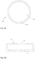
- the magnet unit 20 of Fig. 5A and 5B may be used in the magnetic drape 10 of Figs. 1 to 4 .
- the magnet unit 20 has at least one permanent magnet 60 encapsulated partially in a cup 62.
- the magnet 60 has at least a portion of its lateral surface and its bottom face within the cup 62, while the upper face is exposed.
- the cup 62 is made from a shielding material, such as mild steel (e.g., 1010 steel, 1018 steel), or any other appropriate material, whereby the magnetic flux density of the magnetic field is reduced away from the bottom face of the magnet 60.
- the bottom face of the magnet 60 (hidden in the cup 62) is oriented toward the undersurface 16 ( Fig. 1 ) of the magnetic drape 10.
- the cup 62 has a wall thickness ranging between 0.02-0.06 in (although other thicknesses are possible), with an outer diameter of 0.86 in, although other outer diameters are possible.
- the magnet 60 has a diameter ranging between 0.74-0.82 in, with the magnet 60 being snugly or force-fittingly received in the cup 62.
- a suitable height for the combination of the magnet 60 and cup 62 is 0.16 in, with the magnet 60 and cup 62 concurrently defining a top planar surface of the magnet unit 20.
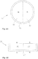
- a configuration of the magnet unit 20 is shown, using the specifications (e.g., dimensions and materials) set forth with the general arrangement of Figs. 5A and 5B .
- the cup 62 supports a bi-polar vertically magnetized magnet 60, with the magnet 60 exposing opposite poles on the top surface of the magnet unit 20, as illustrated by N and S.
- the magnet 60 has two sections, with each section arranged to have a first pole oriented toward the top surface of the magnet unit 20, and an opposite pole oriented toward the bottom surface of the magnet unit 20.
- the vertical direction is between the top surface 14 and the undersurface 16, but it not necessarily representative of the orientation in which the drape 10 will be used.
- the drape 10 may indeed be inclined, or even have a portion that is hanging vertically.
- the magnet 60 must have at least two sections of opposite poles exposed at the top surface of the magnet 60, which poles are produced by way of a magnetization process.
- the sections may be physically independent magnets in a same cup 62, with the independent magnets reproducing any one of the pole arrangements described herein.
- both embodiments of a single magnet with multiple sections, or multiple independent magnets in a same cup 62 will be referred to as sections of magnets, with the sections having a specific polarity arrangement to produce a magnetic flux density in accordance with the present invention.
- FIG. 7 another configuration of the magnet unit 20 is shown.
- the cup 62 supports the magnet 60, with the magnet 60 having three vertically magnetized sections of alternating opposite poles on the top surface (N-S-N) of the magnet unit 20, as illustrated by N and S.
- each of the sections of the magnet 60 is arranged to have a first pole oriented toward the top surface of the magnet unit 20, and an opposite pole oriented toward the bottom surface of the magnet unit 20.
- FIG. 8 another configuration of the magnet unit 20 is shown.
- the cup 62 supports the magnet 60 having four quarter-shaped vertically magnetized sections exposing a sequence of alternating opposite poles (N-S-N-S) on the top surface of the magnet unit 20, as illustrated by N and S.
- N-S-N-S alternating opposite poles
- each of the sections of the magnets 60 is arranged to have a first pole oriented toward the top surface of the magnet unit 20, and an opposite pole oriented toward the bottom surface of the magnet unit 20.
- FIG. 9 another configuration of the magnet unit 20 is shown.
- the cup 62 supports the magnet 60 with sixth-shaped vertically magnetized sections, with the sixth-shaped sections of the magnets 60 exposing a sequence of alternating opposite poles (N-S-N-S-N-S) on the top surface of the magnet unit 20, as illustrated by N and S.
- N-S-N-S-N-S alternating opposite poles
- each of the sections of the magnet 60 is arranged to have a first pole oriented toward the top surface of the magnet unit 20, and an opposite pole oriented toward the bottom surface of the magnet unit 20.
- FIG. 10 another configuration of the magnet unit 20 is shown.
- the cup 62 supports the magnet 60 with eighth-shaped vertically magnetized sections, with the eighth-shaped segments exposing a sequence of alternating opposite poles (N-S-N-S-N-S-N-S) on the top surface of the magnet unit 20, as illustrated by N and S.
- each of the segments 60 is arranged to have a first pole oriented toward the top surface of the magnet unit 20, and an opposite pole oriented toward the bottom surface of the magnet unit 20.
- FIG. 11A and 11B another configuration of the magnet unit 20 is shown.
- the cup 62 supports the magnet 60 having three magnetized segments in similar fashion to Fig. 7 .
- the configuration of Figs. 11A and 11B differs from the configuration of Fig. 7 , in that the magnets 60 are in a striped Halbach pattern.
- the central section of the magnets 60 is oriented sideways to have both north and south poles exposed from the top surface of the magnet unit 20.
- the north pole of the central section of the magnet 60 is adjacent to an exposed south pole of a lateral section of the magnets 60, whereas the south pole of the central section of magnet 60 is adjacent to an exposed north pole of the other lateral section of the magnet 60, as illustrated by N and S.
- the lateral sections of magnets 60 are arranged to have a first pole oriented toward the top surface of the magnet unit 20, and an opposite pole oriented toward the bottom surface of the magnet unit 20.
- the magnet unit 20 with a circular shape.
- the magnets 60 may be in a tenth-shaped sections configuration, or may even feature more magnet sections.
- the magnet unit 20 has a rectangular, strip or bar shape as opposed to a circular one.
- a general arrangement of the rectangular magnet unit 20 is shown in Figs. 12A and 12B .
- the magnet unit 20 of Fig. 12A and 12B may be used in the magnetic drape 10 of Figs. 1 to 4 .
- the magnet unit 20 has at least one permanent magnet 60' encapsulated partially in a cup 62'.
- the single magnet 60' must be magnetized so as to have at least two opposite poles in the top surface of the magnet 60'.
- the magnet 60' has at least a portion of its side surfaces and its bottom face within the cup 62', while the upper face is exposed.
- the cup 62' is made from a shielding material, such as mild steel (e.g., 1010 steel, 1018 steel), or any other appropriate shielding material, whereby the magnetic flux density of the magnetic field is reduced away from the bottom face of the magnet 60'.
- mild steel e.g., 1010 steel, 1018 steel
- the bottom face of the magnet 60' (hidden in the cup 62') is oriented toward the undersurface 16 ( Fig. 1 ) of the magnetic mat 10.
- the cup 62' has a wall thickness ranging between 0.02-0.06 in, with a length of 1.62 in and a width of 0.5 in, although other dimensions are possible.
- a suitable height for the combination of the magnet 60' and cup 62' is 0.1 in, although other dimensions are possible, with the magnet 60' and cup 62' concurrently defining a top planar surface of the magnet unit 20.
- a rectangular configuration of the magnet unit 20 is shown.
- the cup 62' supports a pair of elongated sections of the magnet 60', with the elongated sections of the magnet 60' exposing opposite poles on the top surface of the magnet unit 20, as illustrated by N and S.
- Each of the sections of the magnet 60' is arranged to have a first pole oriented toward the top surface of the magnet unit 20, and an opposite pole oriented toward the bottom surface of the magnet unit 20.
- FIG. 14A and 14B another configuration of the magnet unit 20 is shown.
- the cup 62' supports a pair of rectangular sections of the magnet 60', with the rectangular sections of the magnet 60' exposing opposite poles on the top surface of the magnet unit 20, as illustrated by N and S.
- each of the sections of the magnet 60' is arranged to have a first pole oriented toward the top surface of the magnet unit 20, and an opposite pole oriented toward the bottom surface of the magnet unit 20.
- FIG. 15 another configuration of the magnet unit 20 is shown.
- the cup 62' supports four square sections of the magnet 60', with the square sections of the magnet 60' exposing alternating opposite poles (N-S-N-S) on the top surface of the magnet unit 20, as illustrated by N and S.
- Each of the sections of the magnet 60' is arranged to have a first pole oriented toward the top surface of the magnet unit 20, and an opposite pole oriented toward the bottom surface of the magnet unit 20.
- the magnet unit 20 of Figs. 16 and 17 may be used in the magnetic mat 10 of Figs. 1 to 4 .
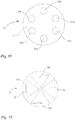
- the magnet unit 20 comprises a plurality of smaller permanents magnets 70N and 70S, with the affixed N indicating a North polarity while the affixed S indicates a South polarity.
- the magnets 70 are each received in a respective cavity in a metallic cup 72.
- the magnets 70 each have their lateral portion and their bottom face within a respective cavity of the cup 72, while the upper face is exposed.
- the metallic cup 72 is made from a shielding material, such as 1018 steel, or any other appropriate material, whereby the magnitude of the magnetic field is reduced away from the bottom face of the magnets 70.
- a shielding material such as 1018 steel, or any other appropriate material, whereby the magnitude of the magnetic field is reduced away from the bottom face of the magnets 70.
- the magnet unit 20 comprises six magnets 70, although a magnet unit 20 may comprise more or less permanent magnets. Moreover, the magnets 70 are shown in an alternating polarity about the magnet unit 20. The magnets 70 are also arranged with diametrically opposed polarities, although other arrangements may also be suitable.
- the magnets 70 are illustrated as being circular, but may have other geometries. For instance, a plurality of pie-shaped magnets 70 may share one common circular cavity in the cup 72, as illustrated in Fig. 17 .
- the permanent magnets 60, 60' and 70 are made of any suitable magnetic material.
- One type of permanent magnet that may be used in the magnetic drape 10 is a standard or commercial ferrite magnets, although samarium-cobalt magnets (model 26002, Grade 24, with 2% samarium and 17% cobalt from Armstrong Magnetics Inc.) may also be used.
- samarium-cobalt magnets model 26002, Grade 24, with 2% samarium and 17% cobalt from Armstrong Magnetics Inc.
- the cups 62, 62' and 72 they may be machined, cast, molded, etc.
- Figs. 1 to 17 there may be provided on the undersurface 16 of the magnetic drape 10 a logo, an icon, instructions or the like, to indicate that the mat 10 is upside down.
- the mat 10 should be used with the magnet units 20 facing upwardly.
- These instructions may also be on the top surface 14 to indicate that the mat 10 is correctly installed. In an embodiment, these instructions are printed directly on the surfaces of the magnetic drape 10.
- a graph illustrates a relation between a distance and a magnetic flux density.
- an increase in distance from the magnet units 20 results in a decrease in the magnetic flux density.
- the drape 10 may have an increased thickness under the magnet units 20 so as to ensure that the magnetic flux density is below a predetermined value.
- the afore-described embodiments allow the magnetic drape 10 to maintain a magnetic flux density of less than 0,001 tesla (10 Gauss) at a distance of 1/8 in below the bottom surface of the magnet units 20. If a lower magnetic flux density is required, the thickness of the panel of the drape body 12 may be increased.
- inventions may be for single-use magnetic drapes or for sterilizable magnetic drapes that will be reused.
- the embodiments described above may be used individually, or in combination where applicable.
Landscapes
- Health & Medical Sciences (AREA)
- Life Sciences & Earth Sciences (AREA)
- Veterinary Medicine (AREA)
- Engineering & Computer Science (AREA)
- Surgery (AREA)
- Public Health (AREA)
- Animal Behavior & Ethology (AREA)
- General Health & Medical Sciences (AREA)
- Electromagnetism (AREA)
- Power Engineering (AREA)
- Physics & Mathematics (AREA)
- Heart & Thoracic Surgery (AREA)
- Biomedical Technology (AREA)
- Medical Informatics (AREA)
- Molecular Biology (AREA)
- Epidemiology (AREA)
- Dentistry (AREA)
- Oral & Maxillofacial Surgery (AREA)
- Wood Science & Technology (AREA)
- Zoology (AREA)
- Magnetic Treatment Devices (AREA)
Claims (15)
- Magnetisches Tuch (10) mit:einem Tuchkörper (12), der aus einem flexiblen Material besteht, wobei der Tuchkörper (12) einen Bahnabschnitt aufweist, der eine Unterseite (16, 30), die eingerichtet ist, auf einen unebenen Körper gelegt zu werden, und eine Oberseite (14) und eine gegebene Dicke zwischen der Unterseite (16, 30) und der Oberseite (14) aufweist; undmehreren Magneteinheiten (20) innerhalb des flexiblen Materials des Tuchkörpers (12), wobei jede Magneteinheit (20) ein Abschirmungsmaterial in der Form eines Napfes (62, 62', 72), der so ausgerichtet ist, dass er eine Bodenwand aufweist, die zur Unterseite (16, 30) des Tuchkörpers (12) weist, und mindestens einen Magneten (60, 60', 70) aufweist, der mindestens teilweise in den Napf (62, 62', 72) aufgenommen ist,dadurch gekennzeichnet, dass der mindestens eine Magnet (60, 60', 70) mindestens zwei Abschnitte aufweist, die so angeordnet sind, dass sie auf einer Oberseite (14) des magnetischen Tuchs (12) eine entgegengesetzte Polarität freilegen, wobei jeder Abschnitt entgegengesetzte Polaritäten aufweist, die vertikal ausgerichtet sind.
- Magnetisches Tuch (10) nach Anspruch 1,
wobei die Magneteinheiten (20) jeweils eine Kreisform und/oder eine rechteckige Form aufweisen. - Magnetisches Tuch (10) nach Anspruch 2,
wobei die Näpfe (62) jeweils eine Kreisform aufweisen und ferner zwei Abschnitte der Magnete (60) in jedem Napf (62) aufweisen, wobei jeder Abschnitt eine Halbkreisform aufweist. - Magnetisches Tuch (10) nach Anspruch 2,
wobei die Näpfe (62) jeweils eine Kreisform aufweisen und ferner mindestens vier Abschnitte der Magnete (60) in jedem Napf (62) aufweisen, wobei jeder Abschnitt eine Tortenform aufweist, wobei die Abschnitte eine N-S-Abfolge von entgegengesetzten Polen in der Oberseite der Magneteinheit (20) freilegen. - Magnetisches Tuch (10) nach Anspruch 2,
wobei die Näpfe (62) jeweils eine Kreisform aufweisen und wobei ferner der mindestens eine Magnet (60) drei Abschnitte in jedem Napf (62) aufweist, wobei jeder Abschnitt eine längliche Form aufweist, wobei die Abschnitte so nebeneinander angeordnet sind, dass sie eine Kreisform definieren, wobei die Magnete (60) eine Abfolge von entgegengesetzten Polen in der Oberseite der Magneteinheit (20) freilegen. - Magnetisches Tuch (10) nach Anspruch 2,
wobei die Näpfe (62) jeweils eine Kreisform aufweisen, und wobei ferner der mindestens einen Magnet (60) drei Abschnitte in jedem Napf (62) aufweist, wobei jeder Abschnitt eine längliche Form aufweist, wobei die Abschnitte so nebeneinander angeordnet sind, dass sie eine Kreisform definieren, wobei laterale Abschnitte entgegengesetzte Pole in der Oberseite (14) der Magneteinheit (20) freilegen, und wobei ein mittlerer Abschnitt relativ zu den lateralen Abschnitten so ausgerichtet ist, dass ein Halbach-Effekt erzeugt wird. - Magnetisches Tuch (10) nach Anspruch 2,
wobei die Näpfe (62') jeweils eine rechteckige Form aufweisen, und wobei der mindestens eine Magnet (60') zwei Abschnitte in jedem Napf (62') aufweist, wobei jeder Abschnitt eine längliche Form aufweist, wobei die Abschnitte so nebeneinander angeordnet sind, dass sie eine rechteckige Form definieren. - Magnetisches Tuch (10) nach Anspruch 2,
wobei die Näpfe (62') jeweils eine rechteckige Form aufweisen, und wobei der mindestens eine Magnet (60') mindestens zwei Abschnitte in jedem Napf (62') aufweist, wobei jeder Abschnitt eine quadratische oder rechteckige Form aufweist, wobei die Abschnitte so nebeneinander angeordnet sind, dass sie eine rechteckige Form definieren. - Magnetisches Tuch (10) nach Anspruch 2,
wobei die Näpfe (72) jeweils eine Kreisform mit mindestens zwei Hohlräumen aufweisen und ferner einen der Abschnitte des Magnets (70) in jedem Hohlraum der Näpfe (72) aufweisen, wobei die Hohlräume eine Kreisform oder eine dreieckige Form aufweisen. - Magnetisches Tuch (10) nach einem der Ansprüche 1 bis 9, das ferner unter den mehreren der Magneteinheiten (20) ein Abschirmungsmittel aufweist, das mit dem Tuchkörper (12) verbunden oder in ihn eingebaut ist.
- Magnetisches Tuch (10) nach Anspruch 10,
wobei das Abschirmungsmittel eine Abschirmungsfolie (40) und/oder ein Abschirmungsgewebe und/oder ein Abschirmungsmaterial und/oder Abschirmungsteilchen aufweist. - Magnetisches Tuch (10) nach einem der Ansprüche 1 bis 11, das ferner eine fluoreszierende und/oder phosphoreszierende Beschichtung oder Additiv auf der Oberseite (14) des Tuchkörpers (12) aufweist.
- Magnetisches Tuch (10) nach einem der Ansprüche 1 bis 12, wobei die Magneteinheiten (20) nach oben aus der Oberseite (14) des Bahnabschnitts des Tuchkörpers (12) vorstehen.
- Magnetisches Tuch (10) nach Anspruch 13,
wobei die gegebene Dicke des Bahnabschnitts mindestens 1/8 Zoll beträgt, so dass eine magnetische Flussdichte an der Unterseite des Tuchkörpers kleiner als 0,001 Tesla (10 Gauß) ist. - Magnetisches Tuch (10) nach Anspruch 13,
wobei die gegebene Dicke des Bahnabschnitts so bemessen ist, dass die Magneteinheiten (20) in einem Abstand von mindestens 1/8 Zoll von einer elektronischen Vorrichtung in einem Patienten gehalten werden, wenn das magnetische Tuch (10) auf den Patienten gelegt wird, so dass eine magnetische Flussdichte an der elektronischen Vorrichtung kleiner als 0,001 Tesla (10 Gauß) ist.
Applications Claiming Priority (3)
| Application Number | Priority Date | Filing Date | Title |
|---|---|---|---|
| US35772210P | 2010-06-23 | 2010-06-23 | |
| US201161434986P | 2011-01-21 | 2011-01-21 | |
| PCT/CA2011/050387 WO2011160236A1 (en) | 2010-06-23 | 2011-06-23 | Magnetic interference reducing surgical drape |
Publications (3)
| Publication Number | Publication Date |
|---|---|
| EP2584993A1 EP2584993A1 (de) | 2013-05-01 |
| EP2584993A4 EP2584993A4 (de) | 2015-04-08 |
| EP2584993B1 true EP2584993B1 (de) | 2019-03-27 |
Family
ID=45370794
Family Applications (1)
| Application Number | Title | Priority Date | Filing Date |
|---|---|---|---|
| EP11797447.7A Active EP2584993B1 (de) | 2010-06-23 | 2011-06-23 | Op-abdecktuch mit reduzierung der magnetischen interferenz |
Country Status (4)
| Country | Link |
|---|---|
| US (1) | US9232976B2 (de) |
| EP (1) | EP2584993B1 (de) |
| CA (1) | CA2803194C (de) |
| WO (1) | WO2011160236A1 (de) |
Families Citing this family (10)
| Publication number | Priority date | Publication date | Assignee | Title |
|---|---|---|---|---|
| US20140299739A1 (en) * | 2013-04-08 | 2014-10-09 | Bradeaux LLC | Personal Magnetic Surgical Instrument System |
| KR102510796B1 (ko) | 2014-03-17 | 2023-03-17 | 인튜어티브 서지컬 오퍼레이션즈 인코포레이티드 | 수술용 드레이프와 수술용 드레이프를 포함하는 시스템 및 부착 센서 |
| WO2018013300A1 (en) | 2016-07-14 | 2018-01-18 | Intuitive Surgical Operations, Inc. | Mechanism for managing and retaining a surgical drape |
| ES3025191T3 (en) | 2017-04-27 | 2025-06-06 | Magswitch Tech Worldwide Pty Ltd | Magnetic coupling device with at least one of a sensor arrangement and a degauss capability |
| US20250065460A1 (en) * | 2017-04-27 | 2025-02-27 | Magswitch Technology, Inc. | Magnetic coupling device with at least one of a sensor arrangement and a degauss capability |
| US10903030B2 (en) | 2017-04-27 | 2021-01-26 | Magswitch Technology Worldwide Pty Ltd. | Variable field magnetic couplers and methods for engaging a ferromagnetic workpiece |
| CN118752281A (zh) | 2017-04-27 | 2024-10-11 | 磁转换技术股份有限公司 | 具有至少一个传感器布置和消磁能力的磁耦合装置 |
| CN115331911B (zh) | 2017-06-08 | 2025-07-22 | 磁转换技术股份有限公司 | 用于与铁磁工件磁耦接的磁耦接装置 |
| WO2019030087A1 (en) * | 2017-08-09 | 2019-02-14 | Basf Se | HERBICIDE MIXTURES COMPRISING L-GLUFOSINATE OR SALT THEREOF AND AT LEAST ONE INHIBITOR OF LIPID BIOSYNTHESIS |
| EP4341049A4 (de) | 2021-06-11 | 2025-03-12 | Magswitch Technology, Inc. | Werkzeug oder vorrichtung mit einstellbarem armende |
Family Cites Families (38)
| Publication number | Priority date | Publication date | Assignee | Title |
|---|---|---|---|---|
| US3483494A (en) | 1965-09-03 | 1969-12-09 | Surgitool Inc | Magnetic surgical drape |
| US3727658A (en) | 1971-09-22 | 1973-04-17 | Instranetics Inc | Receiver for surgical implements |
| US4185262A (en) * | 1977-08-01 | 1980-01-22 | Matsushita Electric Industrial Co., Ltd. | Magnet device |
| US4373629A (en) | 1981-06-09 | 1983-02-15 | Akzona Incorporated | Used surgical sharps container with re-usable magnetic base |
| JPS5898904A (ja) * | 1981-12-09 | 1983-06-13 | Dai Ichi Seiko Co Ltd | 永久磁石成形品 |
| US4524767A (en) | 1982-07-06 | 1985-06-25 | Glassman Jacob A | Surgical drapes |
| US4944311A (en) * | 1988-03-09 | 1990-07-31 | Jodel Medical Products, Inc. | Surgical instrument retainer |
| US5195538A (en) * | 1989-02-17 | 1993-03-23 | Devon Industries, Inc. | Surgical instrument tray |
| US5277692A (en) | 1992-01-21 | 1994-01-11 | Vincent Ardizzone | Flexible magnetic pad with multi-directional constantly alternating polarity zones |
| US6023165A (en) * | 1992-09-28 | 2000-02-08 | Fonar Corporation | Nuclear magnetic resonance apparatus and methods of use and facilities for incorporating the same |
| US5578359A (en) * | 1994-11-29 | 1996-11-26 | Hewlett Packard Company | Magnetic shielding garment for electro-biologic measurements |
| US20020088515A1 (en) | 1996-03-01 | 2002-07-11 | Aust Karl T. | Thermo-mechanical treated lead and lead alloys especially for current collectors and connectors in lead-acid batteries |
| US6342110B1 (en) | 1996-03-01 | 2002-01-29 | Integran Technologies Inc. | Lead and lead alloys with enhanced creep and/or intergranular corrosion resistance, especially for lead-acid batteries and electrodes therefor |
| US20040112486A1 (en) | 1996-03-01 | 2004-06-17 | Aust Karl T. | Thermo-mechanical treated lead and lead alloys especially for current collectors and connectors in lead-acid batteries |
| GB9903647D0 (en) | 1999-02-18 | 1999-04-07 | Technovent Ltd | Mat |
| US6344097B1 (en) | 2000-05-26 | 2002-02-05 | Integran Technologies Inc. | Surface treatment of austenitic Ni-Fe-Cr-based alloys for improved resistance to intergranular-corrosion and-cracking |
| US20030234181A1 (en) | 2002-06-25 | 2003-12-25 | Gino Palumbo | Process for in-situ electroforming a structural layer of metallic material to an outside wall of a metal tube |
| US20050205425A1 (en) | 2002-06-25 | 2005-09-22 | Integran Technologies | Process for electroplating metallic and metall matrix composite foils, coatings and microcomponents |
| US6868854B2 (en) | 2003-05-27 | 2005-03-22 | Frieder K. Kempe | Method and article for treatment of fibromyalgia |
| US7320832B2 (en) | 2004-12-17 | 2008-01-22 | Integran Technologies Inc. | Fine-grained metallic coatings having the coefficient of thermal expansion matched to the one of the substrate |
| US7354354B2 (en) | 2004-12-17 | 2008-04-08 | Integran Technologies Inc. | Article comprising a fine-grained metallic material and a polymeric material |
| US7387578B2 (en) | 2004-12-17 | 2008-06-17 | Integran Technologies Inc. | Strong, lightweight article containing a fine-grained metallic layer |
| US8273117B2 (en) | 2005-06-22 | 2012-09-25 | Integran Technologies Inc. | Low texture, quasi-isotropic metallic stent |
| EP1941521A4 (de) * | 2005-09-26 | 2011-06-15 | Magswitch Technology Worldwide Pty Ltd | Magnet-arrays |
| WO2008141137A2 (en) | 2007-05-10 | 2008-11-20 | Envisionier Medical Technologies Llc | Surgical drape with configurable channel regions |
| BRPI0816497A8 (pt) | 2007-10-04 | 2017-09-26 | K Robertson Clive | Membro estrutural para um dispositivo eletrônico portátil e dispositivo eletrônico portátil |
| WO2009045416A1 (en) | 2007-10-04 | 2009-04-09 | E.I. Du Pont De Nemours And Company | Vehicular electrical and electronic housings |
| EP2222897B1 (de) | 2007-12-18 | 2017-02-08 | Integran Technologies Inc. | Verfahren zur herstellung polykristalliner strukturen mit verbesserten mechanischen und physikalischen eigenschaften |
| US9005420B2 (en) | 2007-12-20 | 2015-04-14 | Integran Technologies Inc. | Variable property electrodepositing of metallic structures |
| US8816806B2 (en) | 2008-04-03 | 2014-08-26 | Tait Towers Manufacturing, LLC | Magnetically coupled device |
| US20090267717A1 (en) * | 2008-04-24 | 2009-10-29 | Baskett Michael D | Magnetic Mat for Holding Surgical Instruments |
| US9119906B2 (en) | 2008-09-24 | 2015-09-01 | Integran Technologies, Inc. | In-vivo biodegradable medical implant |
| US8309233B2 (en) | 2009-06-02 | 2012-11-13 | Integran Technologies, Inc. | Electrodeposited metallic-materials comprising cobalt on ferrous-alloy substrates |
| US8906515B2 (en) | 2009-06-02 | 2014-12-09 | Integran Technologies, Inc. | Metal-clad polymer article |
| US8367217B2 (en) | 2009-06-02 | 2013-02-05 | Integran Technologies, Inc. | Electrodeposited metallic-materials comprising cobalt on iron-alloy substrates with enhanced fatigue performance |
| US8545994B2 (en) | 2009-06-02 | 2013-10-01 | Integran Technologies Inc. | Electrodeposited metallic materials comprising cobalt |
| US8247050B2 (en) | 2009-06-02 | 2012-08-21 | Integran Technologies, Inc. | Metal-coated polymer article of high durability and vacuum and/or pressure integrity |
| US8394507B2 (en) | 2009-06-02 | 2013-03-12 | Integran Technologies, Inc. | Metal-clad polymer article |
-
2011
- 2011-06-23 WO PCT/CA2011/050387 patent/WO2011160236A1/en not_active Ceased
- 2011-06-23 US US13/805,448 patent/US9232976B2/en active Active
- 2011-06-23 CA CA2803194A patent/CA2803194C/en active Active
- 2011-06-23 EP EP11797447.7A patent/EP2584993B1/de active Active
Non-Patent Citations (1)
| Title |
|---|
| None * |
Also Published As
| Publication number | Publication date |
|---|---|
| US20130199544A1 (en) | 2013-08-08 |
| WO2011160236A1 (en) | 2011-12-29 |
| CA2803194C (en) | 2018-10-16 |
| CA2803194A1 (en) | 2011-12-29 |
| EP2584993A4 (de) | 2015-04-08 |
| EP2584993A1 (de) | 2013-05-01 |
| US9232976B2 (en) | 2016-01-12 |
Similar Documents
| Publication | Publication Date | Title |
|---|---|---|
| US9232976B2 (en) | Magnetic interference reducing surgical drape | |
| CN103705310B (zh) | 用于跟踪原位手术应用的磁场观察膜 | |
| US20130331638A1 (en) | Self-adhesive tet coil holder with alignment feature | |
| Sarwar et al. | Magnetic injection of nanoparticles into rat inner ears at a human head working distance | |
| CN103998088A (zh) | 患者界面装置 | |
| US11253657B2 (en) | Systems, methods and devices for subcutaneous target location | |
| US20180056084A1 (en) | Skull implanted magnet assembly for brain stimulation | |
| US20210338098A1 (en) | Permanent magnet rotor for medical device tracking | |
| US20150000676A1 (en) | Surgical Drape and Attachment Mechanism | |
| WO2000048526A1 (en) | Mat for retaining surgical instruments | |
| US20250174370A1 (en) | Radiation shielding devices, systems, and methods | |
| US20160015992A1 (en) | Icd/vad defibrillator electromagnet | |
| US11628015B1 (en) | Systems and methods for performing a surgical procedure | |
| US20220249036A1 (en) | Radiation shielding devices, systems, and methods | |
| CN219148776U (zh) | 磁性完全植入式静脉输液港 | |
| Raguž et al. | Frameless stereotactic brain biopsy and external ventricular drainage placement using the RONNA G4 system | |
| US8944068B2 (en) | Drape | |
| CN204972178U (zh) | 风湿按摩装置 | |
| JP5491654B2 (ja) | 付着型磁石針 | |
| CN211301147U (zh) | 一种中医针灸温针醒针消毒装置 | |
| CN222917566U (zh) | 用于收纳手术缝针的磁吸针盘 | |
| CN106730373B (zh) | 钴锆钼合金标 | |
| WO2012151042A1 (en) | Adhesive magnetic system | |
| CN108992781A (zh) | 一种永磁体槽的存放及调整网点 | |
| CN204501875U (zh) | 一种一次性无菌静推盒 |
Legal Events
| Date | Code | Title | Description |
|---|---|---|---|
| PUAI | Public reference made under article 153(3) epc to a published international application that has entered the european phase |
Free format text: ORIGINAL CODE: 0009012 |
|
| 17P | Request for examination filed |
Effective date: 20130121 |
|
| AK | Designated contracting states |
Kind code of ref document: A1 Designated state(s): AL AT BE BG CH CY CZ DE DK EE ES FI FR GB GR HR HU IE IS IT LI LT LU LV MC MK MT NL NO PL PT RO RS SE SI SK SM TR |
|
| DAX | Request for extension of the european patent (deleted) | ||
| RA4 | Supplementary search report drawn up and despatched (corrected) |
Effective date: 20150305 |
|
| RIC1 | Information provided on ipc code assigned before grant |
Ipc: A61B 19/10 20060101AFI20150227BHEP Ipc: A61B 19/08 20060101ALN20150227BHEP Ipc: H01F 7/02 20060101ALI20150227BHEP |
|
| REG | Reference to a national code |
Ref country code: DE Ref legal event code: R079 Ref document number: 602011057576 Country of ref document: DE Free format text: PREVIOUS MAIN CLASS: A61B0019100000 Ipc: A61B0046230000 |
|
| GRAP | Despatch of communication of intention to grant a patent |
Free format text: ORIGINAL CODE: EPIDOSNIGR1 |
|
| STAA | Information on the status of an ep patent application or granted ep patent |
Free format text: STATUS: GRANT OF PATENT IS INTENDED |
|
| RIC1 | Information provided on ipc code assigned before grant |
Ipc: A61B 46/00 20160101ALN20180913BHEP Ipc: A61B 46/23 20160101AFI20180913BHEP Ipc: H01F 7/02 20060101ALI20180913BHEP |
|
| RIC1 | Information provided on ipc code assigned before grant |
Ipc: A61B 46/23 20160101AFI20180927BHEP Ipc: A61B 46/00 20160101ALN20180927BHEP Ipc: H01F 7/02 20060101ALI20180927BHEP |
|
| INTG | Intention to grant announced |
Effective date: 20181012 |
|
| GRAS | Grant fee paid |
Free format text: ORIGINAL CODE: EPIDOSNIGR3 |
|
| GRAA | (expected) grant |
Free format text: ORIGINAL CODE: 0009210 |
|
| STAA | Information on the status of an ep patent application or granted ep patent |
Free format text: STATUS: THE PATENT HAS BEEN GRANTED |
|
| AK | Designated contracting states |
Kind code of ref document: B1 Designated state(s): AL AT BE BG CH CY CZ DE DK EE ES FI FR GB GR HR HU IE IS IT LI LT LU LV MC MK MT NL NO PL PT RO RS SE SI SK SM TR |
|
| REG | Reference to a national code |
Ref country code: GB Ref legal event code: FG4D |
|
| REG | Reference to a national code |
Ref country code: CH Ref legal event code: EP |
|
| REG | Reference to a national code |
Ref country code: AT Ref legal event code: REF Ref document number: 1112098 Country of ref document: AT Kind code of ref document: T Effective date: 20190415 |
|
| REG | Reference to a national code |
Ref country code: IE Ref legal event code: FG4D |
|
| REG | Reference to a national code |
Ref country code: DE Ref legal event code: R096 Ref document number: 602011057576 Country of ref document: DE |
|
| PG25 | Lapsed in a contracting state [announced via postgrant information from national office to epo] |
Ref country code: LT Free format text: LAPSE BECAUSE OF FAILURE TO SUBMIT A TRANSLATION OF THE DESCRIPTION OR TO PAY THE FEE WITHIN THE PRESCRIBED TIME-LIMIT Effective date: 20190327 Ref country code: SE Free format text: LAPSE BECAUSE OF FAILURE TO SUBMIT A TRANSLATION OF THE DESCRIPTION OR TO PAY THE FEE WITHIN THE PRESCRIBED TIME-LIMIT Effective date: 20190327 Ref country code: NO Free format text: LAPSE BECAUSE OF FAILURE TO SUBMIT A TRANSLATION OF THE DESCRIPTION OR TO PAY THE FEE WITHIN THE PRESCRIBED TIME-LIMIT Effective date: 20190627 Ref country code: FI Free format text: LAPSE BECAUSE OF FAILURE TO SUBMIT A TRANSLATION OF THE DESCRIPTION OR TO PAY THE FEE WITHIN THE PRESCRIBED TIME-LIMIT Effective date: 20190327 |
|
| REG | Reference to a national code |
Ref country code: NL Ref legal event code: MP Effective date: 20190327 |
|
| PG25 | Lapsed in a contracting state [announced via postgrant information from national office to epo] |
Ref country code: LV Free format text: LAPSE BECAUSE OF FAILURE TO SUBMIT A TRANSLATION OF THE DESCRIPTION OR TO PAY THE FEE WITHIN THE PRESCRIBED TIME-LIMIT Effective date: 20190327 Ref country code: GR Free format text: LAPSE BECAUSE OF FAILURE TO SUBMIT A TRANSLATION OF THE DESCRIPTION OR TO PAY THE FEE WITHIN THE PRESCRIBED TIME-LIMIT Effective date: 20190628 Ref country code: HR Free format text: LAPSE BECAUSE OF FAILURE TO SUBMIT A TRANSLATION OF THE DESCRIPTION OR TO PAY THE FEE WITHIN THE PRESCRIBED TIME-LIMIT Effective date: 20190327 Ref country code: NL Free format text: LAPSE BECAUSE OF FAILURE TO SUBMIT A TRANSLATION OF THE DESCRIPTION OR TO PAY THE FEE WITHIN THE PRESCRIBED TIME-LIMIT Effective date: 20190327 Ref country code: RS Free format text: LAPSE BECAUSE OF FAILURE TO SUBMIT A TRANSLATION OF THE DESCRIPTION OR TO PAY THE FEE WITHIN THE PRESCRIBED TIME-LIMIT Effective date: 20190327 Ref country code: BG Free format text: LAPSE BECAUSE OF FAILURE TO SUBMIT A TRANSLATION OF THE DESCRIPTION OR TO PAY THE FEE WITHIN THE PRESCRIBED TIME-LIMIT Effective date: 20190627 |
|
| REG | Reference to a national code |
Ref country code: AT Ref legal event code: MK05 Ref document number: 1112098 Country of ref document: AT Kind code of ref document: T Effective date: 20190327 |
|
| PG25 | Lapsed in a contracting state [announced via postgrant information from national office to epo] |
Ref country code: AL Free format text: LAPSE BECAUSE OF FAILURE TO SUBMIT A TRANSLATION OF THE DESCRIPTION OR TO PAY THE FEE WITHIN THE PRESCRIBED TIME-LIMIT Effective date: 20190327 Ref country code: ES Free format text: LAPSE BECAUSE OF FAILURE TO SUBMIT A TRANSLATION OF THE DESCRIPTION OR TO PAY THE FEE WITHIN THE PRESCRIBED TIME-LIMIT Effective date: 20190327 Ref country code: CZ Free format text: LAPSE BECAUSE OF FAILURE TO SUBMIT A TRANSLATION OF THE DESCRIPTION OR TO PAY THE FEE WITHIN THE PRESCRIBED TIME-LIMIT Effective date: 20190327 Ref country code: RO Free format text: LAPSE BECAUSE OF FAILURE TO SUBMIT A TRANSLATION OF THE DESCRIPTION OR TO PAY THE FEE WITHIN THE PRESCRIBED TIME-LIMIT Effective date: 20190327 Ref country code: EE Free format text: LAPSE BECAUSE OF FAILURE TO SUBMIT A TRANSLATION OF THE DESCRIPTION OR TO PAY THE FEE WITHIN THE PRESCRIBED TIME-LIMIT Effective date: 20190327 Ref country code: IT Free format text: LAPSE BECAUSE OF FAILURE TO SUBMIT A TRANSLATION OF THE DESCRIPTION OR TO PAY THE FEE WITHIN THE PRESCRIBED TIME-LIMIT Effective date: 20190327 Ref country code: PT Free format text: LAPSE BECAUSE OF FAILURE TO SUBMIT A TRANSLATION OF THE DESCRIPTION OR TO PAY THE FEE WITHIN THE PRESCRIBED TIME-LIMIT Effective date: 20190727 Ref country code: SK Free format text: LAPSE BECAUSE OF FAILURE TO SUBMIT A TRANSLATION OF THE DESCRIPTION OR TO PAY THE FEE WITHIN THE PRESCRIBED TIME-LIMIT Effective date: 20190327 |
|
| PG25 | Lapsed in a contracting state [announced via postgrant information from national office to epo] |
Ref country code: PL Free format text: LAPSE BECAUSE OF FAILURE TO SUBMIT A TRANSLATION OF THE DESCRIPTION OR TO PAY THE FEE WITHIN THE PRESCRIBED TIME-LIMIT Effective date: 20190327 Ref country code: SM Free format text: LAPSE BECAUSE OF FAILURE TO SUBMIT A TRANSLATION OF THE DESCRIPTION OR TO PAY THE FEE WITHIN THE PRESCRIBED TIME-LIMIT Effective date: 20190327 |
|
| PG25 | Lapsed in a contracting state [announced via postgrant information from national office to epo] |
Ref country code: AT Free format text: LAPSE BECAUSE OF FAILURE TO SUBMIT A TRANSLATION OF THE DESCRIPTION OR TO PAY THE FEE WITHIN THE PRESCRIBED TIME-LIMIT Effective date: 20190327 Ref country code: IS Free format text: LAPSE BECAUSE OF FAILURE TO SUBMIT A TRANSLATION OF THE DESCRIPTION OR TO PAY THE FEE WITHIN THE PRESCRIBED TIME-LIMIT Effective date: 20190727 |
|
| REG | Reference to a national code |
Ref country code: DE Ref legal event code: R097 Ref document number: 602011057576 Country of ref document: DE |
|
| PG25 | Lapsed in a contracting state [announced via postgrant information from national office to epo] |
Ref country code: MC Free format text: LAPSE BECAUSE OF FAILURE TO SUBMIT A TRANSLATION OF THE DESCRIPTION OR TO PAY THE FEE WITHIN THE PRESCRIBED TIME-LIMIT Effective date: 20190327 Ref country code: DK Free format text: LAPSE BECAUSE OF FAILURE TO SUBMIT A TRANSLATION OF THE DESCRIPTION OR TO PAY THE FEE WITHIN THE PRESCRIBED TIME-LIMIT Effective date: 20190327 |
|
| REG | Reference to a national code |
Ref country code: CH Ref legal event code: PL |
|
| PLBE | No opposition filed within time limit |
Free format text: ORIGINAL CODE: 0009261 |
|
| STAA | Information on the status of an ep patent application or granted ep patent |
Free format text: STATUS: NO OPPOSITION FILED WITHIN TIME LIMIT |
|
| PG25 | Lapsed in a contracting state [announced via postgrant information from national office to epo] |
Ref country code: SI Free format text: LAPSE BECAUSE OF FAILURE TO SUBMIT A TRANSLATION OF THE DESCRIPTION OR TO PAY THE FEE WITHIN THE PRESCRIBED TIME-LIMIT Effective date: 20190327 |
|
| 26N | No opposition filed |
Effective date: 20200103 |
|
| REG | Reference to a national code |
Ref country code: BE Ref legal event code: MM Effective date: 20190630 |
|
| PG25 | Lapsed in a contracting state [announced via postgrant information from national office to epo] |
Ref country code: TR Free format text: LAPSE BECAUSE OF FAILURE TO SUBMIT A TRANSLATION OF THE DESCRIPTION OR TO PAY THE FEE WITHIN THE PRESCRIBED TIME-LIMIT Effective date: 20190327 |
|
| PG25 | Lapsed in a contracting state [announced via postgrant information from national office to epo] |
Ref country code: IE Free format text: LAPSE BECAUSE OF NON-PAYMENT OF DUE FEES Effective date: 20190623 |
|
| PG25 | Lapsed in a contracting state [announced via postgrant information from national office to epo] |
Ref country code: BE Free format text: LAPSE BECAUSE OF NON-PAYMENT OF DUE FEES Effective date: 20190630 Ref country code: LU Free format text: LAPSE BECAUSE OF NON-PAYMENT OF DUE FEES Effective date: 20190623 Ref country code: CH Free format text: LAPSE BECAUSE OF NON-PAYMENT OF DUE FEES Effective date: 20190630 Ref country code: LI Free format text: LAPSE BECAUSE OF NON-PAYMENT OF DUE FEES Effective date: 20190630 |
|
| PG25 | Lapsed in a contracting state [announced via postgrant information from national office to epo] |
Ref country code: CY Free format text: LAPSE BECAUSE OF FAILURE TO SUBMIT A TRANSLATION OF THE DESCRIPTION OR TO PAY THE FEE WITHIN THE PRESCRIBED TIME-LIMIT Effective date: 20190327 |
|
| PG25 | Lapsed in a contracting state [announced via postgrant information from national office to epo] |
Ref country code: MT Free format text: LAPSE BECAUSE OF FAILURE TO SUBMIT A TRANSLATION OF THE DESCRIPTION OR TO PAY THE FEE WITHIN THE PRESCRIBED TIME-LIMIT Effective date: 20190327 Ref country code: HU Free format text: LAPSE BECAUSE OF FAILURE TO SUBMIT A TRANSLATION OF THE DESCRIPTION OR TO PAY THE FEE WITHIN THE PRESCRIBED TIME-LIMIT; INVALID AB INITIO Effective date: 20110623 |
|
| PG25 | Lapsed in a contracting state [announced via postgrant information from national office to epo] |
Ref country code: MK Free format text: LAPSE BECAUSE OF FAILURE TO SUBMIT A TRANSLATION OF THE DESCRIPTION OR TO PAY THE FEE WITHIN THE PRESCRIBED TIME-LIMIT Effective date: 20190327 |
|
| P01 | Opt-out of the competence of the unified patent court (upc) registered |
Effective date: 20230531 |
|
| PGFP | Annual fee paid to national office [announced via postgrant information from national office to epo] |
Ref country code: DE Payment date: 20250520 Year of fee payment: 15 |
|
| PGFP | Annual fee paid to national office [announced via postgrant information from national office to epo] |
Ref country code: GB Payment date: 20250520 Year of fee payment: 15 |
|
| PGFP | Annual fee paid to national office [announced via postgrant information from national office to epo] |
Ref country code: FR Payment date: 20250521 Year of fee payment: 15 |