EP2584357B1 - Dispositif pour mesurer l'agrégation des plaquettes - Google Patents
Dispositif pour mesurer l'agrégation des plaquettes Download PDFInfo
- Publication number
- EP2584357B1 EP2584357B1 EP11009743.3A EP11009743A EP2584357B1 EP 2584357 B1 EP2584357 B1 EP 2584357B1 EP 11009743 A EP11009743 A EP 11009743A EP 2584357 B1 EP2584357 B1 EP 2584357B1
- Authority
- EP
- European Patent Office
- Prior art keywords
- subassembly
- electrode
- cuvette
- wires
- reservoir
- Prior art date
- Legal status (The legal status is an assumption and is not a legal conclusion. Google has not performed a legal analysis and makes no representation as to the accuracy of the status listed.)
- Active
Links
- 208000010110 spontaneous platelet aggregation Diseases 0.000 title claims description 16
- 238000003756 stirring Methods 0.000 claims description 26
- 239000000758 substrate Substances 0.000 claims description 15
- 239000003153 chemical reaction reagent Substances 0.000 claims description 7
- 230000003014 reinforcing effect Effects 0.000 claims description 4
- 230000002452 interceptive effect Effects 0.000 claims description 3
- 239000000523 sample Substances 0.000 description 71
- 230000002776 aggregation Effects 0.000 description 26
- 238000004220 aggregation Methods 0.000 description 26
- 210000004369 blood Anatomy 0.000 description 19
- 239000008280 blood Substances 0.000 description 19
- 238000012360 testing method Methods 0.000 description 16
- 230000008859 change Effects 0.000 description 10
- 238000000034 method Methods 0.000 description 10
- 210000004623 platelet-rich plasma Anatomy 0.000 description 10
- 230000004931 aggregating effect Effects 0.000 description 9
- 239000000556 agonist Substances 0.000 description 9
- 230000005540 biological transmission Effects 0.000 description 9
- 239000003795 chemical substances by application Substances 0.000 description 7
- 239000004033 plastic Substances 0.000 description 5
- 229920003023 plastic Polymers 0.000 description 5
- 230000004044 response Effects 0.000 description 5
- 239000000306 component Substances 0.000 description 4
- 238000013461 design Methods 0.000 description 4
- 229920003223 poly(pyromellitimide-1,4-diphenyl ether) Polymers 0.000 description 4
- 230000008569 process Effects 0.000 description 4
- 239000002356 single layer Substances 0.000 description 4
- 239000012530 fluid Substances 0.000 description 3
- 238000013167 light transmission aggregometry Methods 0.000 description 3
- 239000000463 material Substances 0.000 description 3
- 238000005259 measurement Methods 0.000 description 3
- 229910052751 metal Inorganic materials 0.000 description 3
- 239000002184 metal Substances 0.000 description 3
- 239000002991 molded plastic Substances 0.000 description 3
- 230000003287 optical effect Effects 0.000 description 3
- 210000002381 plasma Anatomy 0.000 description 3
- 125000006850 spacer group Chemical group 0.000 description 3
- KDLHZDBZIXYQEI-UHFFFAOYSA-N Palladium Chemical compound [Pd] KDLHZDBZIXYQEI-UHFFFAOYSA-N 0.000 description 2
- 108010081391 Ristocetin Proteins 0.000 description 2
- 229910045601 alloy Inorganic materials 0.000 description 2
- 239000000956 alloy Substances 0.000 description 2
- 238000003556 assay Methods 0.000 description 2
- 238000005119 centrifugation Methods 0.000 description 2
- BGTFCAQCKWKTRL-YDEUACAXSA-N chembl1095986 Chemical compound C1[C@@H](N)[C@@H](O)[C@H](C)O[C@H]1O[C@@H]([C@H]1C(N[C@H](C2=CC(O)=CC(O[C@@H]3[C@H]([C@@H](O)[C@H](O)[C@@H](CO)O3)O)=C2C=2C(O)=CC=C(C=2)[C@@H](NC(=O)[C@@H]2NC(=O)[C@@H]3C=4C=C(C(=C(O)C=4)C)OC=4C(O)=CC=C(C=4)[C@@H](N)C(=O)N[C@@H](C(=O)N3)[C@H](O)C=3C=CC(O4)=CC=3)C(=O)N1)C(O)=O)=O)C(C=C1)=CC=C1OC1=C(O[C@@H]3[C@H]([C@H](O)[C@@H](O)[C@H](CO[C@@H]5[C@H]([C@@H](O)[C@H](O)[C@@H](C)O5)O)O3)O[C@@H]3[C@H]([C@@H](O)[C@H](O)[C@@H](CO)O3)O[C@@H]3[C@H]([C@H](O)[C@@H](CO)O3)O)C4=CC2=C1 BGTFCAQCKWKTRL-YDEUACAXSA-N 0.000 description 2
- 239000011248 coating agent Substances 0.000 description 2
- 238000000576 coating method Methods 0.000 description 2
- 230000000694 effects Effects 0.000 description 2
- 238000010438 heat treatment Methods 0.000 description 2
- 238000000338 in vitro Methods 0.000 description 2
- 238000004519 manufacturing process Methods 0.000 description 2
- BASFCYQUMIYNBI-UHFFFAOYSA-N platinum Chemical compound [Pt] BASFCYQUMIYNBI-UHFFFAOYSA-N 0.000 description 2
- 229950004257 ristocetin Drugs 0.000 description 2
- 230000002269 spontaneous effect Effects 0.000 description 2
- 239000000725 suspension Substances 0.000 description 2
- BSYNRYMUTXBXSQ-UHFFFAOYSA-N Aspirin Chemical compound CC(=O)OC1=CC=CC=C1C(O)=O BSYNRYMUTXBXSQ-UHFFFAOYSA-N 0.000 description 1
- 239000005552 B01AC04 - Clopidogrel Substances 0.000 description 1
- 239000005528 B01AC05 - Ticlopidine Substances 0.000 description 1
- 239000005465 B01AC22 - Prasugrel Substances 0.000 description 1
- 229920002799 BoPET Polymers 0.000 description 1
- OYPRJOBELJOOCE-UHFFFAOYSA-N Calcium Chemical compound [Ca] OYPRJOBELJOOCE-UHFFFAOYSA-N 0.000 description 1
- 206010053567 Coagulopathies Diseases 0.000 description 1
- 239000004593 Epoxy Substances 0.000 description 1
- 108010049003 Fibrinogen Proteins 0.000 description 1
- 102000008946 Fibrinogen Human genes 0.000 description 1
- 208000032843 Hemorrhage Diseases 0.000 description 1
- 239000005041 Mylar™ Substances 0.000 description 1
- 229910001252 Pd alloy Inorganic materials 0.000 description 1
- 206010073391 Platelet dysfunction Diseases 0.000 description 1
- KJTLSVCANCCWHF-UHFFFAOYSA-N Ruthenium Chemical compound [Ru] KJTLSVCANCCWHF-UHFFFAOYSA-N 0.000 description 1
- 239000004809 Teflon Substances 0.000 description 1
- 229920006362 Teflon® Polymers 0.000 description 1
- 208000007536 Thrombosis Diseases 0.000 description 1
- 208000027276 Von Willebrand disease Diseases 0.000 description 1
- 229960000446 abciximab Drugs 0.000 description 1
- -1 abciximab Chemical compound 0.000 description 1
- 230000002159 abnormal effect Effects 0.000 description 1
- 238000009825 accumulation Methods 0.000 description 1
- 229960001138 acetylsalicylic acid Drugs 0.000 description 1
- 230000004913 activation Effects 0.000 description 1
- 238000004458 analytical method Methods 0.000 description 1
- 229940127218 antiplatelet drug Drugs 0.000 description 1
- 238000013176 antiplatelet therapy Methods 0.000 description 1
- 230000009286 beneficial effect Effects 0.000 description 1
- 230000015572 biosynthetic process Effects 0.000 description 1
- 208000034158 bleeding Diseases 0.000 description 1
- 230000000740 bleeding effect Effects 0.000 description 1
- 239000012503 blood component Substances 0.000 description 1
- 210000004204 blood vessel Anatomy 0.000 description 1
- 229910052791 calcium Inorganic materials 0.000 description 1
- 239000011575 calcium Substances 0.000 description 1
- 210000004027 cell Anatomy 0.000 description 1
- 229960003009 clopidogrel Drugs 0.000 description 1
- GKTWGGQPFAXNFI-HNNXBMFYSA-N clopidogrel Chemical compound C1([C@H](N2CC=3C=CSC=3CC2)C(=O)OC)=CC=CC=C1Cl GKTWGGQPFAXNFI-HNNXBMFYSA-N 0.000 description 1
- 230000035602 clotting Effects 0.000 description 1
- 230000001419 dependent effect Effects 0.000 description 1
- 229960002768 dipyridamole Drugs 0.000 description 1
- IZEKFCXSFNUWAM-UHFFFAOYSA-N dipyridamole Chemical compound C=12N=C(N(CCO)CCO)N=C(N3CCCCC3)C2=NC(N(CCO)CCO)=NC=1N1CCCCC1 IZEKFCXSFNUWAM-UHFFFAOYSA-N 0.000 description 1
- 208000037265 diseases, disorders, signs and symptoms Diseases 0.000 description 1
- 208000035475 disorder Diseases 0.000 description 1
- 231100000673 dose–response relationship Toxicity 0.000 description 1
- 239000003814 drug Substances 0.000 description 1
- 238000004070 electrodeposition Methods 0.000 description 1
- 229960001123 epoprostenol Drugs 0.000 description 1
- KAQKFAOMNZTLHT-VVUHWYTRSA-N epoprostenol Chemical compound O1C(=CCCCC(O)=O)C[C@@H]2[C@@H](/C=C/[C@@H](O)CCCCC)[C@H](O)C[C@@H]21 KAQKFAOMNZTLHT-VVUHWYTRSA-N 0.000 description 1
- 238000011067 equilibration Methods 0.000 description 1
- 229940012952 fibrinogen Drugs 0.000 description 1
- ZZUFCTLCJUWOSV-UHFFFAOYSA-N furosemide Chemical compound C1=C(Cl)C(S(=O)(=O)N)=CC(C(O)=O)=C1NCC1=CC=CO1 ZZUFCTLCJUWOSV-UHFFFAOYSA-N 0.000 description 1
- PCHJSUWPFVWCPO-UHFFFAOYSA-N gold Chemical compound [Au] PCHJSUWPFVWCPO-UHFFFAOYSA-N 0.000 description 1
- 229910052737 gold Inorganic materials 0.000 description 1
- 239000010931 gold Substances 0.000 description 1
- 239000008187 granular material Substances 0.000 description 1
- 230000003760 hair shine Effects 0.000 description 1
- 208000031169 hemorrhagic disease Diseases 0.000 description 1
- 230000013632 homeostatic process Effects 0.000 description 1
- 238000011534 incubation Methods 0.000 description 1
- 238000001746 injection moulding Methods 0.000 description 1
- 239000011810 insulating material Substances 0.000 description 1
- 229910052741 iridium Inorganic materials 0.000 description 1
- GKOZUEZYRPOHIO-UHFFFAOYSA-N iridium atom Chemical compound [Ir] GKOZUEZYRPOHIO-UHFFFAOYSA-N 0.000 description 1
- 230000002427 irreversible effect Effects 0.000 description 1
- 230000001000 lipidemic effect Effects 0.000 description 1
- 230000037353 metabolic pathway Effects 0.000 description 1
- 150000002739 metals Chemical class 0.000 description 1
- 238000012986 modification Methods 0.000 description 1
- 230000004048 modification Effects 0.000 description 1
- 238000012544 monitoring process Methods 0.000 description 1
- 239000012811 non-conductive material Substances 0.000 description 1
- 239000000615 nonconductor Substances 0.000 description 1
- 229910052762 osmium Inorganic materials 0.000 description 1
- SYQBFIAQOQZEGI-UHFFFAOYSA-N osmium atom Chemical compound [Os] SYQBFIAQOQZEGI-UHFFFAOYSA-N 0.000 description 1
- 229910052763 palladium Inorganic materials 0.000 description 1
- 230000037361 pathway Effects 0.000 description 1
- 239000000106 platelet aggregation inhibitor Substances 0.000 description 1
- 229910052697 platinum Inorganic materials 0.000 description 1
- 229920001721 polyimide Polymers 0.000 description 1
- 229960004197 prasugrel Drugs 0.000 description 1
- DTGLZDAWLRGWQN-UHFFFAOYSA-N prasugrel Chemical compound C1CC=2SC(OC(=O)C)=CC=2CN1C(C=1C(=CC=CC=1)F)C(=O)C1CC1 DTGLZDAWLRGWQN-UHFFFAOYSA-N 0.000 description 1
- 239000010970 precious metal Substances 0.000 description 1
- 238000002360 preparation method Methods 0.000 description 1
- 108090000623 proteins and genes Proteins 0.000 description 1
- 210000001243 pseudopodia Anatomy 0.000 description 1
- 230000002787 reinforcement Effects 0.000 description 1
- 230000002441 reversible effect Effects 0.000 description 1
- 229910052702 rhenium Inorganic materials 0.000 description 1
- WUAPFZMCVAUBPE-UHFFFAOYSA-N rhenium atom Chemical compound [Re] WUAPFZMCVAUBPE-UHFFFAOYSA-N 0.000 description 1
- 229910052703 rhodium Inorganic materials 0.000 description 1
- 239000010948 rhodium Substances 0.000 description 1
- MHOVAHRLVXNVSD-UHFFFAOYSA-N rhodium atom Chemical compound [Rh] MHOVAHRLVXNVSD-UHFFFAOYSA-N 0.000 description 1
- 229910052707 ruthenium Inorganic materials 0.000 description 1
- 238000010998 test method Methods 0.000 description 1
- 230000003582 thrombocytopenic effect Effects 0.000 description 1
- DSNBHJFQCNUKMA-SCKDECHMSA-N thromboxane A2 Chemical compound OC(=O)CCC\C=C/C[C@@H]1[C@@H](/C=C/[C@@H](O)CCCCC)O[C@@H]2O[C@H]1C2 DSNBHJFQCNUKMA-SCKDECHMSA-N 0.000 description 1
- 229960002528 ticagrelor Drugs 0.000 description 1
- OEKWJQXRCDYSHL-FNOIDJSQSA-N ticagrelor Chemical compound C1([C@@H]2C[C@H]2NC=2N=C(N=C3N([C@H]4[C@@H]([C@H](O)[C@@H](OCCO)C4)O)N=NC3=2)SCCC)=CC=C(F)C(F)=C1 OEKWJQXRCDYSHL-FNOIDJSQSA-N 0.000 description 1
- 229960005001 ticlopidine Drugs 0.000 description 1
- PHWBOXQYWZNQIN-UHFFFAOYSA-N ticlopidine Chemical compound ClC1=CC=CC=C1CN1CC(C=CS2)=C2CC1 PHWBOXQYWZNQIN-UHFFFAOYSA-N 0.000 description 1
- 210000001519 tissue Anatomy 0.000 description 1
- 108010047303 von Willebrand Factor Proteins 0.000 description 1
- 208000012137 von Willebrand disease (hereditary or acquired) Diseases 0.000 description 1
- 230000029663 wound healing Effects 0.000 description 1
Images


Classifications
-
- G—PHYSICS
- G01—MEASURING; TESTING
- G01N—INVESTIGATING OR ANALYSING MATERIALS BY DETERMINING THEIR CHEMICAL OR PHYSICAL PROPERTIES
- G01N33/00—Investigating or analysing materials by specific methods not covered by groups G01N1/00 - G01N31/00
- G01N33/48—Biological material, e.g. blood, urine; Haemocytometers
- G01N33/483—Physical analysis of biological material
- G01N33/487—Physical analysis of biological material of liquid biological material
- G01N33/49—Blood
- G01N33/4905—Determining clotting time of blood
-
- G—PHYSICS
- G01—MEASURING; TESTING
- G01N—INVESTIGATING OR ANALYSING MATERIALS BY DETERMINING THEIR CHEMICAL OR PHYSICAL PROPERTIES
- G01N27/00—Investigating or analysing materials by the use of electric, electrochemical, or magnetic means
- G01N27/02—Investigating or analysing materials by the use of electric, electrochemical, or magnetic means by investigating impedance
- G01N27/04—Investigating or analysing materials by the use of electric, electrochemical, or magnetic means by investigating impedance by investigating resistance
- G01N27/06—Investigating or analysing materials by the use of electric, electrochemical, or magnetic means by investigating impedance by investigating resistance of a liquid
- G01N27/07—Construction of measuring vessels; Electrodes therefor
-
- G—PHYSICS
- G01—MEASURING; TESTING
- G01N—INVESTIGATING OR ANALYSING MATERIALS BY DETERMINING THEIR CHEMICAL OR PHYSICAL PROPERTIES
- G01N27/00—Investigating or analysing materials by the use of electric, electrochemical, or magnetic means
- G01N27/02—Investigating or analysing materials by the use of electric, electrochemical, or magnetic means by investigating impedance
- G01N27/04—Investigating or analysing materials by the use of electric, electrochemical, or magnetic means by investigating impedance by investigating resistance
- G01N27/12—Investigating or analysing materials by the use of electric, electrochemical, or magnetic means by investigating impedance by investigating resistance of a solid body in dependence upon absorption of a fluid; of a solid body in dependence upon reaction with a fluid, for detecting components in the fluid
-
- G—PHYSICS
- G01—MEASURING; TESTING
- G01N—INVESTIGATING OR ANALYSING MATERIALS BY DETERMINING THEIR CHEMICAL OR PHYSICAL PROPERTIES
- G01N33/00—Investigating or analysing materials by specific methods not covered by groups G01N1/00 - G01N31/00
- G01N33/48—Biological material, e.g. blood, urine; Haemocytometers
- G01N33/483—Physical analysis of biological material
- G01N33/487—Physical analysis of biological material of liquid biological material
- G01N33/49—Blood
-
- G—PHYSICS
- G01—MEASURING; TESTING
- G01N—INVESTIGATING OR ANALYSING MATERIALS BY DETERMINING THEIR CHEMICAL OR PHYSICAL PROPERTIES
- G01N33/00—Investigating or analysing materials by specific methods not covered by groups G01N1/00 - G01N31/00
- G01N33/48—Biological material, e.g. blood, urine; Haemocytometers
- G01N33/50—Chemical analysis of biological material, e.g. blood, urine; Testing involving biospecific ligand binding methods; Immunological testing
- G01N33/5005—Chemical analysis of biological material, e.g. blood, urine; Testing involving biospecific ligand binding methods; Immunological testing involving human or animal cells
-
- G—PHYSICS
- G01—MEASURING; TESTING
- G01N—INVESTIGATING OR ANALYSING MATERIALS BY DETERMINING THEIR CHEMICAL OR PHYSICAL PROPERTIES
- G01N33/00—Investigating or analysing materials by specific methods not covered by groups G01N1/00 - G01N31/00
- G01N33/48—Biological material, e.g. blood, urine; Haemocytometers
- G01N33/50—Chemical analysis of biological material, e.g. blood, urine; Testing involving biospecific ligand binding methods; Immunological testing
- G01N33/86—Chemical analysis of biological material, e.g. blood, urine; Testing involving biospecific ligand binding methods; Immunological testing involving blood coagulating time or factors, or their receptors
-
- Y—GENERAL TAGGING OF NEW TECHNOLOGICAL DEVELOPMENTS; GENERAL TAGGING OF CROSS-SECTIONAL TECHNOLOGIES SPANNING OVER SEVERAL SECTIONS OF THE IPC; TECHNICAL SUBJECTS COVERED BY FORMER USPC CROSS-REFERENCE ART COLLECTIONS [XRACs] AND DIGESTS
- Y10—TECHNICAL SUBJECTS COVERED BY FORMER USPC
- Y10T—TECHNICAL SUBJECTS COVERED BY FORMER US CLASSIFICATION
- Y10T436/00—Chemistry: analytical and immunological testing
- Y10T436/10—Composition for standardization, calibration, simulation, stabilization, preparation or preservation; processes of use in preparation for chemical testing
- Y10T436/101666—Particle count or volume standard or control [e.g., platelet count standards, etc.]
Definitions
- This invention relates to devices for measuring platelet aggregation.
- Platelets are a component of blood that can aggregate when necessary for wound healing, for example. However testing platelet aggregation can reveal signs of a bleeding disorder or risk of thrombosis, or if a patient is not responding to antiplatelet therapy. Platelet aggregation tests can help diagnose problems with platelet function and determine whether the problem is due to one's genes, another disorder, or a side effect of medicine.
- Platelets are known to aggregate under a variety of conditions and in the presence of a number of different reagents. "Platelet aggregation” is a term used to denote the adherence of one platelet to another. When they aggregate, platelets change from a discoid shape to a more spherical form, extend long processes known as pseudopodia and become sticky. As a result, the platelets stick to one another and to the damaged tissue, thus plugging gaps or holes in the blood vessel wall. Although the primary response of platelets is to aggregate, a secondary release reaction may also occur, during which platelets release materials which accelerate the clotting process.
- Platelets' ability or inability to respond to particular aggregating reagents is the basis for differentiating platelet dysfunction from normal, for example.
- Aggregation can be induced in a sample by adding aggregating agents to platelet-rich plasma or whole blood.
- Platelet aggregation depends on the presence of calcium, fibrinogen and one or more plasmatic factors, and an aggregating agent. Platelet aggregation will vary with different aggregating agents and with their concentration.
- LTA Light Transmission Aggregometry
- platelets are in a suspension of plasma isolated from an anticoagulated blood sample by a relatively low centrifugal force centrifugation. This material is known as platelet-rich plasma (PRP). Platelet-poor plasma (PPP) is prepared by centrifuging the blood sample at a relatively high force.
- PRP platelet-rich plasma
- PPP Platelet-poor plasma
- the sample chamber or chambers in multiple channel instruments are heated to 37° C. Provision is made for stirring of the sample because platelet to platelet contact is necessary to the determination of in vitro platelet aggregation.
- a beam of light shines through the sample cuvette.
- Photodiodes detect the light able to pass through the sample.
- a sample cuvette containing PRP is measured and a sample cuvette containing PPP is measured.
- PRP is arbitrarily considered to be 0 % light transmission or 0% aggregation;
- PPP is considered to be 100 % light transmission or 100% aggregation.
- the difference in light transmission outputs from the photodiodes is transferred to recording devices.
- aggregating agents and dosages are usually used to stimulate the platelets.
- Different aggregating agents stimulate different pathways of activation in the platelets: either binding sites or metabolic pathways.
- Different concentrations of agonists are used to elicit a family of curves (dose response curves).
- the pattern of responses to these test panels is compared to established normal response patterns and established abnormal response patterns. This information is considered to relate to the platelet function component of homeostasis.
- platelets are tested in anti-coagulated blood, without the need to isolate them from other components of blood. Because there is no need to centrifuge the specimen to produce an optically transparent suspension of cells, the entire platelet population is tested. The process of testing consumes less technical time; and labile factors in the blood itself that may influence platelet function are preserved.
- a typical impedance aggregometer consist of a sample chamber or chambers (in multiple channel instruments,) heated to 37° C.
- the device typically includes apparatus to stir the samples, commonly utilizing non- magnetic disposable stir bars. Cuvettes containing the test sample and a stir bar are placed in the chamber(s).
- the impedance (or electrical resistance) method of aggregation is non-optical.
- An electrode probe assembly is inserted into a cuvette containing a test sample.
- the electrode probe assembly consists basically of two precious metal wires that are immersed in the sample.
- An AC voltage in the millivolt range is applied to the probe circuit.
- the instrument measures the electrical resistance or impedance between the two immersed wires.
- a monolayer of platelets forms on the exposed portions of the wires, resulting in a stable impedance value.
- This stable baseline of impedance is assigned a value of zero ohms of resistance.
- An agonist is added to the cuvette and the stimulated platelets aggregate to the platelet monolayer on the immersed wires. This accumulation of platelets adds electrical resistance to the circuit. The changes in resistance are measured and quantified in ohms (the measurement of electrical resistance).
- the impedence measurement of the aggregated sample is generally run continuously for four to six minutes after the addition of an agonist.
- Impedance aggregation in blood is more sensitive to the aggregating effects of ristocetin so it may be more sensitive to von Willebrand disease than the bleeding time or vWF (ristocetin co-factor) assay.
- Impedance aggregation in blood is not dependent on the optical characteristics of the sample, so tests can be performed on lipemic and thrombocytopenic samples. As centrifugation is not required, impedance aggregation is especially useful in conditions where megathrombocyte count is increased.
- the impedance method allows the study of platelets in the more physiologically representative whole blood environment.
- Sample preparation is greatly simplified, and preserves labile modulators such as prostacyclin and thromboxane A2, resulting in a testing environment proven to be more sensitive to the effects of many antiplatelet drugs (e.g., aspirin, dipyridamole, abciximab, clopidogrel, ticagrelor, ticlopidine, prasugrel, etc).
- the position fixing means are either a pair of molded plastic, semi-circular fins extending outwardly from the molded plastic coating the electrodes or molded plastic parts with slots for the placement of the electrodes. It is of considerable importance to keep the electrode tips in the proper placement in the cuvette so it is necessary to have these elaborate means to hold the electrode assembly in place.
- This device used Square electrode pins held in the optimal position in the sample. The main difference is instead of plates the pins were attached to a kapton strip that had electrical circuit lines on it These circuit lines electrically connected the pins to tabs at the top of the a kapton strip. These tabs are used as contacts for connecting to the electrical circuit of the instrument.
- This electrode needs to be easy to use and low cost and have the ability to test platelet function in whole blood in a small sample size.
- This invention is an assembly for measuring platelet aggregation comprising an electrode subassembly and a cuvette subassembly.
- the electrode subassembly comprises:
- cuvette subassembly comprises:
- This invention includes a disposable assembly (or kit) 10 (see Figure 8 , for example) for measuring platelet aggregation in a sample.
- the sample can be whole blood or a blood component containing platelets.
- front we use the terms “front,” “back,” “upper,” and “lower” to orient the reader and assist in his/her understanding of the invention. We could have just as easily used terms such as “first” and “second” or “left” and “right” or “distal” and “proximal.” Our choice of terms of orientation is not meant to limit the scope of this invention, if one wants, for example, to create a mirror image of this invention or rotate its elements in space.
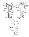
- each contact pad On substrate 20 are pair of conductive electrode contact pads 26a, 26b ( Figures 1-3 , 8 and 12 ) separated from each other and mounted on the wings of the substrate, each contact pad having an electrically conductive lead 28a, 28b mounted on and extending downwardly on the downwardly extending member 24 of the substrate.
- mounted on we mean any kind of mounting but preferably by electrodeposition.
- the leads 28a and 28b are preferably coated with a non-conductive material (e.g., polymeric) to avoid exposure of those leads to the test sample when the electrode subassembly 12 is mounted in the cuvette subassembly with a sample in the cuvette reservoir.
- Each lead (or tracing) 28a, 28b has electrically connected to it a conductive wire 30a, 30b extending below and downwardly away from the downwardly extending member 24.
- Each of the two wires having a horizontal cross-section that is rounded with a cross-sectional dimension from about 0.17 to about 0.38 mm. By “rounded” we mean oval, circular and the like as opposed to square or rectangular with sharp edges.
- the wires are preferably made from palladium (or its alloys), but other metals such as platinum, rhodium, gold, iridium, osmium, rhenium and ruthenium or alloys of the same can also be used.
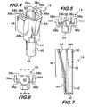
- a rigid or semi-rigid polymeric reinforcing member 34 across the wings ( Figures 1 and 3 ).
- the additional thickness and strength that member 34 provides affords a better fit - preferably an interference fit - into tapered slots 38a, 38b (see e.g. Figures 4, 5 and 7 ) in cuvette subassembly 14 as described below.
- electrode subassembly 12 preferably includes an electrically non-conductive spacer element 36 ( Figures 1-3 , and 8A ) fixed to the lower ends of wires 30a and 30b to assist in holding them in a fixed parallel position to each other.
- Both the substrate 20 and the spacer element 36 are preferably made from polyimide film, preferably Kapton brand.
- the cuvette subassembly 14 of this invention includes a lower reservoir 40 to receive a sample containing platelets.
- the lower reservoir has a substantially flat, closed bottom 42 and a substantially cylindrical wall 44.
- substantially cylindrical we do not mean to exclude some tapering that is illustrated in the drawings.
- Lower reservoir 40 has an internal volume of from about 225 to about 375 ⁇ L, and the reservoir is adapted to receive a sample containing platelets.
- an upper body 46 Extending upwardly from lower reservoir 40 is an upper body 46 ( Figures 4 and 7 ) that includes a pair of arms 48a, 48b.
- Upper body 46 also has a back member 50 that creates a slot 38a, 38b (preferably tapered) between each arm 48a, 48b and back member 50, each slot is adapted to receive a wing 22 from the electrode subassembly (see Figures 4, 5, 7 , and 12 ).
- slots 38a, 38b are tapered, being wider at the top than the bottom 52 ( Figures 7 and 12 ).
- the wings 22a, 22b with reinforcing member 34 behind them create a thickness which in this case is adapted to fit snugly into the bottom 52 of each of the slots 38a, 38b. This preferred fitment holds the electrode subassembly into the cuvette subassembly so that the two hold relatively fixed positions relative to one another when assembled and in use.
- cuvette subassembly 14 are such that when the wings of the electrode subassembly 12 are positioned in slots 38a, 38b, the two wires 30a and 30b are positioned in reservoir 40 and above the inside bottom of reservoir 40 and adapted to be submerged completely in a sample placed in reservoir 40.
- the dimensions of the two subassemblies 12 and 14 are such that there is sufficient space between spacer element 36 and the inside bottom of reservoir to allow a magnetically drivable stir bar 18 to fit easily and without interference on the inside bottom of the reservoir (see, e.g., Figures 8A and 12 ).
- Cuvette subassembly 14 (and specifically upper body 46) further includes a downwardly sloping channel 54 ( Figures 4, 5, 7 and 12 ) sloping downwardly from an upper part of the cuvette subassembly to the approximately the upper part of reservoir 40.
- Channel 54 thus allows reagent(s) to be placed into a sample in reservoir 40 (usually by pipette) without the reagent placement substantially interfering mechanically with electrode 12.
- Cuvette subassembly 14 also includes a pair of rearwardly projecting flanges 56a, 56b that extend rearward from arms 48a, 48b, forming a pair of sidewalls on the cuvette that reduce the chance of hand contact with the electrode subassembly 12 inside the cuvette subassembly 14.
- the lower ends of flanges 56a and 56b rest on the heater/stirrer assembly 16 (see, e.g., Figure 10 ) and assist in positioning the cuvette subassembly in the heater/stirrer assembly.
- flanges 56a and 56b each relative to back member 50 create a pair of openings 58a and 58b (see Figures 4-5 and 10 that allow a pair of electrically conductive contacts (or brushes) 60a, 60b (see Figures 9 , 10 and 14 ) mounted on heater/stirrer assembly 16 to make electrical contact with pads 26a and 26b when assembly 10 is mounted in assembly 16 as shown in Figures 10 and 14 .
- Assembly 10 preferably operates with stir bar 18 ( Figs. 8A and 12 ) adapted to be placed in the bottom of the cuvette reservoir 40, and free to rotate under the influence of an outside source to create a flow of sample in the well and between the two wires 30a and 30b of the electrode subassembly when the electrode subassembly is mounted in the cuvette subassembly, the distances between bottom ends of the two wires and the bottom of the lower reservoir being such that the stir bar can fit in that distance and still create such flow.
- stir bar 18 Figs. 8A and 12
- the heater/stirrer assembly 16 ( Figures 9-12 ) includes a heater block 62 that contains a well 63 ( Figure 12 ) that receives reservoir 40 when cuvette subassembly14 is mounted in assembly 16.
- the heater block has a heating element (not illustrated) that can warm the block and the reservoir to an appropriate temperature (i.e. about 37 °C) for sample analysis.
- Heater/stirrer assembly 16 ( Figure 12 ) also includes a stirrer motor 64 that is operably connected via a motor shaft 66 to turn a magnetic stirrer 68, which proximate enough to the bottom of reservoir 40 such that stirrer 68 can spin stir bar 18 in the bottom of reservoir 40 when stirrer 68 is spun by motor 64.
- stirrer motor 64 operably connected via a motor shaft 66 to turn a magnetic stirrer 68, which proximate enough to the bottom of reservoir 40 such that stirrer 68 can spin stir bar 18 in the bottom of reservoir 40 when stirrer 68 is spun by motor 64.
- the sample in reservoir 40 can be mixed and circulated between wires 30a and 30b.
- heater block 62 has a recess 70 ( Figures 9 and 12 ) that generally conforms to the shape of cuvette subassembly 14 to hold the cuvette subassembly 14 steady when in use and to allow good thermal contact with the cuvette subassembly to allow the sample to be heated.
- This invention allows for the monitoring of platelet aggregation in a small sample size, using a low-cost disposable electrode assembly.
- This electrode assembly consists of an electrode, a plastic cuvette and a stir bar, which fits into a sample chamber.
- the sample chamber is heated at 37° C and the stir bar is typically spun at 1000 RPM but can be spun from 500 to 1200 RPM.
- the electrode has two fine palladium alloy wires evenly spaced with both ends secured to Kapton. A small voltage difference is applied through contacts 60, and ultimately across wires 30a and 30b to measure the impedance of the sample. These wires are set apart about 0.18 to about 0.42 mm apart, which is close enough to allow a platelet aggregation plug to bridge the wires and produce a stable result.
- the new electrode configuration allows the wires to be completely submerged in a smaller sample volume.
- the position of the wires is important to accurate test results.
- the electrode wires should be completely submerged within the sample (i.e. are completely covered by the sample). When completely submerged the location of the wires should be where there is sufficient stirring with an even flow pattern, and where the wire electrodes do not interfere with the stir bar.
- the cuvette subassembly can be a made from plastic so it can produced at a low cost using injection molding.
- the cuvette was designed with the following features so that it fits this use:
- the cuvette is inserted into a sample chamber heated to 37° C.
- the sample chamber consist of two parts, a socket, which has two spring loaded contacts 60 that make electrical contact with the contact pads 26a, 26b, and a heater block, which contains the heating element and temperature sensors.
- a motor 64 and magnet assembly 68 mounted below the heater block is a motor 64 and magnet assembly 68 which when power is applied, spins at 1000 RPM.
- the magnet mounted on the motor provides a magnetic force that spins the stir bar in the cuvette.
- There are cables and connectors mounted to the heater block assembly that connects components embedded in the heater block assembly to a printed circuit board ("PCB"; not shown).
- PCB printed circuit board
- the results can be recorded on a strip chart recorder or to a computer using available software.
Claims (5)
- Ensemble (10) de mesure d'agrégation de plaquettes, comprenant :a. un sous-ensemble d'électrodes (12) comprenant :i. un substrat électriquement non conducteur (20) avec deux ailes (22a, 22b) à son sommet s'étendant horizontalement à l'écart l'une de l'autre dans des sens opposés avec un organe s'étendant vers le bas (24) ;ii. une paire de contacts d'électrodes, chaque contact ayant un fil électriquement conducteur (28a, 28b) s'étendant vers le bas sur l'organe s'étendant vers le bas (24) du substrat (20), chaque fil conducteur (28a, 28b) étant électriquement relié à un fil conducteur (30a, 30b) s'étendant au-dessous et vers le bas à l'écart de l'organe s'étendant vers le bas (24), chacun des deux fils (30a, 30b) ayant une coupe transversale horizontale qui est arrondie avec une dimension de coupe transversale de 0,17 mm à 0,38 mm, où les portions des deux fils (30a, 30b) qui s'étendent vers le bas à l'écart l'une de l'autre sont sensiblement parallèles et ont une longueur de 1,9 mm à 4,5 mm ;b. un sous-ensemble de cuvette (14) comprenant :i. un réservoir inférieur (40) pour recevoir un échantillon contenant des plaquettes, le réservoir inférieur (40) ayant un fond fermé sensiblement plat (42) et ayant une paroi sensiblement cylindrique (44), le réservoir étant adapté pour recevoir un échantillon contenant des plaquettes ;ii. un corps supérieur (46) s'étendant vers le haut à partir du réservoir inférieur (40) et comprenant :a. une paire de bras (48a, 48b) et un organe arrière (50) avec une fente (38a, 38b) formée entre chaque bras (48a, 48b) et l'organe arrière (50), chaque fente (38a, 38b) étant adapté pour recevoir une aile (22) du sous-ensemble d'électrodes (12) ;b. les dimensions du sous-ensemble de cuvette (14) étant telles que, lorsque les ailes (22) du sous-ensemble d'électrodes (12) sont positionnées dans les fentes (38a, 38b), les deux fils (30a, 30b) sont positionnés dans le réservoir (40) et au-dessus du fond (42) du réservoir (40) et sont adaptés pour être immergés dans un échantillon placé dans le réservoir (40) ;c. un canal (54) d'une partie supérieure du sous-ensemble de cuvette (14) à environ la partie supérieure du réservoir (40), adapté pour permettre à un réactif d'être placé dans l'échantillon sensiblement sans interférence mécanique avec l'électrode (12) ;c. un barreau (18) adapté pour être placé dans le fond du puits de cuvette de manière à pouvoir tourner sous l'influence d'une source externe afin de créer un flux d'échantillon dans le puits et entre les deux fils (30a, 30b) du sous-ensemble d'électrodes lorsque le sous-ensemble d'électrodes est monté dans le sous-ensemble de cuvette (12), les distances entre des extrémités inférieures des deux fils (30a, 30b) et le fond du réservoir inférieur étant telles que le barreau puisse entrer dans cette distance et toujours créer un tel flux,
caractérisé en ce que
la paire de contacts d'électrodes est une paire de plots de contacts d'électrodes (26a, 26b) séparés l'un de l'autre et montés sur les ailes (22a, 22b) du substrat (20), les portions des deux fils qui s'étendent vers le bas à l'écart l'un de l'autre sont espacées l'une de l'autre de 0,18 mm à 0,42 mm, et le réservoir inférieur à un volume interne de 225 ml à 375 ml. - Ensemble selon la revendication 1, dans lequel chacun des bras de sous-ensemble de cuvette (48a, 48b) contient une bride (56a, 56b) formant une ouverture entre celle-ci et l'organe arrière (50), où chaque ouverture permet l'établissement d'un contact électrique avec l'un des plots de contact à partir de l'extérieur de l'ensemble.
- Ensemble selon la revendication 2, dans lequel l'ensemble est monté dans un ensemble de bloc de chauffage (62), et les plots de contact (26a, 26b) et des ouvertures sont agencés verticalement.
- Ensemble selon la revendication 1, dans lequel les fils sont positionnés sur le substrat (20) de sorte que, lorsque le sous-ensemble d'électrodes est monté dans le sous-ensemble de cuvette, les fils (30a, 30b) sont décalés par rapport au centre du réservoir (40).
- Ensemble selon la revendication 1, dans lequel les ailes (22a, 22b) du sous-ensemble d'électrodes (12) incluent un organe de renforcement qui recouvre les ailes (22a, 22b), et les fentes (38a, 38b) sur le sous-ensemble de cuvette (14) sont effilées et dimensionnées pour recevoir les ailes (22a, 22b) et l'organe de renforcement avec un frettage pour maintenir le sous-ensemble d'électrodes (12) à une position sensiblement fixe dans le sous-ensemble de cuvette (14) en utilisation.
Applications Claiming Priority (1)
| Application Number | Priority Date | Filing Date | Title |
|---|---|---|---|
| US13/275,402 US8617468B2 (en) | 2011-10-18 | 2011-10-18 | Platelet aggregation test and device |
Publications (2)
| Publication Number | Publication Date |
|---|---|
| EP2584357A1 EP2584357A1 (fr) | 2013-04-24 |
| EP2584357B1 true EP2584357B1 (fr) | 2015-10-14 |
Family
ID=45440024
Family Applications (1)
| Application Number | Title | Priority Date | Filing Date |
|---|---|---|---|
| EP11009743.3A Active EP2584357B1 (fr) | 2011-10-18 | 2011-12-09 | Dispositif pour mesurer l'agrégation des plaquettes |
Country Status (2)
| Country | Link |
|---|---|
| US (4) | US8617468B2 (fr) |
| EP (1) | EP2584357B1 (fr) |
Families Citing this family (9)
| Publication number | Priority date | Publication date | Assignee | Title |
|---|---|---|---|---|
| ES2340378T3 (es) * | 2003-12-16 | 2010-06-02 | Dynabyte Informationssysteme Gmbh | Dispositivo de cartucho para el analisis de sangre. |
| US9579040B2 (en) * | 2011-09-01 | 2017-02-28 | Mc10, Inc. | Electronics for detection of a condition of tissue |
| US8772040B2 (en) * | 2012-08-31 | 2014-07-08 | Korea University Research And Business Foundation | Apparatus and method of platelet multi-function analysis, and micro stirring chip |
| JP6276087B2 (ja) * | 2014-03-28 | 2018-02-07 | シスメックス株式会社 | 検体分析装置及び検体分析方法 |
| US9891209B2 (en) * | 2015-05-29 | 2018-02-13 | C A Casyso Gmbh | Electrode assembly for measurement of platelet function in whole blood |
| US20200055044A1 (en) * | 2016-11-02 | 2020-02-20 | Atantares Corp. | Methods and systems for micro platelet function testing using an integrated miniaturized platelet function analyzer |
| IT201700044103A1 (it) * | 2017-04-21 | 2018-10-21 | Ali Group Srl Carpigiani | Apparecchiatura e metodo per la determinazione di carica batterica in un prodotto liquido o semiliquido. |
| CN114460153A (zh) * | 2022-01-27 | 2022-05-10 | 安邦(厦门)生物科技有限公司 | 一种用于检测全血血小板聚集功能的装置和方法 |
| WO2023176848A1 (fr) * | 2022-03-14 | 2023-09-21 | 日置電機株式会社 | Cellule de mesure et dispositif de connexion |
Family Cites Families (12)
| Publication number | Priority date | Publication date | Assignee | Title |
|---|---|---|---|---|
| US2555937A (en) | 1949-08-25 | 1951-06-05 | Robert L Rosenthal | Method and apparatus for measuring resistance of blood during clotting |
| US4123701A (en) | 1976-07-01 | 1978-10-31 | United States Surgical Corporation | Disposable sample card having a well with electrodes for testing a liquid sample |
| CA1140212A (fr) | 1978-10-02 | 1983-01-25 | Roderick J. Flower | Methode et appareil utilises pour surveiller l'agregation plaquettaire et module d'essai |
| US4301414A (en) | 1979-10-29 | 1981-11-17 | United States Surgical Corporation | Disposable sample card and method of making same |
| US4591793A (en) | 1984-06-14 | 1986-05-27 | Freilich Arthur H | Aggregometer electrode structures |
| JPS62226057A (ja) | 1986-03-28 | 1987-10-05 | Minoru Tomita | 全血用赤血球の凝集率測定方法及びその装置 |
| WO1994006007A1 (fr) | 1992-09-04 | 1994-03-17 | Gradipore Limited | Appareil et procede de detection de la coagulation/lyse de liquides |
| US6004818A (en) * | 1997-08-07 | 1999-12-21 | Chrono-Log Corporation | Aggregometer with disposable test cell |
| EP2187201B1 (fr) | 2003-12-16 | 2012-02-15 | Dynabyte Informationssysteme GmbH | Dispositif de cartouche pour analyse de sang |
| ES2340378T3 (es) * | 2003-12-16 | 2010-06-02 | Dynabyte Informationssysteme Gmbh | Dispositivo de cartucho para el analisis de sangre. |
| ATE484746T1 (de) * | 2008-04-22 | 2010-10-15 | Holger Behnk | Aggregometer |
| EP2500095A1 (fr) * | 2011-03-15 | 2012-09-19 | Siemens Healthcare Diagnostics Products GmbH | Dispositifs et procédé de détermination de la fonction plaquettaire dans un analyseur centrifuge |
-
2011
- 2011-10-18 US US13/275,402 patent/US8617468B2/en active Active
- 2011-12-09 EP EP11009743.3A patent/EP2584357B1/fr active Active
-
2013
- 2013-12-03 US US13/998,758 patent/US9081002B2/en not_active Expired - Fee Related
-
2015
- 2015-06-04 US US14/730,770 patent/US9194875B2/en active Active
- 2015-10-16 US US14/885,567 patent/US20160033475A1/en not_active Abandoned
Also Published As
| Publication number | Publication date |
|---|---|
| US9194875B2 (en) | 2015-11-24 |
| US8617468B2 (en) | 2013-12-31 |
| US20160033475A1 (en) | 2016-02-04 |
| US20140093429A1 (en) | 2014-04-03 |
| US20130094998A1 (en) | 2013-04-18 |
| US9081002B2 (en) | 2015-07-14 |
| US20150276770A1 (en) | 2015-10-01 |
| EP2584357A1 (fr) | 2013-04-24 |
Similar Documents
| Publication | Publication Date | Title |
|---|---|---|
| US9194875B2 (en) | Platelet aggregation test and device | |
| US7901629B2 (en) | Cartridge device for blood analysis | |
| EP1004020B1 (fr) | Agregometre a cellule de test jetable | |
| JP3525837B2 (ja) | 電気生理自動計測装置及び電気生理自動計測方法 | |
| US7021122B1 (en) | Device for the determination of blood clotting by capacitance or resistance | |
| WO2004109277A1 (fr) | Procede et dispositif d'un analyse d'un liquide | |
| WO1999047907A1 (fr) | Dispositif de determination de la coagulation du sang par capacite ou resistance | |
| CN107850559B (zh) | 用于测量全血中血小板功能的电极组件 | |
| EP2187201B1 (fr) | Dispositif de cartouche pour analyse de sang | |
| ES2806352T3 (es) | Sistema de análisis de elemento de prueba | |
| JP2001201481A (ja) | 電気生理自動計測装置及び電気生理自動計測方法 | |
| SU1347013A1 (ru) | Способ определени резистентности эритроцитов | |
| Ehrmantraut et al. | Automatic Prothrombin Instrument |
Legal Events
| Date | Code | Title | Description |
|---|---|---|---|
| PUAI | Public reference made under article 153(3) epc to a published international application that has entered the european phase |
Free format text: ORIGINAL CODE: 0009012 |
|
| AK | Designated contracting states |
Kind code of ref document: A1 Designated state(s): AL AT BE BG CH CY CZ DE DK EE ES FI FR GB GR HR HU IE IS IT LI LT LU LV MC MK MT NL NO PL PT RO RS SE SI SK SM TR |
|
| AX | Request for extension of the european patent |
Extension state: BA ME |
|
| 17P | Request for examination filed |
Effective date: 20131023 |
|
| RAX | Requested extension states of the european patent have changed |
Extension state: ME Payment date: 20131023 Extension state: BA Payment date: 20131023 |
|
| RBV | Designated contracting states (corrected) |
Designated state(s): AL AT BE BG CH CY CZ DE DK EE ES FI FR GB GR HR HU IE IS IT LI LT LU LV MC MK MT NL NO PL PT RO RS SE SI SK SM TR |
|
| REG | Reference to a national code |
Ref country code: DE Ref legal event code: R079 Ref document number: 602011020495 Country of ref document: DE Free format text: PREVIOUS MAIN CLASS: G01N0033490000 Ipc: G01N0033500000 |
|
| GRAP | Despatch of communication of intention to grant a patent |
Free format text: ORIGINAL CODE: EPIDOSNIGR1 |
|
| RIC1 | Information provided on ipc code assigned before grant |
Ipc: G01N 33/50 20060101AFI20150408BHEP Ipc: G01N 27/07 20060101ALI20150408BHEP Ipc: G01N 33/49 20060101ALI20150408BHEP |
|
| INTG | Intention to grant announced |
Effective date: 20150508 |
|
| GRAS | Grant fee paid |
Free format text: ORIGINAL CODE: EPIDOSNIGR3 |
|
| GRAA | (expected) grant |
Free format text: ORIGINAL CODE: 0009210 |
|
| AK | Designated contracting states |
Kind code of ref document: B1 Designated state(s): AL AT BE BG CH CY CZ DE DK EE ES FI FR GB GR HR HU IE IS IT LI LT LU LV MC MK MT NL NO PL PT RO RS SE SI SK SM TR |
|
| AX | Request for extension of the european patent |
Extension state: BA ME |
|
| REG | Reference to a national code |
Ref country code: GB Ref legal event code: FG4D |
|
| REG | Reference to a national code |
Ref country code: AT Ref legal event code: REF Ref document number: 755529 Country of ref document: AT Kind code of ref document: T Effective date: 20151015 Ref country code: CH Ref legal event code: EP |
|
| REG | Reference to a national code |
Ref country code: IE Ref legal event code: FG4D |
|
| REG | Reference to a national code |
Ref country code: DE Ref legal event code: R096 Ref document number: 602011020495 Country of ref document: DE |
|
| REG | Reference to a national code |
Ref country code: FR Ref legal event code: PLFP Year of fee payment: 5 |
|
| REG | Reference to a national code |
Ref country code: NL Ref legal event code: FP |
|
| REG | Reference to a national code |
Ref country code: LT Ref legal event code: MG4D |
|
| REG | Reference to a national code |
Ref country code: AT Ref legal event code: MK05 Ref document number: 755529 Country of ref document: AT Kind code of ref document: T Effective date: 20151014 |
|
| PG25 | Lapsed in a contracting state [announced via postgrant information from national office to epo] |
Ref country code: LT Free format text: LAPSE BECAUSE OF FAILURE TO SUBMIT A TRANSLATION OF THE DESCRIPTION OR TO PAY THE FEE WITHIN THE PRESCRIBED TIME-LIMIT Effective date: 20151014 Ref country code: NO Free format text: LAPSE BECAUSE OF FAILURE TO SUBMIT A TRANSLATION OF THE DESCRIPTION OR TO PAY THE FEE WITHIN THE PRESCRIBED TIME-LIMIT Effective date: 20160114 Ref country code: IS Free format text: LAPSE BECAUSE OF FAILURE TO SUBMIT A TRANSLATION OF THE DESCRIPTION OR TO PAY THE FEE WITHIN THE PRESCRIBED TIME-LIMIT Effective date: 20160214 Ref country code: ES Free format text: LAPSE BECAUSE OF FAILURE TO SUBMIT A TRANSLATION OF THE DESCRIPTION OR TO PAY THE FEE WITHIN THE PRESCRIBED TIME-LIMIT Effective date: 20151014 Ref country code: HR Free format text: LAPSE BECAUSE OF FAILURE TO SUBMIT A TRANSLATION OF THE DESCRIPTION OR TO PAY THE FEE WITHIN THE PRESCRIBED TIME-LIMIT Effective date: 20151014 |
|
| PG25 | Lapsed in a contracting state [announced via postgrant information from national office to epo] |
Ref country code: BE Free format text: LAPSE BECAUSE OF NON-PAYMENT OF DUE FEES Effective date: 20151231 Ref country code: RS Free format text: LAPSE BECAUSE OF FAILURE TO SUBMIT A TRANSLATION OF THE DESCRIPTION OR TO PAY THE FEE WITHIN THE PRESCRIBED TIME-LIMIT Effective date: 20151014 Ref country code: LV Free format text: LAPSE BECAUSE OF FAILURE TO SUBMIT A TRANSLATION OF THE DESCRIPTION OR TO PAY THE FEE WITHIN THE PRESCRIBED TIME-LIMIT Effective date: 20151014 Ref country code: GR Free format text: LAPSE BECAUSE OF FAILURE TO SUBMIT A TRANSLATION OF THE DESCRIPTION OR TO PAY THE FEE WITHIN THE PRESCRIBED TIME-LIMIT Effective date: 20160115 Ref country code: SE Free format text: LAPSE BECAUSE OF FAILURE TO SUBMIT A TRANSLATION OF THE DESCRIPTION OR TO PAY THE FEE WITHIN THE PRESCRIBED TIME-LIMIT Effective date: 20151014 Ref country code: PT Free format text: LAPSE BECAUSE OF FAILURE TO SUBMIT A TRANSLATION OF THE DESCRIPTION OR TO PAY THE FEE WITHIN THE PRESCRIBED TIME-LIMIT Effective date: 20160215 Ref country code: FI Free format text: LAPSE BECAUSE OF FAILURE TO SUBMIT A TRANSLATION OF THE DESCRIPTION OR TO PAY THE FEE WITHIN THE PRESCRIBED TIME-LIMIT Effective date: 20151014 Ref country code: AT Free format text: LAPSE BECAUSE OF FAILURE TO SUBMIT A TRANSLATION OF THE DESCRIPTION OR TO PAY THE FEE WITHIN THE PRESCRIBED TIME-LIMIT Effective date: 20151014 Ref country code: PL Free format text: LAPSE BECAUSE OF FAILURE TO SUBMIT A TRANSLATION OF THE DESCRIPTION OR TO PAY THE FEE WITHIN THE PRESCRIBED TIME-LIMIT Effective date: 20151014 |
|
| REG | Reference to a national code |
Ref country code: DE Ref legal event code: R097 Ref document number: 602011020495 Country of ref document: DE |
|
| PG25 | Lapsed in a contracting state [announced via postgrant information from national office to epo] |
Ref country code: LU Free format text: LAPSE BECAUSE OF FAILURE TO SUBMIT A TRANSLATION OF THE DESCRIPTION OR TO PAY THE FEE WITHIN THE PRESCRIBED TIME-LIMIT Effective date: 20151209 Ref country code: MC Free format text: LAPSE BECAUSE OF FAILURE TO SUBMIT A TRANSLATION OF THE DESCRIPTION OR TO PAY THE FEE WITHIN THE PRESCRIBED TIME-LIMIT Effective date: 20151014 Ref country code: CZ Free format text: LAPSE BECAUSE OF FAILURE TO SUBMIT A TRANSLATION OF THE DESCRIPTION OR TO PAY THE FEE WITHIN THE PRESCRIBED TIME-LIMIT Effective date: 20151014 |
|
| REG | Reference to a national code |
Ref country code: CH Ref legal event code: PL |
|
| PLBE | No opposition filed within time limit |
Free format text: ORIGINAL CODE: 0009261 |
|
| STAA | Information on the status of an ep patent application or granted ep patent |
Free format text: STATUS: NO OPPOSITION FILED WITHIN TIME LIMIT |
|
| PG25 | Lapsed in a contracting state [announced via postgrant information from national office to epo] |
Ref country code: RO Free format text: LAPSE BECAUSE OF FAILURE TO SUBMIT A TRANSLATION OF THE DESCRIPTION OR TO PAY THE FEE WITHIN THE PRESCRIBED TIME-LIMIT Effective date: 20151014 Ref country code: SK Free format text: LAPSE BECAUSE OF FAILURE TO SUBMIT A TRANSLATION OF THE DESCRIPTION OR TO PAY THE FEE WITHIN THE PRESCRIBED TIME-LIMIT Effective date: 20151014 Ref country code: SM Free format text: LAPSE BECAUSE OF FAILURE TO SUBMIT A TRANSLATION OF THE DESCRIPTION OR TO PAY THE FEE WITHIN THE PRESCRIBED TIME-LIMIT Effective date: 20151014 Ref country code: EE Free format text: LAPSE BECAUSE OF FAILURE TO SUBMIT A TRANSLATION OF THE DESCRIPTION OR TO PAY THE FEE WITHIN THE PRESCRIBED TIME-LIMIT Effective date: 20151014 Ref country code: DK Free format text: LAPSE BECAUSE OF FAILURE TO SUBMIT A TRANSLATION OF THE DESCRIPTION OR TO PAY THE FEE WITHIN THE PRESCRIBED TIME-LIMIT Effective date: 20151014 |
|
| 26N | No opposition filed |
Effective date: 20160715 |
|
| REG | Reference to a national code |
Ref country code: IE Ref legal event code: MM4A |
|
| PG25 | Lapsed in a contracting state [announced via postgrant information from national office to epo] |
Ref country code: CH Free format text: LAPSE BECAUSE OF NON-PAYMENT OF DUE FEES Effective date: 20151231 Ref country code: IE Free format text: LAPSE BECAUSE OF NON-PAYMENT OF DUE FEES Effective date: 20151209 Ref country code: LI Free format text: LAPSE BECAUSE OF NON-PAYMENT OF DUE FEES Effective date: 20151231 |
|
| REG | Reference to a national code |
Ref country code: FR Ref legal event code: PLFP Year of fee payment: 6 |
|
| PG25 | Lapsed in a contracting state [announced via postgrant information from national office to epo] |
Ref country code: SI Free format text: LAPSE BECAUSE OF FAILURE TO SUBMIT A TRANSLATION OF THE DESCRIPTION OR TO PAY THE FEE WITHIN THE PRESCRIBED TIME-LIMIT Effective date: 20151014 |
|
| PG25 | Lapsed in a contracting state [announced via postgrant information from national office to epo] |
Ref country code: BE Free format text: LAPSE BECAUSE OF FAILURE TO SUBMIT A TRANSLATION OF THE DESCRIPTION OR TO PAY THE FEE WITHIN THE PRESCRIBED TIME-LIMIT Effective date: 20151014 |
|
| PG25 | Lapsed in a contracting state [announced via postgrant information from national office to epo] |
Ref country code: HU Free format text: LAPSE BECAUSE OF FAILURE TO SUBMIT A TRANSLATION OF THE DESCRIPTION OR TO PAY THE FEE WITHIN THE PRESCRIBED TIME-LIMIT; INVALID AB INITIO Effective date: 20111209 Ref country code: BG Free format text: LAPSE BECAUSE OF FAILURE TO SUBMIT A TRANSLATION OF THE DESCRIPTION OR TO PAY THE FEE WITHIN THE PRESCRIBED TIME-LIMIT Effective date: 20151014 |
|
| PG25 | Lapsed in a contracting state [announced via postgrant information from national office to epo] |
Ref country code: CY Free format text: LAPSE BECAUSE OF FAILURE TO SUBMIT A TRANSLATION OF THE DESCRIPTION OR TO PAY THE FEE WITHIN THE PRESCRIBED TIME-LIMIT Effective date: 20151014 |
|
| PG25 | Lapsed in a contracting state [announced via postgrant information from national office to epo] |
Ref country code: MT Free format text: LAPSE BECAUSE OF FAILURE TO SUBMIT A TRANSLATION OF THE DESCRIPTION OR TO PAY THE FEE WITHIN THE PRESCRIBED TIME-LIMIT Effective date: 20151014 |
|
| REG | Reference to a national code |
Ref country code: FR Ref legal event code: PLFP Year of fee payment: 7 |
|
| PG25 | Lapsed in a contracting state [announced via postgrant information from national office to epo] |
Ref country code: MK Free format text: LAPSE BECAUSE OF FAILURE TO SUBMIT A TRANSLATION OF THE DESCRIPTION OR TO PAY THE FEE WITHIN THE PRESCRIBED TIME-LIMIT Effective date: 20151014 Ref country code: TR Free format text: LAPSE BECAUSE OF FAILURE TO SUBMIT A TRANSLATION OF THE DESCRIPTION OR TO PAY THE FEE WITHIN THE PRESCRIBED TIME-LIMIT Effective date: 20151014 |
|
| PG25 | Lapsed in a contracting state [announced via postgrant information from national office to epo] |
Ref country code: AL Free format text: LAPSE BECAUSE OF FAILURE TO SUBMIT A TRANSLATION OF THE DESCRIPTION OR TO PAY THE FEE WITHIN THE PRESCRIBED TIME-LIMIT Effective date: 20151014 |
|
| PGFP | Annual fee paid to national office [announced via postgrant information from national office to epo] |
Ref country code: GB Payment date: 20211222 Year of fee payment: 11 Ref country code: FR Payment date: 20211220 Year of fee payment: 11 |
|
| PGFP | Annual fee paid to national office [announced via postgrant information from national office to epo] |
Ref country code: NL Payment date: 20211217 Year of fee payment: 11 |
|
| PGFP | Annual fee paid to national office [announced via postgrant information from national office to epo] |
Ref country code: DE Payment date: 20220202 Year of fee payment: 11 |
|
| PGFP | Annual fee paid to national office [announced via postgrant information from national office to epo] |
Ref country code: IT Payment date: 20211230 Year of fee payment: 11 |
|
| REG | Reference to a national code |
Ref country code: DE Ref legal event code: R119 Ref document number: 602011020495 Country of ref document: DE |
|
| REG | Reference to a national code |
Ref country code: NL Ref legal event code: MM Effective date: 20230101 |
|
| GBPC | Gb: european patent ceased through non-payment of renewal fee |
Effective date: 20221209 |
|
| PG25 | Lapsed in a contracting state [announced via postgrant information from national office to epo] |
Ref country code: NL Free format text: LAPSE BECAUSE OF NON-PAYMENT OF DUE FEES Effective date: 20230101 |
|
| PG25 | Lapsed in a contracting state [announced via postgrant information from national office to epo] |
Ref country code: GB Free format text: LAPSE BECAUSE OF NON-PAYMENT OF DUE FEES Effective date: 20221209 Ref country code: DE Free format text: LAPSE BECAUSE OF NON-PAYMENT OF DUE FEES Effective date: 20230701 |
|
| PG25 | Lapsed in a contracting state [announced via postgrant information from national office to epo] |
Ref country code: FR Free format text: LAPSE BECAUSE OF NON-PAYMENT OF DUE FEES Effective date: 20221231 |
|
| PG25 | Lapsed in a contracting state [announced via postgrant information from national office to epo] |
Ref country code: IT Free format text: LAPSE BECAUSE OF NON-PAYMENT OF DUE FEES Effective date: 20221209 |